CN112312948B - Buffers for injection devices - Google Patents
Buffers for injection devicesDownload PDFInfo
- Publication number
- CN112312948B CN112312948BCN201980039376.4ACN201980039376ACN112312948BCN 112312948 BCN112312948 BCN 112312948BCN 201980039376 ACN201980039376 ACN 201980039376ACN 112312948 BCN112312948 BCN 112312948B
- Authority
- CN
- China
- Prior art keywords
- plunger rod
- tip
- injection device
- plunger
- retractable tip
- Prior art date
- Legal status (The legal status is an assumption and is not a legal conclusion. Google has not performed a legal analysis and makes no representation as to the accuracy of the status listed.)
- Active
Links
- 238000002347injectionMethods0.000titleclaimsabstractdescription52
- 239000007924injectionSubstances0.000titleclaimsabstractdescription52
- 239000000872bufferSubstances0.000titleclaimsabstractdescription10
- 239000003814drugSubstances0.000claimsabstractdescription61
- 238000006073displacement reactionMethods0.000claimsabstractdescription4
- 239000006260foamSubstances0.000claimsdescription16
- 230000007246mechanismEffects0.000claimsdescription9
- 238000007789sealingMethods0.000claimsdescription9
- 230000035939shockEffects0.000claimsdescription8
- 101000976075Homo sapiens InsulinProteins0.000description26
- PBGKTOXHQIOBKM-FHFVDXKLSA-Ninsulin (human)Chemical compoundC([C@@H](C(=O)N[C@@H](CC(C)C)C(=O)N[C@H]1CSSC[C@H]2C(=O)N[C@H](C(=O)N[C@@H](CO)C(=O)N[C@H](C(=O)N[C@H](C(N[C@@H](CO)C(=O)N[C@@H](CC(C)C)C(=O)N[C@@H](CC=3C=CC(O)=CC=3)C(=O)N[C@@H](CCC(N)=O)C(=O)N[C@@H](CC(C)C)C(=O)N[C@@H](CCC(O)=O)C(=O)N[C@@H](CC(N)=O)C(=O)N[C@@H](CC=3C=CC(O)=CC=3)C(=O)N[C@@H](CSSC[C@H](NC(=O)[C@H](C(C)C)NC(=O)[C@H](CC(C)C)NC(=O)[C@H](CC=3C=CC(O)=CC=3)NC(=O)[C@H](CC(C)C)NC(=O)[C@H](C)NC(=O)[C@H](CCC(O)=O)NC(=O)[C@H](C(C)C)NC(=O)[C@H](CC(C)C)NC(=O)[C@H](CC=3NC=NC=3)NC(=O)[C@H](CO)NC(=O)CNC1=O)C(=O)NCC(=O)N[C@@H](CCC(O)=O)C(=O)N[C@@H](CCCNC(N)=N)C(=O)NCC(=O)N[C@@H](CC=1C=CC=CC=1)C(=O)N[C@@H](CC=1C=CC=CC=1)C(=O)N[C@@H](CC=1C=CC(O)=CC=1)C(=O)N[C@@H]([C@@H](C)O)C(=O)N1[C@@H](CCC1)C(=O)N[C@@H](CCCCN)C(=O)N[C@@H]([C@@H](C)O)C(O)=O)C(=O)N[C@@H](CC(N)=O)C(O)=O)=O)CSSC[C@@H](C(N2)=O)NC(=O)[C@H](CCC(N)=O)NC(=O)[C@H](CCC(O)=O)NC(=O)[C@H](C(C)C)NC(=O)[C@@H](NC(=O)CN)[C@@H](C)CC)[C@@H](C)CC)[C@@H](C)O)NC(=O)[C@H](CCC(N)=O)NC(=O)[C@H](CC(N)=O)NC(=O)[C@@H](NC(=O)[C@@H](N)CC=1C=CC=CC=1)C(C)C)C1=CN=CN1PBGKTOXHQIOBKM-FHFVDXKLSA-N0.000description25
- 108090000765processed proteins & peptidesProteins0.000description21
- 229940079593drugDrugs0.000description16
- 102000004196processed proteins & peptidesHuman genes0.000description15
- 229920001184polypeptidePolymers0.000description12
- 239000000427antigenSubstances0.000description11
- 102000036639antigensHuman genes0.000description11
- 108091007433antigensProteins0.000description11
- 239000008186active pharmaceutical agentSubstances0.000description10
- 150000001413amino acidsChemical class0.000description9
- 108010021625Immunoglobulin FragmentsProteins0.000description8
- 102000008394Immunoglobulin FragmentsHuman genes0.000description8
- 230000000994depressogenic effectEffects0.000description7
- 150000003839saltsChemical class0.000description7
- 229940090047auto-injectorDrugs0.000description6
- 238000013016dampingMethods0.000description6
- 125000000539amino acid groupChemical group0.000description5
- 208000037265diseases, disorders, signs and symptomsDiseases0.000description5
- 239000012634fragmentSubstances0.000description5
- NOESYZHRGYRDHS-UHFFFAOYSA-NinsulinChemical compoundN1C(=O)C(NC(=O)C(CCC(N)=O)NC(=O)C(CCC(O)=O)NC(=O)C(C(C)C)NC(=O)C(NC(=O)CN)C(C)CC)CSSCC(C(NC(CO)C(=O)NC(CC(C)C)C(=O)NC(CC=2C=CC(O)=CC=2)C(=O)NC(CCC(N)=O)C(=O)NC(CC(C)C)C(=O)NC(CCC(O)=O)C(=O)NC(CC(N)=O)C(=O)NC(CC=2C=CC(O)=CC=2)C(=O)NC(CSSCC(NC(=O)C(C(C)C)NC(=O)C(CC(C)C)NC(=O)C(CC=2C=CC(O)=CC=2)NC(=O)C(CC(C)C)NC(=O)C(C)NC(=O)C(CCC(O)=O)NC(=O)C(C(C)C)NC(=O)C(CC(C)C)NC(=O)C(CC=2NC=NC=2)NC(=O)C(CO)NC(=O)CNC2=O)C(=O)NCC(=O)NC(CCC(O)=O)C(=O)NC(CCCNC(N)=N)C(=O)NCC(=O)NC(CC=3C=CC=CC=3)C(=O)NC(CC=3C=CC=CC=3)C(=O)NC(CC=3C=CC(O)=CC=3)C(=O)NC(C(C)O)C(=O)N3C(CCC3)C(=O)NC(CCCCN)C(=O)NC(C)C(O)=O)C(=O)NC(CC(N)=O)C(O)=O)=O)NC(=O)C(C(C)CC)NC(=O)C(CO)NC(=O)C(C(C)O)NC(=O)C1CSSCC2NC(=O)C(CC(C)C)NC(=O)C(NC(=O)C(CCC(N)=O)NC(=O)C(CC(N)=O)NC(=O)C(NC(=O)C(N)CC=1C=CC=CC=1)C(C)C)CC1=CN=CN1NOESYZHRGYRDHS-UHFFFAOYSA-N0.000description5
- 239000000463materialSubstances0.000description5
- 102100035360Cerebellar degeneration-related antigen 1Human genes0.000description4
- 108060003951ImmunoglobulinProteins0.000description4
- 150000004676glycansChemical class0.000description4
- 102000018358immunoglobulinHuman genes0.000description4
- 230000014759maintenance of locationEffects0.000description4
- 239000000203mixtureSubstances0.000description4
- 229920001282polysaccharidePolymers0.000description4
- 239000005017polysaccharideSubstances0.000description4
- 102000009109Fc receptorsHuman genes0.000description3
- 108010087819Fc receptorsProteins0.000description3
- 241001465754MetazoaSpecies0.000description3
- 238000007792additionMethods0.000description3
- 239000003795chemical substances by applicationSubstances0.000description3
- 208000035475disorderDiseases0.000description3
- 238000012377drug deliveryMethods0.000description3
- 230000009977dual effectEffects0.000description3
- 229940088597hormoneDrugs0.000description3
- 239000005556hormoneSubstances0.000description3
- 230000033001locomotionEffects0.000description3
- 239000003055low molecular weight heparinSubstances0.000description3
- 229940127215low-molecular weight heparinDrugs0.000description3
- KIUKXJAPPMFGSW-DNGZLQJQSA-N(2S,3S,4S,5R,6R)-6-[(2S,3R,4R,5S,6R)-3-Acetamido-2-[(2S,3S,4R,5R,6R)-6-[(2R,3R,4R,5S,6R)-3-acetamido-2,5-dihydroxy-6-(hydroxymethyl)oxan-4-yl]oxy-2-carboxy-4,5-dihydroxyoxan-3-yl]oxy-5-hydroxy-6-(hydroxymethyl)oxan-4-yl]oxy-3,4,5-trihydroxyoxane-2-carboxylic acidChemical compoundCC(=O)N[C@H]1[C@H](O)O[C@H](CO)[C@@H](O)[C@@H]1O[C@H]1[C@H](O)[C@@H](O)[C@H](O[C@H]2[C@@H]([C@@H](O[C@H]3[C@@H]([C@@H](O)[C@H](O)[C@H](O3)C(O)=O)O)[C@H](O)[C@@H](CO)O2)NC(C)=O)[C@@H](C(O)=O)O1KIUKXJAPPMFGSW-DNGZLQJQSA-N0.000description2
- 208000004476Acute Coronary SyndromeDiseases0.000description2
- HTQBXNHDCUEHJF-XWLPCZSASA-NExenatideChemical compoundC([C@@H](C(=O)N[C@@H]([C@@H](C)CC)C(=O)N[C@@H](CCC(O)=O)C(=O)N[C@@H](CC=1C2=CC=CC=C2NC=1)C(=O)N[C@@H](CC(C)C)C(=O)N[C@@H](CCCCN)C(=O)N[C@@H](CC(N)=O)C(=O)NCC(=O)NCC(=O)N1[C@@H](CCC1)C(=O)N[C@@H](CO)C(=O)N[C@@H](CO)C(=O)NCC(=O)N[C@@H](C)C(=O)N1[C@@H](CCC1)C(=O)N1[C@@H](CCC1)C(=O)N1[C@@H](CCC1)C(=O)N[C@@H](CO)C(N)=O)NC(=O)[C@H](CC(C)C)NC(=O)[C@H](CCCNC(N)=N)NC(=O)[C@@H](NC(=O)[C@H](C)NC(=O)[C@H](CCC(O)=O)NC(=O)[C@H](CCC(O)=O)NC(=O)[C@H](CCC(O)=O)NC(=O)[C@H](CCSC)NC(=O)[C@H](CCC(N)=O)NC(=O)[C@H](CCCCN)NC(=O)[C@H](CO)NC(=O)[C@H](CC(C)C)NC(=O)[C@H](CC(O)=O)NC(=O)[C@H](CO)NC(=O)[C@@H](NC(=O)[C@H](CC=1C=CC=CC=1)NC(=O)[C@@H](NC(=O)CNC(=O)[C@H](CCC(O)=O)NC(=O)CNC(=O)[C@@H](N)CC=1NC=NC=1)[C@@H](C)O)[C@@H](C)O)C(C)C)C1=CC=CC=C1HTQBXNHDCUEHJF-XWLPCZSASA-N0.000description2
- 108010011459ExenatideProteins0.000description2
- 229940089838Glucagon-like peptide 1 receptor agonistDrugs0.000description2
- YSDQQAXHVYUZIW-QCIJIYAXSA-NLiraglutideChemical compoundC([C@@H](C(=O)N[C@@H](CC(C)C)C(=O)N[C@@H](CCC(O)=O)C(=O)NCC(=O)N[C@@H](CCC(N)=O)C(=O)N[C@@H](C)C(=O)N[C@@H](C)C(=O)N[C@@H](CCCCNC(=O)CC[C@H](NC(=O)CCCCCCCCCCCCCCC)C(O)=O)C(=O)N[C@@H](CCC(O)=O)C(=O)N[C@@H](CC=1C=CC=CC=1)C(=O)N[C@@H]([C@@H](C)CC)C(=O)N[C@@H](C)C(=O)N[C@@H](CC=1C2=CC=CC=C2NC=1)C(=O)N[C@@H](CC(C)C)C(=O)N[C@@H](C(C)C)C(=O)N[C@@H](CCCNC(N)=N)C(=O)NCC(=O)N[C@@H](CCCNC(N)=N)C(=O)NCC(O)=O)NC(=O)[C@H](CO)NC(=O)[C@H](CO)NC(=O)[C@@H](NC(=O)[C@H](CC(O)=O)NC(=O)[C@H](CO)NC(=O)[C@@H](NC(=O)[C@H](CC=1C=CC=CC=1)NC(=O)[C@@H](NC(=O)CNC(=O)[C@H](CCC(O)=O)NC(=O)[C@H](C)NC(=O)[C@@H](N)CC=1NC=NC=1)[C@@H](C)O)[C@@H](C)O)C(C)C)C1=CC=C(O)C=C1YSDQQAXHVYUZIW-QCIJIYAXSA-N0.000description2
- 108091034117OligonucleotideProteins0.000description2
- 108020004459Small interfering RNAProteins0.000description2
- 206010067584Type 1 diabetes mellitusDiseases0.000description2
- JLCPHMBAVCMARE-UHFFFAOYSA-N[3-[[3-[[3-[[3-[[3-[[3-[[3-[[3-[[3-[[3-[[3-[[5-(2-amino-6-oxo-1H-purin-9-yl)-3-[[3-[[3-[[3-[[3-[[3-[[5-(2-amino-6-oxo-1H-purin-9-yl)-3-[[5-(2-amino-6-oxo-1H-purin-9-yl)-3-hydroxyoxolan-2-yl]methoxy-hydroxyphosphoryl]oxyoxolan-2-yl]methoxy-hydroxyphosphoryl]oxy-5-(5-methyl-2,4-dioxopyrimidin-1-yl)oxolan-2-yl]methoxy-hydroxyphosphoryl]oxy-5-(6-aminopurin-9-yl)oxolan-2-yl]methoxy-hydroxyphosphoryl]oxy-5-(6-aminopurin-9-yl)oxolan-2-yl]methoxy-hydroxyphosphoryl]oxy-5-(6-aminopurin-9-yl)oxolan-2-yl]methoxy-hydroxyphosphoryl]oxy-5-(6-aminopurin-9-yl)oxolan-2-yl]methoxy-hydroxyphosphoryl]oxyoxolan-2-yl]methoxy-hydroxyphosphoryl]oxy-5-(5-methyl-2,4-dioxopyrimidin-1-yl)oxolan-2-yl]methoxy-hydroxyphosphoryl]oxy-5-(4-amino-2-oxopyrimidin-1-yl)oxolan-2-yl]methoxy-hydroxyphosphoryl]oxy-5-(5-methyl-2,4-dioxopyrimidin-1-yl)oxolan-2-yl]methoxy-hydroxyphosphoryl]oxy-5-(5-methyl-2,4-dioxopyrimidin-1-yl)oxolan-2-yl]methoxy-hydroxyphosphoryl]oxy-5-(6-aminopurin-9-yl)oxolan-2-yl]methoxy-hydroxyphosphoryl]oxy-5-(6-aminopurin-9-yl)oxolan-2-yl]methoxy-hydroxyphosphoryl]oxy-5-(4-amino-2-oxopyrimidin-1-yl)oxolan-2-yl]methoxy-hydroxyphosphoryl]oxy-5-(4-amino-2-oxopyrimidin-1-yl)oxolan-2-yl]methoxy-hydroxyphosphoryl]oxy-5-(4-amino-2-oxopyrimidin-1-yl)oxolan-2-yl]methoxy-hydroxyphosphoryl]oxy-5-(6-aminopurin-9-yl)oxolan-2-yl]methoxy-hydroxyphosphoryl]oxy-5-(4-amino-2-oxopyrimidin-1-yl)oxolan-2-yl]methyl [5-(6-aminopurin-9-yl)-2-(hydroxymethyl)oxolan-3-yl] hydrogen phosphatePolymersCc1cn(C2CC(OP(O)(=O)OCC3OC(CC3OP(O)(=O)OCC3OC(CC3O)n3cnc4c3nc(N)[nH]c4=O)n3cnc4c3nc(N)[nH]c4=O)C(COP(O)(=O)OC3CC(OC3COP(O)(=O)OC3CC(OC3COP(O)(=O)OC3CC(OC3COP(O)(=O)OC3CC(OC3COP(O)(=O)OC3CC(OC3COP(O)(=O)OC3CC(OC3COP(O)(=O)OC3CC(OC3COP(O)(=O)OC3CC(OC3COP(O)(=O)OC3CC(OC3COP(O)(=O)OC3CC(OC3COP(O)(=O)OC3CC(OC3COP(O)(=O)OC3CC(OC3COP(O)(=O)OC3CC(OC3COP(O)(=O)OC3CC(OC3COP(O)(=O)OC3CC(OC3COP(O)(=O)OC3CC(OC3COP(O)(=O)OC3CC(OC3CO)n3cnc4c(N)ncnc34)n3ccc(N)nc3=O)n3cnc4c(N)ncnc34)n3ccc(N)nc3=O)n3ccc(N)nc3=O)n3ccc(N)nc3=O)n3cnc4c(N)ncnc34)n3cnc4c(N)ncnc34)n3cc(C)c(=O)[nH]c3=O)n3cc(C)c(=O)[nH]c3=O)n3ccc(N)nc3=O)n3cc(C)c(=O)[nH]c3=O)n3cnc4c3nc(N)[nH]c4=O)n3cnc4c(N)ncnc34)n3cnc4c(N)ncnc34)n3cnc4c(N)ncnc34)n3cnc4c(N)ncnc34)O2)c(=O)[nH]c1=OJLCPHMBAVCMARE-UHFFFAOYSA-N0.000description2
- 238000010521absorption reactionMethods0.000description2
- 230000000692anti-sense effectEffects0.000description2
- -1antibodiesProteins0.000description2
- 230000003247decreasing effectEffects0.000description2
- 206010012601diabetes mellitusDiseases0.000description2
- 229940090124dipeptidyl peptidase 4 (dpp-4) inhibitors for blood glucose loweringDrugs0.000description2
- 201000010099diseaseDiseases0.000description2
- 229950003468dupilumabDrugs0.000description2
- 230000000694effectsEffects0.000description2
- 229960001519exenatideDrugs0.000description2
- 238000009472formulationMethods0.000description2
- 238000000034methodMethods0.000description2
- 238000012986modificationMethods0.000description2
- 230000004048modificationEffects0.000description2
- 108020004707nucleic acidsProteins0.000description2
- 102000039446nucleic acidsHuman genes0.000description2
- 150000007523nucleic acidsChemical class0.000description2
- 239000008194pharmaceutical compositionSubstances0.000description2
- 108090000623proteins and genesProteins0.000description2
- 239000004055small Interfering RNASubstances0.000description2
- 239000012453solvateSubstances0.000description2
- 208000001072type 2 diabetes mellitusDiseases0.000description2
- MSFZPBXAGPYVFD-NFBCFJMWSA-N(2r)-2-amino-3-[1-[3-[2-[2-[2-[4-[[(5s)-5,6-diamino-6-oxohexyl]amino]butylamino]-2-oxoethoxy]ethoxy]ethylamino]-3-oxopropyl]-2,5-dioxopyrrolidin-3-yl]sulfanylpropanoic acidChemical compoundNC(=O)[C@@H](N)CCCCNCCCCNC(=O)COCCOCCNC(=O)CCN1C(=O)CC(SC[C@H](N)C(O)=O)C1=OMSFZPBXAGPYVFD-NFBCFJMWSA-N0.000description1
- 108091032973(ribonucleotides)n+mProteins0.000description1
- 208000035285Allergic Seasonal RhinitisDiseases0.000description1
- 206010002383Angina PectorisDiseases0.000description1
- 108020004491Antisense DNAProteins0.000description1
- 108020005544Antisense RNAProteins0.000description1
- 201000001320AtherosclerosisDiseases0.000description1
- 108010037003BuserelinProteins0.000description1
- 108090000994Catalytic RNAProteins0.000description1
- 102000053642Catalytic RNAHuman genes0.000description1
- 102000011022Chorionic GonadotropinHuman genes0.000description1
- 108010062540Chorionic GonadotropinProteins0.000description1
- 208000017667Chronic DiseaseDiseases0.000description1
- 108010047041Complementarity Determining RegionsProteins0.000description1
- 108020004414DNAProteins0.000description1
- 108010000437Deamino Arginine VasopressinProteins0.000description1
- URRAHSMDPCMOTH-LNLFQRSKSA-NDenagliptinChemical compoundC=1C=C(F)C=CC=1C([C@H](N)C(=O)N1[C@@H](C[C@H](F)C1)C#N)C1=CC=C(F)C=C1URRAHSMDPCMOTH-LNLFQRSKSA-N0.000description1
- 206010012689Diabetic retinopathyDiseases0.000description1
- 102000004190EnzymesHuman genes0.000description1
- 108090000790EnzymesProteins0.000description1
- 102000012673Follicle Stimulating HormoneHuman genes0.000description1
- 108010079345Follicle Stimulating HormoneProteins0.000description1
- 102000051325GlucagonHuman genes0.000description1
- 108060003199GlucagonProteins0.000description1
- 102400000932Gonadoliberin-1Human genes0.000description1
- 102000006771GonadotropinsHuman genes0.000description1
- 108010086677GonadotropinsProteins0.000description1
- 108010069236GoserelinProteins0.000description1
- BLCLNMBMMGCOAS-URPVMXJPSA-NGoserelinChemical compoundC([C@@H](C(=O)N[C@H](COC(C)(C)C)C(=O)N[C@@H](CC(C)C)C(=O)N[C@@H](CCCN=C(N)N)C(=O)N1[C@@H](CCC1)C(=O)NNC(N)=O)NC(=O)[C@H](CO)NC(=O)[C@H](CC=1C2=CC=CC=C2NC=1)NC(=O)[C@H](CC=1NC=NC=1)NC(=O)[C@H]1NC(=O)CC1)C1=CC=C(O)C=C1BLCLNMBMMGCOAS-URPVMXJPSA-N0.000description1
- 241000270431Heloderma suspectumSpecies0.000description1
- HTTJABKRGRZYRN-UHFFFAOYSA-NHeparinChemical compoundOC1C(NC(=O)C)C(O)OC(COS(O)(=O)=O)C1OC1C(OS(O)(=O)=O)C(O)C(OC2C(C(OS(O)(=O)=O)C(OC3C(C(O)C(O)C(O3)C(O)=O)OS(O)(=O)=O)C(CO)O2)NS(O)(=O)=O)C(C(O)=O)O1HTTJABKRGRZYRN-UHFFFAOYSA-N0.000description1
- 241000282412HomoSpecies0.000description1
- 101500026183Homo sapiens Gonadoliberin-1Proteins0.000description1
- 101000825742Homo sapiens SomatoliberinProteins0.000description1
- 208000000563Hyperlipoproteinemia Type IIDiseases0.000description1
- 108010024118Hypothalamic HormonesProteins0.000description1
- 102000015611Hypothalamic HormonesHuman genes0.000description1
- DGAQECJNVWCQMB-PUAWFVPOSA-MIlexoside XXIXChemical compoundC[C@@H]1CC[C@@]2(CC[C@@]3(C(=CC[C@H]4[C@]3(CC[C@@H]5[C@@]4(CC[C@@H](C5(C)C)OS(=O)(=O)[O-])C)C)[C@@H]2[C@]1(C)O)C)C(=O)O[C@H]6[C@@H]([C@H]([C@@H]([C@H](O6)CO)O)O)O.[Na+]DGAQECJNVWCQMB-PUAWFVPOSA-M0.000description1
- 108010054477Immunoglobulin Fab FragmentsProteins0.000description1
- 102000001706Immunoglobulin Fab FragmentsHuman genes0.000description1
- 206010061218InflammationDiseases0.000description1
- 108090001061InsulinProteins0.000description1
- 102000004877InsulinHuman genes0.000description1
- 108010073961Insulin AspartProteins0.000description1
- 108010089308Insulin DetemirProteins0.000description1
- 108010057186Insulin GlargineProteins0.000description1
- 108010065920Insulin LisproProteins0.000description1
- 102000003746Insulin ReceptorHuman genes0.000description1
- 108010001127Insulin ReceptorProteins0.000description1
- FYZPCMFQCNBYCY-WIWKJPBBSA-NInsulin degludecChemical compoundCC[C@H](C)[C@H](NC(=O)CN)C(=O)N[C@@H](C(C)C)C(=O)N[C@@H](CCC(O)=O)C(=O)N[C@@H](CCC(N)=O)C(=O)N[C@H]1CSSC[C@@H]2NC(=O)[C@@H](NC(=O)[C@H](CO)NC(=O)[C@@H](NC(=O)[C@H](CSSC[C@H](NC(=O)[C@H](CC(C)C)NC(=O)[C@H](Cc3c[nH]cn3)NC(=O)[C@H](CCC(N)=O)NC(=O)[C@H](CC(N)=O)NC(=O)[C@@H](NC(=O)[C@@H](N)Cc3ccccc3)C(C)C)C(=O)NCC(=O)N[C@@H](CO)C(=O)N[C@@H](Cc3c[nH]cn3)C(=O)N[C@@H](CC(C)C)C(=O)N[C@@H](C(C)C)C(=O)N[C@@H](CCC(O)=O)C(=O)N[C@@H](C)C(=O)N[C@@H](CC(C)C)C(=O)N[C@@H](Cc3ccc(O)cc3)C(=O)N[C@@H](CC(C)C)C(=O)N[C@@H](C(C)C)C(=O)N[C@@H](CSSC[C@H](NC(=O)[C@H](Cc3ccc(O)cc3)NC(=O)[C@H](CC(N)=O)NC(=O)[C@H](CCC(O)=O)NC(=O)[C@H](CC(C)C)NC(=O)[C@H](CCC(N)=O)NC(=O)[C@H](Cc3ccc(O)cc3)NC(=O)[C@H](CC(C)C)NC(=O)[C@H](CO)NC2=O)C(=O)N[C@@H](CC(N)=O)C(O)=O)C(=O)NCC(=O)N[C@@H](CCC(O)=O)C(=O)N[C@@H](CCCNC(N)=N)C(=O)NCC(=O)N[C@@H](Cc2ccccc2)C(=O)N[C@@H](Cc2ccccc2)C(=O)N[C@@H](Cc2ccc(O)cc2)C(=O)N[C@@H]([C@@H](C)O)C(=O)N2CCC[C@H]2C(=O)N[C@@H](CCCCNC(=O)CC[C@H](NC(=O)CCCCCCCCCCCCCCC(O)=O)C(O)=O)C(O)=O)NC1=O)[C@@H](C)O)[C@@H](C)CCFYZPCMFQCNBYCY-WIWKJPBBSA-N0.000description1
- COCFEDIXXNGUNL-RFKWWTKHSA-NInsulin glargineChemical compoundC([C@@H](C(=O)N[C@@H](CC(C)C)C(=O)N[C@H]1CSSC[C@H]2C(=O)N[C@H](C(=O)N[C@@H](CO)C(=O)N[C@H](C(=O)N[C@H](C(N[C@@H](CO)C(=O)N[C@@H](CC(C)C)C(=O)N[C@@H](CC=3C=CC(O)=CC=3)C(=O)N[C@@H](CCC(N)=O)C(=O)N[C@@H](CC(C)C)C(=O)N[C@@H](CCC(O)=O)C(=O)N[C@@H](CC(N)=O)C(=O)N[C@@H](CC=3C=CC(O)=CC=3)C(=O)N[C@@H](CSSC[C@H](NC(=O)[C@H](C(C)C)NC(=O)[C@H](CC(C)C)NC(=O)[C@H](CC=3C=CC(O)=CC=3)NC(=O)[C@H](CC(C)C)NC(=O)[C@H](C)NC(=O)[C@H](CCC(O)=O)NC(=O)[C@H](C(C)C)NC(=O)[C@H](CC(C)C)NC(=O)[C@H](CC=3NC=NC=3)NC(=O)[C@H](CO)NC(=O)CNC1=O)C(=O)NCC(=O)N[C@@H](CCC(O)=O)C(=O)N[C@@H](CCCNC(N)=N)C(=O)NCC(=O)N[C@@H](CC=1C=CC=CC=1)C(=O)N[C@@H](CC=1C=CC=CC=1)C(=O)N[C@@H](CC=1C=CC(O)=CC=1)C(=O)N[C@@H]([C@@H](C)O)C(=O)N1[C@@H](CCC1)C(=O)N[C@@H](CCCCN)C(=O)N[C@@H]([C@@H](C)O)C(=O)N[C@@H](CCCNC(N)=N)C(=O)N[C@@H](CCCNC(N)=N)C(O)=O)C(=O)NCC(O)=O)=O)CSSC[C@@H](C(N2)=O)NC(=O)[C@H](CCC(N)=O)NC(=O)[C@H](CCC(O)=O)NC(=O)[C@H](C(C)C)NC(=O)[C@@H](NC(=O)CN)[C@@H](C)CC)[C@@H](C)CC)[C@@H](C)O)NC(=O)[C@H](CCC(N)=O)NC(=O)[C@H](CC(N)=O)NC(=O)[C@@H](NC(=O)[C@@H](N)CC=1C=CC=CC=1)C(C)C)C1=CN=CN1COCFEDIXXNGUNL-RFKWWTKHSA-N0.000description1
- 108010000817LeuprolideProteins0.000description1
- 108010019598LiraglutideProteins0.000description1
- XVVOERDUTLJJHN-UHFFFAOYSA-NLixisenatideChemical compoundC=1NC2=CC=CC=C2C=1CC(C(=O)NC(CC(C)C)C(=O)NC(CCCCN)C(=O)NC(CC(N)=O)C(=O)NCC(=O)NCC(=O)N1C(CCC1)C(=O)NC(CO)C(=O)NC(CO)C(=O)NCC(=O)NC(C)C(=O)N1C(CCC1)C(=O)N1C(CCC1)C(=O)NC(CO)C(=O)NC(CCCCN)C(=O)NC(CCCCN)C(=O)NC(CCCCN)C(=O)NC(CCCCN)C(=O)NC(CCCCN)C(=O)NC(CCCCN)C(N)=O)NC(=O)C(CCC(O)=O)NC(=O)C(C(C)CC)NC(=O)C(NC(=O)C(CC(C)C)NC(=O)C(CCCNC(N)=N)NC(=O)C(NC(=O)C(C)NC(=O)C(CCC(O)=O)NC(=O)C(CCC(O)=O)NC(=O)C(CCC(O)=O)NC(=O)C(CCSC)NC(=O)C(CCC(N)=O)NC(=O)C(CCCCN)NC(=O)C(CO)NC(=O)C(CC(C)C)NC(=O)C(CC(O)=O)NC(=O)C(CO)NC(=O)C(NC(=O)C(CC=1C=CC=CC=1)NC(=O)C(NC(=O)CNC(=O)C(CCC(O)=O)NC(=O)CNC(=O)C(N)CC=1NC=NC=1)C(C)O)C(C)O)C(C)C)CC1=CC=CC=C1XVVOERDUTLJJHN-UHFFFAOYSA-N0.000description1
- 102100024640Low-density lipoprotein receptorHuman genes0.000description1
- 102000009151Luteinizing HormoneHuman genes0.000description1
- 108010073521Luteinizing HormoneProteins0.000description1
- 241001529936MurinaeSpecies0.000description1
- 108010021717NafarelinProteins0.000description1
- 206010028980NeoplasmDiseases0.000description1
- 108010047386Pituitary HormonesProteins0.000description1
- 102000006877Pituitary HormonesHuman genes0.000description1
- ONIBWKKTOPOVIA-UHFFFAOYSA-NProlineNatural productsOC(=O)C1CCCN1ONIBWKKTOPOVIA-UHFFFAOYSA-N0.000description1
- 208000010378Pulmonary EmbolismDiseases0.000description1
- DLSWIYLPEUIQAV-UHFFFAOYSA-NSemaglutideChemical compoundCCC(C)C(NC(=O)C(Cc1ccccc1)NC(=O)C(CCC(O)=O)NC(=O)C(CCCCNC(=O)COCCOCCNC(=O)COCCOCCNC(=O)CCC(NC(=O)CCCCCCCCCCCCCCCCC(O)=O)C(O)=O)NC(=O)C(C)NC(=O)C(C)NC(=O)C(CCC(N)=O)NC(=O)CNC(=O)C(CCC(O)=O)NC(=O)C(CC(C)C)NC(=O)C(Cc1ccc(O)cc1)NC(=O)C(CO)NC(=O)C(CO)NC(=O)C(NC(=O)C(CC(O)=O)NC(=O)C(CO)NC(=O)C(NC(=O)C(Cc1ccccc1)NC(=O)C(NC(=O)CNC(=O)C(CCC(O)=O)NC(=O)C(C)(C)NC(=O)C(N)Cc1cnc[nH]1)C(C)O)C(C)O)C(C)C)C(=O)NC(C)C(=O)NC(Cc1c[nH]c2ccccc12)C(=O)NC(CC(C)C)C(=O)NC(C(C)C)C(=O)NC(CCCNC(N)=N)C(=O)NCC(=O)NC(CCCNC(N)=N)C(=O)NCC(O)=ODLSWIYLPEUIQAV-UHFFFAOYSA-N0.000description1
- 108010003723Single-Domain AntibodiesProteins0.000description1
- 229920002385Sodium hyaluronatePolymers0.000description1
- 102100022831SomatoliberinHuman genes0.000description1
- 108010010056TerlipressinProteins0.000description1
- 108010050144Triptorelin PamoateProteins0.000description1
- 206010045261Type IIa hyperlipidaemiaDiseases0.000description1
- 239000002253acidSubstances0.000description1
- 229960004733albiglutideDrugs0.000description1
- OGWAVGNOAMXIIM-UHFFFAOYSA-NalbiglutideChemical compoundO=C(O)C(NC(=O)CNC(=O)C(NC(=O)C(NC(=O)C(NC(=O)C(NC(=O)C(NC(=O)C(NC(=O)C(NC(=O)C(NC(=O)C(NC(=O)C(NC(=O)C(NC(=O)C(NC(=O)CNC(=O)C(NC(=O)C(NC(=O)C(NC(=O)C(NC(=O)C(NC(=O)C(NC(=O)C(NC(=O)C(NC(=O)C(NC(=O)C(NC(=O)C(NC(=O)CNC(=O)C(NC(=O)CNC(=O)C(N)CC=1(N=CNC=1))CCC(=O)O)C(O)C)CC2(=CC=CC=C2))C(O)C)CO)CC(=O)O)C(C)C)CO)CO)CC3(=CC=C(O)C=C3))CC(C)C)CCC(=O)O)CCC(=O)N)C)C)CCCCN)CCC(=O)O)CC4(=CC=CC=C4))C(CC)C)C)CC=6(C5(=C(C=CC=C5)NC=6)))CC(C)C)C(C)C)CCCCN)CCCNC(=N)NOGWAVGNOAMXIIM-UHFFFAOYSA-N0.000description1
- 229960004539alirocumabDrugs0.000description1
- 150000001447alkali saltsChemical class0.000description1
- 239000005557antagonistSubstances0.000description1
- 229940127003anti-diabetic drugDrugs0.000description1
- 239000003472antidiabetic agentSubstances0.000description1
- 229940041181antineoplastic drugDrugs0.000description1
- 239000003816antisense DNASubstances0.000description1
- RCHHVVGSTHAVPF-ZPHPLDECSA-NapidraChemical compoundC([C@@H](C(=O)N[C@@H](CC(C)C)C(=O)N[C@H]1CSSC[C@H]2C(=O)N[C@H](C(=O)N[C@@H](CO)C(=O)N[C@H](C(=O)N[C@H](C(N[C@@H](CO)C(=O)N[C@@H](CC(C)C)C(=O)N[C@@H](CC=3C=CC(O)=CC=3)C(=O)N[C@@H](CCC(N)=O)C(=O)N[C@@H](CC(C)C)C(=O)N[C@@H](CCC(O)=O)C(=O)N[C@@H](CC(N)=O)C(=O)N[C@@H](CC=3C=CC(O)=CC=3)C(=O)N[C@@H](CSSC[C@H](NC(=O)[C@H](C(C)C)NC(=O)[C@H](CC(C)C)NC(=O)[C@H](CC=3C=CC(O)=CC=3)NC(=O)[C@H](CC(C)C)NC(=O)[C@H](C)NC(=O)[C@H](CCC(O)=O)NC(=O)[C@H](C(C)C)NC(=O)[C@H](CC(C)C)NC(=O)[C@H](CC=3N=CNC=3)NC(=O)[C@H](CO)NC(=O)CNC1=O)C(=O)NCC(=O)N[C@@H](CCC(O)=O)C(=O)N[C@@H](CCCNC(N)=N)C(=O)NCC(=O)N[C@@H](CC=1C=CC=CC=1)C(=O)N[C@@H](CC=1C=CC=CC=1)C(=O)N[C@@H](CC=1C=CC(O)=CC=1)C(=O)N[C@@H]([C@@H](C)O)C(=O)N1[C@@H](CCC1)C(=O)N[C@@H](CCC(O)=O)C(=O)N[C@@H]([C@@H](C)O)C(O)=O)C(=O)N[C@@H](CC(N)=O)C(O)=O)=O)CSSC[C@@H](C(N2)=O)NC(=O)[C@H](CCC(N)=O)NC(=O)[C@H](CCC(O)=O)NC(=O)[C@H](C(C)C)NC(=O)[C@@H](NC(=O)CN)[C@@H](C)CC)[C@@H](C)CC)[C@@H](C)O)NC(=O)[C@H](CCC(N)=O)NC(=O)[C@H](CCCCN)NC(=O)[C@@H](NC(=O)[C@@H](N)CC=1C=CC=CC=1)C(C)C)C1=CNC=N1RCHHVVGSTHAVPF-ZPHPLDECSA-N0.000description1
- 229940093265berberineDrugs0.000description1
- YBHILYKTIRIUTE-UHFFFAOYSA-NberberineChemical compoundC1=C2CC[N+]3=CC4=C(OC)C(OC)=CC=C4C=C3C2=CC2=C1OCO2YBHILYKTIRIUTE-UHFFFAOYSA-N0.000description1
- QISXPYZVZJBNDM-UHFFFAOYSA-NberberineNatural productsCOc1ccc2C=C3N(Cc2c1OC)C=Cc4cc5OCOc5cc34QISXPYZVZJBNDM-UHFFFAOYSA-N0.000description1
- 102000023732binding proteinsHuman genes0.000description1
- 108091008324binding proteinsProteins0.000description1
- 230000004071biological effectEffects0.000description1
- 229960002719buserelinDrugs0.000description1
- CUWODFFVMXJOKD-UVLQAERKSA-NbuserelinChemical compoundCCNC(=O)[C@@H]1CCCN1C(=O)[C@H](CCCN=C(N)N)NC(=O)[C@H](CC(C)C)NC(=O)[C@@H](COC(C)(C)C)NC(=O)[C@@H](NC(=O)[C@H](CO)NC(=O)[C@H](CC=1C2=CC=CC=C2NC=1)NC(=O)[C@H](CC=1NC=NC=1)NC(=O)[C@H]1NC(=O)CC1)CC1=CC=C(O)C=C1CUWODFFVMXJOKD-UVLQAERKSA-N0.000description1
- 201000011510cancerDiseases0.000description1
- 150000001720carbohydratesChemical class0.000description1
- 235000014633carbohydratesNutrition0.000description1
- 230000008859changeEffects0.000description1
- JUFFVKRROAPVBI-PVOYSMBESA-Nchembl1210015Chemical compoundC([C@@H](C(=O)N[C@@H]([C@@H](C)CC)C(=O)N[C@@H](CCC(O)=O)C(=O)N[C@@H](CC=1C2=CC=CC=C2NC=1)C(=O)N[C@@H](CC(C)C)C(=O)N[C@@H](CCCCN)C(=O)N[C@@H](CC(=O)N[C@H]1[C@@H]([C@@H](O)[C@H](O[C@H]2[C@@H]([C@@H](O)[C@@H](O)[C@@H](CO[C@]3(O[C@@H](C[C@H](O)[C@H](O)CO)[C@H](NC(C)=O)[C@@H](O)C3)C(O)=O)O2)O)[C@@H](CO)O1)NC(C)=O)C(=O)NCC(=O)NCC(=O)N1[C@@H](CCC1)C(=O)N[C@@H](CO)C(=O)N[C@@H](CO)C(=O)NCC(=O)N[C@@H](C)C(=O)N1[C@@H](CCC1)C(=O)N1[C@@H](CCC1)C(=O)N1[C@@H](CCC1)C(=O)N[C@@H](CO)C(N)=O)NC(=O)[C@H](CC(C)C)NC(=O)[C@H](CCCNC(N)=N)NC(=O)[C@@H](NC(=O)[C@H](C)NC(=O)[C@H](CCC(O)=O)NC(=O)[C@H](CCC(O)=O)NC(=O)[C@H](CCC(O)=O)NC(=O)[C@H](CCSC)NC(=O)[C@H](CCC(N)=O)NC(=O)[C@H](CCCCN)NC(=O)[C@H](CO)NC(=O)[C@H](CC(C)C)NC(=O)[C@H](CC(O)=O)NC(=O)[C@H](CO)NC(=O)[C@@H](NC(=O)[C@H](CC=1C=CC=CC=1)NC(=O)[C@@H](NC(=O)CNC(=O)[C@H](CCC(O)=O)NC(=O)CNC(=O)[C@@H](N)CC=1NC=NC=1)[C@@H](C)O)[C@@H](C)O)C(C)C)C1=CC=CC=C1JUFFVKRROAPVBI-PVOYSMBESA-N0.000description1
- 229940015047chorionic gonadotropinDrugs0.000description1
- 238000004891communicationMethods0.000description1
- 230000000295complement effectEffects0.000description1
- 239000002299complementary DNASubstances0.000description1
- 239000003184complementary RNASubstances0.000description1
- 238000007906compressionMethods0.000description1
- 230000006835compressionEffects0.000description1
- 238000012217deletionMethods0.000description1
- 230000037430deletionEffects0.000description1
- 229950010300denagliptinDrugs0.000description1
- 229960004281desmopressinDrugs0.000description1
- NFLWUMRGJYTJIN-NXBWRCJVSA-NdesmopressinChemical compoundC([C@H]1C(=O)N[C@H](C(N[C@@H](CC(N)=O)C(=O)N[C@@H](CSSCCC(=O)N[C@@H](CC=2C=CC(O)=CC=2)C(=O)N1)C(=O)N1[C@@H](CCC1)C(=O)N[C@@H](CCCNC(N)=N)C(=O)NCC(N)=O)=O)CCC(=O)N)C1=CC=CC=C1NFLWUMRGJYTJIN-NXBWRCJVSA-N0.000description1
- 235000014113dietary fatty acidsNutrition0.000description1
- 239000003085diluting agentSubstances0.000description1
- 229960005175dulaglutideDrugs0.000description1
- 108010005794dulaglutideProteins0.000description1
- 230000000816effect on animalsEffects0.000description1
- 239000012636effectorSubstances0.000description1
- 229960005153enoxaparin sodiumDrugs0.000description1
- 201000001386familial hypercholesterolemiaDiseases0.000description1
- 229930195729fatty acidNatural products0.000description1
- 239000000194fatty acidSubstances0.000description1
- 150000004665fatty acidsChemical class0.000description1
- 239000012530fluidSubstances0.000description1
- 229940028334follicle stimulating hormoneDrugs0.000description1
- 108020001507fusion proteinsProteins0.000description1
- 102000037865fusion proteinsHuman genes0.000description1
- MASNOZXLGMXCHN-ZLPAWPGGSA-NglucagonChemical compoundC([C@@H](C(=O)N[C@H](C(=O)N[C@@H](CCC(N)=O)C(=O)N[C@@H](CC=1C2=CC=CC=C2NC=1)C(=O)N[C@@H](CC(C)C)C(=O)N[C@@H](CCSC)C(=O)N[C@@H](CC(N)=O)C(=O)N[C@@H]([C@@H](C)O)C(O)=O)C(C)C)NC(=O)[C@H](CC(O)=O)NC(=O)[C@H](CCC(N)=O)NC(=O)[C@H](C)NC(=O)[C@H](CCCNC(N)=N)NC(=O)[C@H](CCCNC(N)=N)NC(=O)[C@H](CO)NC(=O)[C@H](CC(O)=O)NC(=O)[C@H](CC(C)C)NC(=O)[C@H](CC=1C=CC(O)=CC=1)NC(=O)[C@H](CCCCN)NC(=O)[C@H](CO)NC(=O)[C@H](CC=1C=CC(O)=CC=1)NC(=O)[C@H](CC(O)=O)NC(=O)[C@H](CO)NC(=O)[C@@H](NC(=O)[C@H](CC=1C=CC=CC=1)NC(=O)[C@@H](NC(=O)CNC(=O)[C@H](CCC(N)=O)NC(=O)[C@H](CO)NC(=O)[C@@H](N)CC=1NC=NC=1)[C@@H](C)O)[C@@H](C)O)C1=CC=CC=C1MASNOZXLGMXCHN-ZLPAWPGGSA-N0.000description1
- 229960004666glucagonDrugs0.000description1
- 239000003877glucagon like peptide 1 receptor agonistSubstances0.000description1
- 229960001442gonadorelinDrugs0.000description1
- XLXSAKCOAKORKW-AQJXLSMYSA-NgonadorelinChemical compoundC([C@@H](C(=O)NCC(=O)N[C@@H](CC(C)C)C(=O)N[C@@H](CCCNC(N)=N)C(=O)N1[C@@H](CCC1)C(=O)NCC(N)=O)NC(=O)[C@H](CO)NC(=O)[C@H](CC=1C2=CC=CC=C2NC=1)NC(=O)[C@H](CC=1N=CNC=1)NC(=O)[C@H]1NC(=O)CC1)C1=CC=C(O)C=C1XLXSAKCOAKORKW-AQJXLSMYSA-N0.000description1
- 239000002622gonadotropinSubstances0.000description1
- 229940094892gonadotropinsDrugs0.000description1
- 229960002913goserelinDrugs0.000description1
- 239000003102growth factorSubstances0.000description1
- 229960002897heparinDrugs0.000description1
- 229920000669heparinPolymers0.000description1
- WNRQPCUGRUFHED-DETKDSODSA-NhumalogChemical compoundC([C@H](NC(=O)[C@H](CC(C)C)NC(=O)[C@H](CO)NC(=O)[C@H](CS)NC(=O)[C@H]([C@@H](C)CC)NC(=O)[C@H](CO)NC(=O)[C@H]([C@@H](C)O)NC(=O)[C@H](CS)NC(=O)[C@H](CS)NC(=O)[C@H](CCC(N)=O)NC(=O)[C@H](CCC(O)=O)NC(=O)[C@H](C(C)C)NC(=O)[C@@H](NC(=O)CN)[C@@H](C)CC)C(=O)N[C@@H](CCC(N)=O)C(=O)N[C@@H](CC(C)C)C(=O)N[C@@H](CCC(O)=O)C(=O)N[C@@H](CC(N)=O)C(=O)N[C@@H](CC=1C=CC(O)=CC=1)C(=O)N[C@@H](CS)C(=O)N[C@@H](CC(N)=O)C(O)=O)C1=CC=C(O)C=C1.C([C@@H](C(=O)N[C@@H](CC(C)C)C(=O)N[C@H](C(=O)N[C@@H](CCC(O)=O)C(=O)N[C@@H](C)C(=O)N[C@@H](CC(C)C)C(=O)N[C@@H](CC=1C=CC(O)=CC=1)C(=O)N[C@@H](CC(C)C)C(=O)N[C@@H](C(C)C)C(=O)N[C@@H](CS)C(=O)NCC(=O)N[C@@H](CCC(O)=O)C(=O)N[C@@H](CCCNC(N)=N)C(=O)NCC(=O)N[C@@H](CC=1C=CC=CC=1)C(=O)N[C@@H](CC=1C=CC=CC=1)C(=O)N[C@@H](CC=1C=CC(O)=CC=1)C(=O)N[C@@H]([C@@H](C)O)C(=O)N[C@@H](CCCCN)C(=O)N1[C@@H](CCC1)C(=O)N[C@@H]([C@@H](C)O)C(O)=O)C(C)C)NC(=O)[C@H](CO)NC(=O)CNC(=O)[C@H](CS)NC(=O)[C@H](CC(C)C)NC(=O)[C@H](CC=1NC=NC=1)NC(=O)[C@H](CCC(N)=O)NC(=O)[C@H](CC(N)=O)NC(=O)[C@@H](NC(=O)[C@@H](N)CC=1C=CC=CC=1)C(C)C)C1=CN=CN1WNRQPCUGRUFHED-DETKDSODSA-N0.000description1
- 229920002674hyaluronanPolymers0.000description1
- 229960003160hyaluronic acidDrugs0.000description1
- 239000000960hypophysis hormoneSubstances0.000description1
- 229940043650hypothalamic hormoneDrugs0.000description1
- 239000000601hypothalamic hormoneSubstances0.000description1
- 238000007373indentationMethods0.000description1
- 230000004054inflammatory processEffects0.000description1
- 238000003780insertionMethods0.000description1
- 230000037431insertionEffects0.000description1
- 238000009434installationMethods0.000description1
- 229940125396insulinDrugs0.000description1
- 229960004717insulin aspartDrugs0.000description1
- 108010050259insulin degludecProteins0.000description1
- 229960004225insulin degludecDrugs0.000description1
- 229960003948insulin detemirDrugs0.000description1
- 229960002869insulin glargineDrugs0.000description1
- 108700039926insulin glulisineProteins0.000description1
- 229960000696insulin glulisineDrugs0.000description1
- 229960002068insulin lisproDrugs0.000description1
- GFIJNRVAKGFPGQ-LIJARHBVSA-NleuprolideChemical compoundCCNC(=O)[C@@H]1CCCN1C(=O)[C@H](CCCNC(N)=N)NC(=O)[C@H](CC(C)C)NC(=O)[C@@H](CC(C)C)NC(=O)[C@@H](NC(=O)[C@H](CO)NC(=O)[C@H](CC=1C2=CC=CC=C2NC=1)NC(=O)[C@H](CC=1N=CNC=1)NC(=O)[C@H]1NC(=O)CC1)CC1=CC=C(O)C=C1GFIJNRVAKGFPGQ-LIJARHBVSA-N0.000description1
- 229960004338leuprorelinDrugs0.000description1
- UGOZVNFCFYTPAZ-IOXYNQHNSA-NlevemirChemical compoundCCCCCCCCCCCCCC(=O)NCCCC[C@@H](C(O)=O)NC(=O)[C@@H]1CCCN1C(=O)[C@H]([C@@H](C)O)NC(=O)[C@@H](NC(=O)[C@H](CC=1C=CC=CC=1)NC(=O)[C@H](CC=1C=CC=CC=1)NC(=O)CNC(=O)[C@H](CCCNC(N)=N)NC(=O)[C@H](CCC(O)=O)NC(=O)CNC(=O)[C@H]1NC(=O)[C@H](C(C)C)NC(=O)[C@H](CC(C)C)NC(=O)[C@H](CC=2C=CC(O)=CC=2)NC(=O)[C@H](CC(C)C)NC(=O)[C@H](C)NC(=O)[C@H](CCC(O)=O)NC(=O)[C@H](C(C)C)NC(=O)[C@H](CC(C)C)NC(=O)[C@H](CC=2N=CNC=2)NC(=O)[C@H](CO)NC(=O)CNC(=O)[C@@H](NC(=O)[C@H](CC(C)C)NC(=O)[C@H](CC=2N=CNC=2)NC(=O)[C@H](CCC(N)=O)NC(=O)[C@H](CC(N)=O)NC(=O)[C@@H](NC(=O)[C@@H](N)CC=2C=CC=CC=2)C(C)C)CSSC[C@@H]2NC(=O)[C@@H](NC(=O)[C@H](CCC(N)=O)NC(=O)[C@H](CCC(O)=O)NC(=O)[C@@H](NC(=O)[C@@H](NC(=O)CN)[C@@H](C)CC)C(C)C)CSSC[C@H](NC(=O)[C@H]([C@@H](C)CC)NC(=O)[C@H](CO)NC(=O)[C@H]([C@@H](C)O)NC2=O)C(=O)N[C@@H](CO)C(=O)N[C@@H](CC(C)C)C(=O)N[C@@H](CC=2C=CC(O)=CC=2)C(=O)N[C@@H](CCC(N)=O)C(=O)N[C@@H](CC(C)C)C(=O)N[C@@H](CCC(O)=O)C(=O)N[C@@H](CC(N)=O)C(=O)N[C@@H](CC=2C=CC(O)=CC=2)C(=O)N[C@@H](CSSC1)C(=O)N[C@@H](CC(N)=O)C(O)=O)CC1=CC=C(O)C=C1UGOZVNFCFYTPAZ-IOXYNQHNSA-N0.000description1
- 239000003446ligandSubstances0.000description1
- 230000000670limiting effectEffects0.000description1
- 239000002502liposomeSubstances0.000description1
- 229960002701liraglutideDrugs0.000description1
- 229960001093lixisenatideDrugs0.000description1
- 108010004367lixisenatideProteins0.000description1
- 230000007774longtermEffects0.000description1
- 229940040129luteinizing hormoneDrugs0.000description1
- 208000002780macular degenerationDiseases0.000description1
- 230000004630mental healthEffects0.000description1
- 208000010125myocardial infarctionDiseases0.000description1
- RWHUEXWOYVBUCI-ITQXDASVSA-NnafarelinChemical compoundC([C@@H](C(=O)N[C@H](CC=1C=C2C=CC=CC2=CC=1)C(=O)N[C@@H](CC(C)C)C(=O)N[C@@H](CCCN=C(N)N)C(=O)N1[C@@H](CCC1)C(=O)NCC(N)=O)NC(=O)[C@H](CO)NC(=O)[C@H](CC=1C2=CC=CC=C2NC=1)NC(=O)[C@H](CC=1NC=NC=1)NC(=O)[C@H]1NC(=O)CC1)C1=CC=C(O)C=C1RWHUEXWOYVBUCI-ITQXDASVSA-N0.000description1
- 229960002333nafarelinDrugs0.000description1
- VOMXSOIBEJBQNF-UTTRGDHVSA-NnovorapidChemical compoundC([C@H](NC(=O)[C@H](CC(C)C)NC(=O)[C@H](CO)NC(=O)[C@H](CS)NC(=O)[C@H]([C@@H](C)CC)NC(=O)[C@H](CO)NC(=O)[C@H]([C@@H](C)O)NC(=O)[C@H](CS)NC(=O)[C@H](CS)NC(=O)[C@H](CCC(N)=O)NC(=O)[C@H](CCC(O)=O)NC(=O)[C@H](C(C)C)NC(=O)[C@@H](NC(=O)CN)[C@@H](C)CC)C(=O)N[C@@H](CCC(N)=O)C(=O)N[C@@H](CC(C)C)C(=O)N[C@@H](CCC(O)=O)C(=O)N[C@@H](CC(N)=O)C(=O)N[C@@H](CC=1C=CC(O)=CC=1)C(=O)N[C@@H](CS)C(=O)N[C@@H](CC(N)=O)C(O)=O)C1=CC=C(O)C=C1.C([C@@H](C(=O)N[C@@H](CC(C)C)C(=O)N[C@H](C(=O)N[C@@H](CCC(O)=O)C(=O)N[C@@H](C)C(=O)N[C@@H](CC(C)C)C(=O)N[C@@H](CC=1C=CC(O)=CC=1)C(=O)N[C@@H](CC(C)C)C(=O)N[C@@H](C(C)C)C(=O)N[C@@H](CS)C(=O)NCC(=O)N[C@@H](CCC(O)=O)C(=O)N[C@@H](CCCNC(N)=N)C(=O)NCC(=O)N[C@@H](CC=1C=CC=CC=1)C(=O)N[C@@H](CC=1C=CC=CC=1)C(=O)N[C@@H](CC=1C=CC(O)=CC=1)C(=O)N[C@@H]([C@@H](C)O)C(=O)N[C@@H](CC(O)=O)C(=O)N[C@@H](CCCCN)C(=O)N[C@@H]([C@@H](C)O)C(O)=O)C(C)C)NC(=O)[C@H](CO)NC(=O)CNC(=O)[C@H](CS)NC(=O)[C@H](CC(C)C)NC(=O)[C@H](CC=1NC=NC=1)NC(=O)[C@H](CCC(N)=O)NC(=O)[C@H](CC(N)=O)NC(=O)[C@@H](NC(=O)[C@@H](N)CC=1C=CC=CC=1)C(C)C)C1=CN=CN1VOMXSOIBEJBQNF-UTTRGDHVSA-N0.000description1
- 230000001817pituitary effectEffects0.000description1
- 239000013612plasmidSubstances0.000description1
- 230000002265preventionEffects0.000description1
- 238000009516primary packagingMethods0.000description1
- 125000001500prolyl groupChemical group[H]N1C([H])(C(=O)[*])C([H])([H])C([H])([H])C1([H])[H]0.000description1
- 102000004169proteins and genesHuman genes0.000description1
- 108700027806rGLP-1Proteins0.000description1
- 230000002829reductive effectEffects0.000description1
- 230000001105regulatory effectEffects0.000description1
- 206010039073rheumatoid arthritisDiseases0.000description1
- 108091092562ribozymeProteins0.000description1
- 210000003079salivary glandAnatomy0.000description1
- 229950006348sarilumabDrugs0.000description1
- 229960004937saxagliptinDrugs0.000description1
- QGJUIPDUBHWZPV-SGTAVMJGSA-NsaxagliptinChemical compoundC1C(C2)CC(C3)CC2(O)CC13[C@H](N)C(=O)N1[C@H](C#N)C[C@@H]2C[C@@H]21QGJUIPDUBHWZPV-SGTAVMJGSA-N0.000description1
- 108010033693saxagliptinProteins0.000description1
- 229950011186semaglutideDrugs0.000description1
- 108010060325semaglutideProteins0.000description1
- 229960004034sitagliptinDrugs0.000description1
- MFFMDFFZMYYVKS-SECBINFHSA-NsitagliptinChemical compoundC([C@H](CC(=O)N1CC=2N(C(=NN=2)C(F)(F)F)CC1)N)C1=CC(F)=C(F)C=C1FMFFMDFFZMYYVKS-SECBINFHSA-N0.000description1
- 150000003384small moleculesChemical class0.000description1
- 229910052708sodiumInorganic materials0.000description1
- 239000011734sodiumSubstances0.000description1
- 229940010747sodium hyaluronateDrugs0.000description1
- YWIVKILSMZOHHF-QJZPQSOGSA-Nsodium;(2s,3s,4s,5r,6r)-6-[(2s,3r,4r,5s,6r)-3-acetamido-2-[(2s,3s,4r,5r,6r)-6-[(2r,3r,4r,5s,6r)-3-acetamido-2,5-dihydroxy-6-(hydroxymethyl)oxan-4-yl]oxy-2-carboxy-4,5-dihydroxyoxan-3-yl]oxy-5-hydroxy-6-(hydroxymethyl)oxan-4-yl]oxy-3,4,5-trihydroxyoxane-2-Chemical group[Na+].CC(=O)N[C@H]1[C@H](O)O[C@H](CO)[C@@H](O)[C@@H]1O[C@H]1[C@H](O)[C@@H](O)[C@H](O[C@H]2[C@@H]([C@@H](O[C@H]3[C@@H]([C@@H](O)[C@H](O)[C@H](O3)C(O)=O)O)[C@H](O)[C@@H](CO)O2)NC(C)=O)[C@@H](C(O)=O)O1YWIVKILSMZOHHF-QJZPQSOGSA-N0.000description1
- 239000007787solidSubstances0.000description1
- JAHCMOSSKRAPEL-IBFVROBCSA-NsomatorelinChemical compoundC([C@H](N)C(=O)N[C@@H](C)C(=O)N[C@@H](CC(O)=O)C(=O)N[C@@H](C)C(=O)N[C@@H]([C@@H](C)CC)C(=O)N[C@@H](CC=1C=CC=CC=1)C(=O)N[C@@H]([C@@H](C)O)C(=O)N[C@@H](CC(N)=O)C(=O)N[C@@H](CO)C(=O)N[C@@H](CC=1C=CC(O)=CC=1)C(=O)N[C@@H](CCCNC(N)=N)C(=O)N[C@@H](CCCCN)C(=O)N[C@@H](C(C)C)C(=O)N[C@@H](CC(C)C)C(=O)NCC(=O)N[C@@H](CCC(N)=O)C(=O)N[C@@H](CC(C)C)C(=O)N[C@@H](CO)C(=O)N[C@@H](C)C(=O)N[C@@H](CCCNC(N)=N)C(=O)N[C@@H](CCCCN)C(=O)N[C@@H](CC(C)C)C(=O)N[C@@H](CC(C)C)C(=O)N[C@@H](CCC(N)=O)C(=O)N[C@@H](CC(O)=O)C(=O)N[C@@H]([C@@H](C)CC)C(=O)N[C@@H](CCSC)C(=O)N[C@@H](CO)C(=O)N[C@@H](CCCNC(N)=N)C(=O)N[C@@H](CCC(N)=O)C(=O)N[C@@H](CCC(N)=O)C(=O)NCC(=O)N[C@@H](CCC(O)=O)C(=O)N[C@@H](CO)C(=O)N[C@@H](CC(N)=O)C(=O)N[C@@H](CCC(N)=O)C(=O)N[C@@H](CCC(O)=O)C(=O)N[C@@H](CCCNC(N)=N)C(=O)NCC(=O)N[C@@H](C)C(=O)N[C@@H](CCCNC(N)=N)C(=O)N[C@@H](C)C(=O)N[C@@H](CCCNC(N)=N)C(=O)N[C@@H](CC(C)C)C(N)=O)C1=CC=C(O)C=C1JAHCMOSSKRAPEL-IBFVROBCSA-N0.000description1
- 229960002090somatorelinDrugs0.000description1
- 230000003068static effectEffects0.000description1
- 239000003351stiffenerSubstances0.000description1
- 239000000126substanceSubstances0.000description1
- 125000001424substituent groupChemical group0.000description1
- 230000003746surface roughnessEffects0.000description1
- 229950007151taspoglutideDrugs0.000description1
- 108010048573taspoglutideProteins0.000description1
- WRGVLTAWMNZWGT-VQSPYGJZSA-NtaspoglutideChemical compoundC([C@@H](C(=O)N[C@@H]([C@@H](C)CC)C(=O)N[C@@H](C)C(=O)N[C@@H](CC=1C2=CC=CC=C2NC=1)C(=O)N[C@@H](CC(C)C)C(=O)N[C@@H](C(C)C)C(=O)N[C@@H](CCCCN)C(=O)NC(C)(C)C(=O)N[C@@H](CCCNC(N)=N)C(N)=O)NC(=O)[C@H](CCC(O)=O)NC(=O)[C@H](CCCCN)NC(=O)[C@H](C)NC(=O)[C@H](C)NC(=O)[C@H](CCC(N)=O)NC(=O)CNC(=O)[C@H](CCC(O)=O)NC(=O)[C@H](CC(C)C)NC(=O)[C@H](CC=1C=CC(O)=CC=1)NC(=O)[C@H](CO)NC(=O)[C@H](CO)NC(=O)[C@@H](NC(=O)[C@H](CC(O)=O)NC(=O)[C@H](CO)NC(=O)[C@@H](NC(=O)[C@H](CC=1C=CC=CC=1)NC(=O)[C@@H](NC(=O)CNC(=O)[C@H](CCC(O)=O)NC(=O)C(C)(C)NC(=O)[C@@H](N)CC=1NC=NC=1)[C@@H](C)O)[C@@H](C)O)C(C)C)C1=CC=CC=C1WRGVLTAWMNZWGT-VQSPYGJZSA-N0.000description1
- 229960003813terlipressinDrugs0.000description1
- BENFXAYNYRLAIU-QSVFAHTRSA-NterlipressinChemical compoundNCCCC[C@@H](C(=O)NCC(N)=O)NC(=O)[C@@H]1CCCN1C(=O)[C@H]1NC(=O)[C@H](CC(N)=O)NC(=O)[C@H](CCC(N)=O)NC(=O)[C@H](CC=2C=CC=CC=2)NC(=O)[C@H](CC=2C=CC(O)=CC=2)NC(=O)[C@@H](NC(=O)CNC(=O)CNC(=O)CN)CSSC1BENFXAYNYRLAIU-QSVFAHTRSA-N0.000description1
- CIJQTPFWFXOSEO-NDMITSJXSA-Jtetrasodium;(2r,3r,4s)-2-[(2r,3s,4r,5r,6s)-5-acetamido-6-[(1r,2r,3r,4r)-4-[(2r,3s,4r,5r,6r)-5-acetamido-6-[(4r,5r,6r)-2-carboxylato-4,5-dihydroxy-6-[[(1r,3r,4r,5r)-3-hydroxy-4-(sulfonatoamino)-6,8-dioxabicyclo[3.2.1]octan-2-yl]oxy]oxan-3-yl]oxy-2-(hydroxyChemical compound[Na+].[Na+].[Na+].[Na+].O([C@@H]1[C@@H](COS(O)(=O)=O)O[C@@H]([C@@H]([C@H]1O)NC(C)=O)O[C@@H]1C(C[C@H]([C@@H]([C@H]1O)O)O[C@@H]1[C@@H](CO)O[C@H](OC2C(O[C@@H](OC3[C@@H]([C@@H](NS([O-])(=O)=O)[C@@H]4OC[C@H]3O4)O)[C@H](O)[C@H]2O)C([O-])=O)[C@H](NC(C)=O)[C@H]1C)C([O-])=O)[C@@H]1OC(C([O-])=O)=C[C@H](O)[C@H]1OCIJQTPFWFXOSEO-NDMITSJXSA-J0.000description1
- 230000001225therapeutic effectEffects0.000description1
- 230000009424thromboembolic effectEffects0.000description1
- 229960004824triptorelinDrugs0.000description1
- VXKHXGOKWPXYNA-PGBVPBMZSA-NtriptorelinChemical compoundC([C@@H](C(=O)N[C@H](CC=1C2=CC=CC=C2NC=1)C(=O)N[C@@H](CC(C)C)C(=O)N[C@@H](CCCNC(N)=N)C(=O)N1[C@@H](CCC1)C(=O)NCC(N)=O)NC(=O)[C@H](CO)NC(=O)[C@H](CC=1C2=CC=CC=C2NC=1)NC(=O)[C@H](CC=1N=CNC=1)NC(=O)[C@H]1NC(=O)CC1)C1=CC=C(O)C=C1VXKHXGOKWPXYNA-PGBVPBMZSA-N0.000description1
- 239000013598vectorSubstances0.000description1
- 210000003462veinAnatomy0.000description1
- 229960001254vildagliptinDrugs0.000description1
- SYOKIDBDQMKNDQ-XWTIBIIYSA-NvildagliptinChemical compoundC1C(O)(C2)CC(C3)CC1CC32NCC(=O)N1CCC[C@H]1C#NSYOKIDBDQMKNDQ-XWTIBIIYSA-N0.000description1
Images


Classifications
- A—HUMAN NECESSITIES
- A61—MEDICAL OR VETERINARY SCIENCE; HYGIENE
- A61M—DEVICES FOR INTRODUCING MEDIA INTO, OR ONTO, THE BODY; DEVICES FOR TRANSDUCING BODY MEDIA OR FOR TAKING MEDIA FROM THE BODY; DEVICES FOR PRODUCING OR ENDING SLEEP OR STUPOR
- A61M5/00—Devices for bringing media into the body in a subcutaneous, intra-vascular or intramuscular way; Accessories therefor, e.g. filling or cleaning devices, arm-rests
- A61M5/178—Syringes
- A61M5/31—Details
- A61M5/315—Pistons; Piston-rods; Guiding, blocking or restricting the movement of the rod or piston; Appliances on the rod for facilitating dosing ; Dosing mechanisms
- A61M5/31511—Piston or piston-rod constructions, e.g. connection of piston with piston-rod
- A61M5/31515—Connection of piston with piston rod
- A—HUMAN NECESSITIES
- A61—MEDICAL OR VETERINARY SCIENCE; HYGIENE
- A61M—DEVICES FOR INTRODUCING MEDIA INTO, OR ONTO, THE BODY; DEVICES FOR TRANSDUCING BODY MEDIA OR FOR TAKING MEDIA FROM THE BODY; DEVICES FOR PRODUCING OR ENDING SLEEP OR STUPOR
- A61M5/00—Devices for bringing media into the body in a subcutaneous, intra-vascular or intramuscular way; Accessories therefor, e.g. filling or cleaning devices, arm-rests
- A61M5/178—Syringes
- A61M5/31—Details
- A61M5/315—Pistons; Piston-rods; Guiding, blocking or restricting the movement of the rod or piston; Appliances on the rod for facilitating dosing ; Dosing mechanisms
- A61M5/31501—Means for blocking or restricting the movement of the rod or piston
- A—HUMAN NECESSITIES
- A61—MEDICAL OR VETERINARY SCIENCE; HYGIENE
- A61M—DEVICES FOR INTRODUCING MEDIA INTO, OR ONTO, THE BODY; DEVICES FOR TRANSDUCING BODY MEDIA OR FOR TAKING MEDIA FROM THE BODY; DEVICES FOR PRODUCING OR ENDING SLEEP OR STUPOR
- A61M5/00—Devices for bringing media into the body in a subcutaneous, intra-vascular or intramuscular way; Accessories therefor, e.g. filling or cleaning devices, arm-rests
- A61M5/178—Syringes
- A61M5/20—Automatic syringes, e.g. with automatically actuated piston rod, with automatic needle injection, filling automatically
- A—HUMAN NECESSITIES
- A61—MEDICAL OR VETERINARY SCIENCE; HYGIENE
- A61M—DEVICES FOR INTRODUCING MEDIA INTO, OR ONTO, THE BODY; DEVICES FOR TRANSDUCING BODY MEDIA OR FOR TAKING MEDIA FROM THE BODY; DEVICES FOR PRODUCING OR ENDING SLEEP OR STUPOR
- A61M5/00—Devices for bringing media into the body in a subcutaneous, intra-vascular or intramuscular way; Accessories therefor, e.g. filling or cleaning devices, arm-rests
- A61M5/178—Syringes
- A61M5/24—Ampoule syringes, i.e. syringes with needle for use in combination with replaceable ampoules or carpules, e.g. automatic
- A—HUMAN NECESSITIES
- A61—MEDICAL OR VETERINARY SCIENCE; HYGIENE
- A61M—DEVICES FOR INTRODUCING MEDIA INTO, OR ONTO, THE BODY; DEVICES FOR TRANSDUCING BODY MEDIA OR FOR TAKING MEDIA FROM THE BODY; DEVICES FOR PRODUCING OR ENDING SLEEP OR STUPOR
- A61M5/00—Devices for bringing media into the body in a subcutaneous, intra-vascular or intramuscular way; Accessories therefor, e.g. filling or cleaning devices, arm-rests
- A61M5/178—Syringes
- A61M5/20—Automatic syringes, e.g. with automatically actuated piston rod, with automatic needle injection, filling automatically
- A61M2005/2086—Automatic syringes, e.g. with automatically actuated piston rod, with automatic needle injection, filling automatically having piston damping means, e.g. axially or rotationally acting retarders
- A—HUMAN NECESSITIES
- A61—MEDICAL OR VETERINARY SCIENCE; HYGIENE
- A61M—DEVICES FOR INTRODUCING MEDIA INTO, OR ONTO, THE BODY; DEVICES FOR TRANSDUCING BODY MEDIA OR FOR TAKING MEDIA FROM THE BODY; DEVICES FOR PRODUCING OR ENDING SLEEP OR STUPOR
- A61M5/00—Devices for bringing media into the body in a subcutaneous, intra-vascular or intramuscular way; Accessories therefor, e.g. filling or cleaning devices, arm-rests
- A61M5/178—Syringes
- A61M5/24—Ampoule syringes, i.e. syringes with needle for use in combination with replaceable ampoules or carpules, e.g. automatic
- A61M2005/2477—Ampoule syringes, i.e. syringes with needle for use in combination with replaceable ampoules or carpules, e.g. automatic comprising means to reduce play of ampoule within ampoule holder, e.g. springs
- A—HUMAN NECESSITIES
- A61—MEDICAL OR VETERINARY SCIENCE; HYGIENE
- A61M—DEVICES FOR INTRODUCING MEDIA INTO, OR ONTO, THE BODY; DEVICES FOR TRANSDUCING BODY MEDIA OR FOR TAKING MEDIA FROM THE BODY; DEVICES FOR PRODUCING OR ENDING SLEEP OR STUPOR
- A61M5/00—Devices for bringing media into the body in a subcutaneous, intra-vascular or intramuscular way; Accessories therefor, e.g. filling or cleaning devices, arm-rests
- A61M5/178—Syringes
- A61M5/31—Details
- A61M2005/3143—Damping means for syringe components executing relative movements, e.g. retarders or attenuators slowing down or timing syringe mechanisms
- A—HUMAN NECESSITIES
- A61—MEDICAL OR VETERINARY SCIENCE; HYGIENE
- A61M—DEVICES FOR INTRODUCING MEDIA INTO, OR ONTO, THE BODY; DEVICES FOR TRANSDUCING BODY MEDIA OR FOR TAKING MEDIA FROM THE BODY; DEVICES FOR PRODUCING OR ENDING SLEEP OR STUPOR
- A61M5/00—Devices for bringing media into the body in a subcutaneous, intra-vascular or intramuscular way; Accessories therefor, e.g. filling or cleaning devices, arm-rests
- A61M5/178—Syringes
- A61M5/31—Details
- A61M5/315—Pistons; Piston-rods; Guiding, blocking or restricting the movement of the rod or piston; Appliances on the rod for facilitating dosing ; Dosing mechanisms
- A61M5/31501—Means for blocking or restricting the movement of the rod or piston
- A61M2005/31508—Means for blocking or restricting the movement of the rod or piston provided on the piston-rod
- A—HUMAN NECESSITIES
- A61—MEDICAL OR VETERINARY SCIENCE; HYGIENE
- A61M—DEVICES FOR INTRODUCING MEDIA INTO, OR ONTO, THE BODY; DEVICES FOR TRANSDUCING BODY MEDIA OR FOR TAKING MEDIA FROM THE BODY; DEVICES FOR PRODUCING OR ENDING SLEEP OR STUPOR
- A61M5/00—Devices for bringing media into the body in a subcutaneous, intra-vascular or intramuscular way; Accessories therefor, e.g. filling or cleaning devices, arm-rests
- A61M5/178—Syringes
- A61M5/31—Details
- A61M5/315—Pistons; Piston-rods; Guiding, blocking or restricting the movement of the rod or piston; Appliances on the rod for facilitating dosing ; Dosing mechanisms
- A61M5/31501—Means for blocking or restricting the movement of the rod or piston
- A61M2005/3151—Means for blocking or restricting the movement of the rod or piston by friction
- A—HUMAN NECESSITIES
- A61—MEDICAL OR VETERINARY SCIENCE; HYGIENE
- A61M—DEVICES FOR INTRODUCING MEDIA INTO, OR ONTO, THE BODY; DEVICES FOR TRANSDUCING BODY MEDIA OR FOR TAKING MEDIA FROM THE BODY; DEVICES FOR PRODUCING OR ENDING SLEEP OR STUPOR
- A61M2205/00—General characteristics of the apparatus
- A61M2205/02—General characteristics of the apparatus characterised by a particular materials
- A61M2205/0216—Materials providing elastic properties, e.g. for facilitating deformation and avoid breaking
- F—MECHANICAL ENGINEERING; LIGHTING; HEATING; WEAPONS; BLASTING
- F16—ENGINEERING ELEMENTS AND UNITS; GENERAL MEASURES FOR PRODUCING AND MAINTAINING EFFECTIVE FUNCTIONING OF MACHINES OR INSTALLATIONS; THERMAL INSULATION IN GENERAL
- F16F—SPRINGS; SHOCK-ABSORBERS; MEANS FOR DAMPING VIBRATION
- F16F9/00—Springs, vibration-dampers, shock-absorbers, or similarly-constructed movement-dampers using a fluid or the equivalent as damping medium
- F16F9/32—Details
- F16F9/3207—Constructional features
- F16F9/3228—Constructional features of connections between pistons and piston rods
Landscapes
- Health & Medical Sciences (AREA)
- Vascular Medicine (AREA)
- Engineering & Computer Science (AREA)
- Anesthesiology (AREA)
- Biomedical Technology (AREA)
- Heart & Thoracic Surgery (AREA)
- Hematology (AREA)
- Life Sciences & Earth Sciences (AREA)
- Animal Behavior & Ethology (AREA)
- General Health & Medical Sciences (AREA)
- Public Health (AREA)
- Veterinary Medicine (AREA)
- Infusion, Injection, And Reservoir Apparatuses (AREA)
Abstract
Translated fromChinese
Description
Translated fromChinese技术领域technical field
本申请涉及用于注射装置的缓冲器。更具体地,本申请涉及用于在注射事件过程中减小柱塞接触塞子的冲击的缓冲器。The present application relates to buffers for injection devices. More specifically, the present application relates to bumpers for reducing the impact of a plunger contacting a bung during an injection event.
背景技术Background technique
在使用注射装置的注射事件过程中,在注射装置中的柱塞与塞子之间的初始接触可能对注射装置造成冲击。冲击可能造成注射筒破裂、部件变形以及“回弹”,这些可能影响用户体验。这可能造成用户不适,或甚至导致注射没有被正确地执行。当在柱塞与塞子之间存在初始间隙时(例如,在未充满的注射筒中),这尤其是个问题。During an injection event using an injection device, initial contact between the plunger and bung in the injection device may cause a shock to the injection device. Shock can cause syringe breakage, component deformation, and "kickback," which can affect the user experience. This may cause discomfort to the user, or even cause the injection to not be performed correctly. This is especially a problem when there is an initial gap between the plunger and stopper (eg, in an underfilled syringe).
发明内容Contents of the invention
根据第一方面,本说明书公开了一种注射装置,所述注射装置包括:药剂容器;塞子,所述塞子可平移地设置在所述药剂容器内;以及柱塞杆,所述柱塞杆包括柱塞杆本体和缓冲器,其中,所述柱塞杆可操作以使所述塞子移位,并且其中,在由所述柱塞杆使所述塞子移位的过程中,所述缓冲器接触所述塞子,由此减小在所述柱塞杆与所述塞子之间的撞击力。According to a first aspect, the specification discloses an injection device comprising: a medicament container; a bung translatably disposed within the medicament container; and a plunger rod comprising a plunger rod body and a bumper, wherein the plunger rod is operable to displace the stopper, and wherein during displacement of the stopper by the plunger rod, the bumper contacts The bung, thereby reducing the impact force between the plunger rod and the bung.
所述缓冲器可以与所述柱塞杆本体同轴。The bumper may be coaxial with the plunger rod body.
所述缓冲器可以包括可缩回尖端,所述可缩回尖端可收缩到所述柱塞杆本体中。The bumper may include a retractable tip retractable into the plunger rod body.
所述可缩回尖端可以包括可与形成在所述柱塞杆本体上的可偏转臂接合的一个或多个齿,所述可偏转臂包括一个或多个接合齿。The retractable tip may include one or more teeth engageable with a deflectable arm formed on the plunger rod body, the deflectable arm including one or more engaging teeth.
在柱塞杆尖端的缩回过程中,所述一个或多个齿可以使所述可偏转臂偏转,由此吸收冲击。During retraction of the plunger rod tip, the one or more teeth may deflect the deflectable arm, thereby absorbing shock.
所述可偏转臂可以被形成在所述柱塞杆本体的外壁上。The deflectable arm may be formed on an outer wall of the plunger rod body.
所述可偏转臂可以被形成在所述柱塞杆本体的中心孔中,并且所述一个或多个齿从所述可缩回尖端径向延伸。The deflectable arm may be formed in a central bore of the plunger rod body, and the one or more teeth extend radially from the retractable tip.
初始的塞子-柱塞间隙可以借助于所述可缩回尖端而可变。The initial bung-plunger gap can be varied by means of the retractable tip.
所述可缩回尖端可以包括可压缩的突起,所述突起被布置成随着所述可缩回尖端收缩到所述柱塞杆本体中而被压缩。The retractable tip may comprise a compressible protrusion arranged to be compressed as the retractable tip is retracted into the plunger rod body.
所述缓冲器可以包括:弯曲凹部,所述弯曲凹部位于所述柱塞杆内;以及可缩回尖端,所述可缩回尖端包括从所述可缩回尖端的端板延伸到所述弯曲凹部中的柔性臂,其中,所述弯曲凹部被布置成随着所述可缩回尖端缩回到所述柱塞本体中而使所述柔性臂偏转。The bumper may include a curved recess located within the plunger rod; and a retractable tip including an end plate extending from the retractable tip to the curved A flexible arm in a recess, wherein the curved recess is arranged to deflect the flexible arm as the retractable tip is retracted into the plunger body.
所述弯曲凹部可以包括一个或多个凹口,并且所述柔性臂包括头部,所述凹口被布置成产生随着所述柔性臂缩回而用于所述柔性臂的一个或多个停止位置。The curved recess may comprise one or more notches, and the flexible arm comprises a head, the notches being arranged to create one or more indentations for the flexible arm as the flexible arm is retracted. stop position.
所述缓冲器可以包括泡沫塞。The bumper may include a foam plug.
所述柱塞杆可以包括设置在所述柱塞杆与药剂筒之间的密封唇缘,并且所述缓冲器包括在柱塞杆尖端中的排气孔。The plunger rod may include a sealing lip disposed between the plunger rod and the medicament cartridge, and the bumper includes a vent hole in the tip of the plunger rod.
所述缓冲器可以包括弹簧机构。The bumper may include a spring mechanism.
药剂可以被储存在所述药剂容器内。所述药剂容器可以是药剂筒。A medicament may be stored within the medicament container. The medicament container may be a medicament cartridge.
附图说明Description of drawings
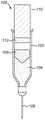
图1示出了具有缓冲器的注射装置的示意性例子;Figure 1 shows a schematic example of an injection device with a buffer;
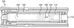
图2a至图2c示出了包括可缩回尖端的注射装置缓冲器的实施方案;Figures 2a to 2c illustrate an embodiment of an injection device bumper comprising a retractable tip;
图3示出了在包含不同药剂量的注射装置中的可缩回尖端缓冲器的例子;Figure 3 shows an example of a retractable tip bumper in an injection device containing different doses of medicament;
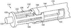
图4a至图4c示出了包括可缩回尖端的注射装置缓冲器的替代实施方案;Figures 4a to 4c illustrate an alternative embodiment of an injection device bumper comprising a retractable tip;
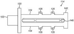
图5a至图5c展示了用于缓冲器的可缩回尖端的示例实施方案;Figures 5a-5c illustrate an example embodiment of a retractable tip for a bumper;
图6a至图6c展示了可缩回尖端缓冲器的替代实施方案;Figures 6a-6c illustrate an alternative embodiment of a retractable tip bumper;
图7示出了用于衰减撞击力的可缩回尖端的另外的例子;Figure 7 shows a further example of a retractable tip for attenuating impact force;
图8示出了具有用于衰减撞击力的弹簧的可缩回尖端的例子;Figure 8 shows an example of a retractable tip with a spring for damping impact force;
图9示出了具有泡沫塞的注射装置缓冲器的实施方案;Figure 9 shows an embodiment of an injection device bumper with a foam plug;
图10示出了与泡沫塞一起使用的柱塞主体的实施方案;Figure 10 shows an embodiment of a plunger body for use with a foam plug;
图11示出了与泡沫塞兼容的柱塞尖端的实施方案;Figure 11 shows an embodiment of a plunger tip compatible with a foam plug;
图12示出了具有唇形密封件的注射装置缓冲器的实施方案;以及Figure 12 shows an embodiment of an injection device bumper with a lip seal; and
图13a至图13c示出了具有柔性臂的注射装置缓冲器的实施方案。Figures 13a-13c illustrate an embodiment of an injection device bumper with flexible arms.
具体实施方式Detailed ways
图1示出了具有缓冲器的注射装置的示意性例子。Figure 1 shows a schematic example of an injection device with a buffer.
注射装置100包括用于保持药剂104的药剂容器102。在一些实施方案中,药剂容器102形成(例如,用于一注装置的)注射筒的一部分。在其他实施方案中,药剂容器102形成自动注射器的一部分。在这种情况下,药剂容器102可以是能够根据需要而更换的自动注射器的可消耗零部件。在所示的实施方案中,药剂容器102的壁基本上是圆柱形的。通常,药剂容器可以具有不同的截面形状。在以下描述中,药剂容器102总体上将被描述为药剂筒。然而,可以替代性地使用药剂容器102的其他例子。
注射装置1进一步包括针106,药剂104可以经由所述针从药剂筒102排出。在一些实施方案中,针106是药剂筒102的一体部分。在下文中,注射装置100的针106端将被称为远端,而注射100装置的相反端被称为近端。The injection device 1 further comprises a
塞子108可平移地设置在药剂筒102的壁之间。塞子108可在药剂筒102的轴向方向上平移。The
提供柱塞110(本文中也被称为柱塞杆),所述柱塞可以下压到药剂筒102中,以便经由针106来排出药剂104。柱塞110可在药剂筒102的轴向方向上移位。在朝向药剂筒102的远端下压时,柱塞110起作用来使塞子108朝向针106移位,由此经由针106从药剂筒102排出药剂104。在使用自动注射器的实施方案中,柱塞110被安装在自动注射器动力组(powerpack)中和/或由自动注射器动力组驱动。柱塞110还可以是弹簧驱动的。A plunger 110 (also referred to herein as a plunger rod) is provided which can be depressed into the
缓冲器112被设置在柱塞上。缓冲器112起作用来减小当柱塞110被下压时柱塞110接触塞子108的冲击。在所示的实施方案中,缓冲器被提供作为柱塞110的一部分,但是在替代实施方案中,所述缓冲器可以被提供作为塞子108的一部分或作为单独部件。下文将描述缓冲器112的示例实施方案。在一些实施方案中,缓冲器与柱塞110同轴。A
在使用中,柱塞110朝向药剂筒102的远端下压。这在注射筒的情况下由用户手动地完成的,其中用户使用其手指来下压柱塞110。在自动注射器实施方案中,柱塞110的下压是例如使用驱动机构(诸如弹簧或马达)自动实现的。驱动机构可以致动柱塞110以将柱塞110下压到药剂筒中。In use, the
在任一类型的实施方案中,柱塞110的下压导致柱塞110与塞子108相接触。柱塞110的进一步下压将导致塞子108沿着药剂筒102朝向针106轴向移位。这致使药剂筒102中的药剂104从针106排出。In either type of embodiment, depression of the
在柱塞110与塞子108之间的初始接触可能导致冲击。在由柱塞杆110使塞子108移位的过程中,缓冲器112接触塞子108,由此减小在柱塞杆110与塞子108之间的撞击力,并因此减小冲击。这可以改善用户体验,并且减少注射筒破裂和/或部件变形。Initial contact between the
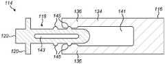
图2a至图2c示出了包括可缩回尖端114的注射装置缓冲器112的实施方案。图2a示出了处于伸出构型的可缩回尖端114,而图2b示出了处于收缩构型的可缩回尖端114。图2c示出了移除了可缩回尖端的柱塞主体116。2a-2c illustrate an embodiment of an
缓冲器112包括可缩回尖端114,所述可缩回尖端可收缩到柱塞110的柱塞主体116中。在所示的例子中,柱塞主体116是圆柱形的,尽管许多其他的形状也是可能的。The
可缩回尖端114包括在轴向方向上伸长的尖端本体118。端板120(在这个例子中是圆柱形的)和接触表面122被设置在可缩回尖端114的远端处。在柱塞110的操作期间,接触表面122接触塞子108。在一些实施方案中,接触表面122呈从端板120伸出的突起的形式。然而,接触表面122可以替代性地由端板120本身形成。The
一个或多个带齿梁124在轴向方向上从端板120沿着尖端本体118的外侧朝向注射装置的近端延伸。带齿梁124各自包括一个或多个齿126。在一些实施方案(未示出)中,齿126可以朝向柱塞110的近端斜切。在所示的实施方案中,尖端本体118具有两个带齿梁124,各个带齿梁被设置在尖端本体118的与彼此相对的一侧上。One or more
在一些实施方案中,中心圆柱形杆128从端板120的中心轴向地延伸。中心杆128可以起作用来将可缩回尖端114引导到柱塞主体116中。In some embodiments, a central
在一些实施方案中,带齿梁124和/或中心杆128可以与端板120一体地形成。替代性地,带齿梁124和/或中心杆128可以被制造为随后附接到端板的单独部件。In some embodiments,
柱塞主体116包括一个或多个接收部130。在所示的实施方案中,提供了两个接收部130,在柱塞主体116的两个相对侧中的每一侧上各一个。每个接收部包括一个凹槽132,可缩回尖端114的带齿梁124可以被接收到所述凹槽中。接收部130各自包括具有一个或多个接合齿136的可偏转臂134。在一些实施方案中,接合齿136朝向柱塞主体116的远端斜切。The
在一些实施方案中,柱塞主体包括中心孔138,可缩回尖端的中心圆柱形杆128被接收在所述中心孔中。中心孔138与中心杆128的组合可以起作用来在可缩回尖端的缩回过程中将可缩回尖端114引导到柱塞主体116中。In some embodiments, the plunger body includes a
在使用中,柱塞110被轴向下压到药剂筒102中并且经由可缩回尖端114的接触表面122与塞子108相接触。当塞子108与药剂筒102壁的摩擦被克服时,可缩回尖端114通过可缩回尖端114上的合力朝向柱塞主体116推动。可缩回尖端114的齿126因此被推动抵靠在可偏转臂134的接合齿136上。这可以致使可偏转臂134偏转,从而允许可缩回尖端114缩回到柱塞主体116中。可偏转臂134的偏转和在可缩回尖端本体118与柱塞主体116之间的摩擦起作用来吸收柱塞110在塞子108上的撞击的一些冲击。In use, the
图3示出了在包含不同药剂量的注射装置中的可缩回尖端缓冲器的例子。Figure 3 shows an example of a retractable tip bumper in an injection device containing different doses of medicament.
在各个例子中,注射装置100配备有填充有不同量的药剂104的药剂筒102。在所示的例子中,注射装置是自动注射器。柱塞主体116具有在注射装置100中的标准初始位置。然而,可缩回尖端114可以取决于塞子108在药剂筒108内的位置来定位在不同的伸出位置处。可以通过改变已经经过接合齿136进入柱塞主体116中的齿126的初始数量来改变可缩回尖端114的初始位置。In various examples,
每个药剂筒中的不同量的药剂导致在每个药剂筒102内塞子108处于不同的初始位置处。可缩回尖端114可以被初始地定位,以便改变初始的塞子-柱塞间隙140。可以在注射装置100的组装过程中设定可缩回尖端114的初始定位。替代性地,可以在将药剂筒102安装到注射装置100中的过程中将其设定。The different amounts of medicament in each cartridge result in the
图4a至图4c示出了包括可缩回尖端114的注射装置缓冲器112的替代实施方案。所述实施方案共享关于图2a至图2c以及图3a至图3d所描述的实施方案的许多特征。4a to 4c illustrate an alternative embodiment of an
缓冲器112包括可缩回尖端114,所述可缩回尖端可收缩到柱塞110的柱塞主体116中。在所示的例子中,柱塞主体116是圆柱形的,尽管许多其他的形状也是可能的。The
可缩回尖端114包括在轴向方向上伸长的尖端本体118。端板120(在这个例子中是圆柱形的)和接触表面122被设置在可缩回尖端114的远端处,如关于图2a至图2c中的实施方案所描述的。The
一个或多个带齿梁124在轴向方向上从端板120沿着尖端本体118的外侧朝向注射装置的近端延伸。带齿梁124各自包括一个或多个齿126。在所示的实施方案中,齿126朝向柱塞110的近端斜切。在所示的实施方案中,尖端本体118具有两个带齿梁124,各个带齿梁被设置在尖端本体118的与彼此相对的一侧上。One or more
可缩回尖端114进一步包括用于将可缩回尖端114保持在柱塞主体116中的端板142。柱塞尖端114可以组装在柱塞主体116中。The
在一些实施方案中,中心圆柱形杆128从端板120的中心轴向地延伸。中心杆128可以起作用来将可缩回尖端114引导到柱塞主体116中。In some embodiments, a central
在一些实施方案中,带齿梁124和/或中心杆128可以与端板120一体地形成。替代性地,带齿梁124和/或中心杆128可以被制造为随后附接到端板的单独部件。In some embodiments,
柱塞主体116包括接收部130。接收部130各自包括具有一个或多个接合齿146的刚性臂144。在一些实施方案中,接合齿136朝向柱塞主体116的远端斜切。The
在一些实施方案中,柱塞主体包括中心孔138,可缩回尖端的中心圆柱形杆128被接收在所述中心孔中。中心孔138与中心杆128的组合可以起作用来在可缩回尖端的缩回过程中将可缩回尖端114引导到柱塞主体116中。In some embodiments, the plunger body includes a
在使用中,柱塞110被轴向下压到药剂筒102中并且经由可缩回尖端114的接触表面122与塞子108相接触。当塞子108与药剂筒102壁的摩擦被克服时,可缩回尖端114通过可缩回尖端114上的合力朝向柱塞主体116推动。可缩回尖端114的齿126因此被推动抵靠在臂144的接合齿146上。这可以致使柱塞尖端114的梁124偏转,从而允许可缩回尖端114缩回到柱塞主体116中。臂124的偏转和在可缩回尖端本体118与柱塞主体116之间的摩擦起作用来吸收柱塞110在塞子108上的撞击的一些冲击。In use, the
由可缩回尖端114提供的阻尼量可以以多种方式改变。例如,可以改变可缩回尖端114的初始位置,使得一个或多个齿126已经位于柱塞主体116中,如例如在图4b中所示。The amount of damping provided by the
替代性地或除此之外,可通过改变可缩回尖端114的一个或多个特性来改变阻尼效果,如例如在图4c中所示。例如,可增大或减小臂124的厚度和/或刚度。在另一个例子中,系杆146可被放置在臂124之间以限制臂124的柔性。Alternatively or in addition, the damping effect may be varied by varying one or more properties of the
也可以改变齿126的特性以改变阻尼效果。例如,可以增大或减小齿126的高度,以相应地增大或减小对可缩回尖端114运动的阻力。在齿126上的任何斜切的坡度角可以变化。在可缩回尖端114与柱塞主体116之间的摩擦量可以通过改变可缩回尖端114或柱塞主体116中的一者或多者的表面性质而改变。例如,可以改变可缩回尖端114和/或柱塞主体116的表面粗糙度。The characteristics of the
可以通过平衡若干机械特性(例如抗冲击性、韧性(诸如Charpy/Izod)和挠曲模量)来影响材料的选择,以选择具有期望的能量吸收特性和刚度(以增加摩擦)并且具有足够的抗断裂性的材料。The choice of material can be influenced by balancing several mechanical properties such as impact resistance, toughness (such as Charpy/Izod), and flexural modulus to select materials with desired energy absorption properties and stiffness (to increase friction) and have sufficient Break-resistant material.
图5a至图5c展示了用于缓冲器的可缩回尖端的示例实施方案。图5a示出了如关于图4a至图4c所描述的可缩回尖端114。Figures 5a-5c illustrate an example embodiment of a retractable tip for a bumper. Figure 5a shows the
图5b示出了具有设置在中心杆128上的固位特征148的可缩回尖端114。可缩回尖端114是关于图4a至图4c描述的可缩回尖端114的变型,其中将固位特征148添加到中心杆128。通过限制中心杆128穿过中心孔138的运动,固位特征148可以起作用来将可缩回尖端114保持在柱塞主体116中。在所示的实施方案中,固位特征包括从中心杆128伸出的两个突起147,尽管通常可使用多个突起147。在一些例子中,中心杆128包括在突起147之间的延伸到中心杆128的近端的切开区段149。这允许将可缩回尖端114插入到柱塞主体116上。FIG. 5 b shows the
图5c示出了在臂124与柱塞槽之间具有燕尾锥形配件150的可缩回尖端。可缩回尖端114是关于图4a至图4c描述的可缩回尖端114的变型。燕尾配件150起作用来防止阻尼器臂124相对于柱塞主体116径向脱离。这可以改进稳定性,因为臂124和柱塞主体116的轴向对准角更可能一致。燕尾配件150还可以确保阻尼器的臂在压缩期间保持对准,并且它们不会挠曲到柱塞轮廓的外径之外。此外,燕尾配件150可以改进撞击过程中的运动的一致性。Figure 5c shows a retractable tip with a dovetail taper fitting 150 between the
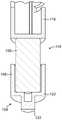
图6a至图6c展示了可缩回尖端缓冲器的替代实施方案。图6a示出了处于伸出构型的可缩回尖端114。图6b示出了处于部分缩回构型的可缩回尖端114。图6c示出了处于完全缩回构型的可缩回尖端114。Figures 6a-6c illustrate an alternative embodiment of a retractable tip bumper. Figure 6a shows the
在这个实施方案中,柱塞配备有可偏转侧壁,每个可偏转侧壁包括可偏转臂134和向内指向柱塞主体116的中心孔141中的一个或多个接合齿136。接合齿136朝向中心孔141的远端定位。中心孔接收可缩回尖端114的本体118。In this embodiment, the plunger is equipped with deflectable side walls each comprising a
可缩回尖端114包括端板120和接触表面122,如以上关于图2所描述的。尖端本体118从端板120轴向地延伸。尖端本体118被布置成由柱塞主体116的中心孔141接收。一个或多个突起145从尖端本体118径向地延伸。在中心孔141的开口中,突起145延伸至的半径大于由接合齿136形成的半径。在一些实施方案中,尖端本体118包括中空部分143。The
在使用中,随着接触表面122与注射装置100的塞子108进行接触,可缩回尖端114朝向柱塞主体116推动。突起145被推动抵靠在接合齿136上,从而致使可偏转臂134向外偏转,从而允许可缩回尖端114缩回到柱塞主体116中。可偏转臂134的偏转和在可缩回尖端本体118与柱塞主体116之间的摩擦起作用来吸收柱塞110在塞子108上的撞击的一些冲击。In use, the
在一些替代实施方案中,可偏转臂134被替换为不偏转的加强臂。替代地,齿136/可缩回尖端114的突起145是可变形的,并且随着可缩回尖端114缩回到柱塞主体116中而变形。在撞击时,齿136在穿过开口进入柱塞本体116中时变形。材料的变形吸收撞击能量。关于这些实施方案,齿136还可以被描述为可压缩突起。In some alternative embodiments, the
在这些实施方案中,可缩回尖端114包括坚韧但具有低脆性的材料。可以通过改变可缩回尖端114在柱塞主体116内的初始位置来改变阻尼程度。替代性地或除此之外,可以改变可缩回尖端114和/或柱塞主体116的一个或多个特性,如例如关于图4c所描述的。In these embodiments, the
图7示出了用于衰减撞击力的可缩回尖端114的另外的例子。在这个实施方案中,使用完全缩回的尖端114来进一步衰减撞击力。可缩回尖端114的臂124可以在柱塞110与塞子108撞击时变形。在轴向载荷152下,臂124将弹性地屈曲,从而吸收一些撞击能量。FIG. 7 shows an additional example of a
当不再施加轴向力时,例如因为注射装置100已经到达剂量结束,可缩回尖端115的臂124将返回到其原始位置,因为由于偏转引起的臂124上的力大于静态力。这可以确保柱塞110的长度在剂量结束时保持一致,由此确保已经递送了正确的剂量。When the axial force is no longer applied, for example because the
图8示出了具有用于衰减撞击力的弹簧机构154的可缩回尖端114的例子。在这个实施方案中,使用完全缩回的尖端114来进一步衰减撞击力。可缩回尖端114包括弹簧机构154。在将轴向载荷152施加到柱塞尖端122时,弹簧机构152另外提供撞击吸收。在所示的例子中,弹簧机构154包括围绕可缩回尖端114的外侧布置的多个可压缩单元155。可以使用其他类型的弹簧机构154,例如螺旋弹簧。FIG. 8 shows an example of a
图9示出了具有泡沫塞的注射装置缓冲器的实施方案。Figure 9 shows an embodiment of an injection device bumper with a foam plug.
在缓冲器112的这个实施方案中,提供了包括端板120和接触表面122的尖端154。尖端154进一步包括侧壁156,所述侧壁与端板120一起限定空腔,所述空腔在所示出的例子中是圆柱形的。In this embodiment of the
泡沫塞158被定位在柱塞主体116与尖端154之间。泡沫塞158包括刚性泡沫阻尼器,所述刚性泡沫阻尼器在接收尖端154与塞子108的撞击下将塑性变形。泡沫塞158经由空腔由尖端154接收。A
图10示出了与泡沫塞一起使用的柱塞主体的实施方案。Figure 10 shows an embodiment of a plunger body for use with a foam plug.
柱塞主体116包括主体尖端160。主体尖端160包括用于保持泡沫塞158的凹陷162。The
图11示出了柱塞尖端154的实施方案。在这个实施方案中,柱塞尖端154在柱塞尖端154的远端处配备有泡沫尖端157。泡沫尖端157包括刚性泡沫阻尼器,所述刚性泡沫阻尼器在柱塞尖端154与塞子108的撞击下将变形,由此吸收冲击。FIG. 11 shows an embodiment of a
图12示出了具有密封唇缘的注射装置缓冲器的实施方案。Figure 12 shows an embodiment of an injection device bumper with a sealing lip.
在缓冲器112的这个实施方案中,柱塞主体116包括密封唇缘164。密封唇缘164围绕柱塞主体116的圆周延伸。密封唇缘164被设置在柱塞主体116的远端处或附近。在使用中,密封唇缘164与药剂筒的筒管形成基本上气密的密封。In this embodiment of
在所示的例子中,密封唇缘164被模制到柱塞中,从而形成柱塞主体116的一体部分。然而,密封唇缘164可以替代性地或除此之外地包括附接到柱塞主体116的单独的柔性部件,例如由柱塞主体116中的凹陷接收的O形环。In the example shown, the sealing lip 164 is molded into the plunger so as to form an integral part of the
柱塞主体116进一步包括在柱塞主体前板168上的排气孔口或孔166。排气孔口通向柱塞主体116的中空内部170,并且将中空内部170流体地连接到柱塞主体170的外部。The
在使用中,随着柱塞被下压,柱塞-塞子间隙中的空气被柱塞主体前板168压缩,并且流过排气孔口166进入柱塞主体116的中空内部170。然而,空气从柱塞-塞子间隙进入中空内部170的流动受到排气孔口166的直径的限制。这致使柱塞-塞子间隙中的压力增加,由此充当气垫以减少柱塞110对塞子108的冲击。In use, as the plunger is depressed, air in the plunger-plug gap is compressed by the plunger
图13a至图13c示出了具有柔性臂的注射装置缓冲器的实施方案。Figures 13a-13c illustrate an embodiment of an injection device bumper with flexible arms.
在这个实施方案中,柱塞主体116包括弯曲凹部172。弯曲凹部172的壁包括一个或多个凹口174。凹口174被布置成产生随着可缩回尖端缩回而用于可缩回尖端114的柔性臂176的一个或多个停止位置。In this embodiment, the
可缩回尖端114被设置为包括端板120和接触表面122,如以上关于图2所描述的。柔性臂176在轴向方向上从端板120延伸。在所示的实施方案中,柔性臂176从端板120的偏离中心点延伸。柔性臂176终止于指向凹口174方向的头部178。The
在使用中,柱塞110朝向药剂筒102中的塞子108下压。随着接触表面122接触药剂筒102中的塞子108,可缩回尖端114被推入弯曲凹部172中,从而致使其缩回到柱塞主体116中。随着可缩回尖端缩回,头部178沿着弯曲凹部172的内部延伸,从而随着可缩回尖端114缩回而致使柔性臂176弯曲。这提供了抵抗柱塞在塞子上的撞击力的力。In use, the
随着头部178沿着弯曲凹部172的内部延伸,头部将落入弯曲凹部172的凹口174中。凹口174为头部178提供停止点,所述停止点对撞击产生额外的阻力。As the
应理解的是,缓冲器的以上实施方案中的一个或多个可以组合在单个注射装置中。It will be appreciated that one or more of the above embodiments of the buffer may be combined in a single injection device.
术语“药物”或“药剂”在本文中同义使用,并且描述了如下药学制剂,其含有一种或多种活性药物成分或其药学上可接受的盐或溶剂化物以及任选地药学上可接受的载剂。从最广义上来说,活性药学成分(“API”)是对人或动物具有生物学效应的化学结构。在药理学中,将药物或药剂用于治疗、治愈、预防或诊断疾病或者用于以其他方式增强身体或精神健康。可以将药物或药剂使用有限的持续时间,或者定期用于慢性障碍。The term "drug" or "medicament" is used synonymously herein and describes a pharmaceutical formulation containing one or more active pharmaceutical ingredients or a pharmaceutically acceptable salt or solvate thereof and optionally a pharmaceutically acceptable Accepted carrier. In the broadest sense, an active pharmaceutical ingredient ("API") is a chemical structure that has a biological effect on humans or animals. In pharmacology, the use of drugs or agents to treat, cure, prevent, or diagnose disease or to otherwise enhance physical or mental health. The drug or agent may be used for a limited duration, or on a regular basis for a chronic disorder.
如下文所述,药物或药剂可以包括用于治疗一种或多种疾病的在各种类型的制剂中的至少一种API或其组合。API的例子可以包括小分子(具有500Da或更小的分子量);多肽、肽和蛋白质(例如,激素、生长因子、抗体、抗体片段和酶);碳水化合物和多糖;以及核酸、双链或单链DNA(包括裸露和cDNA)、RNA、反义核酸诸如反义DNA和RNA、小干扰RNA(siRNA)、核酶、基因和寡核苷酸。可以将核酸掺入分子递送系统(诸如载体、质粒或脂质体)中。还考虑了一种或多种药物的混合物。As described below, a drug or medicament may include at least one API or a combination thereof in various types of formulations for the treatment of one or more diseases. Examples of APIs may include small molecules (having a molecular weight of 500 Da or less); polypeptides, peptides, and proteins (e.g., hormones, growth factors, antibodies, antibody fragments, and enzymes); carbohydrates and polysaccharides; Stranded DNA (including naked and cDNA), RNA, antisense nucleic acids such as antisense DNA and RNA, small interfering RNA (siRNA), ribozymes, genes, and oligonucleotides. Nucleic acids can be incorporated into molecular delivery systems such as vectors, plasmids or liposomes. Mixtures of one or more drugs are also contemplated.
可以将药物或药剂容纳在适配为用于药物递送装置的初级包装或“药物容器”中。药物容器可以是例如筒、注射筒、储器或其他坚固或柔性的器皿,其被配置成提供用于储存(例如,短期或长期储存)一种或多种药物的合适腔室。例如,在一些情况下,可以将腔室设计成将药物储存至少一天(例如,1天到至少30天)。在一些情况下,可以将腔室设计成将药物储存约1个月至约2年。可以在室温(例如,约20℃)或冷藏温度(例如,从约-4℃至约4℃)下进行储存。在一些情况下,药物容器可以是或可以包括双腔室筒,其被配置为单独储存待给予的药学制剂的两种或更多种组分(例如,API和稀释剂、或两种不同的药物),每个腔室中存储一种。在这种情况下,双腔室筒的两个腔室可以被配置成在分配到人体或动物体内之前和/或期间允许两种或更多种成分之间的混合。例如,两个腔室可以被配置为使得它们彼此处于流体连通(例如,通过两个腔室之间的导管),并且允许用户在分配之前在需要时混合两种组分。替代性地或除此之外,两个腔室可以被配置成允许在将组分分配到人体或动物体内时进行混合。The drug or medicament may be contained in a primary packaging or "drug container" adapted for use in a drug delivery device. A drug container may be, for example, a barrel, syringe, reservoir, or other solid or flexible vessel configured to provide a suitable chamber for storage (eg, short-term or long-term storage) of one or more drugs. For example, in some cases, the chamber can be designed to store the drug for at least one day (eg, 1 day to at least 30 days). In some cases, the chamber can be designed to store the drug for about 1 month to about 2 years. Storage can be at room temperature (eg, about 20°C) or refrigerated temperature (eg, from about -4°C to about 4°C). In some cases, the drug container can be or include a dual chamber cartridge configured to separately store two or more components of a pharmaceutical formulation to be administered (e.g., an API and a diluent, or two different Drugs), one stored in each chamber. In this case, the two chambers of the dual chamber cartridge may be configured to allow mixing between the two or more components prior to and/or during dispensing into the human or animal body. For example, the two chambers may be configured such that they are in fluid communication with each other (eg, via a conduit between the two chambers) and allow the user to mix the two components if desired prior to dispensing. Alternatively or in addition, the two chambers may be configured to allow mixing when dispensing the components into the human or animal body.
本文所述的药物递送装置中容纳的药物或药剂可用于治疗和/或预防许多不同类型的医学疾病。障碍的例子包括例如糖尿病或与糖尿病相关的并发症(诸如糖尿病视网膜病变)、血栓栓塞障碍(诸如深静脉或肺血栓栓塞)。障碍的另外例子是急性冠状动脉综合征(ACS)、心绞痛、心肌梗塞、癌症、黄斑变性、炎症、枯草热、动脉粥样硬化和/或类风湿性关节炎。API和药物的例子是如以下手册中所述的那些:诸如Rote Liste 2014(例如但不限于,主要组(main group)12(抗糖尿病药物)或86(肿瘤药物))和Merck Index,第15版。Drugs or agents contained in the drug delivery devices described herein can be used to treat and/or prevent many different types of medical conditions. Examples of disorders include eg diabetes or complications associated with diabetes such as diabetic retinopathy, thromboembolic disorders such as deep vein or pulmonary thromboembolism. Further examples of disorders are acute coronary syndrome (ACS), angina pectoris, myocardial infarction, cancer, macular degeneration, inflammation, hay fever, atherosclerosis and/or rheumatoid arthritis. Examples of APIs and drugs are those as described in handbooks such as Rote Liste 2014 (for example, but not limited to, main group 12 (antidiabetic drugs) or 86 (oncology drugs)) and Merck Index, No. 15 Version.
用于治疗和/或预防1型或2型糖尿病或与1型或2型糖尿病相关的并发症的API的例子包括胰岛素(例如人胰岛素、或人胰岛素类似物或衍生物);胰高血糖素样肽(GLP-1)、GLP-1类似物或GLP-1受体激动剂、或其类似物或衍生物;二肽基肽酶-4(DPP4)抑制剂、或其药学上可接受的盐或溶剂化物;或其任何混合物。如本文所用,术语“类似物”和“衍生物”是指具有如下分子结构的多肽,所述分子结构可以通过缺失和/或交换在天然存在的肽中存在的至少一个氨基酸残基和/或通过添加至少一个氨基酸残基而在形式上衍生自天然存在的肽的结构(例如人胰岛素的结构)。所添加和/或交换的氨基酸残基可以是可编码氨基酸残基或其他天然残基或纯合成氨基酸残基。胰岛素类似物还被称为“胰岛素受体配体”。特别地,术语“衍生物”是指具有如下分子结构的多肽,所述分子结构在形式上可以衍生自天然存在的肽的结构(例如人胰岛素的结构),其中一个或多个有机取代基(例如脂肪酸)与一个或多个氨基酸结合。任选地,天然存在的肽中存在的一个或多个氨基酸可能已被缺失和/或被其他氨基酸(包括不可编码的氨基酸)替代,或者氨基酸(包括不可编码的氨基酸)已被添加到天然存在的肽中。Examples of APIs useful in the treatment and/or prevention of type 1 or type 2 diabetes or complications associated with type 1 or type 2 diabetes include insulin (e.g. human insulin, or human insulin analogs or derivatives); glucagon Peptide-like peptide (GLP-1), GLP-1 analog or GLP-1 receptor agonist, or analog or derivative thereof; dipeptidyl peptidase-4 (DPP4) inhibitor, or its pharmaceutically acceptable salt or solvate; or any mixture thereof. As used herein, the terms "analogue" and "derivative" refer to a polypeptide having a molecular structure that can be modified by deletion and/or exchange of at least one amino acid residue present in a naturally occurring peptide and/or Formally derived from the structure of a naturally occurring peptide (eg the structure of human insulin) by the addition of at least one amino acid residue. The added and/or exchanged amino acid residues may be codable amino acid residues or other natural residues or purely synthetic amino acid residues. Insulin analogs are also known as "insulin receptor ligands". In particular, the term "derivative" refers to a polypeptide having a molecular structure that can be formally derived from that of a naturally occurring peptide (such as that of human insulin) in which one or more organic substituents ( such as fatty acids) in combination with one or more amino acids. Optionally, one or more amino acids present in the naturally occurring peptide may have been deleted and/or replaced by other amino acids (including non-codable amino acids), or amino acids (including non-codable amino acids) have been added to the naturally occurring of the peptides.
胰岛素类似物的例子是Gly(A21)、Arg(B31)、Arg(B32)人胰岛素(甘精胰岛素);Lys(B3)、Glu(B29)人胰岛素(谷赖胰岛素);Lys(B28)、Pro(B29)人胰岛素(赖脯胰岛素);Asp(B28)人胰岛素(门冬胰岛素);人胰岛素,其中在位置B28处的脯氨酸被Asp、Lys、Leu、Val或Ala替代并且其中在位置B29处的Lys可以被Pro替代;Ala(B26)人胰岛素;Des(B28-B30)人胰岛素;Des(B27)人胰岛素和Des(B30)人胰岛素。Examples of insulin analogues are Gly(A21), Arg(B31), Arg(B32) human insulin (insulin glargine); Lys(B3), Glu(B29) human insulin (insulin glulisine); Lys(B28), Pro(B29) human insulin (insulin lispro); Asp(B28) human insulin (insulin aspart); human insulin, wherein the proline at position B28 is replaced by Asp, Lys, Leu, Val or Ala and wherein in Lys at position B29 can be replaced by Pro; Ala(B26) human insulin; Des(B28-B30) human insulin; Des(B27) human insulin and Des(B30) human insulin.
胰岛素衍生物的例子是例如B29-N-肉豆蔻酰-des(B30)人胰岛素,Lys(B29)(N-十四酰)-des(B30)人胰岛素(地特胰岛素,

GLP-1、GLP-1类似物和GLP-1受体激动剂的例子是例如利西拉肽


寡核苷酸的例子是例如:米泊美生钠
DPP4抑制剂的例子是维达列汀、西他列汀、地那列汀(Denagliptin)、沙格列汀、小檗碱。Examples of DPP4 inhibitors are vildagliptin, sitagliptin, denagliptin, saxagliptin, berberine.
激素的例子包括垂体激素或下丘脑激素或调节活性肽及其拮抗剂,诸如促性腺激素(促滤泡素、促黄体素、绒毛膜促性腺激素、促生育素)、促生长激素(Somatropine)(生长激素)、去氨加压素、特利加压素、戈那瑞林、曲普瑞林、亮丙瑞林、布舍瑞林、那法瑞林和戈舍瑞林。Examples of hormones include pituitary or hypothalamic hormones or regulatory active peptides and their antagonists, such as gonadotropins (follicle-stimulating hormone, luteinizing hormone, chorionic gonadotropin, tocotropin), growth-stimulating hormone (Somatropine) (somatorelin), desmopressin, terlipressin, gonadorelin, triptorelin, leuprolide, buserelin, nafarelin, and goserelin.
多糖的例子包括葡糖胺聚糖(glucosaminoglycane)、透明质酸、肝素、低分子量肝素或超低分子量肝素或其衍生物、或硫酸化多糖(例如上述多糖的多硫酸化形式)、和/或其药学上可接受的盐。多硫酸化低分子量肝素的药学上可接受的盐的例子是依诺肝素钠。透明质酸衍生物的例子是Hylan G-F20
如本文所用,术语“抗体”是指免疫球蛋白分子或其抗原结合部分。免疫球蛋白分子的抗原结合部分的例子包括F(ab)和F(ab')2片段,其保留结合抗原的能力。抗体可以是多克隆抗体、单克隆抗体、重组抗体、嵌合抗体、去免疫或人源化抗体、完全人抗体、非人(例如鼠类)抗体或单链抗体。在一些实施方案中,抗体具有效应子功能,并且可以固定补体。在一些实施方案中,抗体具有降低的或没有结合Fc受体的能力。例如,抗体可以是同种型或亚型、抗体片段或突变体,其不支持与Fc受体的结合,例如,它具有诱变的或缺失的Fc受体结合区。术语抗体还包括基于四价双特异性串联免疫球蛋白(TBTI)的抗原结合分子和/或具有交叉结合区取向(CODV)的双可变区抗体样结合蛋白。As used herein, the term "antibody" refers to an immunoglobulin molecule or an antigen-binding portion thereof. Examples of antigen-binding portions of immunoglobulin molecules include F(ab) and F(ab')2 fragments, which retain the ability to bind antigen. Antibodies can be polyclonal, monoclonal, recombinant, chimeric, deimmunized or humanized, fully human, non-human (eg, murine) or single chain antibodies. In some embodiments, the antibody has effector function and can fix complement. In some embodiments, the antibody has reduced or no ability to bind Fc receptors. For example, an antibody may be an isotype or subtype, antibody fragment or mutant that does not support binding to an Fc receptor, eg, that has a mutagenized or deleted Fc receptor binding region. The term antibody also includes tetravalent bispecific tandem immunoglobulin (TBTI) based antigen binding molecules and/or dual variable domain antibody-like binding proteins with cross-binding domain orientation (CODV).
术语“片段”或“抗体片段”是指衍生自抗体多肽分子的多肽(例如,抗体重链和/或轻链多肽),其不包括全长抗体多肽,但仍包括能够结合抗原的全长抗体多肽的至少一部分。抗体片段可包括全长抗体多肽的切割部分,尽管所述术语不限于此类切割片段。可用于本发明的抗体片段包括例如Fab片段、F(ab')2片段,scFv(单链Fv)片段、线性抗体、单特异性或多特异性抗体片段(诸如双特异性、三特异性、四特异性和多特异性抗体(例如,双链抗体、三链抗体、四链抗体))、单价或多价抗体片段(诸如二价、三价、四价和多价抗体)、微型抗体、螯合重组抗体、三抗体或双抗体、胞内抗体、纳米抗体,小模块化免疫药物(SMIP)、结合域免疫球蛋白融合蛋白、骆驼化抗体和含有VHH的抗体。抗原结合抗体片段的另外的例子在本领域中是已知的。The terms "fragment" or "antibody fragment" refer to polypeptides derived from antibody polypeptide molecules (e.g., antibody heavy and/or light chain polypeptides), which do not include full-length antibody polypeptides, but still include full-length antibodies capable of binding antigen at least a portion of a polypeptide. Antibody fragments may include cleaved portions of full-length antibody polypeptides, although the term is not limited to such cleaved fragments. Antibody fragments useful in the present invention include, for example, Fab fragments, F(ab')2 fragments, scFv (single chain Fv) fragments, linear antibodies, monospecific or multispecific antibody fragments (such as bispecific, trispecific, Tetraspecific and multispecific antibodies (e.g., diabodies, triabodies, tetrabodies)), monovalent or multivalent antibody fragments (such as bivalent, trivalent, tetravalent and multivalent antibodies), minibodies, Chelated recombinant antibodies, triabodies or diabodies, intrabodies, nanobodies, small modular immunopharmaceuticals (SMIPs), binding domain immunoglobulin fusion proteins, camelized antibodies, and VHH-containing antibodies. Additional examples of antigen-binding antibody fragments are known in the art.
术语“互补决定区”或“CDR”是指重链多肽和轻链多肽两者的可变区内的短多肽序列,其主要负责介导特异性抗原识别。术语“框架区”是指重链多肽和轻链多肽两者的可变区内的氨基酸序列,其不是CDR序列,并且主要负责维持CDR序列的正确定位以允许抗原结合。尽管框架区本身通常不直接参与抗原结合,如本领域中已知的,但是某些抗体的框架区内的某些残基可以直接参与抗原结合或可以影响CDR中的一个或多个氨基酸与抗原相互作用的能力。The term "complementarity determining region" or "CDR" refers to short polypeptide sequences within the variable regions of both heavy and light chain polypeptides that are primarily responsible for mediating specific antigen recognition. The term "framework region" refers to amino acid sequences within the variable regions of both heavy and light chain polypeptides that are not CDR sequences and are primarily responsible for maintaining the correct positioning of the CDR sequences to allow antigen binding. Although the framework regions themselves are generally not directly involved in antigen binding, as is known in the art, certain residues within the framework regions of certain antibodies may be directly involved in antigen binding or may affect the binding of one or more amino acids in the CDRs to the antigen. ability to interact.
抗体的例子是抗PCSK-9mAb(例如,阿利库单抗(Alirocumab))、抗IL-6mAb(例如,萨瑞鲁单抗(Sarilumab))和抗IL-4mAb(例如,度匹鲁单抗(Dupilumab))。Examples of antibodies are anti-PCSK-9 mAbs (e.g., Alirocumab), anti-IL-6 mAbs (e.g., Sarilumab) and anti-IL-4 mAbs (e.g., Dupilumab ( Dupilumab)).
本文所述的任何API的药学上可接受的盐也预期用于药物递送装置中的药物或药剂。药学上可接受的盐是例如酸加成盐和碱性盐。Pharmaceutically acceptable salts of any of the APIs described herein are also contemplated for use as a drug or medicament in a drug delivery device. Pharmaceutically acceptable salts are, for example, acid addition salts and basic salts.
本领域技术人员将理解,在不偏离本发明的全部范围和精神的情况下,可对本文所述的API、制剂、仪器、方法、系统和实施方案的各种组分/组件进行修改(添加和/或去除),本发明涵盖包括此类修改及其任何和所有等同物。Those skilled in the art will appreciate that modifications (additions) can be made to the various components/components of the APIs, formulations, apparatus, methods, systems and embodiments described herein without departing from the full scope and spirit of the invention. and/or removal), the present invention encompasses such modifications and any and all equivalents thereof.
Claims (13)
Applications Claiming Priority (3)
| Application Number | Priority Date | Filing Date | Title |
|---|---|---|---|
| EP18305479 | 2018-04-19 | ||
| EP18305479.0 | 2018-04-19 | ||
| PCT/EP2019/060198WO2019202130A1 (en) | 2018-04-19 | 2019-04-18 | Shock absorber for injection devices |
Publications (2)
| Publication Number | Publication Date |
|---|---|
| CN112312948A CN112312948A (en) | 2021-02-02 |
| CN112312948Btrue CN112312948B (en) | 2022-12-02 |
Family
ID=62091804
Family Applications (1)
| Application Number | Title | Priority Date | Filing Date |
|---|---|---|---|
| CN201980039376.4AActiveCN112312948B (en) | 2018-04-19 | 2019-04-18 | Buffers for injection devices |
Country Status (5)
| Country | Link |
|---|---|
| US (1) | US12233245B2 (en) |
| EP (1) | EP3781238A1 (en) |
| JP (1) | JP7324774B2 (en) |
| CN (1) | CN112312948B (en) |
| WO (1) | WO2019202130A1 (en) |
Families Citing this family (3)
| Publication number | Priority date | Publication date | Assignee | Title |
|---|---|---|---|---|
| CN117136083A (en)* | 2021-03-25 | 2023-11-28 | 美国安进公司 | drug delivery device |
| GB2622883A (en)* | 2022-09-30 | 2024-04-03 | Owen Mumford Ltd | Plunger and injection device |
| WO2024156428A1 (en)* | 2023-01-25 | 2024-08-02 | Shl Medical Ag | Plunger rod, sub-assembly and medicament delivery device |
Citations (3)
| Publication number | Priority date | Publication date | Assignee | Title |
|---|---|---|---|---|
| US3797489A (en)* | 1972-02-10 | 1974-03-19 | Survival Technology | Hypodermic injection device with shock absorbing spring |
| CN1658919A (en)* | 2002-05-02 | 2005-08-24 | Pa知识有限公司 | Injection device |
| CN102327657A (en)* | 2010-11-23 | 2012-01-25 | 房东森 | Safety injector |
Family Cites Families (9)
| Publication number | Priority date | Publication date | Assignee | Title |
|---|---|---|---|---|
| US5478314A (en)* | 1994-12-27 | 1995-12-26 | Malenchek; Robert | Non-reusable syringe |
| US7798993B2 (en) | 1998-07-29 | 2010-09-21 | Becton, Dickinson And Company | Single use syringe |
| MX2007007163A (en)* | 2004-12-21 | 2007-08-14 | Becton Dickinson Co | Syringe assembly having disabling mechanism. |
| CN201186086Y (en) | 2008-04-14 | 2009-01-28 | 翁天祥 | Amount-adjusting needleless injector |
| GB0913136D0 (en)* | 2009-07-28 | 2009-09-02 | Ucb Pharma Sa | Auto-injector |
| EP2583707A1 (en) | 2011-10-21 | 2013-04-24 | Sanofi-Aventis Deutschland GmbH | Auto-injector |
| MX388536B (en) | 2014-05-07 | 2025-03-20 | Amgen Inc | AUTO-INJECTOR WITH SHOCK-REDUCING ELEMENTS. |
| US10265476B2 (en)* | 2016-03-11 | 2019-04-23 | Shl Medical Ag | Two body syringe carrier assembly with dampener |
| MX2019015472A (en)* | 2017-06-22 | 2020-02-19 | Amgen Inc | Device activation impact/shock reduction. |
- 2019
- 2019-04-18CNCN201980039376.4Apatent/CN112312948B/enactiveActive
- 2019-04-18USUS17/048,007patent/US12233245B2/enactiveActive
- 2019-04-18WOPCT/EP2019/060198patent/WO2019202130A1/ennot_activeCeased
- 2019-04-18EPEP19718377.5Apatent/EP3781238A1/enactivePending
- 2019-04-18JPJP2020557211Apatent/JP7324774B2/enactiveActive
Patent Citations (3)
| Publication number | Priority date | Publication date | Assignee | Title |
|---|---|---|---|---|
| US3797489A (en)* | 1972-02-10 | 1974-03-19 | Survival Technology | Hypodermic injection device with shock absorbing spring |
| CN1658919A (en)* | 2002-05-02 | 2005-08-24 | Pa知识有限公司 | Injection device |
| CN102327657A (en)* | 2010-11-23 | 2012-01-25 | 房东森 | Safety injector |
Also Published As
| Publication number | Publication date |
|---|---|
| JP2021521908A (en) | 2021-08-30 |
| CN112312948A (en) | 2021-02-02 |
| US20210113775A1 (en) | 2021-04-22 |
| JP7324774B2 (en) | 2023-08-10 |
| WO2019202130A1 (en) | 2019-10-24 |
| EP3781238A1 (en) | 2021-02-24 |
| US12233245B2 (en) | 2025-02-25 |
Similar Documents
| Publication | Publication Date | Title |
|---|---|---|
| CN113853223B (en) | Drug delivery device and method for assembly | |
| US20240252761A1 (en) | Drug delivery device, plunger rod, set of plunger rods, method for assembling a drug delivery device and set of drug delivery devices | |
| US10940272B2 (en) | Feedback mechanism for a drug delivery device | |
| JP2023549898A (en) | Apparatus and drug delivery device for drug delivery devices | |
| JP2018520737A (en) | Drug delivery device | |
| JP2019516490A (en) | SEASLIMBA and its assembling method | |
| CN112312948B (en) | Buffers for injection devices | |
| CN112292167B (en) | Force reduction in an injection device | |
| US20230191029A1 (en) | Housing element and drug delivery device herewith | |
| US12303675B1 (en) | Medicament delivery device | |
| US20250041531A1 (en) | Assembly for an Injection Device and an Injection Device | |
| US20250041530A1 (en) | Assembly for an injection device, injection device comprising such an assembly, medicament container for such an assembly, and method for producing such a medicament container | |
| HK40048421B (en) | Force reduction in injection devices | |
| HK40048421A (en) | Force reduction in injection devices | |
| JP2023553696A (en) | Auto-injector using gas | |
| HK40084405B (en) | Housing element and drug delivery device herewith | |
| HK40084405A (en) | Housing element and drug delivery device herewith | |
| WO2024251799A1 (en) | Self-driven medicament container and medicament delivery device | |
| CN118785935A (en) | Workpiece carrier for injection molding |
Legal Events
| Date | Code | Title | Description |
|---|---|---|---|
| PB01 | Publication | ||
| PB01 | Publication | ||
| SE01 | Entry into force of request for substantive examination | ||
| SE01 | Entry into force of request for substantive examination | ||
| GR01 | Patent grant | ||
| GR01 | Patent grant |