CN112306150B - Man-machine interface device and switcher system - Google Patents
Man-machine interface device and switcher systemDownload PDFInfo
- Publication number
- CN112306150B CN112306150BCN201911147689.XACN201911147689ACN112306150BCN 112306150 BCN112306150 BCN 112306150BCN 201911147689 ACN201911147689 ACN 201911147689ACN 112306150 BCN112306150 BCN 112306150B
- Authority
- CN
- China
- Prior art keywords
- slide rail
- display unit
- rail
- switching piece
- fixing frame
- Prior art date
- Legal status (The legal status is an assumption and is not a legal conclusion. Google has not performed a legal analysis and makes no representation as to the accuracy of the status listed.)
- Active
Links
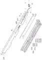
Images


Classifications
- G—PHYSICS
- G06—COMPUTING OR CALCULATING; COUNTING
- G06F—ELECTRIC DIGITAL DATA PROCESSING
- G06F1/00—Details not covered by groups G06F3/00 - G06F13/00 and G06F21/00
- G06F1/16—Constructional details or arrangements
- G06F1/1601—Constructional details related to the housing of computer displays, e.g. of CRT monitors, of flat displays
Landscapes
- Engineering & Computer Science (AREA)
- General Engineering & Computer Science (AREA)
- Theoretical Computer Science (AREA)
- Computer Hardware Design (AREA)
- Human Computer Interaction (AREA)
- Physics & Mathematics (AREA)
- General Physics & Mathematics (AREA)
- Casings For Electric Apparatus (AREA)
Abstract
Description
Translated fromChinese技术领域technical field
本发明涉及一种人机界面装置以及切换器系统,尤其涉及一种显示单元可自动掀翻的人机界面装置以及切换器系统。The invention relates to a man-machine interface device and a switcher system, in particular to a man-machine interface device and a switcher system whose display unit can be turned over automatically.
背景技术Background technique
随着信息技术及电脑工业的高度发展,切换器系统控制多台电脑主机已成为有效减少所需设备数量及节省空间的趋势。一般做法是将多台电脑主机及切换器系统整合堆叠于机柜中。然而,多台叠设在机柜的电脑主机或是机房空间设计可能限制了切换器系统的延伸及操作空间。因此,如何改善切换器系统的延伸及操作空间且让操作者方便使用,为现今重要的议题之一。With the rapid development of information technology and the computer industry, it has become a trend to effectively reduce the number of required devices and save space by using a switch system to control multiple computer hosts. The general practice is to integrate and stack multiple computer hosts and switch systems in a cabinet. However, multiple computer hosts stacked in a cabinet or the space design of the computer room may limit the extension and operation space of the switch system. Therefore, how to improve the extension and operating space of the switch system and make it convenient for operators to use is one of the important issues nowadays.
发明内容Contents of the invention
本发明提供一种人机界面装置以及切换器系统,能自动掀翻显示单元而具有便利性。The invention provides a man-machine interface device and a switch system, which can automatically overturn the display unit and have convenience.
本发明的人机界面装置包括一人机界面模块、一固定架、一滑动单元以及一弹性件。人机界面模块具有可掀翻的一显示单元。滑动单元包括一滑轨组以及一切换件。滑轨组可滑动地连接至固定架,其中人机界面模块连接于滑轨组而相对固定架在一收纳位置与一操作位置之间移动。切换件连接于滑轨组,用以在一干涉状态与一解锁状态之间切换。当切换件处于干涉状态时,切换件干涉固定架而使显示单元停留于一监控位置。当切换件处于解锁状态时,切换件解除与固定架的干涉而使显示单元可以离开监控位置。弹性件的两端分别固定于滑轨组与固定架,用以在切换件处于解锁状态时,驱动滑轨组而使显示单元移动至操作位置。The man-machine interface device of the present invention includes a man-machine interface module, a fixing frame, a sliding unit and an elastic member. The man-machine interface module has a flippable display unit. The sliding unit includes a slide rail set and a switching element. The slide rail set is slidably connected to the fixing frame, wherein the man-machine interface module is connected to the slide rail set and moves between a receiving position and an operating position relative to the fixing frame. The switching member is connected to the sliding rail group and is used for switching between an interference state and an unlocking state. When the switching element is in the interference state, the switching element interferes with the fixing frame so that the display unit stays at a monitoring position. When the switching member is in the unlocked state, the switching member removes the interference with the fixing frame so that the display unit can leave the monitoring position. Two ends of the elastic member are respectively fixed to the slide rail set and the fixing frame, and are used to drive the slide rail set to move the display unit to the operating position when the switching member is in an unlocked state.
本发明的切换器系统包括一切换器以及一人机界面装置。人机界面装置电性连接切换器。人机界面装置包括一人机界面模块、一固定架、一滑动单元以及一弹性件。人机界面模块具有可掀翻的一显示单元。滑动单元包括一滑轨组以及一切换件。滑轨组可滑动地连接至固定架,其中人机界面模块连接于滑轨组而相对固定架在一收纳位置与一操作位置之间移动。切换件连接于滑轨组,用以在一干涉状态与一解锁状态之间切换。当切换件处于干涉状态时,切换件干涉固定架而使显示单元停留于一监控位置。当切换件处于解锁状态时,切换件解除与固定架的干涉而使显示单元可以离开监控位置。弹性件的两端分别固定于滑轨组与固定架,用以在切换件处于解锁状态时,驱动滑轨组而使显示单元移动至操作位置。The switcher system of the present invention includes a switcher and a man-machine interface device. The man-machine interface device is electrically connected to the switch. The man-machine interface device includes a man-machine interface module, a fixing frame, a sliding unit and an elastic member. The man-machine interface module has a flippable display unit. The sliding unit includes a slide rail set and a switching element. The slide rail set is slidably connected to the fixing frame, wherein the man-machine interface module is connected to the slide rail set and moves between a storage position and an operating position relative to the fixing frame. The switching member is connected to the sliding rail group and is used for switching between an interference state and an unlocking state. When the switching element is in the interference state, the switching element interferes with the fixing frame so that the display unit stays at a monitoring position. When the switching member is in the unlocked state, the switching member removes the interference with the fixing frame so that the display unit can leave the monitoring position. Two ends of the elastic member are respectively fixed to the slide rail set and the fixing frame, and are used to drive the slide rail set to move the display unit to the operating position when the switching member is in an unlocked state.
在本发明的一实施例中,上述的固定架具有一凸块。滑轨组包括彼此可滑动地连接的一第一滑轨与一第二滑轨。第一滑轨可滑动地连接至固定架且具有一第一开口与一第二开口。切换件固定于第二滑轨。显示单元连接于第二滑轨。当显示单元位于收纳位置,凸块受弹性力驱动伸入第一开口而限制第一滑轨的移动。当显示单元随第二滑轨从收纳位置移动至监控位置,凸块干涉切换件而使显示单元停留于监控位置。当显示单元随第二滑轨从监控位置欲移动至操作位置且切换件施加大于一预设值的力量于凸块时,凸块被切换件推移而解除与第一开口的干涉,使切换件处于解锁状态,且弹性件驱动滑轨组而使显示单元往操作位置移动。当显示单元位于操作位置,凸块受弹性力驱动伸入第二开口而限制第一滑轨的移动。In an embodiment of the present invention, the above-mentioned fixing frame has a protrusion. The slide rail set includes a first slide rail and a second slide rail which are slidably connected to each other. The first sliding rail is slidably connected to the fixing frame and has a first opening and a second opening. The switching element is fixed on the second slide rail. The display unit is connected to the second slide rail. When the display unit is at the storage position, the projection is driven by the elastic force to extend into the first opening to limit the movement of the first slide rail. When the display unit moves from the storage position to the monitoring position along with the second sliding rail, the protrusion interferes with the switching member so that the display unit stays at the monitoring position. When the display unit is about to move from the monitoring position to the operating position along with the second slide rail and the switching member applies a force greater than a preset value to the projection, the projection is pushed by the switching member to release the interference with the first opening, so that the switching member It is in an unlocked state, and the elastic member drives the slide rail group to move the display unit to the operating position. When the display unit is at the operating position, the protrusion is driven by the elastic force to extend into the second opening to limit the movement of the first sliding rail.
在本发明的一实施例中,当显示单元位于监控位置,凸块是以一斜面干涉切换件,斜面倾斜于第二滑轨的移动方向。In an embodiment of the present invention, when the display unit is at the monitoring position, the protruding block interferes with the switching member with an inclined plane, and the inclined plane is inclined to the moving direction of the second slide rail.
在本发明的一实施例中,上述的固定架具有一凸块。滑轨组包括彼此可滑动地连接的一第一滑轨与一第二滑轨。第一滑轨可滑动地连接固定架。切换件枢接于第一滑轨而位于第一滑轨与固定架之间。显示单元连接于第二滑轨。当显示单元随第二滑轨从收纳位置移动至监控位置,凸块干涉切换件而使显示单元停留于监控位置。当显示单元随第二滑轨从监控位置欲移动至操作位置时,相对第一滑轨旋转切换件以解除切换件与凸块的干涉,使切换件处于解锁状态,且弹性件驱动滑轨组而使显示单元往操作位置移动。In an embodiment of the present invention, the above-mentioned fixing frame has a protrusion. The slide rail set includes a first slide rail and a second slide rail which are slidably connected to each other. The first sliding rail is slidably connected to the fixing frame. The switching element is pivotally connected to the first slide rail and located between the first slide rail and the fixing frame. The display unit is connected to the second slide rail. When the display unit moves from the storage position to the monitoring position along with the second sliding rail, the protrusion interferes with the switching member so that the display unit stays at the monitoring position. When the display unit is about to move from the monitoring position to the operating position along with the second slide rail, the switch member is rotated relative to the first slide rail to remove the interference between the switch member and the protrusion, so that the switch member is in an unlocked state, and the elastic member drives the slide rail group And the display unit is moved to the operating position.
在本发明的一实施例中,上述的人机界面装置还包括一弹簧,两端分别固定于第一滑轨与切换件的一按压侧,用以保持切换件相对于第一滑轨的姿态。In an embodiment of the present invention, the above-mentioned man-machine interface device further includes a spring, the two ends of which are respectively fixed on the first sliding rail and a pressing side of the switching member, so as to maintain the attitude of the switching member relative to the first sliding rail .
在本发明的一实施例中,上述的人机界面模块还具有一输入单元。滑轨组包括一第一滑轨、一第二滑轨与一第三滑轨,第一滑轨可滑动地连接至固定架,第二滑轨与第三滑轨分别可滑动地连接至第一滑轨,且第二滑轨与第三滑轨分别固接显示单元与输入单元。In an embodiment of the present invention, the above-mentioned man-machine interface module further has an input unit. The slide rail set includes a first slide rail, a second slide rail and a third slide rail. The first slide rail is slidably connected to the fixing frame, and the second slide rail and the third slide rail are respectively slidably connected to the first slide rail. A slide rail, and the second slide rail and the third slide rail are fixedly connected to the display unit and the input unit respectively.
在本发明的一实施例中,上述的人机界面装置还包括一垫片,配置于滑轨组与固定架之间。In an embodiment of the present invention, the above-mentioned man-machine interface device further includes a spacer disposed between the slide rail set and the fixing frame.
基于上述,在本发明的人机界面装置与切换器系统中,在切换件处于解锁状态时,弹性件可驱动滑轨组而使显示单元移动至操作位置,进而达到自动掀翻显示单元的目的。Based on the above, in the man-machine interface device and switch system of the present invention, when the switch is in the unlocked state, the elastic member can drive the slide rail group to move the display unit to the operating position, thereby achieving the purpose of automatically flipping the display unit .
为让本发明的上述特征和优点能更明显易懂,下文特举实施例,并配合附图作详细说明如下。In order to make the above-mentioned features and advantages of the present invention more comprehensible, the following specific embodiments are described in detail with reference to the accompanying drawings.
附图说明Description of drawings
图1是依照本发明的一实施例的一种切换器系统的示意图。FIG. 1 is a schematic diagram of a switch system according to an embodiment of the present invention.
图2是图1的切换器系统的人机界面装置的示意图。FIG. 2 is a schematic diagram of a human-machine interface device of the switch system of FIG. 1 .
图3A是图2的滑动单元与固定架的爆炸示意图。FIG. 3A is an exploded schematic diagram of the sliding unit and the fixing frame in FIG. 2 .
图3B至图3E是图2的滑动单元与固定架于各种状态的剖视图。3B to 3E are cross-sectional views of the sliding unit and the fixing frame in FIG. 2 in various states.
图3F至图3G是图1的人机界面装置于各种状态的示意图。3F to 3G are schematic views of the human-machine interface device in FIG. 1 in various states.
图3H是图2的滑动单元与固定架的示意图。FIG. 3H is a schematic diagram of the sliding unit and the fixing frame in FIG. 2 .
图3I是图2的滑动单元与固定架的局部放大剖视图。FIG. 3I is a partially enlarged cross-sectional view of the sliding unit and the fixing frame in FIG. 2 .
图4是依照本发明的另一实施例的一种切换器系统的示意图。FIG. 4 is a schematic diagram of a switch system according to another embodiment of the present invention.
图5是图4的切换器系统的人机界面装置的示意图。FIG. 5 is a schematic diagram of a human-machine interface device of the switch system of FIG. 4 .
图6A是图5的滑动单元与固定架的爆炸示意图。FIG. 6A is an exploded schematic diagram of the sliding unit and the fixing frame in FIG. 5 .
图6B与图6C为图6A的滑动单元与固定架于各种状态的示意图。6B and 6C are schematic views of the sliding unit and the fixing frame in FIG. 6A in various states.
图6D与图6E为图4的人机界面装置于各种状态的示意图。6D and 6E are schematic views of the human-machine interface device in FIG. 4 in various states.
附图标号说明Explanation of reference numbers
1、1A:切换器系统1. 1A: switcher system
10:切换器10: switcher
20、20A:人机界面装置20, 20A: Man-machine interface device
210:人机界面模块210: Man-machine interface module
212:显示单元212: display unit
214:输入单元214: input unit
220、220A:固定架220, 220A: fixed frame
2201:第一固定架2201: First Fixture
2202:第二固定架2202: Second Fixture
221、221A:凸块221, 221A: Bumps
222:弹性件222: Elastic parts
223:定位杆223: positioning rod
224:容置件224: container
224A:抵靠面224A: abutment surface
230、230A:滑动单元230, 230A: sliding unit
231、231A:滑轨组231, 231A: slide rail group
2311、2311A:第一滑轨2311, 2311A: the first slide rail
2311X、2311A1:第一次滑轨2311X, 2311A1: first slide
2311Y、2311A2:第二次滑轨2311Y, 2311A2: Second slide rail
2311Z、2311A3:第三次滑轨2311Z, 2311A3: third slide rail
2311A4:第四次滑轨2311A4: Fourth Rail
2312、2312A:第二滑轨2312, 2312A: Second slide rail
2313、2313A:第三滑轨2313, 2313A: The third slide rail
232、232A:切换件232, 232A: switching parts
240、240A:弹性件240, 240A: Elastic parts
250:连动件250: linkage
260、260A:垫片260, 260A: gasket
30:机柜30: cabinet
32:机架32: Rack
40:固定件40: Fixing piece
C1:第一开口C1: first opening
C2:第二开口C2: second opening
D:卡合部D: engaging part
F:斜面F: slope
G:导引件G: guide
H1:第一穿孔H1: first perforation
H2:第二穿孔H2: second perforation
L:按压侧L: Pressing side
P1:第一固定部P1: the first fixed part
P2:第二固定部P2: Second fixed part
S:弹簧S: spring
T:枢接部T: pivot joint
具体实施方式Detailed ways
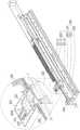
图1是依照本发明的一实施例的一种切换器系统的示意图。图2是图1的切换器系统的人机界面装置的示意图。请参考图1以及图2,本实施例的切换器系统1包括一切换器10以及一人机界面装置20,其中人机界面装置20及切换器10装设于一机柜30,机柜30具有多个机架32(图中示出四个)。FIG. 1 is a schematic diagram of a switch system according to an embodiment of the present invention. FIG. 2 is a schematic diagram of a human-machine interface device of the switch system of FIG. 1 . Please refer to FIG. 1 and FIG. 2 , the
具体而言,切换器10设置于机柜30的后方,人机界面装置20装设于切换器10的前方并电性连接切换器10。人机界面装置20可相对于切换器10朝机柜30外移动,以利使用者操作。在本实施例中,多台电脑主机(未图示)电性连接至切换器10,以使得使用者可通过切换器10的切换通过人机界面装置20选择性操控多台电脑主机。Specifically, the
于下详细说明本发明的人机界面装置20的结构及操作。要说明的是,虽然本发明的实施例以包含切换器10以及人机界面装置20的架构来说明,但本发明的人机界面装置20并不一定要搭配切换器10才可以实施,例如在另一实施例中,人机界面装置20本身亦可包含有具有运算处理的主机,而使得人机界面装置20可以单独使用,而不需要有切换器。此外,在本实施例中,切换器10例如是键盘、屏幕、鼠标切换器(Keyboard、Video、Mouse,KVMswitch),但在其他实施例中,切换器10也可为影音切换器,例如:矩阵式(matrix)影音切换器、网络切换器或者是影音分割器(video splitter)等,并不以此为限。The structure and operation of the human-
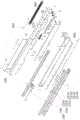
图3A是图2的滑动单元230与固定架220的爆炸示意图。图3B至图3E是图2的滑动单元230与固定架220于各种状态的剖视图。图3F至图3G是图1的人机界面装置20于各种状态的示意图。需注意的是,图3A至图3E仅从另一视角示出图2中人机界面装置20的其中一侧的滑动单元230,人机界面装置20的另一侧为对应的结构,因此不再赘述。此外,为清楚地示出滑动单元230内部构件,图3B至图3E为剖面示意图。FIG. 3A is an exploded schematic diagram of the sliding
请先参考图1以及图3A,本实施例的人机界面装置20包括一人机界面模块210、一固定架220以及一滑动单元230,其中滑动单元230耦接固定架220及人机界面模块210。Please refer to FIG. 1 and FIG. 3A first. The human-
在本实施例中,固定架220锁附于机架32,但在其他实施例中,固定架220固定于机架32的方式也可以为焊接、铆接或卡接等,并不以此为限。在本实施例中,固定架220是以第一固定架2201以及第二固定架2202两相配合的组件构成,但在其他实施例中,构成固定架220的组件数量也可以为一个或三个以上,只要固定架220能够与图1的机架32固定,皆属本发明欲保护的范围内。In this embodiment, the fixing
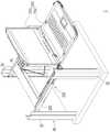
如图1所示,人机界面模块210具有可掀翻的一显示单元212以及一输入单元214。在本实施例中,因应使用者需求,显示单元212及输入单元214可分别或同时相对于切换器10朝机柜30外移动。此处,显示单元212为屏幕,输入单元214为键盘,但并不以此为限。要说明的是,本实施例的人机界面模块210可以单纯仅有显示单元212或者是显示单元212与输入单元214的结合。As shown in FIG. 1 , the man-
如图3A所示,本实施例的滑动单元230包括一滑轨组231,滑轨组231可滑动地连接至固定架220。具体来说,滑轨组231包括彼此可滑动地连接的一第一滑轨2311、一第二滑轨2312与第三滑轨2313。在本实施例中,第一滑轨2311包括了第一次滑轨2311X、第二次滑轨2311Y与第三次滑轨2311Z,第一次滑轨2311X可滑动地连接至固定架220,而第二次滑轨2311Y与第三次滑轨2311Z分别固定于第一次滑轨2311X上。第二滑轨2312与第三滑轨2313分别可滑动地连接至第一滑轨2311的第二次滑轨2311Y与第三次滑轨2311Z。第二滑轨2312与第三滑轨2313分别固接图2的显示单元212与输入单元214。也就是说,图2的人机界面模块210连接于滑轨组231而能够相对固定架220在图1所示的一收纳位置与图3G所示的一操作位置之间移动。As shown in FIG. 3A , the sliding
在本实施例中,人机界面装置20还包括一弹性件240以及一连动件250。本实施例的弹性件240的两端分别固定于滑轨组231与固定架220。具体来说,弹性件240的一端固定于连动件250,且连动件250会穿过固定架220而固定于第一滑轨2311。弹性件240的另一端则固定于第二固定架2202,而使弹性件240初始时为拉伸状态。在本实施例中,弹性件240为弹簧,但并不以此为限。In this embodiment, the human-
在本实施例中,滑动单元230还包括一切换件232,切换件232连接于滑轨组231,具体来说,切换件232固定于第二滑轨2312,用以在一干涉状态与一解锁状态之间切换。In this embodiment, the sliding
具体而言,当切换件232从图3B所示的位置移动至图3C所示位置时,切换件232干涉固定架220而处于干涉状态,并使显示单元212与输入单元214停留于图3F所示的一监控位置。Specifically, when the switching
当切换件232从图3C所示的位置到达图3D所示的位置时,切换件232与固定架220之间的干涉被解除而处于解锁状态。此时,弹性件240用以驱动滑轨组231而使显示单元212与输入单元214移动至图3G所示的操作位置。When the switching
如此一来,在本实施例的切换器系统1中,能够通过弹性件240驱动滑轨组231而达到自动掀翻显示单元212及调整显示单元212的倾斜角度的效果,进而增进使用者操控切换器系统1的便利性。In this way, in the
更详细来说,如图3A与图3B所示,在本实施例中,第一滑轨2311具有一第一开口C1与一第二开口C2。固定架220具有一凸块221、一弹性件222、一定位杆223以及一容置件224。在本实施例中,定位杆223卡合于凸块221的卡槽内,弹性件222套设于定位杆223。在本实施例中,凸块221、弹性件222、定位杆223配置于容置件224上。容置件224具有一抵靠面224A,抵靠面224A与定位杆223的延伸方向垂直,弹性件222两端分别抵靠于抵靠面224A以及凸块221。In more detail, as shown in FIG. 3A and FIG. 3B , in this embodiment, the first sliding
在本实施例中,弹性件222为弹簧,当弹性件222受压缩或拉伸时,由于弹性件222套设于定位杆223,定位杆223能够产生导引作用而使弹性件222具有较平稳的移动。在其他实施例中,弹性件222也可以由泡棉、橡胶或其他可压缩的材质而制成,或是固定架220也可以不包括定位杆223,并不以上述为限。In this embodiment, the
请参考图1与图3B,当使用者不使用切换器系统1时,显示单元212以及滑动单元230分别位于图1与图3B所示的收纳位置。此时,凸块221会因为弹性件222的弹性力驱动而伸入第一开口C1。本实施例通过凸块221伸入第一开口C1而限制第一滑轨2311的移动。Please refer to FIG. 1 and FIG. 3B , when the user does not use the
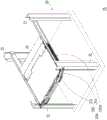
请参考图3C与图3F,当使用者欲使用切换器系统1时,使用者可以使显示单元212随第二滑轨2312从图1所示的收纳位置移动至图3F所示的监控位置,且使滑动单元230位于图3C所示的监控位置。此时,凸块221还位于第一开口C1,凸块221会干涉切换件232而使显示单元212停留于图3F所示的监控位置。Please refer to FIG. 3C and FIG. 3F, when the user wants to use the
请参考图3D、图3E与图3G,当使用者欲得到更好的操作视角时,使用者可以将显示单元212随第二滑轨2312从图3F所示的监控位置移动至图3G所示的操作位置。在移动显示单元212的过程中,切换件232会与显示单元212一同移动,且切换件232施加大于一预设值的力量于凸块221,使凸块221被切换件232推移而解除与第一开口C1的干涉。也就是说,凸块221会退出第一开口C1,滑动单元230的切换件232位于图3D所示的解锁位置。Please refer to FIG. 3D, FIG. 3E and FIG. 3G. When the user wants to obtain a better operating angle of view, the user can move the
当解除切换件232与凸块221之间的干涉时,弹性件240为了从初始的拉伸状态恢复成原本长度,会产生一拉力以驱动滑轨组231,进而使显示单元212自动地往图3G所示的操作位置移动。当显示单元212与滑动单元230位于图3G以及图3E所示的操作位置时,凸块221会受弹性件222的弹性力驱动伸入第二开口C2而限制第一滑轨2311继续移动。When the interference between the switching
在本实施例中,当显示单元212位于图3F所示的监控位置时,如图3C所示,凸块221是以一斜面F干涉切换件232。在本实施例中,斜面F倾斜于第二滑轨2312的移动方向,这样的设计方式能够使凸块221较不易因长久的使用而耗损,但并不以此为限。In this embodiment, when the
在本实施例中,显示单元212位于图3F所示的监控位置时,显示单元212与滑轨组231的移动方向的夹角为90度至95度,但当显示单元212位于图3G所示的操作位置时,显示单元212与滑轨组231的移动方向的夹角大于等于115度。换言之,本实施例的切换器系统1可有效地增加显示单元212的可翻掀角度。In this embodiment, when the
图3H是图2的滑动单元与固定架的示意图。请参考图3H,在本实施例中,切换器系统1还包括至少一固定件40,固定件40用以将图2的切换器10固定于固定架220,以避免随着显示单元212或输入单元214被拉动而导致与电脑主机之间的连线脱落。需注意的是,为清楚地示出出固定件40,图3H中的第一固定架2201以虚线示出。FIG. 3H is a schematic diagram of the sliding unit and the fixing frame in FIG. 2 . Please refer to FIG. 3H. In this embodiment, the
图3I是图2的滑动单元与固定架的局部放大剖视图。请参考图3I,在本实施例中,图2的人机界面装置20还包括至少一垫片260,配置于滑轨组231与固定架220之间,以使滑轨组231与固定架220之间能够较平稳地滑动并避免磨损。垫片260可为塑胶材质,如PET。FIG. 3I is a partially enlarged cross-sectional view of the sliding unit and the fixing frame in FIG. 2 . Please refer to FIG. 3I. In this embodiment, the human-
请参考图3A与图3I,具体来说,垫片260的上侧抵接第一滑轨2311的下表面,垫片260的下侧抵接第二固定架2202。在本实施例中,垫片260的数量为两个。在另一实施例中,垫片260的数量也可以为一个或一个以上。在其他实施例中,人机界面装置20也可以是利用多个滚珠,配置于滑轨组231与固定架220之间,以使滑轨组231与固定架220之间能够较平稳地滑动,并不以此为限制。Please refer to FIG. 3A and FIG. 3I , specifically, the upper side of the
以下将列举其他实施例以作为说明。在此必须说明的是,下述实施例沿用前述实施例的元件标号与部分内容,其中采用相同的标号来表示相同或近似的元件,并且省略了相同技术内容的说明。关于省略部分的说明可参考前述实施例,下述实施例不再重复赘述。Other embodiments are listed below for illustration. It must be noted here that the following embodiments use the component numbers and part of the content of the previous embodiments, wherein the same numbers are used to denote the same or similar components, and descriptions of the same technical content are omitted. For the description of omitted parts, reference may be made to the foregoing embodiments, and the following embodiments will not be repeated.
图4是依照本发明的另一实施例的一种切换器系统的示意图。图5是图4的切换器系统的人机界面装置20A的示意图。图6A是图5的滑动单元230A与固定架220A的爆炸示意图。图6B与图6C为图6A的滑动单元230A与固定架220A于各种状态的示意图。图6D与图6E为图4的人机界面装置20A于各种状态的示意图。需注意的是,图6A与图6B仅示出人机界面装置20A其中一侧的滑动单元与固定架的结构,人机界面装置20A的另一侧为对应的结构,因此不再赘述。FIG. 4 is a schematic diagram of a switch system according to another embodiment of the present invention. FIG. 5 is a schematic diagram of the human-
请参考图4,在本实施例中,切换器系统1A的人机界面装置20A与图2的切换器系统1的人机界面装置20略有不同,差异在于滑动机制的设计。Please refer to FIG. 4 , in this embodiment, the human-
于下详细说明本发明的人机界面装置20A的结构及操作。请先参考图6A,在本实施例中,滑动单元230A包括一滑轨组231A,其中滑轨组231A可滑动地连接至固定架220A。详细来说,滑轨组231A包括彼此可滑动地连接的一第一滑轨2311A、一第二滑轨2312A与一第三滑轨2313A。第一滑轨2311A可滑动地连接固定架220A。第二滑轨2312A与第三滑轨2313A分别可滑动地连接至第一滑轨2311A,且第二滑轨2312A与第三滑轨2313A分别固接图5的显示单元212与输入单元214。The structure and operation of the human-
在本实施例中,构成固定架220A的组件的数量为两个,但在其他实施例中,构成固定架220A的组件的数量也可以为一个或三个以上,只要固定架220A能够与机架32固定,皆属本发明欲保护的范围。In this embodiment, the number of components constituting the fixed
在本实施例中,滑动单元230A还包括一切换件232A,切换件232A连接于滑轨组231A。具体来说,切换件232A枢接于第一滑轨2311A,切换件232A经由枢接部T枢接于第一滑轨2311A而位于第一滑轨2311A与固定架220A之间,且切换件232A能够以枢接部T为中心而转动,用以在一干涉状态与一解锁状态之间切换。In this embodiment, the sliding
在本实施例中,人机界面装置20A还包括一弹性件240A,弹性件240A两端分别固定于滑轨组231A与固定架220A。弹性件240A能够驱动滑轨组231A而使图4的显示单元212移动至图6E所示的操作位置。在本实施例中,弹性件240A为弹簧,但并不以此为限。In this embodiment, the man-
进一步来说,请参照图6B,本实施例的固定架220A具有一凸块221A,其中凸块221A用以干涉切换件232A而使滑动单元230A在图4所示的收纳位置或图6D所示的监控位置之间移动。具体来说,切换件232A具有凸出的卡合部D,凸块221A能够卡抵于卡合部D,且使弹性件240A处于拉伸状态。Further, referring to FIG. 6B , the fixing
在本实施例中,固定架220A具有一第一穿孔H1以及一第二穿孔H2。第一滑轨2311A包括了第一次滑轨2311A1、第二次滑轨2311A2、第三次滑轨2311A3与第四次滑轨2311A4,第一次滑轨2311A1可滑动地连接至固定架220A,第二次滑轨2311A2固定于第一次滑轨2311A1上,而第三次滑轨2311A3与第四次滑轨2311A4分别固定于第二次滑轨2311A2上。第二滑轨2312A与第三滑轨2313A分别可滑动地连接至第三次滑轨2311A3与第四次滑轨2311A4。第二滑轨2312A与第三滑轨2313A分别固接图5的显示单元212与输入单元214。第一次滑轨2311A1通过两个导引件G而可滑动地耦接于第一穿孔H1以及第二穿孔H2内。In this embodiment, the fixing
在本实施例中,人机界面装置20A还包括至少一垫片260A,以使滑轨组231A与固定架220A之间能够较平稳地滑动并避免磨损。In this embodiment, the man-
请参考图4与图6B,当使用者不使用切换器系统1A时,显示单元212以及滑动单元230A位于图4与图6B所示的收纳位置,此时,凸块221A干涉切换件232A的卡合部D。Please refer to FIG. 4 and FIG. 6B. When the user does not use the
当使用者欲使用切换器系统1时,使用者可以使显示单元212随第二滑轨2312A从图4所示的收纳位置移动至图6D所示的监控位置。此时,第一次滑轨2311A1尚未相对固定架220A滑动,凸块221A还干涉切换件232A的卡合部D,而使显示单元212停留于图6D所示的监控位置。When the user wants to use the
请参考图6C与图6E,当使用者欲得到更好的操作视角时,使用者可以相对于第一滑轨2311A来按压切换件232A露出在外面的一按压侧L,使切换件232A以枢接部T为中心而相对于第一滑轨2311A旋转,且使显示单元212随第二滑轨2312A从图6D所示的监控位置移动至图6E所示的操作位置。具体来说,当使用者解除卡合部D与切换件232A之间的干涉时,切换件232A处于解锁状态。并且,由于弹性件240A初始为拉伸状态,故弹性件240A为恢复原本长度会产生一拉力以驱动滑轨组231A,而使显示单元212受拉力而自动地往图6E所示的操作位置移动。Please refer to FIG. 6C and FIG. 6E , when the user wants to obtain a better operating angle, the user can press the exposed pressing side L of the switching
此外,在本实施例中,人机界面装置20A还包括一弹簧S,弹簧S的一端固定于第一滑轨2311A的一第一固定部P1,弹簧S的另一端固定于切换件232A的按压侧L的一第二固定部P2,用以保持切换件232A相对于第一滑轨2311A的姿态。也就是说,当切换件232A被推移产生转动时,切换件232A可通过弹簧S回复至初始位置。In addition, in this embodiment, the man-
综上所述,在本发明的人机界面装置与切换器系统中,弹性件的两端分别固定于滑轨组与固定架。当切换件处于干涉状态时,切换件干涉固定架而使显示单元停留于一监控位置。当切换件处于解锁状态时,切换件解除与固定架的干涉而使显示单元可以离开监控位置。当切换件处于解锁状态时,弹性件驱动滑轨组而使显示单元移动至操作位置,进而达到自动掀翻显示单元的目的。To sum up, in the man-machine interface device and the switch system of the present invention, the two ends of the elastic member are respectively fixed to the slide rail set and the fixing frame. When the switching element is in the interference state, the switching element interferes with the fixing frame so that the display unit stays at a monitoring position. When the switching member is in the unlocked state, the switching member removes the interference with the fixing frame so that the display unit can leave the monitoring position. When the switching member is in the unlocked state, the elastic member drives the sliding rail group to move the display unit to the operating position, thereby achieving the purpose of automatically turning over the display unit.
虽然本发明已以实施例揭示如上,然其并非用以限定本发明,任何所属技术领域中的技术人员,在不脱离本发明的精神和范围内,当可作些许的更改与润饰,故本发明的保护范围当视权利要求所界定的为准。Although the present invention has been disclosed above with the embodiments, it is not intended to limit the present invention. Any person skilled in the art can make some changes and modifications without departing from the spirit and scope of the present invention. Therefore, this The scope of protection of the invention should be defined by the claims.
Claims (14)
Applications Claiming Priority (2)
| Application Number | Priority Date | Filing Date | Title |
|---|---|---|---|
| TW108126747 | 2019-07-29 | ||
| TW108126747ATWI704855B (en) | 2019-07-29 | 2019-07-29 | Human-computer interface device and switch system |
Publications (2)
| Publication Number | Publication Date |
|---|---|
| CN112306150A CN112306150A (en) | 2021-02-02 |
| CN112306150Btrue CN112306150B (en) | 2023-02-28 |
Family
ID=73644002
Family Applications (1)
| Application Number | Title | Priority Date | Filing Date |
|---|---|---|---|
| CN201911147689.XAActiveCN112306150B (en) | 2019-07-29 | 2019-11-21 | Man-machine interface device and switcher system |
Country Status (2)
| Country | Link |
|---|---|
| CN (1) | CN112306150B (en) |
| TW (1) | TWI704855B (en) |
Families Citing this family (1)
| Publication number | Priority date | Publication date | Assignee | Title |
|---|---|---|---|---|
| TWI775585B (en)* | 2021-08-30 | 2022-08-21 | 宏正自動科技股份有限公司 | Electrical device |
Citations (7)
| Publication number | Priority date | Publication date | Assignee | Title |
|---|---|---|---|---|
| JP2000074023A (en)* | 1998-08-27 | 2000-03-07 | Kokuyo Co Ltd | Telescopic device |
| JP2009104398A (en)* | 2007-10-23 | 2009-05-14 | Fujitsu Component Ltd | Console drawer |
| CN201260285Y (en)* | 2008-08-20 | 2009-06-17 | 锋厚科技股份有限公司 | Rack construction with locate function |
| CN204087078U (en)* | 2013-03-13 | 2015-01-07 | 以乔纳森工程方案名义经营的乔纳森制造公司 | Slide assemblies |
| TW201515554A (en)* | 2013-10-11 | 2015-04-16 | King Slide Works Co Ltd | Slide rail assembly |
| CN105094955A (en)* | 2014-05-20 | 2015-11-25 | 宏正自动科技股份有限公司 | Human interface device and switcher system using same |
| TWM519382U (en)* | 2015-10-14 | 2016-03-21 | Nueteq Technology Inc | Rack structure with strengthened shaft supporting function |
Family Cites Families (2)
| Publication number | Priority date | Publication date | Assignee | Title |
|---|---|---|---|---|
| TWI273372B (en)* | 2005-04-18 | 2007-02-11 | Aten Int Co Ltd | Sliding flat panel display and keyboard module |
| TWI288595B (en)* | 2005-06-24 | 2007-10-11 | Aten Int Co Ltd | Sliding module positioning device |
- 2019
- 2019-07-29TWTW108126747Apatent/TWI704855B/enactive
- 2019-11-21CNCN201911147689.XApatent/CN112306150B/enactiveActive
Patent Citations (7)
| Publication number | Priority date | Publication date | Assignee | Title |
|---|---|---|---|---|
| JP2000074023A (en)* | 1998-08-27 | 2000-03-07 | Kokuyo Co Ltd | Telescopic device |
| JP2009104398A (en)* | 2007-10-23 | 2009-05-14 | Fujitsu Component Ltd | Console drawer |
| CN201260285Y (en)* | 2008-08-20 | 2009-06-17 | 锋厚科技股份有限公司 | Rack construction with locate function |
| CN204087078U (en)* | 2013-03-13 | 2015-01-07 | 以乔纳森工程方案名义经营的乔纳森制造公司 | Slide assemblies |
| TW201515554A (en)* | 2013-10-11 | 2015-04-16 | King Slide Works Co Ltd | Slide rail assembly |
| CN105094955A (en)* | 2014-05-20 | 2015-11-25 | 宏正自动科技股份有限公司 | Human interface device and switcher system using same |
| TWM519382U (en)* | 2015-10-14 | 2016-03-21 | Nueteq Technology Inc | Rack structure with strengthened shaft supporting function |
Also Published As
| Publication number | Publication date |
|---|---|
| TW202106142A (en) | 2021-02-01 |
| CN112306150A (en) | 2021-02-02 |
| TWI704855B (en) | 2020-09-11 |
Similar Documents
| Publication | Publication Date | Title |
|---|---|---|
| JP6339660B2 (en) | Hinge mechanism for mounting rotatable parts | |
| US7599178B2 (en) | Connection assembly for connecting bodies, and portable electronic apparatus and base using the same | |
| US7936558B2 (en) | Electronic device | |
| US9261910B2 (en) | Fixing device for fixing a portable electronic device and portable electronic system therewith | |
| US9658655B2 (en) | Electronic apparatus and cover structure thereof | |
| US20080284300A1 (en) | Kvm switching device, sever rack assembly and sliding mechanism thereof | |
| KR20140138680A (en) | Device kickstand | |
| TWI487458B (en) | Interface card module and electronic device having the same | |
| TW201408171A (en) | Portable computer | |
| US8976522B2 (en) | Portable electronic device and docking device thereof | |
| US9158341B2 (en) | Portable computer | |
| US9060445B2 (en) | Electronic apparatus having a display panel | |
| TW202111471A (en) | Mount for add-in card, electronic device, and carrier | |
| CN103118513B (en) | electronic device | |
| CN112306150B (en) | Man-machine interface device and switcher system | |
| CN103262508A (en) | portable electronic device | |
| CN108459740B (en) | Switching assembly | |
| US20130279028A1 (en) | Sliding mechanism and electronic device using the same | |
| CN115248635A (en) | input device | |
| CN103425196A (en) | Electronic device | |
| CN110825178B (en) | Computer cabinet with movable base | |
| TWI724903B (en) | Notebook computer with touch control function | |
| CN211702758U (en) | Extraction device and system thereof | |
| CN110825177B (en) | Computer cabinet with telescopic caster | |
| CN103517605A (en) | Guiding mechanism and portable electronic device thereof |
Legal Events
| Date | Code | Title | Description |
|---|---|---|---|
| PB01 | Publication | ||
| PB01 | Publication | ||
| SE01 | Entry into force of request for substantive examination | ||
| SE01 | Entry into force of request for substantive examination | ||
| GR01 | Patent grant | ||
| GR01 | Patent grant |