CN112304218B - Tool center point position calibration method and system of industrial robot - Google Patents
Tool center point position calibration method and system of industrial robotDownload PDFInfo
- Publication number
- CN112304218B CN112304218BCN202011139819.8ACN202011139819ACN112304218BCN 112304218 BCN112304218 BCN 112304218BCN 202011139819 ACN202011139819 ACN 202011139819ACN 112304218 BCN112304218 BCN 112304218B
- Authority
- CN
- China
- Prior art keywords
- plane
- center
- flange
- coordinates
- coordinate system
- Prior art date
- Legal status (The legal status is an assumption and is not a legal conclusion. Google has not performed a legal analysis and makes no representation as to the accuracy of the status listed.)
- Active
Links
- 238000000034methodMethods0.000titleclaimsabstractdescription58
- 239000013598vectorSubstances0.000claimsdescription26
- 230000015654memoryEffects0.000claimsdescription19
- 238000004364calculation methodMethods0.000claimsdescription15
- 239000011159matrix materialSubstances0.000claimsdescription11
- 230000009466transformationEffects0.000claimsdescription11
- 238000004590computer programMethods0.000claimsdescription7
- 238000005259measurementMethods0.000claimsdescription5
- 230000001131transforming effectEffects0.000claims1
- 230000008569processEffects0.000abstractdescription8
- 238000012545processingMethods0.000description5
- 238000010586diagramMethods0.000description2
- 238000012986modificationMethods0.000description2
- 230000004048modificationEffects0.000description2
- 230000003287optical effectEffects0.000description2
- OKTJSMMVPCPJKN-UHFFFAOYSA-NCarbonChemical compound[C]OKTJSMMVPCPJKN-UHFFFAOYSA-N0.000description1
- 230000009286beneficial effectEffects0.000description1
- 238000000354decomposition reactionMethods0.000description1
- 238000013461designMethods0.000description1
- 230000006870functionEffects0.000description1
- 229910021389grapheneInorganic materials0.000description1
- 238000000691measurement methodMethods0.000description1
- 230000002085persistent effectEffects0.000description1
Images


Classifications
- G—PHYSICS
- G01—MEASURING; TESTING
- G01B—MEASURING LENGTH, THICKNESS OR SIMILAR LINEAR DIMENSIONS; MEASURING ANGLES; MEASURING AREAS; MEASURING IRREGULARITIES OF SURFACES OR CONTOURS
- G01B11/00—Measuring arrangements characterised by the use of optical techniques
- G01B11/002—Measuring arrangements characterised by the use of optical techniques for measuring two or more coordinates
- G01B11/005—Measuring arrangements characterised by the use of optical techniques for measuring two or more coordinates coordinate measuring machines
- G—PHYSICS
- G01—MEASURING; TESTING
- G01B—MEASURING LENGTH, THICKNESS OR SIMILAR LINEAR DIMENSIONS; MEASURING ANGLES; MEASURING AREAS; MEASURING IRREGULARITIES OF SURFACES OR CONTOURS
- G01B21/00—Measuring arrangements or details thereof, where the measuring technique is not covered by the other groups of this subclass, unspecified or not relevant
- G01B21/02—Measuring arrangements or details thereof, where the measuring technique is not covered by the other groups of this subclass, unspecified or not relevant for measuring length, width, or thickness
- G01B21/04—Measuring arrangements or details thereof, where the measuring technique is not covered by the other groups of this subclass, unspecified or not relevant for measuring length, width, or thickness by measuring coordinates of points
- G01B21/042—Calibration or calibration artifacts
- Y—GENERAL TAGGING OF NEW TECHNOLOGICAL DEVELOPMENTS; GENERAL TAGGING OF CROSS-SECTIONAL TECHNOLOGIES SPANNING OVER SEVERAL SECTIONS OF THE IPC; TECHNICAL SUBJECTS COVERED BY FORMER USPC CROSS-REFERENCE ART COLLECTIONS [XRACs] AND DIGESTS
- Y02—TECHNOLOGIES OR APPLICATIONS FOR MITIGATION OR ADAPTATION AGAINST CLIMATE CHANGE
- Y02P—CLIMATE CHANGE MITIGATION TECHNOLOGIES IN THE PRODUCTION OR PROCESSING OF GOODS
- Y02P90/00—Enabling technologies with a potential contribution to greenhouse gas [GHG] emissions mitigation
- Y02P90/02—Total factory control, e.g. smart factories, flexible manufacturing systems [FMS] or integrated manufacturing systems [IMS]
Landscapes
- Physics & Mathematics (AREA)
- General Physics & Mathematics (AREA)
- Manipulator (AREA)
- Numerical Control (AREA)
Abstract
Description
Translated fromChinese技术领域technical field
本发明属于工业机器人标定技术领域,具体涉及工业机器人的工具中心点位置标定方法及系统。The invention belongs to the technical field of industrial robot calibration, and in particular relates to a method and system for calibrating the position of a tool center point of an industrial robot.
背景技术Background technique
工业机器人具有高精度、稳定性好,效率高等特点而被广泛应用于各个领域,但是由于汽车装配等领域对机器人的精度要求非常高,工业机器人在进行不同的任务作业时,要在机器人法兰末端安装不同的工具,需要根据不同的工具建立不同的工具坐标系,工具坐标系的原点定义为工具中心点(TCP),工业机器人要进行精确的任务作业时,需要确定TCP的位置,即TCP在法兰末端坐标系下的位置。Industrial robots have the characteristics of high precision, good stability and high efficiency and are widely used in various fields. However, due to the high precision requirements of robots in automotive assembly and other fields, industrial robots must be installed on the robot flange when performing different tasks. Different tools are installed at the end, and different tool coordinate systems need to be established according to different tools. The origin of the tool coordinate system is defined as the tool center point (TCP). When the industrial robot needs to perform precise tasks, the position of the TCP needs to be determined, that is, the TCP The position in the flange end coordinate system.
目前,工业机器人的TCP标定方法主要有以下两种:At present, there are two main methods of TCP calibration for industrial robots:
第一种方法是不借助外界设备,基于机器人本体进行TCP位置标定,存在的问题是TCP标定精度不高,无法满足部分高精度作业任务。如作者牛雪娟等人在期刊《自动化与仪表》上发明的名称为《基于奇异值分解的机器人工具坐标标定》的论文中,通过三点五步法实现了工具坐标系标定,但标定精度无法保证。The first method is to calibrate the TCP position based on the robot body without the aid of external equipment. The problem is that the accuracy of the TCP calibration is not high and cannot meet some high-precision tasks. For example, in the paper titled "Robot Tool Coordinate Calibration Based on Singular Value Decomposition" invented by the author Niu Xuejuan and others in the journal "Automation and Instrumentation", the tool coordinate system calibration was realized by the three-point-five-step method, but the calibration accuracy cannot be guaranteed. .
第二种方法是基于外界测量设备(如激光跟踪仪)进行TCP位置标定,例如作者向民志等人在期刊《航空制造技术》上发表的名称为《激光跟踪仪与机器人坐标系转换方法研究》的论文中指出,利用距离约束原则,即空间中两点在基坐标系下和跟踪仪坐标系下的距离不变的关系,求解TCP在法兰末端坐标系下的坐标。该方法的缺点是,由于需要控制机器人运动多个位置,标定过程中很容易引起位置误差,降低了标定精度。The second method is to calibrate the TCP position based on external measuring equipment (such as laser tracker). "The paper pointed out that using the principle of distance constraint, that is, the relationship between the distance between two points in the space under the base coordinate system and the tracker coordinate system, the coordinates of the TCP under the flange end coordinate system are solved. The disadvantage of this method is that, due to the need to control the robot to move to multiple positions, it is easy to cause position errors during the calibration process, which reduces the calibration accuracy.
发明内容SUMMARY OF THE INVENTION
本发明的目的是提供一种工业机器人的工具中心点位置标定方法,用于解决现有标定方法精度低的问题;同时,本发明提出一种工业机器人的工具中心点位置标定系统,以解决现有标定方法精度低的问题。The purpose of the present invention is to provide a method for calibrating the position of the tool center point of an industrial robot, which is used to solve the problem of low precision of the existing calibration method; There is a problem of low accuracy of the calibration method.
基于上述目的,一种工业机器人的工具中心点位置标定方法的技术方案如下:Based on the above purpose, the technical solution of a method for calibrating the tool center point position of an industrial robot is as follows:
1)测量机器人末端法兰的三个孔位置处靶球的球心坐标,三个孔位置处靶球的球心位于同一个圆上,根据测得靶球的球心坐标确定出第一平面方程,结合靶球球心与圆心之间的圆心方程,计算出圆心的坐标;根据所述第一平面方程和所述圆心的坐标,计算经过所述圆心且垂直与第一平面的法线方程,从而确定出法兰坐标系的Z轴方向向量;1) Measure the coordinates of the center of the target ball at the three hole positions of the flange at the end of the robot, the center of the target ball at the three hole positions is located on the same circle, and determine the first plane according to the measured coordinates of the center of the target ball Equation, combined with the center equation between the center of the target ball and the center of the circle, calculate the coordinates of the center of the circle; according to the first plane equation and the coordinates of the center of the circle, calculate the normal equation that passes through the center of the circle and is perpendicular to the first plane , so as to determine the Z-axis direction vector of the flange coordinate system;
2)测量机器人末端法兰盘平面上靶球的球心坐标,定义过球心且平行于第一平面的平面为第二平面,结合第一平面和第二平面的平行关系,计算第二平面方程,进而计算出第一平面与第二平面之间的距离;根据该距离以及第二平面与法兰盘平面间的距离,求出第一平面α2与法兰盘平面α1之间的距离,根据该距离结合所述第一平面的法线方程,计算法兰坐标系的原点坐标;2) Measure the sphere center coordinates of the target ball on the flange plane at the end of the robot, define the plane passing through the sphere center and parallel to the first plane as the second plane, and calculate the second plane based on the parallel relationship between the first plane and the second plane equation, and then calculate the distance between the first plane and the second plane; according to the distance and the distance between the second plane and the flange plane, find the distance between the first plane α2 and the flange plane α1 distance, according to the distance combined with the normal equation of the first plane, calculate the origin coordinates of the flange coordinate system;
3)测量法兰盘平面上位置L处放置的靶球的球心坐标,所述法兰盘的中心到位置L处的方向为法兰坐标系的X轴方向,由于步骤1中所求的圆心坐标到L处靶球球心坐标的方向与X轴方向平行,因此根据位置L处靶球的球心坐标和所述圆心的坐标(这里涉及到“步骤1)中所求的圆心坐标到L处靶球球心坐标的方向”与法兰盘中心到位置L的方向平行,因此X轴正方向的求解变成了圆心坐标到L处靶球球心坐标的方向),计算出法兰坐标系的X轴方向向量,并结合Z轴方向向量,求出法兰坐标系的Y轴方向向量;3) Measure the spherical center coordinates of the target ball placed at the position L on the flange plane, and the direction from the center of the flange to the position L is the X-axis direction of the flange coordinate system. The direction from the coordinates of the center of the circle to the coordinates of the center of the target ball at L is parallel to the X-axis direction, so according to the coordinates of the center of the target ball at position L and the coordinates of the center of the circle (this involves the coordinates of the center of the circle obtained in "Step 1) to The direction of the center coordinate of the target ball at L" is parallel to the direction from the center of the flange to the position L, so the solution of the positive direction of the X-axis becomes the direction from the center coordinate to the center coordinate of the target ball at L), calculate the flange The X-axis direction vector of the coordinate system, and combined with the Z-axis direction vector, the Y-axis direction vector of the flange coordinate system is obtained;
4)根据法兰坐标系的原点坐标以及X轴、Y轴、Z轴方向向量,计算得到法兰坐标系与测量仪器坐标系的位姿变换矩阵;4) Calculate the pose transformation matrix of the flange coordinate system and the measuring instrument coordinate system according to the origin coordinates of the flange coordinate system and the direction vectors of the X-axis, Y-axis and Z-axis;
5)法兰末端安装工具后测量固定在工具上的靶球球心坐标,利用所述位姿变换矩阵,将该球心坐标变换至法兰坐标系下,得到工具中心点在法兰坐标系下的坐标。5) After installing the tool at the end of the flange, measure the coordinates of the center of the target ball fixed on the tool, and use the pose transformation matrix to transform the coordinates of the center of the sphere into the flange coordinate system to obtain the tool center point in the flange coordinate system. the coordinates below.
一种工业机器人的工具中心点位置标定系统的技术方案如下:A technical scheme of a tool center point position calibration system for an industrial robot is as follows:
包括坐标测量仪器、存储器和处理器,以及存储在所述存储器上并在所述处理器上运行的计算机程序,所述处理器采集连接所述坐标测量仪器,所述坐标测量仪器用于按照上述的方法测量各靶球的球心坐标,并将各靶球的球心坐标测量信息发送给处理器,所述处理器与所述存储器相耦合,所述处理器在执行所述计算机程序时按照上述的方法实现工具中心点的位置标定计算。It includes a coordinate measuring instrument, a memory and a processor, and a computer program stored on the memory and running on the processor, the processor collecting and connecting the coordinate measuring instrument, and the coordinate measuring instrument is used for the above-mentioned The method measures the spherical center coordinates of each target ball, and sends the spherical center coordinate measurement information of each target ball to the processor, the processor is coupled with the memory, and the processor executes the computer program according to The above method realizes the position calibration calculation of the tool center point.
上述两个技术方案的有益效果是:The beneficial effects of the above two technical solutions are:
本发明的标定方法通过五个点测量得到标定法兰末端坐标系在激光跟踪仪下的位姿变换矩阵,之后无论给机器人安装何种工具,都只需要利用跟踪仪测得一个点,即固定在工具上的靶球位置,就能解算TCP位置,即只需要测量六个点即可实现TCP位置标定,有效提高了标定的效率。由于本发明的方法不需要控制机器人运动,只需要利用激光跟踪仪测得法兰盘上的多个位置,就能完成TCP的位置标定,大大简化了标定过程;并且,由于无需机器人运动,也避免了机器人的位置误差引入标定过程,提高了标定精度。The calibration method of the present invention obtains the pose transformation matrix of the coordinate system of the end of the calibration flange under the laser tracker by measuring five points, and then no matter what kind of tool is installed on the robot, only one point needs to be measured by the tracker, that is, the fixed point At the target ball position on the tool, the TCP position can be calculated, that is, only six points need to be measured to realize the TCP position calibration, which effectively improves the calibration efficiency. Because the method of the present invention does not need to control the movement of the robot, and only needs to use the laser tracker to measure multiple positions on the flange, the position calibration of the TCP can be completed, which greatly simplifies the calibration process; The position error of the robot is introduced into the calibration process, and the calibration accuracy is improved.
进一步的,所述第一平面方程如下:Further, the first plane equation is as follows:
Ax+By+Cz+d1=0Ax+By+Cz+d1 =0
式中,A、B、C、d1均为第一平面方程的参数。In the formula, A, B, C, and d1 are all parameters of the first plane equation.
进一步的,所述圆心方程如下:Further, the center equation is as follows:

式中,(x1,y1,z1),(x2,y2,z2),(x3,y3,z3)为三个孔位置处靶球的球心坐标,R为靶球球心到圆心的距离,(x,y,z)为待求的圆心坐标。In the formula, (x1 , y1 , z1 ), (x2 , y2 , z2 ), (x3 , y3 , z3 ) are the coordinates of the center of the target ball at the three hole positions, and R is The distance from the center of the target ball to the center of the circle, (x, y, z) is the coordinates of the center of the circle to be found.
进一步的,所述第一平面的法线方程如下:Further, the normal equation of the first plane is as follows:

式中,(x4,y4,z4)为步骤1)计算出的圆心的坐标。In the formula, (x4 , y4 , z4 ) are the coordinates of the center of the circle calculated in step 1).
进一步的,根据法兰盘上放置的靶球球心坐标,结合第一平面和第二平面的平行关系,所述第二平面的平面方程以及第一平面与第二平面间的距离计算式如下:Further, according to the coordinates of the center of the target ball placed on the flange, in combination with the parallel relationship between the first plane and the second plane, the plane equation of the second plane and the calculation formula of the distance between the first plane and the second plane are as follows: :
α3:Ax+By+Cz+d2=0α3 : Ax+By+Cz+d2 =0
d=|d1-d2|d=|d1 -d2 |
式中,A、B、C、d2均为第二平面方程的参数;d为第一平面与第二平面之间的距离。In the formula, A, B, C, and d2 are all parameters of the second plane equation; d is the distance between the first plane and the second plane.
进一步的,所述第一平面与法兰盘平面之间的距离计算式如下:Further, the calculation formula of the distance between the first plane and the flange plane is as follows:
s=r-ds=r-d
式中,s为第一平面与法兰盘平面之间的距离,r为第二平面与法兰盘平面之间的距离(即靶球的半径),d为第一平面与第二平面之间的距离。In the formula, s is the distance between the first plane and the flange plane, r is the distance between the second plane and the flange plane (that is, the radius of the target ball), and d is the distance between the first plane and the second plane. distance between.
进一步的,所述法兰坐标系的原点坐标为
附图说明Description of drawings
图1是本发明方法实施例中的工具中心点位置标定方法流程图;Fig. 1 is the flow chart of the method for calibrating the position of the tool center point in the method embodiment of the present invention;
图2是本发明方法实施例中的工业机器人的法兰盘平面图;Fig. 2 is the flange plan view of the industrial robot in the method embodiment of the present invention;
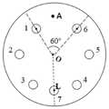
图3是本发明方法实施例中在机器人末端法兰盘平面上A位置处固定靶球的位置示意图;3 is a schematic view of the position of the fixed target ball at the position A on the plane of the robot end flange in the embodiment of the method of the present invention;
图4是本发明方法实施例中的第一平面、第二平面和法兰盘平面之间的位置关系图;4 is a positional relationship diagram between the first plane, the second plane and the flange plane in the method embodiment of the present invention;
图5是本发明系统实施例中的标定系统示意图。FIG. 5 is a schematic diagram of a calibration system in a system embodiment of the present invention.
具体实施方式Detailed ways
下面结合附图对本发明的具体实施方式作进一步的说明。The specific embodiments of the present invention will be further described below with reference to the accompanying drawings.
方法实施例:Method example:
本实施例提出一种工业机器人的工具中心点位置标定方法,利用激光跟踪仪进行六点测量,进而标定出TCP在法兰坐标系下的坐标,其实现思路为:如图1所示,首先,根据法兰盘的结构设计,通过法兰上三个孔处的靶球坐标确定出的第一平面方程,结合靶球坐标确定的圆心O1的坐标,利用轴线测量法得到经过圆心O1且垂直于第一平面α2的法线l1的方程,从而确定出法兰坐标系的Z轴方向向量;This embodiment proposes a method for calibrating the position of the tool center point of an industrial robot. The laser tracker is used to measure six points, and then the coordinates of the TCP in the flange coordinate system are calibrated. The realization idea is as follows: as shown in Figure 1, firstly , according to the structural design of the flange, the first plane equation determined by the coordinates of the target ball at the three holes on the flange, combined with the coordinates of the center O1 determined by the coordinates of the target ball, the axis measurement method is used to obtain the center O1 and is perpendicular to the equation of the normall1 of the first planeα2 , so as to determine the Z-axis direction vector of the flange coordinate system;
然后,通过测量法兰盘平面上的靶球坐标,结合第一平面和第二平面的平行关系,确定第二平面方程,之后计算第二平面α3与第一平面α2之间的距离,进而求出第一平面α2与法兰盘平面α1之间的距离s,结合求得的圆心O1的坐标,通过空间几何的方法解算出法兰坐标系的原点O坐标;然后,根据圆心O1的坐标和位置L处靶球的位置关系,得到法兰坐标系的X轴方向向量,结合Z轴方向向量求出Y轴方向向量;Then, by measuring the coordinates of the target ball on the plane of the flange, combining the parallel relationship between the first plane and the second plane, the equation of the second plane is determined, and then the distance between thesecond planeα3 and the first plane α2 is calculated, Then, the distance s between the first plane α2 and the flange plane α1 is obtained, combined with the obtained coordinates of the center O1 , the origin O coordinate of the flange coordinate system is solved by the method of space geometry; then, according to The coordinate of the circle center O1 and the positional relationship of the target ball at the position L, the X-axis direction vector of the flange coordinate system is obtained, and the Y-axis direction vector is obtained in combination with the Z-axis direction vector;
最后,根据上面求得的X轴、Y轴、Z轴方向向量,以及法兰坐标系的原点坐标,通过计算得到法兰坐标系与跟踪仪坐标系的位姿变换矩阵,只需要再测一个点,即固定在工具上的靶球位置,就可以通过该变换矩阵,计算得到TCP在法兰坐标系下的位置。Finally, according to the X-axis, Y-axis, Z-axis direction vectors obtained above, and the origin coordinates of the flange coordinate system, the pose transformation matrix of the flange coordinate system and the tracker coordinate system is obtained by calculation, and only one more measurement is needed. Point, that is, the position of the target ball fixed on the tool, the position of the TCP in the flange coordinate system can be calculated through the transformation matrix.
下面以工业机器人ABB IRB 2600为例,介绍本发明工具中心点位置标定方法的具体实现过程:The following takes the industrial robot ABB IRB 2600 as an example to introduce the specific implementation process of the tool center point position calibration method of the present invention:
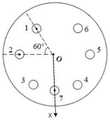
机器人的法兰盘平面如图2所示,小孔1,2…6均匀分布,相邻两孔间的夹角为60°,法兰盘圆心O到小孔7(即位置L处)的圆心方向为法兰坐标系的X轴正方向,定义法兰盘所在的平面为α1。The flange plane of the robot is shown in Figure 2. The
步骤一,将靶球依次放在机器人末端法兰的三个孔1、3、5的位置处,使靶球的球心位于同一个圆上,圆心为O1,靶球的球心依次为Oo1、Oo2、Oo3,球心所在的平面为α2。然后,利用激光跟踪仪分别测量靶球的球心坐标,三个球心坐标依次为(x1,y1,z1),(x2,y2,z2),(x3,y3,z3)。
根据测得的靶球球心坐标Oo1、Oo2、Oo3,计算得到球心Oo1、Oo2、Oo3所在的平面方程α2和圆心O1的位置,计算式如下:According to the measured coordinates of the target ball center Oo1 , Oo2 , Oo3 , the position of the plane equation α2 and the circle center O1 where the spherical centers Oo1 , Oo2 , and Oo3 are located, and the calculation formula is as follows:
α2:
O1:
整理得到,平面α2的一般方程为After finishing, the general equation of plane α2 is
α2:Ax+By+Cz+d1=0 (3)α2 : Ax+By+Cz+d1 =0 (3)
根据上面确定的第一平面方程,结合圆心O1的坐标(x4,y4,z4),计算出经过圆心O1且垂直于第一平面α2的法线l1的方程,计算式如下:According to the first plane equation determined above, combined with the coordinates (x4 , y4 , z4 ) of the center O1 , the equation of the normal l1 passing through the center O1 and perpendicular to the first plane α2 is calculated, and the formula is as follows:
l1:
根据该法线方程确定法兰坐标系的Z轴单位方向向量,即Z轴单位方向向量即为法线l1的单位方向向量,计算式如下:According to the normal equation, the unit direction vector of the Z-axis of the flange coordinate system is determined, that is, the unit direction vector of the Z-axis is the unit direction vector of the normal linel1 . The calculation formula is as follows:

步骤二,将靶球放在法兰盘平面任意位置处(如图3中A位置处),跟踪仪测得靶球球心坐标为Oo4,设过Oo4且平行于平面α2的平面为第二平面α3。根据第一平面方程和Oo4的位置,确定出第二平面方程α3,计算式如下:
α3:Ax+By+Cz+d2=0 (6)α3 : Ax+By+Cz+d2 =0 (6)
根据上面求得的第一平面方程和第二平面方程,计算第一平面α2与第二平面α3之间的距离d,结合第二平面α3与法兰盘平面α1之间的距离(即靶球半径r),计算出第一平面与法兰平面之间的距离s,计算式如下:According to the first plane equation and the second plane equation obtained above, calculate the distance d between the first plane α2 and the second plane α3 , and combine the distance between the second plane α3 and the flange plane α1 (that is, the radius of the target ball r), calculate the distance s between the first plane and the flange plane, and the calculation formula is as follows:
d=|d1-d2| (7)d=|d1 -d2 | (7)
s=r-d (8)s=r-d (8)
如图4所示,由于法线l1与平面α1和α3的交点分别为O,B,O点为法兰盘的中心,即法兰末端坐标系的原点。因此,根据法线l1的方程和圆心O1的坐标,结合第一平面与法兰平面之间的距离s,计算出法兰盘中心O的坐标,即

步骤三,将靶球放置在第七个小孔处,用激光跟踪仪测量该靶球的球心坐标位置O07(x7,y7,z7),由于步骤1中求得的圆心O1到靶球球心O07的方向与法兰坐标系的X轴正方向平行,因此结合圆心O1的坐标,得到法兰坐标系的X轴正方向向量

根据右手定则,结合法兰坐标系的X轴、Z轴单位方向向量,计算出Y轴单位方向向量,计算式如下:According to the right-hand rule, the unit direction vector of the Y-axis is calculated by combining the unit direction vectors of the X-axis and Z-axis of the flange coordinate system. The calculation formula is as follows:

步骤四,根据上述得到的法兰坐标系的X轴、Y轴、Z轴单位方向向量,再通过施密特正交化得到法兰末端坐标系的三轴正交单位向量(nx,ny,nz)。已知末端法兰坐标系原点O和(nx,ny,nz),进而得到末端法兰坐标系到激光跟踪仪坐标系的变换矩阵

步骤五,在机器人法兰末端安装上工具,将靶球固定在工具上,用激光跟踪仪测量该靶球的球心坐标(球心即工具中心点),结合法兰坐标系到跟踪仪坐标系的变换矩阵,计算出TCP(工具中心点)在法兰末端坐标系下的坐标,计算式如下:Step 5: Install a tool on the end of the robot flange, fix the target ball on the tool, measure the ball center coordinates of the target ball with a laser tracker (the ball center is the tool center point), and combine the flange coordinate system to the tracker coordinates The transformation matrix of the system is used to calculate the coordinates of the TCP (tool center point) in the flange end coordinate system. The calculation formula is as follows:
LP=[nx ny nz]·EP+O (12)L P=[nx ny nz ] ·E P+O (12)
式中,LP,EP,O均为3×1向量,EP为待求量。其中LP中的元素表示TCP在跟踪仪坐标系下的坐标,EP中的元素表示TCP在法兰末端坐标系下的坐标,由此,TCP位置标定完成。In the formula,LP , EP, O are all 3×1 vectors, andEP is the quantity to be calculated. The elements inLP represent the coordinates of the TCP in thetracker coordinate system, and the elements in EP represent the coordinates of the TCP in the flange end coordinate system, thus, the TCP position calibration is completed.
本发明的工具中心点位置标定方法,与现有技术相比,具有以下优点:Compared with the prior art, the tool center point position calibration method of the present invention has the following advantages:
(1)本发明的方法不需要控制机器人运动,只需要利用激光跟踪仪测得法兰盘上的多个位置,就能完成TCP的位置标定,大大简化了标定过程;并且,由于无需机器人运动,也避免了机器人的位置误差引入标定过程,提高了标定精度。(1) The method of the present invention does not need to control the movement of the robot, and only needs to use the laser tracker to measure multiple positions on the flange to complete the position calibration of the TCP, which greatly simplifies the calibration process; and, because no robot movement is required, The introduction of the position error of the robot into the calibration process is also avoided, and the calibration accuracy is improved.
(2)通过五个点测量得到法兰末端坐标系在激光跟踪仪下的变换矩阵,之后无论给机器人安装何种工具,都只需要利用跟踪仪测得一个点,即固定在工具上的靶球位置,就能解算TCP位置。即只需测量六个点就可实现TCP位置标定,有效提高了标定的效率。(2) The transformation matrix of the flange end coordinate system under the laser tracker is obtained by measuring five points. After that, no matter what tool is installed on the robot, only one point needs to be measured by the tracker, that is, the target fixed on the tool. The position of the ball can be solved for the TCP position. That is, the TCP position calibration can be realized only by measuring six points, which effectively improves the calibration efficiency.
本发明的标定方法,不仅适用于本实施例提到的工业机器人ABB IRB 2600,对于末端法兰盘中存在三个小孔用于放置靶球以确定第一平面的工业机器人也同样适用。The calibration method of the present invention is not only applicable to the industrial robot ABB IRB 2600 mentioned in this embodiment, but also applicable to an industrial robot with three small holes in the end flange for placing the target ball to determine the first plane.
系统实施例:System example:
本实施例提出一种工业机器人的工具中心点位置标定系统,用于实现工业机器人的TCP(工具中心点)位置标定,该标定系统包括坐标测量仪器、存储器和处理器,以及存储在存储器上并在处理器上运行的计算机程序,处理器采集连接坐标测量仪器,坐标测量仪器,承担测量任务,用于按照方法实施例中的方法对靶球的球心坐标进行测量,并将靶球的球心坐标测量信息发送给处理器;而处理器承担计算任务,即处理器与存储器相耦合,处理器用于运行存储在存储器中的程序指令,以实现方法实施例中的工具中心点位置标定方法的相关计算,由于该方法在方法实例中的记载已经足够清楚、完整,本实施例不再赘述。This embodiment proposes a tool center point position calibration system of an industrial robot, which is used to realize the TCP (tool center point) position calibration of the industrial robot. A computer program running on the processor, the processor collects and connects the coordinate measuring instrument, the coordinate measuring instrument, undertakes the measurement task, and is used to measure the spherical center coordinates of the target ball according to the method in the method embodiment, and measure the ball of the target ball. The center coordinate measurement information is sent to the processor; and the processor undertakes the calculation task, that is, the processor is coupled with the memory, and the processor is used to run the program instructions stored in the memory to realize the method for calibrating the center point position of the tool in the method embodiment. For the relevant calculation, since the description of the method in the method example is sufficiently clear and complete, this embodiment will not describe it again.
也就是说,以上方法实施例中的方法应理解可由计算机程序指令实现工具中心点位置标定方法的流程。可提供这些计算机程序指令到处理器(如通用计算机、专用计算机、嵌入式处理机或其他可编程数据处理设备等),使得通过处理器执行这些指令产生用于实现上述方法流程所指定的功能。That is to say, the methods in the above method embodiments should be understood as the flow of the method for calibrating the position of the tool center point by computer program instructions. These computer program instructions can be provided to a processor (such as a general purpose computer, special purpose computer, embedded processor or other programmable data processing device, etc.), so that execution of these instructions by the processor results in the functions specified for implementing the above method flow.
具体的,如图5所示的标定系统,该标定系统可因配置或性能不同而产生比较大的差异,可以包括一个或一个以上处理器(central processing units,CPU)和存储器,一个或一个以上存储应用程序或数据的存储介质。其中,存储器和存储介质可以是短暂存储或持久存储。存储在存储介质的程序可以包括一个或一个以上模块(图示没标出),每个模块可以包括对数据处理设备中的一系列指令操作。更进一步地,处理器可以设置为与存储介质通信,在主端机器人控制装置上执行存储介质中的一系列指令操作。Specifically, as shown in the calibration system shown in FIG. 5 , the calibration system may vary greatly due to different configurations or performances, and may include one or more processors (central processing units, CPU) and memory, one or more A storage medium that stores applications or data. Among them, the memory and storage medium may be short-term storage or persistent storage. The program stored in the storage medium may include one or more modules (not shown in the figure), and each module may include a series of instructions to operate on the data processing device. Furthermore, the processor may be configured to communicate with the storage medium, and execute a series of instruction operations in the storage medium on the main-end robot control device.
本实施例的标定系统,还包括一个或一个以上电源,一个或一个以上有线或无线网络接口;一个或一个以上输入输出接口,其中输入输出接口用于采集连接坐标测量仪器(例如激光跟踪仪),以获取各靶球的位置信息(即靶球坐标);还包括一个或一个以上操作系统。例如,Windows ServerTM,Mac OS XTM,UnixTM,LinuxTM,FreeBSDTM等。The calibration system of this embodiment further includes one or more power supplies, one or more wired or wireless network interfaces, and one or more input and output interfaces, wherein the input and output interfaces are used to collect and connect coordinate measuring instruments (such as laser trackers) , to obtain the position information of each target ball (ie, target ball coordinates); and one or more operating systems are also included. For example, Windows ServerTM, Mac OS XTM, UnixTM, LinuxTM, FreeBSDTM, etc.
本实施例所指的处理器是指微处理器MCU或可编程逻辑器件FPGA等的处理装置。The processor in this embodiment refers to a processing device such as a microprocessor MCU or a programmable logic device FPGA.
本实施例所指的存储器包括用于存储信息的物理装置,通常是将信息数字化后再以利用电、磁或者光学等方式的媒体加以存储。例如:利用电能方式存储信息的各式存储器,RAM、ROM等;利用磁能方式存储信息的各式存储器,硬盘、软盘、磁带、磁芯存储器、磁泡存储器、U盘;利用光学方式存储信息的各式存储器,CD或DVD。当然,还有其他方式的存储器,例如量子存储器、石墨烯存储器等等。The memory referred to in this embodiment includes a physical device for storing information. Usually, the information is digitized and then stored in an electrical, magnetic, or optical medium. For example: all kinds of memories that use electrical energy to store information, RAM, ROM, etc.; all kinds of memories that use magnetic energy to store information, such as hard disks, floppy disks, magnetic tapes, magnetic core memory, magnetic bubble memory, U disk; use optical methods to store information All kinds of memory, CD or DVD. Of course, there are other ways of memory, such as quantum memory, graphene memory, and so on.
作为其他实施方式,本实施例的标定装置还可以包括显示器,显示器用于显示各种处理的中间数据及结果数据,例如法兰坐标系到跟踪仪坐标系的变换矩阵、TCP在跟踪仪坐标系下的坐标等。As other implementations, the calibration device in this embodiment may further include a display, which is used to display intermediate data and result data of various processing, such as the transformation matrix from the flange coordinate system to the tracker coordinate system, the TCP in the tracker coordinate system the coordinates below, etc.
最后应当说明的是:以上实施例仅用以说明本发明的技术方案而非对其限制,尽管参照上述实施例对本发明进行了详细的说明,所属领域的普通技术人员应当理解:依然可以对本发明的具体实施方式进行修改或者等同替换,而未脱离本发明精神和范围的任何修改或者等同替换,其均应涵盖在本发明的权利要求保护范围之内。Finally, it should be noted that the above embodiments are only used to illustrate the technical solutions of the present invention rather than to limit them. Although the present invention has been described in detail with reference to the above embodiments, those of ordinary skill in the art should understand that: the present invention can still be Modifications or equivalent replacements are made to the specific embodiments of the present invention, and any modifications or equivalent replacements that do not depart from the spirit and scope of the present invention shall be included within the protection scope of the claims of the present invention.
Claims (8)


Priority Applications (1)
| Application Number | Priority Date | Filing Date | Title |
|---|---|---|---|
| CN202011139819.8ACN112304218B (en) | 2020-10-22 | 2020-10-22 | Tool center point position calibration method and system of industrial robot |
Applications Claiming Priority (1)
| Application Number | Priority Date | Filing Date | Title |
|---|---|---|---|
| CN202011139819.8ACN112304218B (en) | 2020-10-22 | 2020-10-22 | Tool center point position calibration method and system of industrial robot |
Publications (2)
| Publication Number | Publication Date |
|---|---|
| CN112304218A CN112304218A (en) | 2021-02-02 |
| CN112304218Btrue CN112304218B (en) | 2022-06-07 |
Family
ID=74327083
Family Applications (1)
| Application Number | Title | Priority Date | Filing Date |
|---|---|---|---|
| CN202011139819.8AActiveCN112304218B (en) | 2020-10-22 | 2020-10-22 | Tool center point position calibration method and system of industrial robot |
Country Status (1)
| Country | Link |
|---|---|
| CN (1) | CN112304218B (en) |
Families Citing this family (4)
| Publication number | Priority date | Publication date | Assignee | Title |
|---|---|---|---|---|
| CN113211500B (en)* | 2021-05-25 | 2023-01-06 | 上海睿触科技有限公司 | Method for acquiring mounting position of spherical marker at tail end of robot |
| CN114754672B (en)* | 2022-01-26 | 2024-11-05 | 中国人民解放军战略支援部队信息工程大学 | A method for determining the coordinate transformation relationship between a robot and a measuring instrument |
| CN115266909B (en)* | 2022-06-21 | 2024-05-14 | 安徽工程大学 | Method for calibrating point and surface of coordinate system of eddy current detection robot |
| CN115365979B (en)* | 2022-10-25 | 2023-01-24 | 中国科学院长春光学精密机械与物理研究所 | Optical processing tool calibration method, device, computer equipment and readable storage medium |
Citations (6)
| Publication number | Priority date | Publication date | Assignee | Title |
|---|---|---|---|---|
| CN102087096A (en)* | 2010-11-12 | 2011-06-08 | 浙江大学 | Automatic calibration apparatus for robot tool coordinate system based on laser tracking measurement and method thereof |
| CN105058387A (en)* | 2015-07-17 | 2015-11-18 | 北京航空航天大学 | Industrial robot base coordinate system calibration method based on laser tracker |
| CN106052555A (en)* | 2016-06-08 | 2016-10-26 | 中国科学院重庆绿色智能技术研究院 | Industrial robot base coordinate measuring method |
| CN106595474A (en)* | 2016-11-18 | 2017-04-26 | 华南理工大学 | Double-robot base coordinate system calibration method based on laser tracker |
| CN108362201A (en)* | 2017-12-25 | 2018-08-03 | 中国人民解放军战略支援部队信息工程大学 | A kind of navigation sensor parameter calibration method and device based on 3 D laser scanning |
| CN111203861A (en)* | 2020-01-06 | 2020-05-29 | 珠海格力电器股份有限公司 | Calibration method and calibration system for robot tool coordinate system |
Family Cites Families (3)
| Publication number | Priority date | Publication date | Assignee | Title |
|---|---|---|---|---|
| US8803055B2 (en)* | 2009-01-09 | 2014-08-12 | Automated Precision Inc. | Volumetric error compensation system with laser tracker and active target |
| CN105716525B (en)* | 2016-03-30 | 2018-03-30 | 西北工业大学 | End effector of robot coordinate system scaling method based on laser tracker |
| CN107560538A (en)* | 2017-08-17 | 2018-01-09 | 安徽零点精密机械有限责任公司 | The scaling method of six-DOF robot tool coordinates system based on laser tracker |
- 2020
- 2020-10-22CNCN202011139819.8Apatent/CN112304218B/enactiveActive
Patent Citations (6)
| Publication number | Priority date | Publication date | Assignee | Title |
|---|---|---|---|---|
| CN102087096A (en)* | 2010-11-12 | 2011-06-08 | 浙江大学 | Automatic calibration apparatus for robot tool coordinate system based on laser tracking measurement and method thereof |
| CN105058387A (en)* | 2015-07-17 | 2015-11-18 | 北京航空航天大学 | Industrial robot base coordinate system calibration method based on laser tracker |
| CN106052555A (en)* | 2016-06-08 | 2016-10-26 | 中国科学院重庆绿色智能技术研究院 | Industrial robot base coordinate measuring method |
| CN106595474A (en)* | 2016-11-18 | 2017-04-26 | 华南理工大学 | Double-robot base coordinate system calibration method based on laser tracker |
| CN108362201A (en)* | 2017-12-25 | 2018-08-03 | 中国人民解放军战略支援部队信息工程大学 | A kind of navigation sensor parameter calibration method and device based on 3 D laser scanning |
| CN111203861A (en)* | 2020-01-06 | 2020-05-29 | 珠海格力电器股份有限公司 | Calibration method and calibration system for robot tool coordinate system |
Non-Patent Citations (3)
| Title |
|---|
| 6自由度串联机器人D-H模型参数辨识及标定;张旭 等;《机器人》;20160515;全文* |
| Kinematic Calibration of a Three Degrees-of-Freedom Parallel Manipulator With a Laser Tracker;He, Leiying 等;《 JOURNAL OF DYNAMIC SYSTEMS MEASUREMENT AND CONTROL-TRANSACTIONS OF THE ASME》;20190331;全文* |
| 激光跟踪仪与机器人坐标系转换方法研究;向民志等;《航空制造技术》;20180115;全文* |
Also Published As
| Publication number | Publication date |
|---|---|
| CN112304218A (en) | 2021-02-02 |
Similar Documents
| Publication | Publication Date | Title |
|---|---|---|
| CN112304218B (en) | Tool center point position calibration method and system of industrial robot | |
| CN106625573B (en) | A kind of series parallel robot in five degrees of freedom direct error compensation technique | |
| Li et al. | Efficient industrial robot calibration via a novel unscented Kalman filter-incorporated variable step-size Levenberg–Marquardt algorithm | |
| CN111360586A (en) | Laser light emitting direction calibration method based on standard ball | |
| CN108015808B (en) | A Kinematic Calibration Method for Hybrid Robots | |
| CN102607552B (en) | Industrial robot space grid precision compensation method based on neural network | |
| CN105058387A (en) | Industrial robot base coordinate system calibration method based on laser tracker | |
| CN113486470B (en) | Assembly body pose calculation method considering non-ideal surface contact state | |
| CN106813638A (en) | A 3RPS Parallel Robot Geometric Parameter Identification Method | |
| CN112325773B (en) | A method for calibrating beam direction vector and origin position of laser displacement sensor | |
| CN114754672B (en) | A method for determining the coordinate transformation relationship between a robot and a measuring instrument | |
| CN114234877B (en) | Displacement sensor vector calibration method for R-test instrument | |
| CN113334112A (en) | Workpiece alignment method and device for secondary clamping of machine tool and computer storage medium | |
| Zhang et al. | Uncertainty inverse analysis of positioning accuracy for error sources identification of industrial robots | |
| CN113843792A (en) | A hand-eye calibration method for surgical robot | |
| Jiang et al. | Observability index optimization of robot calibration based on multiple identification spaces | |
| CN111046584B (en) | Precise adjustment method for satellite-borne instrument and equipment | |
| CN1147705C (en) | Method and device for measuring position and attitude in space | |
| Cox et al. | Strategies for testing form assessment software. | |
| Jian et al. | Enhancing kinematic calibration accuracy for parallel manipulators based on truncated total least-square regularization | |
| CN114474069B (en) | Robot line structure light hand-eye calibration method based on space orthogonal constraint | |
| Luo et al. | An Innovative Pose Decoupling Calibration Method for Five-Axis Hybrid Mechanism Through Rotation Vector Equivalence | |
| CN114675226A (en) | Method, system, chip and device for measuring mounting matrix of three-axis magnetometer | |
| TWI694238B (en) | Geometric errors measutement method for multiple-axis machining tool | |
| Freeman et al. | A novel use of artefacts in non-Cartesian machine calibration |
Legal Events
| Date | Code | Title | Description |
|---|---|---|---|
| PB01 | Publication | ||
| PB01 | Publication | ||
| SE01 | Entry into force of request for substantive examination | ||
| SE01 | Entry into force of request for substantive examination | ||
| GR01 | Patent grant | ||
| GR01 | Patent grant | ||
| CP03 | Change of name, title or address | Address after:450000 Science Avenue 62, Zhengzhou High-tech Zone, Henan Province Patentee after:Information Engineering University of the Chinese People's Liberation Army Cyberspace Force Country or region after:China Address before:No. 62 Science Avenue, High tech Zone, Zhengzhou City, Henan Province Patentee before:Information Engineering University of Strategic Support Force,PLA Country or region before:China | |
| CP03 | Change of name, title or address |