CN112294453B - Microsurgery surgical field three-dimensional reconstruction system and method - Google Patents
Microsurgery surgical field three-dimensional reconstruction system and methodDownload PDFInfo
- Publication number
- CN112294453B CN112294453BCN202011084952.8ACN202011084952ACN112294453BCN 112294453 BCN112294453 BCN 112294453BCN 202011084952 ACN202011084952 ACN 202011084952ACN 112294453 BCN112294453 BCN 112294453B
- Authority
- CN
- China
- Prior art keywords
- photosensitive element
- infrared
- image
- point cloud
- dimensional reconstruction
- Prior art date
- Legal status (The legal status is an assumption and is not a legal conclusion. Google has not performed a legal analysis and makes no representation as to the accuracy of the status listed.)
- Active
Links
- 238000000034methodMethods0.000titleclaimsabstractdescription32
- 238000002406microsurgeryMethods0.000titledescription12
- 230000003287optical effectEffects0.000claimsabstractdescription64
- 238000004364calculation methodMethods0.000claimsabstractdescription8
- 230000004438eyesightEffects0.000claimsdescription16
- 239000011159matrix materialSubstances0.000claimsdescription12
- 238000005286illuminationMethods0.000claimsdescription10
- 230000001360synchronised effectEffects0.000claimsdescription10
- 238000003384imaging methodMethods0.000claimsdescription7
- 230000008859changeEffects0.000claimsdescription6
- 230000008569processEffects0.000claimsdescription6
- 230000004927fusionEffects0.000claimsdescription5
- 238000013135deep learningMethods0.000claimsdescription3
- 230000000007visual effectEffects0.000claimsdescription3
- 238000009877renderingMethods0.000claims1
- 238000005457optimizationMethods0.000abstractdescription8
- 230000007246mechanismEffects0.000abstractdescription3
- 238000005516engineering processMethods0.000description4
- 230000006870functionEffects0.000description3
- 230000008901benefitEffects0.000description2
- 238000010586diagramMethods0.000description2
- 238000012986modificationMethods0.000description2
- 230000004048modificationEffects0.000description2
- 238000002059diagnostic imagingMethods0.000description1
- 230000009977dual effectEffects0.000description1
- 230000000694effectsEffects0.000description1
- 238000003702image correctionMethods0.000description1
- 230000035945sensitivityEffects0.000description1
- 238000001356surgical procedureMethods0.000description1
- 230000016776visual perceptionEffects0.000description1
Images


Classifications
- A—HUMAN NECESSITIES
- A61—MEDICAL OR VETERINARY SCIENCE; HYGIENE
- A61B—DIAGNOSIS; SURGERY; IDENTIFICATION
- A61B90/00—Instruments, implements or accessories specially adapted for surgery or diagnosis and not covered by any of the groups A61B1/00 - A61B50/00, e.g. for luxation treatment or for protecting wound edges
- A61B90/20—Surgical microscopes characterised by non-optical aspects
- A—HUMAN NECESSITIES
- A61—MEDICAL OR VETERINARY SCIENCE; HYGIENE
- A61B—DIAGNOSIS; SURGERY; IDENTIFICATION
- A61B90/00—Instruments, implements or accessories specially adapted for surgery or diagnosis and not covered by any of the groups A61B1/00 - A61B50/00, e.g. for luxation treatment or for protecting wound edges
- A61B90/36—Image-producing devices or illumination devices not otherwise provided for
- A61B90/37—Surgical systems with images on a monitor during operation
- A—HUMAN NECESSITIES
- A61—MEDICAL OR VETERINARY SCIENCE; HYGIENE
- A61B—DIAGNOSIS; SURGERY; IDENTIFICATION
- A61B90/00—Instruments, implements or accessories specially adapted for surgery or diagnosis and not covered by any of the groups A61B1/00 - A61B50/00, e.g. for luxation treatment or for protecting wound edges
- A61B90/36—Image-producing devices or illumination devices not otherwise provided for
- A61B2090/364—Correlation of different images or relation of image positions in respect to the body
- A61B2090/367—Correlation of different images or relation of image positions in respect to the body creating a 3D dataset from 2D images using position information
- A—HUMAN NECESSITIES
- A61—MEDICAL OR VETERINARY SCIENCE; HYGIENE
- A61B—DIAGNOSIS; SURGERY; IDENTIFICATION
- A61B90/00—Instruments, implements or accessories specially adapted for surgery or diagnosis and not covered by any of the groups A61B1/00 - A61B50/00, e.g. for luxation treatment or for protecting wound edges
- A61B90/36—Image-producing devices or illumination devices not otherwise provided for
- A61B90/37—Surgical systems with images on a monitor during operation
- A61B2090/373—Surgical systems with images on a monitor during operation using light, e.g. by using optical scanners
Landscapes
- Health & Medical Sciences (AREA)
- Surgery (AREA)
- Life Sciences & Earth Sciences (AREA)
- Nuclear Medicine, Radiotherapy & Molecular Imaging (AREA)
- Engineering & Computer Science (AREA)
- General Health & Medical Sciences (AREA)
- Oral & Maxillofacial Surgery (AREA)
- Veterinary Medicine (AREA)
- Public Health (AREA)
- Biomedical Technology (AREA)
- Heart & Thoracic Surgery (AREA)
- Medical Informatics (AREA)
- Molecular Biology (AREA)
- Animal Behavior & Ethology (AREA)
- Pathology (AREA)
- Gynecology & Obstetrics (AREA)
- Radiology & Medical Imaging (AREA)
- Length Measuring Devices By Optical Means (AREA)
Abstract
Translated fromChinese
Description
Translated fromChinese技术领域technical field
本发明涉及显微立体成像技术领域,具体涉及一种显微手术术野三维重建系统及方法。The invention relates to the technical field of microscopic stereoscopic imaging, in particular to a system and method for three-dimensional reconstruction of a microsurgery operating field.
背景技术Background technique
显微镜是外科精细化手术中常用的辅助设备,借助显微镜的放大作用,医生能够清楚的看到术野中人体细小的组织,从而对患者进行精细化的治疗。近些年,术野(手术视野)区域的三维重建技术被医学影像领域的研究人员所重视起来,相比于传统的CT/MRI成像技术,基于视觉的影像重建技术能够看到术野表面的色彩纹理,能够给医生提供更直观的三维视觉感知体验,借助视觉的三维重建结果还能够对术野进行数字化测量,并给医生提供术中指导,因此极具有应用价值。Microscope is a commonly used auxiliary equipment in surgical fine surgery. With the magnification of the microscope, the doctor can clearly see the small tissues of the human body in the surgical field, so as to carry out fine treatment for the patient. In recent years, the 3D reconstruction technology of the surgical field (surgical field) area has been paid attention by researchers in the field of medical imaging. Compared with the traditional CT/MRI imaging technology, vision-based image reconstruction technology can see the surface of the surgical field. Color texture can provide doctors with a more intuitive 3D visual perception experience. With the help of visual 3D reconstruction results, it can also digitally measure the surgical field and provide doctors with intraoperative guidance, so it has great application value.
针对术区的三维重建问题,现有的方法大概分为两类。一类是基于双目立体视觉的方法,这种方法借助显微镜双光路产生的视差对术区进行三维重建,往往只能重建有限视角内的区域。此外,相比于其他视觉领域,显微镜下的场景有其特殊的一面。术野区域在显微镜照明光源照射下存在大量镜面反射区域,术区中也存在很多无纹理的区域,这些因素常常导致立体匹配算法的结果很糟糕,最终导致三维重建结果难以在临床中使用。另一类是结构光三维重建方法,如单帧结构光和多帧结构光,虽然结构光的重建精度很高,但是结构光方法需要引入价格昂贵的结构光投影仪,且这种方法比较耗时,难以在临床中实时使用。综上,亟需一种进行显微手术术野三维重建的新的技术方案。For the 3D reconstruction of the operating area, the existing methods are roughly divided into two categories. One is the method based on binocular stereo vision. This method uses the parallax generated by the dual optical paths of the microscope to reconstruct the surgical area in three dimensions, and often only the area within a limited viewing angle can be reconstructed. In addition, compared to other fields of vision, the scene under the microscope has its special side. There are a lot of specular reflection areas in the surgical field area under the illumination of the microscope illumination light source, and there are also many non-textured areas in the surgical area. These factors often lead to poor results of the stereo matching algorithm, and ultimately make the 3D reconstruction results difficult to use in clinical practice. The other is structured light three-dimensional reconstruction methods, such as single-frame structured light and multi-frame structured light. Although the reconstruction accuracy of structured light is high, the structured light method needs to introduce an expensive structured light projector, and this method is relatively expensive. It is difficult to use in real time in clinic. In conclusion, a new technical solution for 3D reconstruction of the microsurgical field is urgently needed.
发明内容SUMMARY OF THE INVENTION
为此,本发明提供一种显微手术术野三维重建系统及方法,实现多视点高精度的术野三维重建,以解决术区中镜面反射和无纹理区域的三维重建失效问题。Therefore, the present invention provides a system and method for 3D reconstruction of a microsurgical operating field, which realizes multi-viewpoint high-precision 3D reconstruction of the operating field, and solves the problem of 3D reconstruction failure in specular reflection and textureless areas in the operating area.
为了实现上述目的,本发明提供如下技术方案:一种显微手术术野三维重建系统,包括:In order to achieve the above purpose, the present invention provides the following technical solutions: a three-dimensional reconstruction system for a microsurgery operating field, comprising:
可见光视点采集单元:用于采集被测量场景的图案信息;所述可见光视点采集单元包括第一感光元件、第一光学变倍体、第二感光元件、第二光学变倍体及主视野物镜;Visible light viewpoint collection unit: used to collect pattern information of the scene to be measured; the visible light viewpoint collection unit includes a first photosensitive element, a first optical zoom body, a second photosensitive element, a second optical zoom body, and a main field of view objective lens;
所述第一感光元件作为术野视点采集中的第一视角接收被测物体表面发出的光子并呈现被测物体在第一观测视角下的像;所述第一光学变倍体采用光学变倍镜组改变被测物体在所述第一感光元件上的放大倍率;The first photosensitive element receives photons emitted from the surface of the measured object as the first viewing angle in the operative field viewpoint collection and presents the image of the measured object under the first observation viewing angle; the first optical zoom body adopts an optical zoom The lens group changes the magnification of the measured object on the first photosensitive element;
所述第二感光元件作为术野视点采集中的第二视角接收被测物体表面发出的光子并呈现被测物体在第二观测视角下的像;所述第二光学变倍体采用光学变倍镜组改变被测物体在所述第二感光元件上的放大倍率;The second photosensitive element receives photons emitted from the surface of the measured object as the second viewing angle in the operative field viewpoint collection and presents the image of the measured object under the second observation viewing angle; the second optical zoom body adopts an optical zoom The lens group changes the magnification of the measured object on the second photosensitive element;
所述主视野物镜用于确定和改变由第一观测视角和第一观测视角的光路所形成的显微镜工作距离;The main field of view objective lens is used to determine and change the microscope working distance formed by the first observation angle of view and the optical path of the first observation angle of view;
红外光视点采集单元:用于采集被测量场景的红外散斑图案;所述红外光视点采集单元包括第一散斑投射器、第一红外光学透镜组件、第三感光元件、第二散斑投射器、第二红外光学透镜组件和第四感光元件;Infrared light viewpoint collection unit: used to collect the infrared speckle pattern of the measured scene; the infrared light viewpoint collection unit includes a first speckle projector, a first infrared optical lens assembly, a third photosensitive element, and a second speckle projection a device, a second infrared optical lens assembly and a fourth photosensitive element;
所述第一散斑投射器用于投射激光散斑,所述激光散斑通过所述第一红外光学透镜组件投射到被测物体表面形成具有给定图案形式的第一组红外散斑点;被测物体表面上的第一组红外散斑点反射后通过所述第一红外光学透镜组件在所述第三感光元件上成像;The first speckle projector is used to project laser speckles, and the laser speckles are projected onto the surface of the object to be measured through the first infrared optical lens assembly to form a first group of infrared speckles with a given pattern; The first group of infrared speckles on the surface of the object are reflected on the third photosensitive element through the first infrared optical lens assembly;
所述第二散斑投射器用于投射激光散斑,所述激光散斑通过所述第二红外光学透镜组件投射到被测物体表面形成具有给定图案形式的第二组红外散斑点;被测物体表面上的第二组红外散斑点反射后通过所述第二红外光学透镜组件在所述第四感光元件上成像;The second speckle projector is used to project laser speckles, and the laser speckles are projected onto the surface of the object to be measured through the second infrared optical lens assembly to form a second group of infrared speckles with a given pattern; The second group of infrared speckles on the surface of the object are reflected on the fourth photosensitive element through the second infrared optical lens assembly;
三维重建计算控制单元:用于控制所述可见光视点采集单元和红外光视点采集单元的拍摄,并将所述可见光视点采集单元得到的图案与所述红外光视点采集单元得到的图案进行信息融合,以获得三维重建结果。A three-dimensional reconstruction calculation control unit: used to control the shooting of the visible light viewpoint collection unit and the infrared light viewpoint collection unit, and to perform information fusion between the pattern obtained by the visible light viewpoint collection unit and the pattern obtained by the infrared light viewpoint collection unit, to obtain 3D reconstruction results.
作为显微手术术野三维重建系统的优选方案,所述可见光视点采集单元还包括照明光源组件,所述照明光源组件用于给所述被测物体进行照明。As a preferred solution of the three-dimensional reconstruction system for the microsurgical field, the visible light viewpoint collection unit further includes an illumination light source assembly, and the illumination light source assembly is used for illuminating the object to be measured.
作为显微手术术野三维重建系统的优选方案,所述第一散斑投射器、第一红外光学透镜组件和第三感光元件位于所述主视野物镜的一侧;所述第二散斑投射器、第二红外光学透镜组件和第四感光元件位于所述主视野物镜的另外一侧。As a preferred solution of the three-dimensional reconstruction system for the microsurgical field, the first speckle projector, the first infrared optical lens assembly and the third photosensitive element are located on one side of the main field objective lens; the second speckle projection The sensor, the second infrared optical lens assembly and the fourth photosensitive element are located on the other side of the main field objective lens.
作为显微手术术野三维重建系统的优选方案,所述第一感光元件和第二感光元件采用对可见光感知的彩色感光元件;所述第三感光元件和第四感光元件采用对红外光的灰度感光元件。As a preferred solution of the three-dimensional reconstruction system for the microsurgical field, the first and second photosensitive elements are color photosensitive elements that perceive visible light; sensitivity sensor.
作为显微手术术野三维重建系统的优选方案,所述三维重建计算控制单元包括同步相机和计算设备;所述同步相机分别与所述第一感光元件、第二感光元件、第三感光元件和第四感光元件连接;所述计算设备与所述同步相机连接,计算设备用于将第一感光元件、第二感光元件、第三感光元件和第四感光元件获得的数据进行处理得到最终的三维重建结果。As a preferred solution of the 3D reconstruction system for the microsurgery field, the 3D reconstruction calculation control unit includes a synchronous camera and a computing device; the synchronous camera is respectively connected with the first photosensitive element, the second photosensitive element, the third photosensitive element and the The fourth photosensitive element is connected; the computing device is connected to the synchronous camera, and the computing device is used to process the data obtained by the first photosensitive element, the second photosensitive element, the third photosensitive element and the fourth photosensitive element to obtain the final three-dimensional Rebuild the result.
本发明还提供一种显微手术术野三维重建方法,用于上述的显微手术术野三维重建系统,包括以下步骤:The present invention also provides a three-dimensional reconstruction method for a microsurgery operating field, which is used in the above-mentioned three-dimensional reconstruction system for a microsurgery operating field, comprising the following steps:
步骤1、对第一感光元件、第二感光元件、第三感光元件和第四感光元件在预设显微镜放大倍率下进行标定,获取第一感光元件内参数


步骤2、在给定显微镜放大倍率i下,通过同步相机控制第一感光元件、第二感光元件、第三感光元件和第四感光元件,使第一感光元件、第二感光元件、第三感光元件和第四感光元件同时拍摄被测物体,记录第一感光元件所生成的图像


步骤3、采用第一感光元件的内参数和外参数、第二感光元件的内参数和外参数,利用计算机视觉中的立体校正算法对图像对


采用第三感光元件的内参数和外参数、第四感光元件的内参数和外参数,利用计算机视觉中的立体校正算法对图像对


步骤4、分别对所述校正图像对


步骤5、对所述校正图像对


对所述校正图像对


步骤6、采用所述空间点云P1和空间点云P2对无纹理区域的错误重建结果进行消除,以校正所述空间点云P1。Step 6: Use the spatial point cloud P1 and the spatial point cloud P2 to eliminate the erroneous reconstruction result of the textureless area, so as to correct the spatial point cloud P1 .
作为显微手术术野三维重建方法的优选方案,所述步骤4中的稠密匹配算法使用稠密光流算法或基于深度学习的立体匹配算法。As a preferred solution of the three-dimensional reconstruction method of the microsurgical field, the dense matching algorithm in the step 4 uses a dense optical flow algorithm or a deep learning-based stereo matching algorithm.
作为显微手术术野三维重建方法的优选方案,所述步骤6包括:As a preferred solution of the three-dimensional reconstruction method of the microsurgical field, the step 6 includes:
步骤6.1、基于所述第三感光元件与第一感光元件的空间关系,将位于第三感光元件坐标系中的空间点云P2变换到第一感光元件的坐标系下,形成变换后的空间点云
步骤6.2、使用计算机视觉中的点云三角化对变换后的空间点云

步骤6.3、采用渲染后的空间点云
对于空间点云P1中的每个点P1t(X1t,Y1t,Z1t)获取临近点集合


使用最小二乘方法求出点P1t领域点的拟合平面Ax+By+Cz+D=0,得到点P1t处的法向量(A,B,C),再根据点向式方程,求出过P1t的且平行该点法向量的直线l:Use the least squares method to find the fitting plane Ax+By+Cz+D=0 of the point P1t field, get the normal vector (A, B, C) at the point P1t , and then according to the point-to-point equation, find A line l passing through P1t and parallel to the normal vector of the point:

然后将直线l与渲染后的空间点云
迭代上述过程完成空间点云P1中点的位置优化,得到可见光下的优化后的空间点云
本发明通过可见光视点采集单元采集被测量场景的图案信息;通过红外光视点采集单元采集被测量场景的红外散斑图案;采用三维重建计算控制单元控制可见光视点采集单元和红外光视点采集单元的拍摄,并将可见光视点采集单元得到的图案与红外光视点采集单元得到的图案进行信息融合,以获得三维重建结果。本技术方案将多视点联合优化和基于红外散斑的物体表面纹理增强机制引入高精度三维重建中,通过设计红外感光元件和散斑投射器的结构,可以精确地获取术野地外形结构,通过将该外形结构作为术野先验优化可见光下的三维重建模型,从而在不影响显微镜主光路的基础上提高了显微镜下的三维重建精度。The invention collects the pattern information of the measured scene through the visible light viewpoint collection unit; collects the infrared speckle pattern of the measured scene through the infrared light viewpoint collection unit; adopts the three-dimensional reconstruction calculation control unit to control the shooting of the visible light viewpoint collection unit and the infrared light viewpoint collection unit , and information fusion is performed between the pattern obtained by the visible light viewpoint collection unit and the pattern obtained by the infrared light viewpoint collection unit to obtain a three-dimensional reconstruction result. This technical solution introduces multi-view joint optimization and infrared speckle-based object surface texture enhancement mechanism into high-precision three-dimensional reconstruction. The shape structure is used as a priori optimization of the 3D reconstruction model under the visible light for the surgical field, thereby improving the 3D reconstruction accuracy under the microscope without affecting the main optical path of the microscope.
附图说明Description of drawings
为了更清楚地说明本发明的实施方式或现有技术中的技术方案,下面将对实施方式或现有技术描述中所需要使用的附图作简单地介绍。显而易见地,下面描述中的附图仅仅是示例性的,对于本领域普通技术人员来讲,在不付出创造性劳动的前提下,还可以根据提供的附图引伸获得其它的实施附图。In order to illustrate the embodiments of the present invention or the technical solutions in the prior art more clearly, the following briefly introduces the accompanying drawings that are required to be used in the description of the embodiments or the prior art. Obviously, the drawings in the following description are only exemplary, and for those of ordinary skill in the art, other implementation drawings can also be obtained according to the extension of the drawings provided without creative efforts.
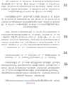
图1为本发明实施例中提供的显微手术术野三维重建系统架构示意图;FIG. 1 is a schematic diagram of the architecture of a three-dimensional reconstruction system for a microsurgery operating field provided in an embodiment of the present invention;
图2为本发明实施例中提供的显微手术术野三维重建系统硬件关系示意图;FIG. 2 is a schematic diagram of a hardware relationship of a 3D reconstruction system for a microsurgery operating field provided in an embodiment of the present invention;
图3为本发明实施例中提供的显微手术术野三维重建方法流程示意图。FIG. 3 is a schematic flowchart of a three-dimensional reconstruction method for a microsurgery operating field provided in an embodiment of the present invention.
具体实施方式Detailed ways
以下由特定的具体实施例说明本发明的实施方式,熟悉此技术的人士可由本说明书所揭露的内容轻易地了解本发明的其他优点及功效,显然,所描述的实施例是本发明一部分实施例,而不是全部的实施例。基于本发明中的实施例,本领域普通技术人员在没有做出创造性劳动前提下所获得的所有其他实施例,都属于本发明保护的范围。The embodiments of the present invention are described below by specific specific embodiments. Those who are familiar with the technology can easily understand other advantages and effects of the present invention from the contents disclosed in this specification. Obviously, the described embodiments are part of the present invention. , not all examples. Based on the embodiments of the present invention, all other embodiments obtained by those of ordinary skill in the art without creative efforts shall fall within the protection scope of the present invention.
参见图1和图2,提供一种显微手术术野三维重建系统,包括:Referring to Figures 1 and 2, a three-dimensional reconstruction system for a microsurgery operating field is provided, including:
可见光视点采集单元110:用于采集被测量场景的图案信息;所述可见光视点采集单元110包括第一感光元件111、第一光学变倍体113、第二感光元件112、第二光学变倍体114及主视野物镜116;Visible light viewpoint collection unit 110: used to collect pattern information of the scene to be measured; the visible light
所述第一感光元件111作为术野视点采集中的第一视角接收被测物体表面发出的光子并呈现被测物体在第一观测视角下的像;所述第一光学变倍体113采用光学变倍镜组改变被测物体在所述第一感光元件111上的放大倍率;The first
所述第二感光元件112作为术野视点采集中的第二视角接收被测物体表面发出的光子并呈现被测物体在第二观测视角下的像;所述第二光学变倍体114采用光学变倍镜组改变被测物体在所述第二感光元件112上的放大倍率;The second
所述主视野物镜116用于确定和改变由第一观测视角和第一观测视角的光路所形成的显微镜工作距离;The main field
红外光视点采集单元120:用于采集被测量场景的红外散斑图案;所述红外光视点采集单元120包括第一散斑投射器123、第一红外光学透镜组件122、第三感光元件121、第二散斑投射器126、第二红外光学透镜组件125和第四感光元件124;Infrared light viewpoint collection unit 120: used to collect the infrared speckle pattern of the measured scene; the infrared light
所述第一散斑投射器123用于投射激光散斑,所述激光散斑通过所述第一红外光学透镜组件122投射到被测物体表面形成具有给定图案形式的第一组红外散斑点;被测物体表面上的第一组红外散斑点反射后通过所述第一红外光学透镜组件122在所述第三感光元件上成像;The
所述第二散斑投射器126用于投射激光散斑,所述激光散斑通过所述第二红外光学透镜组件125投射到被测物体表面形成具有给定图案形式的第二组红外散斑点;被测物体表面上的第二组红外散斑点反射后通过所述第二红外光学透镜组件125在所述第四感光元件上成像;The
三维重建计算控制单元130:用于控制所述可见光视点采集单元110和红外光视点采集单元120的拍摄,并将所述可见光视点采集单元110得到的图案与所述红外光视点采集单元得到的图案进行信息融合,以获得三维重建结果。3D reconstruction calculation control unit 130: used to control the shooting of the visible light
具体的,所述可见光视点采集单元110还包括照明光源组件115,所述照明光源组件115用于给所述被测物体进行照明。照明光源组件115给被测物体提供充分照明,保证被测物体在第一感光元件111和第二感光元件112上的成像质量。Specifically, the visible light
具体的,第一感光元件111作为多视点采集中的第一观测视角用于接收被测物体表面发出的光子,最终呈现被测物体的在第一观测视角下的像,第一光学变倍体113是一套光学变倍镜组,该光学变倍镜组可以改变被测物体在第一感光元件111上的放大倍率;第二光学变倍体114和第二感光元件112作为被测物体的第二观测视角,其作用与第一观测视角完全相同,仅在观测物体的视角上存在差异。主视野物镜116用于确定和改变由第一观测视角和第二观测视角的光路所组成显微镜的工作距离。Specifically, the first
具体的,所述第一散斑投射器123、第一红外光学透镜组件122和第三感光元件121位于所述主视野物镜116的一侧;所述第二散斑投射器126、第二红外光学透镜组件125和第四感光元件124位于所述主视野物镜116的另外一侧。所述第一感光元件111和第二感光元件112采用对可见光感知的彩色感光元件;所述第三感光元件121和第四感光元件124采用对红外光的灰度感光元件。Specifically, the
红外光视点采集单元120由两路红外光采集装置构成,它们分别位于显微镜主体的两侧。以其中一路红外光采集装置为例,该采集装置由第三感光元件121、第一散斑投射器123和第一红外光学透镜组件122构成。第一散斑投射器123用于投射激光散斑,激光散斑通过第一红外光学透镜组件122投射到物体表面,形成具有特定图案形式的红外散斑点。物体表面上的散斑点反射后通过第一红外光学透镜组件122在第三感光元件上成像。The infrared light
具体的,第一红外光学透镜组件122有两个作用,一方面通过其内部的分光镜将散斑投射到物体表面,另一方面将物体表面反射的红外光通过第一红外光学透镜组件122投射到第三感光元件121上。第一红外光学透镜组件122的放大倍率与第一光学变倍体113的最小放大倍率相当。第三感光元件121、第一感光元件111和第二感光元件112在成像方式上略有不同,第三感光元件121是对红外感光的灰度感光元件,而第一感光元件111和第二感光元件112是对可见光感知的彩色感光元件。Specifically, the first infrared
具体的,在第一感光元件111和第二感光元件112设计上,和第三感光元件121有及第四感光元件124有着原理和功能上的差异。在原理上,第一感光元件111和第二感光元件112依靠可见光成像,第三感光元件121和第四感光元件124在红外光波段成像。功能上,由于第三感光元件121和第四感光元件124上都加装了散斑投射器,这使得第三感光元件121和第四感光元件124除了接收物体表面反射的照明光外还接收物体表面反射的散斑。这种设计的好处是,由于细小散斑的存在,第三感光元件121和第四感光元件124中原本无纹理和高光的区域得到细节加强,从而有效解决了立体匹配问题,使得红外光下三维重建的质量得到加强。Specifically, the design of the first
此外,需要指出的是,第一散斑投射器123和第二散斑投射器126发出的光属于红外波段,而第一感光元件111和第二感光元件112属于可见光成像,在红外波段的量子效率较低,因此散斑不会出现可见光感光元件对应的图像上。In addition, it should be pointed out that the light emitted by the
具体的。三维重建计算控制单元130包括同步相机131和计算设备132;所述同步相机131分别与所述第一感光元件111、第二感光元件112、第三感光元件121和第四感光元件124连接;所述计算设备132与所述同步相机131连接,计算设备132用于将第一感光元件111、第二感光元件112、第三感光元件121和第四感光元件124获得的数据进行处理得到最终的三维重建结果。同步相机131与四个感光元件连接,负责控制四个感光元件的同时拍摄。计算设备132将光学感光元件中得到的数据进行处理,得到最终的重建结果。specific. The three-dimensional reconstruction
参见图3,本发明还提供一种显微手术术野三维重建方法,用于上述的显微手术术野三维重建系统,包括以下步骤:Referring to FIG. 3 , the present invention also provides a method for three-dimensional reconstruction of a microsurgery operating field, which is used in the above-mentioned three-dimensional reconstruction system for a microsurgery operating field, including the following steps:
S1、对第一感光元件111、第二感光元件112、第三感光元件121和第四感光元件124在预设显微镜放大倍率下进行标定,获取第一感光元件111内参数


S2、在给定显微镜放大倍率i下,通过同步相机131控制第一感光元件111、第二感光元件112、第三感光元件121和第四感光元件124,使第一感光元件111、第二感光元件112、第三感光元件121和第四感光元件124同时拍摄被测物体,记录第一感光元件111所生成的图像


S3、采用第一感光元件111的内参数和外参数、第二感光元件112的内参数和外参数,利用计算机视觉中的立体校正算法对图像对


采用第三感光元件121的内参数和外参数、第四感光元件124的内参数和外参数,利用计算机视觉中的立体校正算法对图像对


S4、分别对所述校正图像对


S5、对所述校正图像对


对所述校正图像对


S6、采用所述空间点云P1和空间点云P2对无纹理区域的错误重建结果进行消除,以校正所述空间点云P1。S6. Use the spatial point cloud P1 and the spatial point cloud P2 to eliminate the erroneous reconstruction result of the textureless area, so as to correct the spatial point cloud P1 .
具体的,S5中,使用计算机视觉中的三角测量方法得到第一校正图像

其中(x,y)代表第一校正图像

具体的,S4中的稠密匹配算法使用稠密光流算法或基于深度学习的立体匹配算法。Specifically, the dense matching algorithm in S4 uses a dense optical flow algorithm or a deep learning-based stereo matching algorithm.
具体的,S6包括:Specifically, S6 includes:
S6.1、基于所述第三感光元件121与第一感光元件111的空间关系,将位于第三感光元件121坐标系中的空间点云P2变换到第一感光元件111的坐标系下,形成变换后的空间点云

P2在新坐标系下的模型为空间点云
S6.2、使用计算机视觉中的点云三角化对空间点云

S6.3、采用渲染后的空间点云
对于空间点云P1中的每个点P1t(X1t,Y1t,Z1t)获取临近点集合


使用最小二乘方法求出点P1t领域点的拟合平面Ax+By+Cz+D=0,得到点P1t处的法向量(A,B,C),再根据点向式方程,求出过P1t的且平行该点法向量的直线l:Use the least squares method to find the fitting plane Ax+By+Cz+D=0 of the point P1t field, get the normal vector (A, B, C) at the point P1t , and then according to the point-to-point equation, find A line l passing through P1t and parallel to the normal vector of the point:

然后将直线l与渲染后的空间点云
迭代上述过程完成空间点云P1中点的位置优化,得到可见光下的优化后的空间点云
本发明通过可见光视点采集单元110采集被测量场景的图案信息;通过红外光视点采集单元120采集被测量场景的红外散斑图案;采用三维重建计算控制单元130控制可见光视点采集单元110和红外光视点采集单元120的拍摄,并将可见光视点采集单元110得到的图案与红外光视点采集单元得到的图案进行信息融合,以获得三维重建结果。本技术方案将多视点联合优化和基于红外散斑的物体表面纹理增强机制引入高精度三维重建中,通过设计红外感光元件和散斑投射器的结构,可以精确地获取术野地外形结构,通过将该外形结构作为术野先验优化可见光下的三维重建模型,从而在不影响显微镜主光路的基础上提高了显微镜下的三维重建精度。The present invention collects the pattern information of the measured scene through the visible light
虽然,上文中已经用一般性说明及具体实施例对本发明作了详尽的描述,但在本发明基础上,可以对之作一些修改或改进,这对本领域技术人员而言是显而易见的。因此,在不偏离本发明精神的基础上所做的这些修改或改进,均属于本发明要求保护的范围。Although the present invention has been described in detail above with general description and specific embodiments, some modifications or improvements can be made on the basis of the present invention, which will be obvious to those skilled in the art. Therefore, these modifications or improvements made without departing from the spirit of the present invention fall within the scope of the claimed protection of the present invention.
Claims (8)


Priority Applications (1)
| Application Number | Priority Date | Filing Date | Title |
|---|---|---|---|
| CN202011084952.8ACN112294453B (en) | 2020-10-12 | 2020-10-12 | Microsurgery surgical field three-dimensional reconstruction system and method |
Applications Claiming Priority (1)
| Application Number | Priority Date | Filing Date | Title |
|---|---|---|---|
| CN202011084952.8ACN112294453B (en) | 2020-10-12 | 2020-10-12 | Microsurgery surgical field three-dimensional reconstruction system and method |
Publications (2)
| Publication Number | Publication Date |
|---|---|
| CN112294453A CN112294453A (en) | 2021-02-02 |
| CN112294453Btrue CN112294453B (en) | 2022-04-15 |
Family
ID=74489833
Family Applications (1)
| Application Number | Title | Priority Date | Filing Date |
|---|---|---|---|
| CN202011084952.8AActiveCN112294453B (en) | 2020-10-12 | 2020-10-12 | Microsurgery surgical field three-dimensional reconstruction system and method |
Country Status (1)
| Country | Link |
|---|---|
| CN (1) | CN112294453B (en) |
Families Citing this family (3)
| Publication number | Priority date | Publication date | Assignee | Title |
|---|---|---|---|---|
| CN113721359B (en)* | 2021-09-06 | 2024-07-05 | 戴朴 | System and method for real-time three-dimensional measurement of key indexes in ear microsurgery |
| CN114782631A (en)* | 2022-04-29 | 2022-07-22 | 四川中天鑫源生命科技有限公司 | Cell shadow picture formation of image VR dress equipment system |
| CN119984447A (en)* | 2025-03-12 | 2025-05-13 | 山东杰控电气技术有限公司 | A device for accurately measuring the liquid level of a mixing tank |
Citations (16)
| Publication number | Priority date | Publication date | Assignee | Title |
|---|---|---|---|---|
| CN103279987A (en)* | 2013-06-18 | 2013-09-04 | 厦门理工学院 | Object fast three-dimensional modeling method based on Kinect |
| CN103337071A (en)* | 2013-06-19 | 2013-10-02 | 北京理工大学 | Device and method for structure-reconstruction-based subcutaneous vein three-dimensional visualization |
| CN103337094A (en)* | 2013-06-14 | 2013-10-02 | 西安工业大学 | Method for realizing three-dimensional reconstruction of movement by using binocular camera |
| CN103810708A (en)* | 2014-02-13 | 2014-05-21 | 西安交通大学 | Method and device for perceiving depth of laser speckle image |
| CN105608734A (en)* | 2015-12-23 | 2016-05-25 | 王娟 | Three-dimensional image information acquisition apparatus and image reconstruction method therefor |
| CN106691491A (en)* | 2017-02-28 | 2017-05-24 | 赛诺威盛科技(北京)有限公司 | CT (computed tomography) positioning system implemented by using visible light and infrared light and CT positioning method |
| CN106875468A (en)* | 2015-12-14 | 2017-06-20 | 深圳先进技术研究院 | Three-dimensional reconstruction apparatus and method |
| CN108921027A (en)* | 2018-06-01 | 2018-11-30 | 杭州荣跃科技有限公司 | A kind of running disorder object recognition methods based on laser speckle three-dimensional reconstruction |
| CN109242812A (en)* | 2018-09-11 | 2019-01-18 | 中国科学院长春光学精密机械与物理研究所 | Image interfusion method and device based on conspicuousness detection and singular value decomposition |
| CN109903376A (en)* | 2019-02-28 | 2019-06-18 | 四川川大智胜软件股份有限公司 | A three-dimensional face modeling method and system assisted by face geometry information |
| CN110363806A (en)* | 2019-05-29 | 2019-10-22 | 中德(珠海)人工智能研究院有限公司 | A Method of Using Invisible Light Casting Features for 3D Space Modeling |
| CN110940295A (en)* | 2019-11-29 | 2020-03-31 | 北京理工大学 | High-reflection object measurement method and system based on laser speckle limit constraint projection |
| CN111009007A (en)* | 2019-11-20 | 2020-04-14 | 华南理工大学 | Finger multi-feature comprehensive three-dimensional reconstruction method |
| CN111145342A (en)* | 2019-12-27 | 2020-05-12 | 山东中科先进技术研究院有限公司 | A binocular speckle structured light three-dimensional reconstruction method and system |
| CN111260765A (en)* | 2020-01-13 | 2020-06-09 | 浙江未来技术研究院(嘉兴) | A Dynamic 3D Reconstruction Method of Microsurgery Field |
| CN111491151A (en)* | 2020-03-09 | 2020-08-04 | 浙江未来技术研究院(嘉兴) | Microsurgical stereoscopic video rendering method |
Family Cites Families (4)
| Publication number | Priority date | Publication date | Assignee | Title |
|---|---|---|---|---|
| US8970589B2 (en)* | 2011-02-10 | 2015-03-03 | Edge 3 Technologies, Inc. | Near-touch interaction with a stereo camera grid structured tessellations |
| US9141868B2 (en)* | 2012-06-26 | 2015-09-22 | Xerox Corporation | Contemporaneously reconstructing images captured of a scene illuminated with unstructured and structured illumination sources |
| CN105203044B (en)* | 2015-05-27 | 2019-06-11 | 珠海真幻科技有限公司 | To calculate stereo vision three-dimensional measurement method and system of the laser speckle as texture |
| CN111685711B (en)* | 2020-05-25 | 2023-01-03 | 中国科学院苏州生物医学工程技术研究所 | Medical endoscope three-dimensional imaging system based on 3D camera |
- 2020
- 2020-10-12CNCN202011084952.8Apatent/CN112294453B/enactiveActive
Patent Citations (16)
| Publication number | Priority date | Publication date | Assignee | Title |
|---|---|---|---|---|
| CN103337094A (en)* | 2013-06-14 | 2013-10-02 | 西安工业大学 | Method for realizing three-dimensional reconstruction of movement by using binocular camera |
| CN103279987A (en)* | 2013-06-18 | 2013-09-04 | 厦门理工学院 | Object fast three-dimensional modeling method based on Kinect |
| CN103337071A (en)* | 2013-06-19 | 2013-10-02 | 北京理工大学 | Device and method for structure-reconstruction-based subcutaneous vein three-dimensional visualization |
| CN103810708A (en)* | 2014-02-13 | 2014-05-21 | 西安交通大学 | Method and device for perceiving depth of laser speckle image |
| CN106875468A (en)* | 2015-12-14 | 2017-06-20 | 深圳先进技术研究院 | Three-dimensional reconstruction apparatus and method |
| CN105608734A (en)* | 2015-12-23 | 2016-05-25 | 王娟 | Three-dimensional image information acquisition apparatus and image reconstruction method therefor |
| CN106691491A (en)* | 2017-02-28 | 2017-05-24 | 赛诺威盛科技(北京)有限公司 | CT (computed tomography) positioning system implemented by using visible light and infrared light and CT positioning method |
| CN108921027A (en)* | 2018-06-01 | 2018-11-30 | 杭州荣跃科技有限公司 | A kind of running disorder object recognition methods based on laser speckle three-dimensional reconstruction |
| CN109242812A (en)* | 2018-09-11 | 2019-01-18 | 中国科学院长春光学精密机械与物理研究所 | Image interfusion method and device based on conspicuousness detection and singular value decomposition |
| CN109903376A (en)* | 2019-02-28 | 2019-06-18 | 四川川大智胜软件股份有限公司 | A three-dimensional face modeling method and system assisted by face geometry information |
| CN110363806A (en)* | 2019-05-29 | 2019-10-22 | 中德(珠海)人工智能研究院有限公司 | A Method of Using Invisible Light Casting Features for 3D Space Modeling |
| CN111009007A (en)* | 2019-11-20 | 2020-04-14 | 华南理工大学 | Finger multi-feature comprehensive three-dimensional reconstruction method |
| CN110940295A (en)* | 2019-11-29 | 2020-03-31 | 北京理工大学 | High-reflection object measurement method and system based on laser speckle limit constraint projection |
| CN111145342A (en)* | 2019-12-27 | 2020-05-12 | 山东中科先进技术研究院有限公司 | A binocular speckle structured light three-dimensional reconstruction method and system |
| CN111260765A (en)* | 2020-01-13 | 2020-06-09 | 浙江未来技术研究院(嘉兴) | A Dynamic 3D Reconstruction Method of Microsurgery Field |
| CN111491151A (en)* | 2020-03-09 | 2020-08-04 | 浙江未来技术研究院(嘉兴) | Microsurgical stereoscopic video rendering method |
Also Published As
| Publication number | Publication date |
|---|---|
| CN112294453A (en) | 2021-02-02 |
Similar Documents
| Publication | Publication Date | Title |
|---|---|---|
| JP7379704B2 (en) | System and method for integrating visualization camera and optical coherence tomography | |
| CN112294453B (en) | Microsurgery surgical field three-dimensional reconstruction system and method | |
| US12349972B2 (en) | Surgical applications with integrated visualization camera and optical coherence tomography | |
| CN113108721B (en) | High-reflectivity object three-dimensional measurement method based on multi-beam self-adaptive complementary matching | |
| CN110288642A (en) | Fast reconstruction method of 3D object based on camera array | |
| JP6458732B2 (en) | Image processing apparatus, image processing method, and program | |
| CN113052898B (en) | A real-time localization method of point cloud and strong reflective target based on active binocular camera | |
| US20160295194A1 (en) | Stereoscopic vision system generatng stereoscopic images with a monoscopic endoscope and an external adapter lens and method using the same to generate stereoscopic images | |
| CN109186491A (en) | Parallel multi-thread laser measurement system and measurement method based on homography matrix | |
| WO2017008226A1 (en) | Three-dimensional facial reconstruction method and system | |
| TWI697317B (en) | Digital image reality alignment kit and method applied to mixed reality system for surgical navigation | |
| CN114886558A (en) | Endoscope projection method and system based on augmented reality | |
| WO2018032841A1 (en) | Method, device and system for drawing three-dimensional image | |
| CN1544883A (en) | Three-dimensional foot type measuring and modeling method based on specific grid pattern | |
| WO2023220605A2 (en) | Methods and systems for calibrating instruments within an imaging system, such as a surgical imaging system | |
| CN106303501B (en) | Stereo-picture reconstructing method and device based on image sparse characteristic matching | |
| CN114264253B (en) | Device and method for non-contact measurement of three-dimensional profile of high-temperature object | |
| CN117765042A (en) | Registration method and device for oral tomographic image, computer equipment and storage medium | |
| CN112804515A (en) | Omnidirectional stereoscopic vision camera configuration system and camera configuration method | |
| WO2023165451A1 (en) | Three-dimensional model creation method, endoscope, and storage medium | |
| CN115861542A (en) | A binocular multi-line three-dimensional reconstruction method and system | |
| CN115623163A (en) | Two-dimensional and three-dimensional image acquisition and fusion display system and method | |
| CN212163540U (en) | Omnidirectional stereoscopic vision camera configuration system | |
| CN111481293A (en) | Multi-viewpoint optical positioning method and system based on optimal viewpoint selection | |
| Guo et al. | An accurate speckle 3d reconstruction system based on binocular endoscope |
Legal Events
| Date | Code | Title | Description |
|---|---|---|---|
| PB01 | Publication | ||
| PB01 | Publication | ||
| SE01 | Entry into force of request for substantive examination | ||
| SE01 | Entry into force of request for substantive examination | ||
| GR01 | Patent grant | ||
| GR01 | Patent grant | ||
| TR01 | Transfer of patent right | ||
| TR01 | Transfer of patent right | Effective date of registration:20240311 Address after:314050 9F, No. 705, Asia Pacific Road, Nanhu District, Jiaxing City, Zhejiang Province Patentee after:ZHEJIANG YANGTZE DELTA REGION INSTITUTE OF TSINGHUA University Country or region after:China Address before:No.152 Huixin Road, Nanhu District, Jiaxing City, Zhejiang Province 314000 Patentee before:ZHEJIANG FUTURE TECHNOLOGY INSTITUTE (JIAXING) Country or region before:China | |
| TR01 | Transfer of patent right | ||
| TR01 | Transfer of patent right | Effective date of registration:20241121 Address after:314000 room 307, building 1, No. 152, Huixin Road, Daqiao Town, Nanhu District, Jiaxing City, Zhejiang Province Patentee after:Jiaxing Zhitong Technology Co.,Ltd. Country or region after:China Address before:314050 9F, No. 705, Asia Pacific Road, Nanhu District, Jiaxing City, Zhejiang Province Patentee before:ZHEJIANG YANGTZE DELTA REGION INSTITUTE OF TSINGHUA University Country or region before:China |