CN112294299A - Biosensor implanting device and implanting method thereof - Google Patents
Biosensor implanting device and implanting method thereofDownload PDFInfo
- Publication number
- CN112294299A CN112294299ACN202010028037.0ACN202010028037ACN112294299ACN 112294299 ACN112294299 ACN 112294299ACN 202010028037 ACN202010028037 ACN 202010028037ACN 112294299 ACN112294299 ACN 112294299A
- Authority
- CN
- China
- Prior art keywords
- implantation
- needle
- seat
- implanting
- biosensor
- Prior art date
- Legal status (The legal status is an assumption and is not a legal conclusion. Google has not performed a legal analysis and makes no representation as to the accuracy of the status listed.)
- Granted
Links
- 238000000034methodMethods0.000titleclaimsabstractdescription52
- 238000002513implantationMethods0.000claimsabstractdescription380
- 239000007943implantSubstances0.000claimsabstractdescription147
- 238000006073displacement reactionMethods0.000claimsdescription32
- 239000002274desiccantSubstances0.000claimsdescription14
- 230000001681protective effectEffects0.000claimsdescription10
- 230000002093peripheral effectEffects0.000claimsdescription8
- 230000006835compressionEffects0.000claimsdescription6
- 238000007906compressionMethods0.000claimsdescription6
- 238000001035dryingMethods0.000claimsdescription5
- 238000007920subcutaneous administrationMethods0.000claims2
- 238000000605extractionMethods0.000abstractdescription84
- 230000001953sensory effectEffects0.000abstractdescription8
- 239000003153chemical reaction reagentSubstances0.000abstractdescription4
- 238000010586diagramMethods0.000description15
- 239000000853adhesiveSubstances0.000description14
- 230000001070adhesive effectEffects0.000description14
- 230000000694effectsEffects0.000description5
- 239000002390adhesive tapeSubstances0.000description3
- 230000000903blocking effectEffects0.000description2
- 239000002906medical wasteSubstances0.000description2
- WQZGKKKJIJFFOK-GASJEMHNSA-NGlucoseNatural productsOC[C@H]1OC(O)[C@H](O)[C@@H](O)[C@@H]1OWQZGKKKJIJFFOK-GASJEMHNSA-N0.000description1
- XAGFODPZIPBFFR-UHFFFAOYSA-NaluminiumChemical compound[Al]XAGFODPZIPBFFR-UHFFFAOYSA-N0.000description1
- 229910052782aluminiumInorganic materials0.000description1
- 230000009286beneficial effectEffects0.000description1
- 238000006243chemical reactionMethods0.000description1
- 238000001514detection methodMethods0.000description1
- 239000013013elastic materialSubstances0.000description1
- 239000011888foilSubstances0.000description1
- 239000008103glucoseSubstances0.000description1
- 238000003780insertionMethods0.000description1
- 230000037431insertionEffects0.000description1
- 210000001503jointAnatomy0.000description1
- 239000000463materialSubstances0.000description1
- 238000007789sealingMethods0.000description1
- 238000000926separation methodMethods0.000description1
- 239000002699waste materialSubstances0.000description1
Images


Classifications
- A—HUMAN NECESSITIES
- A61—MEDICAL OR VETERINARY SCIENCE; HYGIENE
- A61B—DIAGNOSIS; SURGERY; IDENTIFICATION
- A61B5/00—Measuring for diagnostic purposes; Identification of persons
- A61B5/145—Measuring characteristics of blood in vivo, e.g. gas concentration or pH-value ; Measuring characteristics of body fluids or tissues, e.g. interstitial fluid or cerebral tissue
- A61B5/14532—Measuring characteristics of blood in vivo, e.g. gas concentration or pH-value ; Measuring characteristics of body fluids or tissues, e.g. interstitial fluid or cerebral tissue for measuring glucose, e.g. by tissue impedance measurement
- A—HUMAN NECESSITIES
- A61—MEDICAL OR VETERINARY SCIENCE; HYGIENE
- A61B—DIAGNOSIS; SURGERY; IDENTIFICATION
- A61B5/00—Measuring for diagnostic purposes; Identification of persons
- A61B5/0002—Remote monitoring of patients using telemetry, e.g. transmission of vital signals via a communication network
- A61B5/0004—Remote monitoring of patients using telemetry, e.g. transmission of vital signals via a communication network characterised by the type of physiological signal transmitted
- A—HUMAN NECESSITIES
- A61—MEDICAL OR VETERINARY SCIENCE; HYGIENE
- A61B—DIAGNOSIS; SURGERY; IDENTIFICATION
- A61B5/00—Measuring for diagnostic purposes; Identification of persons
- A61B5/145—Measuring characteristics of blood in vivo, e.g. gas concentration or pH-value ; Measuring characteristics of body fluids or tissues, e.g. interstitial fluid or cerebral tissue
- A61B5/14503—Measuring characteristics of blood in vivo, e.g. gas concentration or pH-value ; Measuring characteristics of body fluids or tissues, e.g. interstitial fluid or cerebral tissue invasive, e.g. introduced into the body by a catheter or needle or using implanted sensors
- A—HUMAN NECESSITIES
- A61—MEDICAL OR VETERINARY SCIENCE; HYGIENE
- A61B—DIAGNOSIS; SURGERY; IDENTIFICATION
- A61B5/00—Measuring for diagnostic purposes; Identification of persons
- A61B5/145—Measuring characteristics of blood in vivo, e.g. gas concentration or pH-value ; Measuring characteristics of body fluids or tissues, e.g. interstitial fluid or cerebral tissue
- A61B5/14507—Measuring characteristics of blood in vivo, e.g. gas concentration or pH-value ; Measuring characteristics of body fluids or tissues, e.g. interstitial fluid or cerebral tissue specially adapted for measuring characteristics of body fluids other than blood
- A61B5/1451—Measuring characteristics of blood in vivo, e.g. gas concentration or pH-value ; Measuring characteristics of body fluids or tissues, e.g. interstitial fluid or cerebral tissue specially adapted for measuring characteristics of body fluids other than blood for interstitial fluid
- A—HUMAN NECESSITIES
- A61—MEDICAL OR VETERINARY SCIENCE; HYGIENE
- A61B—DIAGNOSIS; SURGERY; IDENTIFICATION
- A61B5/00—Measuring for diagnostic purposes; Identification of persons
- A61B5/145—Measuring characteristics of blood in vivo, e.g. gas concentration or pH-value ; Measuring characteristics of body fluids or tissues, e.g. interstitial fluid or cerebral tissue
- A61B5/14546—Measuring characteristics of blood in vivo, e.g. gas concentration or pH-value ; Measuring characteristics of body fluids or tissues, e.g. interstitial fluid or cerebral tissue for measuring analytes not otherwise provided for, e.g. ions, cytochromes
- A—HUMAN NECESSITIES
- A61—MEDICAL OR VETERINARY SCIENCE; HYGIENE
- A61B—DIAGNOSIS; SURGERY; IDENTIFICATION
- A61B5/00—Measuring for diagnostic purposes; Identification of persons
- A61B5/145—Measuring characteristics of blood in vivo, e.g. gas concentration or pH-value ; Measuring characteristics of body fluids or tissues, e.g. interstitial fluid or cerebral tissue
- A61B5/1468—Measuring characteristics of blood in vivo, e.g. gas concentration or pH-value ; Measuring characteristics of body fluids or tissues, e.g. interstitial fluid or cerebral tissue using chemical or electrochemical methods, e.g. by polarographic means
- A61B5/1486—Measuring characteristics of blood in vivo, e.g. gas concentration or pH-value ; Measuring characteristics of body fluids or tissues, e.g. interstitial fluid or cerebral tissue using chemical or electrochemical methods, e.g. by polarographic means using enzyme electrodes, e.g. with immobilised oxidase
- A61B5/14865—Measuring characteristics of blood in vivo, e.g. gas concentration or pH-value ; Measuring characteristics of body fluids or tissues, e.g. interstitial fluid or cerebral tissue using chemical or electrochemical methods, e.g. by polarographic means using enzyme electrodes, e.g. with immobilised oxidase invasive, e.g. introduced into the body by a catheter or needle or using implanted sensors
- A—HUMAN NECESSITIES
- A61—MEDICAL OR VETERINARY SCIENCE; HYGIENE
- A61B—DIAGNOSIS; SURGERY; IDENTIFICATION
- A61B5/00—Measuring for diagnostic purposes; Identification of persons
- A61B5/15—Devices for taking samples of blood
- A61B5/150007—Details
- A61B5/150748—Having means for aiding positioning of the piercing device at a location where the body is to be pierced
- A—HUMAN NECESSITIES
- A61—MEDICAL OR VETERINARY SCIENCE; HYGIENE
- A61B—DIAGNOSIS; SURGERY; IDENTIFICATION
- A61B5/00—Measuring for diagnostic purposes; Identification of persons
- A61B5/15—Devices for taking samples of blood
- A61B5/150007—Details
- A61B5/150847—Communication to or from blood sampling device
- A—HUMAN NECESSITIES
- A61—MEDICAL OR VETERINARY SCIENCE; HYGIENE
- A61B—DIAGNOSIS; SURGERY; IDENTIFICATION
- A61B5/00—Measuring for diagnostic purposes; Identification of persons
- A61B5/68—Arrangements of detecting, measuring or recording means, e.g. sensors, in relation to patient
- A61B5/6801—Arrangements of detecting, measuring or recording means, e.g. sensors, in relation to patient specially adapted to be attached to or worn on the body surface
- A61B5/683—Means for maintaining contact with the body
- A61B5/6832—Means for maintaining contact with the body using adhesives
- A61B5/6833—Adhesive patches
- A—HUMAN NECESSITIES
- A61—MEDICAL OR VETERINARY SCIENCE; HYGIENE
- A61B—DIAGNOSIS; SURGERY; IDENTIFICATION
- A61B5/00—Measuring for diagnostic purposes; Identification of persons
- A61B5/68—Arrangements of detecting, measuring or recording means, e.g. sensors, in relation to patient
- A61B5/6846—Arrangements of detecting, measuring or recording means, e.g. sensors, in relation to patient specially adapted to be brought in contact with an internal body part, i.e. invasive
- A61B5/6847—Arrangements of detecting, measuring or recording means, e.g. sensors, in relation to patient specially adapted to be brought in contact with an internal body part, i.e. invasive mounted on an invasive device
- A61B5/6848—Needles
- A61B5/6849—Needles in combination with a needle set
- A—HUMAN NECESSITIES
- A61—MEDICAL OR VETERINARY SCIENCE; HYGIENE
- A61B—DIAGNOSIS; SURGERY; IDENTIFICATION
- A61B5/00—Measuring for diagnostic purposes; Identification of persons
- A61B5/68—Arrangements of detecting, measuring or recording means, e.g. sensors, in relation to patient
- A61B5/6846—Arrangements of detecting, measuring or recording means, e.g. sensors, in relation to patient specially adapted to be brought in contact with an internal body part, i.e. invasive
- A61B5/6867—Arrangements of detecting, measuring or recording means, e.g. sensors, in relation to patient specially adapted to be brought in contact with an internal body part, i.e. invasive specially adapted to be attached or implanted in a specific body part
- A—HUMAN NECESSITIES
- A61—MEDICAL OR VETERINARY SCIENCE; HYGIENE
- A61B—DIAGNOSIS; SURGERY; IDENTIFICATION
- A61B5/00—Measuring for diagnostic purposes; Identification of persons
- A61B5/68—Arrangements of detecting, measuring or recording means, e.g. sensors, in relation to patient
- A61B5/6846—Arrangements of detecting, measuring or recording means, e.g. sensors, in relation to patient specially adapted to be brought in contact with an internal body part, i.e. invasive
- A61B5/6879—Means for maintaining contact with the body
- A61B5/688—Means for maintaining contact with the body using adhesives
- A—HUMAN NECESSITIES
- A61—MEDICAL OR VETERINARY SCIENCE; HYGIENE
- A61B—DIAGNOSIS; SURGERY; IDENTIFICATION
- A61B2560/00—Constructional details of operational features of apparatus; Accessories for medical measuring apparatus
- A61B2560/04—Constructional details of apparatus
- A61B2560/0443—Modular apparatus
- A61B2560/045—Modular apparatus with a separable interface unit, e.g. for communication
- A—HUMAN NECESSITIES
- A61—MEDICAL OR VETERINARY SCIENCE; HYGIENE
- A61B—DIAGNOSIS; SURGERY; IDENTIFICATION
- A61B2560/00—Constructional details of operational features of apparatus; Accessories for medical measuring apparatus
- A61B2560/06—Accessories for medical measuring apparatus
- A61B2560/063—Devices specially adapted for delivering implantable medical measuring apparatus
- A—HUMAN NECESSITIES
- A61—MEDICAL OR VETERINARY SCIENCE; HYGIENE
- A61B—DIAGNOSIS; SURGERY; IDENTIFICATION
- A61B2562/00—Details of sensors; Constructional details of sensor housings or probes; Accessories for sensors
- A61B2562/02—Details of sensors specially adapted for in-vivo measurements
- A61B2562/0295—Strip shaped analyte sensors for apparatus classified in A61B5/145 or A61B5/157
- A—HUMAN NECESSITIES
- A61—MEDICAL OR VETERINARY SCIENCE; HYGIENE
- A61B—DIAGNOSIS; SURGERY; IDENTIFICATION
- A61B2562/00—Details of sensors; Constructional details of sensor housings or probes; Accessories for sensors
- A61B2562/14—Coupling media or elements to improve sensor contact with skin or tissue
- A—HUMAN NECESSITIES
- A61—MEDICAL OR VETERINARY SCIENCE; HYGIENE
- A61B—DIAGNOSIS; SURGERY; IDENTIFICATION
- A61B2562/00—Details of sensors; Constructional details of sensor housings or probes; Accessories for sensors
- A61B2562/16—Details of sensor housings or probes; Details of structural supports for sensors
- A61B2562/166—Details of sensor housings or probes; Details of structural supports for sensors the sensor is mounted on a specially adapted printed circuit board
- A—HUMAN NECESSITIES
- A61—MEDICAL OR VETERINARY SCIENCE; HYGIENE
- A61B—DIAGNOSIS; SURGERY; IDENTIFICATION
- A61B2562/00—Details of sensors; Constructional details of sensor housings or probes; Accessories for sensors
- A61B2562/16—Details of sensor housings or probes; Details of structural supports for sensors
- A61B2562/168—Fluid filled sensor housings
- A—HUMAN NECESSITIES
- A61—MEDICAL OR VETERINARY SCIENCE; HYGIENE
- A61B—DIAGNOSIS; SURGERY; IDENTIFICATION
- A61B2562/00—Details of sensors; Constructional details of sensor housings or probes; Accessories for sensors
- A61B2562/22—Arrangements of medical sensors with cables or leads; Connectors or couplings specifically adapted for medical sensors
- A61B2562/225—Connectors or couplings
- A61B2562/226—Connectors or couplings comprising means for identifying the connector, e.g. to prevent incorrect connection to socket
- A—HUMAN NECESSITIES
- A61—MEDICAL OR VETERINARY SCIENCE; HYGIENE
- A61B—DIAGNOSIS; SURGERY; IDENTIFICATION
- A61B2562/00—Details of sensors; Constructional details of sensor housings or probes; Accessories for sensors
- A61B2562/22—Arrangements of medical sensors with cables or leads; Connectors or couplings specifically adapted for medical sensors
- A61B2562/225—Connectors or couplings
- A61B2562/227—Sensors with electrical connectors
- A—HUMAN NECESSITIES
- A61—MEDICAL OR VETERINARY SCIENCE; HYGIENE
- A61B—DIAGNOSIS; SURGERY; IDENTIFICATION
- A61B2562/00—Details of sensors; Constructional details of sensor housings or probes; Accessories for sensors
- A61B2562/24—Hygienic packaging for medical sensors; Maintaining apparatus for sensor hygiene
- A61B2562/242—Packaging, i.e. for packaging the sensor or apparatus before use
- H—ELECTRICITY
- H01—ELECTRIC ELEMENTS
- H01R—ELECTRICALLY-CONDUCTIVE CONNECTIONS; STRUCTURAL ASSOCIATIONS OF A PLURALITY OF MUTUALLY-INSULATED ELECTRICAL CONNECTING ELEMENTS; COUPLING DEVICES; CURRENT COLLECTORS
- H01R12/00—Structural associations of a plurality of mutually-insulated electrical connecting elements, specially adapted for printed circuits, e.g. printed circuit boards [PCB], flat or ribbon cables, or like generally planar structures, e.g. terminal strips, terminal blocks; Coupling devices specially adapted for printed circuits, flat or ribbon cables, or like generally planar structures; Terminals specially adapted for contact with, or insertion into, printed circuits, flat or ribbon cables, or like generally planar structures
- H01R12/70—Coupling devices
- H01R12/71—Coupling devices for rigid printing circuits or like structures
- H01R12/72—Coupling devices for rigid printing circuits or like structures coupling with the edge of the rigid printed circuits or like structures
- H01R12/73—Coupling devices for rigid printing circuits or like structures coupling with the edge of the rigid printed circuits or like structures connecting to other rigid printed circuits or like structures
- H01R12/735—Printed circuits including an angle between each other
- H01R12/737—Printed circuits being substantially perpendicular to each other
Landscapes
- Health & Medical Sciences (AREA)
- Life Sciences & Earth Sciences (AREA)
- Physics & Mathematics (AREA)
- Engineering & Computer Science (AREA)
- Animal Behavior & Ethology (AREA)
- Veterinary Medicine (AREA)
- Biomedical Technology (AREA)
- Heart & Thoracic Surgery (AREA)
- Public Health (AREA)
- General Health & Medical Sciences (AREA)
- Pathology (AREA)
- Surgery (AREA)
- Molecular Biology (AREA)
- Medical Informatics (AREA)
- Biophysics (AREA)
- Optics & Photonics (AREA)
- Emergency Medicine (AREA)
- Computer Networks & Wireless Communication (AREA)
- Chemical Kinetics & Catalysis (AREA)
- General Chemical & Material Sciences (AREA)
- Chemical & Material Sciences (AREA)
- Hematology (AREA)
- Vascular Medicine (AREA)
- Physiology (AREA)
- Measurement Of The Respiration, Hearing Ability, Form, And Blood Characteristics Of Living Organisms (AREA)
- Measuring And Recording Apparatus For Diagnosis (AREA)
- Anesthesiology (AREA)
- Measuring Pulse, Heart Rate, Blood Pressure Or Blood Flow (AREA)
- Media Introduction/Drainage Providing Device (AREA)
- Infusion, Injection, And Reservoir Apparatuses (AREA)
- Seats For Vehicles (AREA)
- Electrotherapy Devices (AREA)
- Inspection Of Paper Currency And Valuable Securities (AREA)
- Auxiliary Devices For And Details Of Packaging Control (AREA)
- Automotive Seat Belt Assembly (AREA)
Abstract
Translated fromChinese
Description
Translated fromChinese技术领域technical field
本发明涉及一种生物传感器的植入装置及其植入方法,特别是涉及一种将能量测葡萄糖值的感测试片植入生物皮下并持续获取生理讯号。The present invention relates to a biosensor implantation device and an implantation method thereof, in particular to a biosensor subcutaneously implanting a sensory test piece capable of measuring glucose value and continuously acquiring physiological signals.
背景技术Background technique
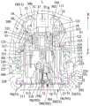
现有一种能将感测试片植入生物皮下的植入装置(US10,413,183专利案),植入装置5000包括一个锁环座5004、一个能滑动的穿设于锁环座5004内部的柱塞5002、一个安装于该柱塞5002内部的撞针座5136、一个安装于该柱塞5002与撞针座5136之间的非预压撞针弹簧5138、一个套设于撞针座5136内部的针座5146、一个弹抵于撞针座5136与针座5146之间的针座弹簧5144,以及一个传感器5108。There is an existing implant device (US10,413,183 patent case) capable of implanting a sensory test piece under the skin. The implant device 5000 includes a lock ring seat 5004 and a plunger slidably penetrated inside the lock ring seat 5004 5002, a striker base 5136 installed inside the plunger 5002, a non-pre-compressed striker spring 5138 installed between the plunger 5002 and the striker base 5136, a needle base 5146 sleeved inside the striker base 5136, a A needle seat spring 5144 that bounces between the striker seat 5136 and the needle seat 5146 , and a sensor 5108 .
前案的植入装置欲操作植针时,使用者必需压下柱塞5002,使非预压缩的撞针弹簧5138产生压缩状态,并利用柱塞肋5152使所对应的卡扣臂5142偏转,解除柱塞肋515与卡扣臂5142的限位关系,利用非预压缩撞针弹簧5138的弹力恢复带动撞针座5136及针座5146向下进行植针。When the implantation device of the previous case wants to operate the implantation needle, the user must depress the plunger 5002 to make the non-precompressed striker spring 5138 into a compressed state, and use the plunger rib 5152 to deflect the corresponding latching arm 5142 to release the The position-limiting relationship between the plunger rib 515 and the locking arm 5142 utilizes the elastic force of the non-precompressed striker spring 5138 to restore the striker seat 5136 and the needle seat 5146 for needle implantation.
当完成植针后,撞针座5136仍然处于植针位置时,此时,使用者必须放开对柱塞5002的下压,使柱塞5002向上移动,解除针座5146的限位关系,再利用预压缩的针座弹簧5144的弹力释放使针座5146带动刺穿构件5110朝柱塞5002内部缩回,传感器5108留置于人体皮肤表面。After the needle is implanted, the striker seat 5136 is still at the needle-planting position. At this time, the user must release the pressure on the plunger 5002 to move the plunger 5002 upward, release the limit relationship of the needle seat 5146, and then use it again. The release of the elastic force of the pre-compressed needle hub spring 5144 causes the needle hub 5146 to drive the piercing member 5110 to retract toward the inside of the plunger 5002, and the sensor 5108 remains on the surface of the human skin.
换言之,前案的植入装置虽然能完成植针、抽针的,但是在植针方面是借由使用者的手部下压力道才能将刺穿构件5110刺入人体皮肤表面,而且在进行抽针时,使用者必须放开柱塞5002,针座5146才会再带动刺穿构件5110朝柱塞5002内部缩回。据此,前案的植针、抽针方式为两段式操作并且不属于弹力植针的方式,更甚者,会因为使用者的熟练程度而影响植、抽针的顺畅度,对于比较没有操作经验的操作者而言,可能在下压柱塞5002后若没有放开对柱塞的施力,将使得刺穿构件5110持续停留在使用者的皮下,可能增加使用者的不适感。In other words, although the implantation device in the previous case can complete needle implantation and needle extraction, in terms of needle implantation, the piercing member 5110 can be pierced into the human skin surface only by the downward pressure channel of the user's hand, and the needle extraction is performed during needle extraction. At this time, the user must release the plunger 5002, and the needle seat 5146 will drive the piercing member 5110 to retract toward the inside of the plunger 5002 again. Accordingly, the method of needle implantation and needle extraction in the previous case is a two-stage operation and does not belong to the method of elastic needle implantation. What's more, the smoothness of needle implantation and needle extraction will be affected due to the user's proficiency. For operators with operating experience, if the force on the plunger is not released after pressing the plunger 5002, the piercing member 5110 will continue to stay under the user's skin, which may increase the user's discomfort.
也就是说,前案的植入装置会因为使用作者的操作熟练度,造成操作上的不确定性以及对使用者产生不适感。That is to say, the implantation device in the previous case will cause operational uncertainty and discomfort to the user due to the user's operational proficiency.
发明内容SUMMARY OF THE INVENTION
本发明的一个目的在于提供一种操作顺畅并且借由弹力植针方式降低使用者在自动植针与自动抽针上的不适感的生物传感器的植入装置及其植入方法,并且完成自动植针及自动抽针的时间不大于100毫秒。An object of the present invention is to provide a biosensor implantation device and an implantation method thereof that can operate smoothly and reduce the user's discomfort on automatic needle implantation and automatic needle extraction by means of elastic needle implantation, and complete the automatic implantation. The time for needle and automatic needle extraction is not more than 100 milliseconds.
本发明的另一个目的,在于提供一种借由底盖与上盖构成防误植针结构的植入装置,能避免植入装置在搬运时不慎掉落造成误植针的情况。Another object of the present invention is to provide an implantation device with a bottom cover and an upper cover to form an anti-incorrect needle implantation structure, which can avoid the accidental needle implantation caused by the accidental drop of the implantation device during transportation.
本发明的再另一个目的,在于提供一种借由底盖与上盖结合后于植入装置内部产生气密空间,并能依实际需求于气密空间内部适当处设置干燥剂,防止传感器组件上感测试片的化学试剂潮湿。Still another object of the present invention is to provide an air-tight space inside the implanted device by combining the bottom cover and the upper cover, and a desiccant can be appropriately placed inside the air-tight space according to actual requirements to prevent the sensor assembly The chemical reagent on the test strip is wet.
本发明的生物传感器的植入装置,包含上盖及植入模组,The implantation device of the biosensor of the present invention comprises an upper cover and an implantation module,
所述上盖,具有容置空间;the upper cover has an accommodating space;
所述植入模组,设置于所述上盖的容置空间中;The implantation module is arranged in the accommodating space of the upper cover;
所述植入模组包括:The implantation module includes:
主体组件,具有顶部、底部及介于所述顶部及所述底部之间的位移空间;a main body assembly having a top, a bottom and a displacement space between the top and the bottom;
植入座,能卸离且限位于所述主体组件的顶部,并可于所述顶部及所述底部之间位移;an implant seat, which can be detached and limited to the top of the main body assembly, and can be displaced between the top and the bottom;
第一弹性件,弹抵于所述植入座所述主体组件的顶部之间;a first elastic member, which springs against the top of the main body assembly of the implant seat;
抽针座,能卸离且限位于所述植入座;A needle extraction seat, which can be detached and limited to the implant seat;
第二弹性件,弹抵于所述植入座与所述抽针座之间;a second elastic member that springs against the implant seat and the needle extraction seat;
底座,能卸离且限位于所述主体组件;a base, which can be detached and limited to the main body assembly;
传感器组件,能卸离的限位于所述底座;The sensor assembly, the detachable limit is located on the base;
其中,下压所述上盖,使所述植入座借由所述第一弹性件的弹力释放向下位移至解除与所述主体组件的顶部的限位关系,而进行自动植针,当完成自动植针时,在所述上盖仍然处于下压的状态,所述植入座与所述主体组件的顶部的限位关系解除,且所述植入座与所述抽针座的限位关系解除,使所述抽针座借由所述第二弹性件的弹力释放向上位移完成自动抽针。The upper cover is pressed down to make the implant seat displace downward by the release of the elastic force of the first elastic member to release the limiting relationship with the top of the main body assembly, so as to perform automatic needle implantation. When the automatic needle implantation is completed, the upper cover is still in a downward pressure state, the limiting relationship between the implantation seat and the top of the main body assembly is released, and the limiting relationship between the implantation seat and the needle extraction seat is released. The position relationship is released, so that the needle extraction seat is displaced upward by the release of the elastic force of the second elastic member to complete the automatic needle extraction.
本发明的生物传感器的植入装置,所述主体组件包括主体件及主体盖,所述主体件对应所述主体组件的底部,所述主体盖对应所述主体组件的顶部,所述主体盖与所述主体件共同界定出所述位移空间。In the biosensor implantation device of the present invention, the main body assembly includes a main body part and a main body cover, the main body part corresponds to the bottom of the main body assembly, the main body cover corresponds to the top of the main body assembly, and the main body cover is connected with The main body parts together define the displacement space.
本发明的生物传感器的植入装置,所述上盖包括外壳件,以及与所述外壳件同动的罩体,且所述抽针座及所述植入座分别具有植针件及推掣部,当所述植入模组进行植针后,所述植针件穿设所述底座而将感测试片植入于生物皮下,所述植入座的推掣部则紧密抵设所述传感器组件,避免所述传感器组件在植针瞬间脱离所述底座的传感器组件定位部。In the biosensor implantation device of the present invention, the upper cover includes a housing member and a cover body that moves together with the housing member, and the needle extraction seat and the implantation seat respectively have a needle implantation member and a pusher part, after the implantation module performs needle implantation, the needle implantation member penetrates the base to implant the sensing test piece under the biological skin, and the pusher part of the implantation seat tightly abuts against the The sensor assembly prevents the sensor assembly from being separated from the sensor assembly positioning portion of the base at the moment of needle implantation.
本发明的生物传感器的植入装置,所述植入模组的植入座与所述主体盖分别具有互相限位的限位槽及限位件,以及所述植入座还具有使所述抽针座相对于所述植入座保持限位的限位组件,借由上述结构相互设置,使所述植入座、所述上盖及所述抽针座构成抽针限位结构。In the biosensor implant device of the present invention, the implant seat of the implant module and the main body cover respectively have a limit groove and a limit piece that limit each other, and the implant seat also has a The position-limiting components of the needle-extraction seat to keep the position-limited position relative to the implantation seat are mutually arranged by the above-mentioned structure, so that the implantation seat, the upper cover and the needle-extraction seat constitute a needle-extraction limit structure.
本发明的生物传感器的植入装置,所述上盖的内周面具有至少一个掣动部,所述主体件具有至少一个扣止部,所述植入座具有至少一个受所述掣动部掣动且能脱离并嵌制于所述主体件的扣止部的卡扣部,借由上述结构相互设置,使所述植入座与所述主体件间构成植针限位结构。In the biosensor implantation device of the present invention, the inner peripheral surface of the upper cover has at least one latching portion, the main body has at least one latching portion, and the implant base has at least one latching portion. The latching portion which is locked and can be disengaged and embedded in the latching portion of the main body is mutually arranged by the above-mentioned structure, so that the implantation seat and the main body constitute a needle-implanting limiting structure.
本发明的生物传感器的植入装置,所述植入模组的第一弹性件及所述第二弹性件为预压缩弹簧。In the biosensor implantation device of the present invention, the first elastic member and the second elastic member of the implantation module are pre-compressed springs.
本发明的生物传感器的植入装置,还包含能与所述上盖气密结合的底盖,使所述植入装置内部产生气密空间,于所述气密空间内适当位置设有干燥剂。The implantation device of the biosensor of the present invention further comprises a bottom cover that can be airtightly combined with the upper cover, so that an airtight space is generated inside the implantation device, and a desiccant is arranged in an appropriate position in the airtight space .
本发明的生物传感器的植入装置,所述上盖还具有至少一个嵌卡部,所述主体件具有至少一个能与所述嵌卡部互相卡扣的卡制部。In the biosensor implantation device of the present invention, the upper cover further has at least one engaging portion, and the main body has at least one engaging portion capable of engaging with the engaging portion.
本发明的生物传感器的植入装置,所述底座具有能供所述传感器组件结合定位的传感器组件定位部。In the biosensor implantation device of the present invention, the base has a sensor assembly positioning portion that can be combined and positioned for the sensor assembly.
本发明的生物传感器的植入装置,所述传感器组件定位部包括凹槽与所述传感器组件产生紧配设置。In the biosensor implantation device of the present invention, the sensor assembly positioning portion includes a groove to produce a tight fit with the sensor assembly.
本发明的生物传感器的植入装置,所述传感器组件定位部包括于所述凹槽内设有贴合部与所述传感器组件黏合。In the implantation device of the biosensor of the present invention, the positioning portion of the sensor component includes a fitting portion in the groove to be bonded to the sensor component.
本发明的生物传感器的植入装置,所述传感器组件定位部包括弹性扣件与所述传感器组件弹性扣合。In the biosensor implantation device of the present invention, the sensor assembly positioning portion includes an elastic fastener that is elastically fastened to the sensor assembly.
本发明的生物传感器的植入装置,所述植入模组完成自动植针及自动抽针的时间不大于100毫秒。In the biosensor implantation device of the present invention, the time for the implantation module to complete automatic needle implantation and automatic needle extraction is not more than 100 milliseconds.
本发明的生物传感器的植入装置,所述植入模组完成自动植针及自动抽针的时间不大于8毫秒。In the biosensor implantation device of the present invention, the time for the implantation module to complete automatic needle implantation and automatic needle extraction is no more than 8 milliseconds.
本发明的生物传感器的植入装置,所述植入模组完成自动植针及自动抽针的时间不大于4毫秒。In the biosensor implantation device of the present invention, the time for the implantation module to complete automatic needle implantation and automatic needle extraction is no more than 4 milliseconds.
本发明的生物传感器的植入装置,所述植入模组完成自动植针及自动抽针的时间不大于2毫秒。In the biosensor implantation device of the present invention, the time for the implantation module to complete automatic needle implantation and automatic needle extraction is no more than 2 milliseconds.
本发明的生物传感器的植入装置,所述植入模组还包括能卸离且安装于所述植针件的植针辅助座,并且所述传感器组件产生卸离且相对于所述植针辅助座保持限位。In the biosensor implantation device of the present invention, the implantation module further includes a needle implantation auxiliary seat that can be detached and installed on the needle implantation member, and the sensor assembly is detached and is opposite to the needle implantation Auxiliary seat remains in place.
本发明的生物传感器的植入装置,所述植针辅助座具有至少一个连结部,所述传感器组件具有至少一个对应于所述连结部的套合部,所述套合部与所述连结部呈紧配套合。In the biosensor implantation device of the present invention, the needle implant auxiliary base has at least one connecting portion, the sensor assembly has at least one sleeved portion corresponding to the connecting portion, and the sleeved portion is connected to the connecting portion. A tight fit.
本发明的生物传感器的植入装置,还包含定位于所述上盖的底部内侧的防护环圈,在未执行植针操作以前,所述底座位于所述防护环圈的底缘内侧。The biosensor implantation device of the present invention further comprises a protective ring positioned inside the bottom of the upper cover, and before the needle implantation operation is performed, the base is located on the inner side of the bottom edge of the protective ring.
本发明的生物传感器的植入方法,包含:The implantation method of the biosensor of the present invention comprises:
植入装置,包括由主体盖与主体件共同构成的位移空间;an implantation device, comprising a displacement space formed by a main body cover and a main body part;
植入模组,设于所述位移空间内,所述植入模组借由内部的两个预压缩的第一弹性件及第二弹性件能于所述位移空间内上下位移,进行自动植针及自动抽针;The implantation module is arranged in the displacement space, and the implantation module can be displaced up and down in the displacement space by two pre-compressed first elastic parts and second elastic parts inside, so as to perform automatic implantation Needle and automatic needle extraction;
设于所述植入模组与所述主体件之间的植针限位结构,用以将所述植入模组释放且保持在植针前位置;a needle-implanting limiting structure disposed between the implantation module and the main body, for releasing and maintaining the implantation module at the position before needle-implantation;
设于所述植入模组与所述主体盖之间的抽针限位结构,当解除所述抽针限位结构后,使所述植入模组在由植入后位置向上位移至植针前位置;The needle-pulling limiting structure is arranged between the implantation module and the main body cover. When the needle-pulling limiting structure is released, the implantation module is displaced upward from the post-implantation position to the implanted position. needle front position;
其中,当下压所述植入装置且在未放开的状态下,解除所述植针限位结构,所述植入模组借由所述预压缩第一弹性件的弹力释放向下位移完成自动植针,并且在所述植入模组完成自动植针后自动解除抽针限位结构,所述植入模组借用所述预压缩第二弹性件的弹力释放而向上位移完成自动抽针;以及所述植入模组在向下位移进行自动植针过程将所述植入模组上的传感器组件定位于底座上,并且完成自动植针及自动抽针的时间不大于100毫秒。Wherein, when the implant device is pressed down and is not released, the positioning structure of the implant needle is released, and the implant module is released and displaced downward by the elastic force of the pre-compressed first elastic member. The needle is automatically implanted, and the needle extraction limit structure is automatically released after the implantation module completes the automatic needle implantation, and the implantation module uses the elastic force release of the pre-compressed second elastic member to move upward to complete the automatic needle extraction. ; And the automatic needle implantation process is carried out by the implantation module downward displacement to position the sensor assembly on the implantation module on the base, and the time to complete the automatic needle implantation and automatic needle extraction is not more than 100 milliseconds.
本发明的生物传感器的植入方法,所述植入模组完成自动植针及自动抽针的最佳时间不大于8毫秒。In the implantation method of the biosensor of the present invention, the optimal time for the implantation module to complete automatic needle implantation and automatic needle extraction is no more than 8 milliseconds.
本发明的生物传感器的植入方法,所述植入模组完成自动植针及自动抽针的最佳时间不大于4毫秒。In the biosensor implantation method of the present invention, the optimal time for the implantation module to complete automatic needle implantation and automatic needle extraction is no more than 4 milliseconds.
本发明的生物传感器的植入方法,所述植入模组完成自动植针及自动抽针的最佳时间不大于2毫秒。In the biosensor implantation method of the present invention, the optimal time for the implantation module to complete automatic needle implantation and automatic needle extraction is no more than 2 milliseconds.
本发明的生物传感器的植入方法,所述植入模组具有植入座及抽针座,借由所述植入座与所述主体件构成限位,产生植针限位结构,以及借由所述抽针座与所述植入座构成限位,产生抽针限位结构,且所述抽针座及所述植入座分别具有植针件及推掣部。In the implantation method of the biosensor of the present invention, the implantation module has an implantation seat and a needle extraction seat, and the implantation seat and the main body form a limit to generate a needle implant limit structure, and the The needle extraction seat and the implantation seat constitute a limit to generate a needle extraction limit structure, and the needle extraction seat and the implantation seat respectively have a needle implanting member and a pusher.
本发明的生物传感器的植入方法,所述底座上对应所述传感器组件位置设有传感器组件定位部。In the method for implanting a biosensor of the present invention, a sensor assembly positioning portion is provided on the base corresponding to the position of the sensor assembly.
本发明的生物传感器的植入方法,所述传感器组件定位部包括凹槽与所述传感器组件产生紧配设置。In the method for implanting a biosensor of the present invention, the positioning portion of the sensor assembly includes a groove that is tightly fitted with the sensor assembly.
本发明的生物传感器的植入方法,所述传感器组件定位部包括于所述凹槽内设有贴合部与所述传感器组件黏合。In the method for implanting a biosensor of the present invention, the positioning portion of the sensor component includes a fitting portion in the groove to be bonded to the sensor component.
本发明的生物传感器的植入方法,所述传感器组件定位部包括弹性扣件与所述传感器组件弹性扣合。In the method for implanting a biosensor of the present invention, the positioning portion of the sensor component includes an elastic fastener that is elastically fastened to the sensor component.
本发明的生物传感器的植入方法,当所述植入座进行自动植针后,所述植针件穿设所述底座而将感测试片植入于生物皮下,所述推掣部紧密抵设所述传感器组件,避免所述传感器组件在植针瞬间脱离所述底座的传感器组件定位部。In the method for implanting a biosensor of the present invention, after the implant seat is automatically implanted with a needle, the needle implant member penetrates the base to implant the sensing test piece under the biological skin, and the pusher part is tightly pressed against the skin of the biosensor. The sensor assembly is provided to prevent the sensor assembly from being separated from the sensor assembly positioning portion of the base at an instant when the needle is implanted.
本发明的生物传感器的植入方法,所述预压缩第一弹性件弹抵于所述植入座与所述主体盖之间,且所述第一预压缩弹性件为预压缩弹簧。In the implantation method of the biosensor of the present invention, the pre-compressed first elastic member springs against the implant seat and the main body cover, and the first pre-compressed elastic member is a pre-compressed spring.
本发明的生物传感器的植入方法,所述预压缩第二弹性件弹抵于所述植入座与所述抽针座之间,且所述预压缩第二弹性件为预压缩弹簧。In the implantation method of the biosensor of the present invention, the pre-compressed second elastic member springs against the implant seat and the needle extraction seat, and the pre-compressed second elastic member is a pre-compressed spring.
本发明的生物传感器的植入方法,还包括上盖,所述上盖具有外壳件,以及定位于所述外壳件内部的罩体,所述上盖的外壳件及罩体与所述植入装置产生连动关系。The implantation method of the biosensor of the present invention further includes an upper cover, the upper cover has a shell member, and a cover body positioned inside the shell member, the shell member and the cover body of the upper cover are connected with the implantation The device produces a linkage relationship.
本发明的生物传感器的植入方法,还包含能与所述上盖结合的底盖,所述上盖与所述底盖结合产生气密空间,于所述气密空间内的适当位置设有干燥剂。The implantation method of the biosensor of the present invention further includes a bottom cover that can be combined with the top cover, the top cover and the bottom cover are combined to form an airtight space, and an appropriate position in the airtight space is provided with desiccant.
本发明的有益效果在于:本发明生物传感器的植入装置还具有防误植针结构,植入装置整体组配完成且尚未使用时,借由底盖与上盖构成限位,使上盖无法下压,借此避免植入装置在搬运时不慎掉落造成误植针的情况。The beneficial effect of the present invention is that: the implantation device of the biosensor of the present invention also has an anti-needle implantation structure. When the implantation device is assembled as a whole and has not yet been used, the bottom cover and the upper cover constitute a limit, so that the upper cover cannot be Press down, so as to avoid the accidental drop of the implant device during handling, resulting in the wrong needle implantation.
附图说明Description of drawings
图1是本发明生物传感器的植入装置一个第一实施例的一个立体分解图;Fig. 1 is a perspective exploded view of a first embodiment of a biosensor implantation device of the present invention;
图2是第一实施例的一个不完整的部分构件立体分解图;FIG. 2 is an exploded perspective view of an incomplete partial component of the first embodiment;
图3是第一实施例的一个剖视示意图,说明在一个待植针状态;3 is a schematic cross-sectional view of the first embodiment, illustrating a state of needle implantation;
图4是沿图3中的直线Ⅳ-Ⅳ所取的剖视图;Fig. 4 is a sectional view taken along line IV-IV in Fig. 3;
图5是第一实施例的一个使用示意图,说明卸除一个底盖且呈待植针状态;5 is a schematic diagram of the use of the first embodiment, illustrating that a bottom cover is removed and the needle is in a state of being implanted;
图6是沿图5中的直线Ⅵ-Ⅵ所取的剖视图;Figure 6 is a sectional view taken along line VI-VI in Figure 5;
图7是第一实施例的一个操作示意图,说明在一个植针瞬间状态;Fig. 7 is an operational schematic diagram of the first embodiment, illustrating the instantaneous state of a needle implantation;
图8是沿图7中的直线Ⅷ-Ⅷ所取的剖视图;Figure 8 is a sectional view taken along line VIII-VIII in Figure 7;
图9是第一实施例的又一个操作示意图,说明在一个植入后瞬间状态;Fig. 9 is another operational schematic diagram of the first embodiment, illustrating the state immediately after an implant;
图10是沿图9中的直线Ⅹ-Ⅹ所取的剖视图;Figure 10 is a sectional view taken along line X-X in Figure 9;
图11是第一实施例的再一个操作示意图,说明在一个植针瞬间状态;Fig. 11 is still another operational schematic diagram of the first embodiment, illustrating a state at the moment of needle implantation;
图12是沿图11中的直线ⅩⅡ-ⅩⅡ所取的剖视图;Fig. 12 is a sectional view taken along line XII-XII in Fig. 11;
图13是第一实施例的另一个操作示意图,说明在一个分离后状态;Figure 13 is another operational schematic diagram of the first embodiment, illustrating a post-separation state;
图14是沿图13中的直线ⅩⅣ-ⅩⅣ所取的剖视图;Figure 14 is a sectional view taken along line XIV-XIV in Figure 13;
图15是第一实施例的又再一个操作示意图,说明在一个用毕后将底盖盖回原状态;Figure 15 is yet another operational schematic diagram of the first embodiment, illustrating that the bottom cover is returned to its original state after one is used up;
图16是沿图15中的直线ⅩⅥ-ⅩⅥ所取的剖视图;Figure 16 is a sectional view taken along line XVI-XVI in Figure 15;
图17是第一实施例增设一个防护环圈的一个不完整的立体组合图;Fig. 17 is an incomplete three-dimensional combined view of adding a protective ring in the first embodiment;
图18是图17的一个剖视示意图,说明在一个待植针状态;FIG. 18 is a schematic cross-sectional view of FIG. 17 , illustrating a needle-to-be-implanted state;
图19是沿图18中的直线ⅩⅨ-ⅩⅨ所取的剖视图;Fig. 19 is a sectional view taken along line XIX-XIX in Fig. 18;
图20是类似于图19的一个操作示意图,说明在一个植针瞬间状态;图21是沿图20中的直线ⅩⅩⅠ-ⅩⅩⅠ所取的剖视图;Fig. 20 is a schematic diagram of an operation similar to Fig. 19, illustrating a momentary state of needle implantation; Fig. 21 is a sectional view taken along line XXI-XXI in Fig. 20;
图22是第一实施例的组合后的示意简图;Figure 22 is a schematic diagram of the combination of the first embodiment;
图23是第一实施例的拆除底盖的示意简图;Figure 23 is a schematic diagram of removing the bottom cover of the first embodiment;
图24是第一实施例的植针操作的示意简图;Figure 24 is a schematic diagram of the needle implantation operation of the first embodiment;
图25是第一实施例的底盖未拆除前的示意简图;Figure 25 is a schematic diagram of the first embodiment before the bottom cover is removed;
图26是第一实施例的底盖拆除时利用一个撕除组件带离一个离型层的示意简图;26 is a schematic diagram of a release layer being taken away by a tear-off assembly when the bottom cover of the first embodiment is removed;
图27是第一实施例的操作流程方块图;27 is a block diagram of the operation flow of the first embodiment;
图28是第一实施例完成植针且试片植入生物皮下时,一个上盖密封能盖合于底座的示意图;Fig. 28 is a schematic diagram of an upper cover sealing capable of covering the base when the needle implantation is completed and the test piece is implanted under the biological skin according to the first embodiment;
图29是图3的一个不完整的局部放大示意图,显示传感器组件借由植针辅助座将其夹设于植入装置内部;Fig. 29 is an incomplete partial enlarged schematic view of Fig. 3, showing that the sensor assembly is clamped inside the implantation device by means of the needle implant auxiliary seat;
图30是类似图1的一个立体分解示图;Figure 30 is a perspective exploded view similar to Figure 1;
图31是本发明生物传感器的植入装置一个第二实施例的一个组合剖视图;Figure 31 is a combined cross-sectional view of a second embodiment of the biosensor implantation device of the present invention;
图32是沿图31中的直线XXⅩⅩ-XXⅩⅩ所取的剖视图;Figure 32 is a sectional view taken along line XXXX-XXXX in Figure 31;
图33是本发明植入装置一个第三实施例的一个组合剖视图。Figure 33 is a combined cross-sectional view of a third embodiment of the implant device of the present invention.
具体实施方式Detailed ways
下面结合附图及实施例对本发明进行详细说明。The present invention will be described in detail below with reference to the accompanying drawings and embodiments.
请详阅图1至图4,为本发明第一实施例的生物传感器的植入装置及其植入方法,本发明的植入装置同样能为一种罐状形式(例如:干燥罐),但是不以此为限,植入装置包括:Please refer to FIG. 1 to FIG. 4 in detail, which are the implantation device of the biosensor and the implantation method thereof according to the first embodiment of the present invention. The implantation device of the present invention can also be in the form of a pot (for example: a drying pot), But not limited to this, implanted devices include:
一个上盖10,具有一个容置空间14,且该上盖10具有一对嵌卡部124。An
一个植入模组30,设于该容置空间14中,该植入模组30包括一个主体组件300、一个植入座33、一个第一弹性件34、一个抽针座35、一个第二弹性件37、一个底座50、一个传感器组件70。An
其中,该主体组件300具有一个顶部302、一个底部303及一个介于顶部302及底部303之间的位移空间301,并且该主体组件300的底部303具有一对分别能与嵌卡部124互相卡扣的卡制部315。The
该植入座33,能卸离且限位于主体组件300的顶部302,并能于顶部302及底部303间的位移空间301上下位移。The
该上盖10的内周面具有一对掣动部123,而植入座33具有一对分别受所述掣动部123掣动且能脱离并嵌制于主体组件300的底部303的一对扣止部317的卡扣部335,借由该植入座33的卡扣部335抵制于主体组件300的底部303的扣止部317,使该植入座33与该主体组件300间产生一个植针限位结构A。The inner peripheral surface of the
该植入座33与主体组件300的顶部302分别具有互相限位的一个限位槽330及一个限位件323,且该植入座33还具有一个限位组件334。The
该第一弹性件34弹抵于该植入座33与该主体组件300的顶部302之间,于本实施例中,该第一弹性件34为预压缩弹簧。The first
连接有一个植针件36的抽针座35,能卸离且限位于该植入座33,且该植入座33的限位组件334对该抽针座35产生限位,使该抽针座35与该植入座33间构成一个抽针限位结构B。The
该第二弹性件37弹抵于该植入座33与该抽针座35之间,于本实施例中,该第二弹性件37为预压缩弹簧。The second
该底座50能卸离且限位于该主体组件300的底部303,且底座50具有一个基座51、一个固定于基座51的黏结片52,一个能撕离且黏附于黏结片52的离型层55。The base 50 can be detached and is limited to the
于本实施例中,该传感器组件70能卸离的限位于该底座50,且该传感器组件70具有一该感测基座71,且感测基座71具有一个套合部711,以及一个连接于该感测基座71且穿设于植针件36的感测试片72,并且底座50具有一个能供该传感器组件70结合定位的传感器组件定位部500,于本实施例中,该传感器组件定位部500能包括一个凹槽501与该传感器组件70产生紧配设置,或者该传感器组件定位部500能包括于该凹槽501内设有一个贴合部502(可为双面胶材质)与该传感器组件70产生黏贴设置(配合参图31),又或者该传感器组件定位部500能包括一个弹性扣件503与传感器组件70产生扣合设置(配合参图32)。In this embodiment, the
该植入模组30还包括一个能卸离且安装于植针件36的植针辅助座38,并且传感器组件70能卸离且相对于植针辅助座38保持限位,以及植针辅助座38具有一个基部381、三个由基部381朝外延伸的翼片382,以及数个凸设于该基部381底部且呈凸榫状的连结部383,所述翼片382各具有数个凹口384,允许所述翼片382具有沿垂直于轴线L的径向被压缩且被压缩后具有朝外部弹抵的能力;借由植针辅助座38与主体件31在植针前产生具有一个限位关系,能避免植针件36在植入人体皮下时产生左右偏摆、拉扯的情况,提升植针行程稳定性,同时减少患者的疼痛感。The
再者,如图3及图4,当本发明的植入装置第一实施例整体组配完成时,主体组件300的顶部302与底部303互相接而联结为一体,并且上盖10的顶部与主体组件300的顶部302的顶部之间保持一个间距D;以及植入座33的卡扣部335抵制于主体组件300的底部303的扣止部317,使植入座33位于一个植针前位置,而第一弹性件34被预压缩于植入座33与主体组件300的顶部302之间产生压缩蓄力,而第二弹性件37则被预压缩于抽针座35与植入座33之间并蕴藏回释弹力,抽针座35位于一个植针前位置,传感器组件70的套合部711与连结部383呈紧配套合,使得感测基座71连接于植针辅助座38,且植针辅助座38又紧配合连接于植针件36的本体361,因此,植针件36能隐藏于主体组件300的底部303内部且受底座50所遮避,且底座50相对于主体组件300的底部303产生定位。Furthermore, as shown in FIG. 3 and FIG. 4 , when the overall assembly of the first embodiment of the implantation device of the present invention is completed, the top 302 and the bottom 303 of the main body assembly 300 are connected to each other to be integrated, and the top of the upper cover 10 and the A distance D is maintained between the tops of the tops 302 of the main body assembly 300; and the latching portion 335 of the implant seat 33 resists the locking portion 317 of the bottom 303 of the main body assembly 300, so that the implantation seat 33 is located at a position before needle implantation , and the first elastic member 34 is pre-compressed between the implant seat 33 and the top 302 of the main body assembly 300 to generate a compression force, while the second elastic member 37 is pre-compressed between the needle extraction seat 35 and the implant seat 33 There is also a release elastic force, the needle extraction seat 35 is located at a position before the needle implantation, the sleeve part 711 of the sensor assembly 70 is tightly matched with the connection part 383, so that the sensing base 71 is connected to the needle implantation auxiliary seat 38, and The needle-implanting auxiliary seat 38 is tightly connected to the main body 361 of the needle-implanting member 36 . Therefore, the needle-implanting
当本发明第一实施例的植入装置欲进行自动植针,将感测试片72植入生物皮下时,其操作说明如下:When the implantation device according to the first embodiment of the present invention intends to perform automatic needle implantation and the
配合参图5及图6,使用者先撕离离型层55后,使底座50的黏结片52黏贴于所要植入的生物部位,再配合图7及图8,当使用者尚未按压上盖10时,因植入座33与主体件组件300的底部303间的植针限位结构A尚未解除,而保持于一个植针前位置,当施力按压上盖10,使掣动部123掣动植入座33的卡扣部335向内侧弯曲变形而自主体组件300的扣止部317脱离,解除主体组件300的底部303与植入座33的植针限位结构A,同时,卡制部315与对应的嵌卡部124产生勾合,上盖10相对于主体组件300的底部303产生嵌接定位。Referring to FIG. 5 and FIG. 6 , the user first peels off the
配合参图9及图10,当主体组件300的底部303与植入座33的植针限位结构A解除后,被预压缩第一弹性件34的弹力得以释放,供植入座33往下位移至植针位置,且传感器组件70被植入座33带动而位于一个植针后位置,感测试片72也随植针件36植入生物皮下,传感器组件70的感测基座71被定位于底座50上的传感器组件定位部500而留置于生物表面,当完成自动植针时,因植入座33的限位槽330与主体组件300的顶部302的限位件323分离,使得抽针座35与植入座33的抽针限位结构B被解除,借由被预压缩第二弹性件37的弹力释放,使抽针座35朝植针前方向位移,带动植针件36缩移至植入座33与植针辅助座38之间,使植针件36不会外露,达到植针件362隐藏设计的效果,完成自动抽针(参图11及图12),并且利用套合部711与连结部383呈紧配套合的作用,使植针辅助座38与传感器组件70的感测基座71连接。Referring to FIG. 9 and FIG. 10 , when the
随后,使用者再将上盖10及植入模组30整体相对于生物表面的底座50拔起,就能完成本发明第一实施例的生物传感器的植入装置的自动植针及自动抽针。Then, the user pulls out the
据此,本发明第一实施例的植入装置属于一段式按压的弹力植针结构,当用户下压上盖10,使植入座33借由预压缩第一弹性件34的弹力释放向下位移至解除与主体组件300的顶部302的限位关系,而进行自动植针;当完成自动植针时,在上盖10仍然处于下压的状态,植入座33与主体组件300的顶部302的限位关系解除,且植入座33与抽针座35的限位关系解除,使抽针座35借由预压缩第二弹性件37的弹力释放完成自动抽针,并且完成自动植针及自动抽针的时间不大于100毫秒,或是不大于50毫秒,或是不大于8毫秒、6毫秒、4毫秒、2毫秒。Accordingly, the implant device according to the first embodiment of the present invention belongs to a one-stage pressing elastic needle implant structure. When the user presses down the
参图3至图12,为本发明第一实施例的一种生物传感器的植入方法,包含:3 to 12, it is a method for implanting a biosensor according to the first embodiment of the present invention, including:
一个植入装置,包括由一个主体组件300的一个顶部302及一个底部303共同构成的一个位移空间301。An implantation device includes a
一个植入模组30,设于位移空间301内,植入模组30借由内部的两预压缩的第一弹性件34及第二弹性件37能于位移空间301内上下位移,进行自动植针及自动抽针,于本实施例中,第一弹性件34及第二弹性件37为预压缩弹簧。An
一个设于植入模组30与主体组件300的底部间之植针限位结构A,用以将植入模组30释放地保持在一个植针前位置。A needle-implanting limiting structure A disposed between the
一个设于植入模组30与主体组件300的顶部302间的抽针限位结构B,当解除抽针限位结构B后,使植入模组30在能由一个植入后位置向上位移至植针前位置。A needle-pulling limiting structure B disposed between the
其中,当下压植入装置且在未放开的状态下,解除植针限位结构A,植入模组30借由预压缩第一弹性件34的弹力释放向下位移完成自动植针,并且在植入模组30完成自动植针后自动解除抽针限位结构B,植入模组30借用预压缩第二弹性件37的弹力释放而向上位移完成自动抽针作;以及植入模组30在向下位移进行自动植针过程将植入模组30上的一个传感器组件70定位于一个底座50上,并且完成自动植针及自动抽针的时间不大于100毫秒,或是不大于50毫秒,或是不大于8毫秒、6毫秒、4毫秒、2毫秒。Wherein, when the implantation device is pressed down and not released, the needle-implanting limiting structure A is released, and the
其中,于上述植入方法中,植入模组30还具有一个植入座33及一个抽针座35,借由植入座33与主体件31构成限位,产生植针限位结构A,以及借由抽针座35与植入座33构成限位,产生抽针限位结构B。以及,Wherein, in the above-mentioned implantation method, the
抽针座35及植入座33分别具有一个植针件36及一个推掣部337,当植入模组进行植针后,植针件36穿设底座50而将一个感测试片72植入于一个生物皮下,推掣部337紧密抵设传感器组件70,避免传感器组件70在植针瞬间脱离底座50的传感器组件定位部500。The
另,请再参阅图1及图4,为本发明第二实施例具有防误植针结构的生物传感器的植入装置及其植入方法,本发明的植入装置同样为一种罐状形式(例如:干燥罐),但是不以此为限,植入装置包括:In addition, please refer to FIG. 1 and FIG. 4 again, which are the implantation device and the implantation method of the biosensor with an anti-incorrect needle implant structure according to the second embodiment of the present invention. The implantation device of the present invention is also in the form of a pot. (Example: drying tank), but not limited thereto, implanted devices include:
一个上盖10、一个底盖20、一个植入模组30、一个底座50及一个干燥剂60。An
其中,上盖10包括一个外壳件11、一个定位于外壳件11内部的罩体12,且邻近罩体12的底部具有一个嵌卡部124,具上盖11还具有一个凸环部115及一个对合部116。Wherein, the
底盖20,能卸离且与上盖10气密结合,产生一个气密空间200,于气密空间200内设有干燥剂,于本实施例中,底盖20与上盖10两者间较佳的结合方式能采用硬干涉的方式,但是不以此为限,其中,底盖20具有一个顶缘223,顶缘223设有一个对应上盖11的对合部116的对合片227,且底盖20的内周面还具有一个抵设于嵌卡部124外侧的抵设部228,以及底盖20于内侧面凹设有一个对应上盖10的凸环部115位置且能供凸环部115嵌入的环沟224,使上盖10与底盖20结合。The
于本实施例中,使用者能依实际需求,于凸环部115与环沟224间设有一个弹性材料的气密环13,借由气密环13能进一步加强上盖10与底盖20结合的气密性。In this embodiment, the user can set an
植入模组30,设于上盖10内并与上盖10连动,且植入模组30具有一个主体组件300,主体组件300具有一个主体件31,一个接合于主体件31且与主体件31共同界定出一个位移空间301的主体盖32,且主体组件300具有一个抵撑于上盖10的嵌卡部124内侧的卡制部315,且卡制部315能在当上盖10被向下按压时与上盖10的嵌卡部124产生相互卡扣的关系。The
于本实施例中,还进一步界定主体组件300的卡制部315设于主体组件300的主体件31上,且卡制部315抵撑于上盖10的罩体12的嵌卡部124内侧,在尚未拆卸底盖20的状态下,能借由底盖20的抵设部228与上盖10的罩体12的嵌卡部124构成限位,使上盖10无法向下移动,以避免植入装置在搬运时不慎掉落造成误植针的情形。In the present embodiment, it is further defined that the locking
除此,植入模组30还包括一个设于位移空间301中的植入座33、一个弹抵于植入座33与主体盖32之间且提供植入座33朝植针方向F移动的第一弹性件34、一个设于植入座33内部的抽针座35、一个连接于抽针座35的植针件36、一个弹抵于植入座33与抽针座35之间且提供抽针座35朝一个相反于植针方向F的抽针方向R移动的第二弹性件37、一个能卸离且安装于植针件36的植针辅助座38,以及一个能卸离且安装于植针辅助座38的传感器组件70,且传感器组件70具有一个感测基座71,以及一个连接于感测基座71且穿设于植针件36的感测试片72。In addition, the
于本实施例中,第一弹性件34及第二弹性件37为预压缩弹簧。In this embodiment, the first
再者,上盖10的罩体12的内周面具有一对掣动部123,植入座33具有一对分别受掣动部123掣动且能脱离并嵌制于主体件31的一个扣止部317的卡扣部335,借由上述结构关系设置,使植入座33与主体件31间构成一个植针限位结构A,以及Furthermore, the inner peripheral surface of the
植入座33与主体盖32分别具有互相限位的一个限位槽330及一个限位件320,以及植入座33的限位组件334对抽针座35产生限位,借由上述结构关系设置,使植入座33、主体盖32及抽针座35构成一个抽针限位结构B。The
而底座50能卸离并相对于主体件31产生定位,底座50能供传感器组件70自植针辅助座38脱离后卡扣定位。且底座50具有一个基座51、一个固定于基座51的黏结片52、一个能供第一卡勾43脱离且嵌卡的第二卡勾54,以及一个能撕离且黏附于黏结片52的离型层55,并且底座50具有一个能供传感器组件70结合定位的传感器组件定位部500,于本实施例中,传感器组件定位部500包括一个凹槽501与传感器组件70产生紧配设置,或者传感器组件定位部500包括于凹槽501内设有一个贴合部502(能为双面胶材质)与传感器组件70产生黏贴设置(配合参图31),又或者传感器组件定位部500包括一个弹性扣件503与传感器组件70产生扣合设置(配合参图32)。The base 50 can be detached and positioned relative to the
值得一提的是,在本发明第一实施例、第二实施例中,植入装置还包括一对固定件40,所述固定件40设于主体组件300的主体件31的一个滑槽310中,并各具有一个对应于底座20的一个挡部226的推抵部41、一个相反于推抵部41的支撑部42、一个介于推抵部41与支撑部42之间的第一卡勾43,以及一个介于推抵部41与支撑部42之间的连动部44,连动部44具有一个导掣斜面441,以及It is worth mentioning that in the first embodiment and the second embodiment of the present invention, the implant device further includes a pair of fixing
固定件40的推抵部41分别受到底盖20的挡部226所抵制,使得固定件40相对于主体件31产生定位,传感器组件70的感测基座71受支撑部42的共同支撑而相对于主体件31保持定位,并且固定件40的第一卡勾43嵌卡于第二卡勾54。The pushing
再者,进一步配合图3至图4进行说明,在尚未拆卸底盖20的状态下,固定件40分别与上盖10的罩体12及底盖20构成干涉,借由固定件40更确保上盖10无法向下移动,能进一步加强防误植针的确定性。3 to 4 , in the state where the
再者,借由传感器组件70被固定件40抵住下缘,同时固定件40结合于底座50上,以将底座50限制于植入装置内,当底盖20被卸除后,使用者能下压上盖10,带动上盖10的罩体12向下位移,驱使固定件40横向位移,解除固定件40与传感器组件70及底座50的限位关系,借由植入模组30内的预压缩第一弹性件34的弹力释放将植针件36及传感器组件70上的感测试片72植入皮下,同时传感器组件70结合于底座50上,感测试片72留于皮下,再借由植入模组30的预压缩第二弹性件37的弹力释放将植针件36抽回,完成自动植针及抽针。Furthermore, the
再者,请参阅图3、图4及图22(为方便说明,图22至图26只以简图表示),本发明的外壳件11与底盖20,或者上盖10与底盖20为气密结合的结构,使植入装置内部产生气密状态,干燥剂60能设置于植入装置内部任一个适当位置,除此,于上述较佳实施例中,植入装置中的相关任一个组件皆能为与干燥剂60一体射出成形的组件,或者能于外壳件11内周面产生一层干燥剂层(图未示),使植入装置内部呈现干燥的效果,避免传感器组件70受潮。Furthermore, please refer to FIGS. 3 , 4 and 22 (for the convenience of description, FIGS. 22 to 26 are only shown as schematic diagrams), the
另外,如图3及图4,底座50还具有一个固定于底盖20的底盘部21的一个撕除组件23,撕除组件23与黏结片52上的离型层55相连接,当去除底盖20能同时透过撕除组件23将离型层55一并撕开,供使用者于植入时才撕下离型层55且露出黏结片52,有助提升皮肤贴附黏性,于本实施例中,底盖20概呈帽体的结构设计,在其他的实施例中,也能为片式的铝箔形式盖体(图未示)。In addition, as shown in FIG. 3 and FIG. 4 , the
另,值得一提的是,本发明植入装置与传感器组件70的组装方式,如图3、图4,当植针单元30内的各组件组装完成后,再将外壳件11套设于植入模组30上,此时,传感器组件70已借由植针辅助座38预先夹设于植入模组30,最后再将底盖20与外壳件11结合;换言之,本发明植入装置不需要进行抓取底座20上传感器组件70。基本上,本发明所述的植入装置组装方式在工厂端组装完毕,但是不限透过拆分植入器内组件方式由医护人员或使者自行组装。当使用者欲进行安装使用时,使用者仅需简易操作植入装置,例如:按压植入装置,透过植针过程将传感器组件70定位于底座50上,同时借由底座50的黏结片52将底座50黏贴于生物皮表。In addition, it is worth mentioning that the assembling method of the implantation device and the
又如图15及图16,使用者将原本拆下的底盖20再盖回上盖10底部,并利用凸环部115与环沟224的互相结合,能使底盖20封合于外壳件11底部。并且在将底盖20盖回外壳件11底部时,能利用对合部116与对合片227互相嵌卡,达到准确对位及防呆的目的;除此,植入装置能作为一个废弃物储存空间,当使用者使用完毕的底座50能拆卸存放至原来的植入装置内,能让用户依照医疗废弃物丢弃规范进行丢弃。15 and FIG. 16, the user covers the
请参阅图31至图32,为本发明生物传感器的植入装置及其植入方法的第三实施例,本发明的植入装置能为一种罐状形式(例如:干燥罐),但是不以此为限,首先说明本发明第三实施例的植入装置,植入装置包括:Please refer to FIG. 31 to FIG. 32 , which are the third embodiment of the biosensor implantation device of the present invention and the implantation method thereof. The implantation device of the present invention can be in the form of a can (for example: a drying can), but not With this as a limit, the implant device according to the third embodiment of the present invention will be described first. The implant device includes:
一个罩体12,具有一个容置空间14,且罩体12具有一对嵌卡部124。A
一个植入模组30,设置于容置空间14中,且植入模组30包括:An
一个主体件31与罩体12接合,主体件31与罩体12共同构成一个位移空间301,并且主体件31具有一对分别能与嵌卡部124互相卡扣的卡制部315。A
一个植入座33,能卸离且限位于罩体12,并于主体件31与罩体12的位移空间301位移;其中,An
罩体12的内周面具有一对掣动部123,而植入座33具有一对分别受掣动部123掣动且能脱离并嵌制于主体件31的一对扣止部317的卡扣部335,借由植入座33的卡扣部335抵制于主体件31的扣止部317,使植入座33与主体件31间产生一个植针限位结构A。The inner peripheral surface of the
植入座33与罩体12分别具有互相限位的一个限位槽330及一个限位件100,且植入座33还具有一个限位组件334。The
一个第一弹性件34,弹抵于植入座33与罩体12之间,于本实施例中,第一弹性件34为预压缩弹簧。A first
一个连接有一个植针件36的抽针座35,能卸离且限位于植入座33,且植入座33的限位组件334对抽针座35产生限位,使抽针座35与植入座33间构成一个抽针限位结构B。A
一个第二弹性件37,弹抵于植入座33与抽针座35之间,于本实施例中,第二弹性件37为预压缩弹簧。A second
一个底座50,能卸离且限位于主体件31,且底座50具有一个基座51、一个固定于基座51的黏结片52,一个能撕离且黏附于黏结片52的离型层55。A base 50 can be detached and limited to the
一个传感器组件70,能卸离的限位于底座50,且传感器组件70具有一个感测基座71,以及一个连接于感测基座71且穿设于植针件36的感测试片72,并且底座50具有一个能供传感器组件70结合定位的传感器组件定位部500,于本实施例中,传感器组件定位部500包括一个凹槽501与传感器组件70产生紧配设置,或者传感器组件定位部500包括于凹槽501内设有一个贴合部502(能为双面胶材质)与传感器组件70产生黏贴设置(如图31),又或者传感器组件定位部500包括一个弹性扣件503与传感器组件70产生扣合设置(参图32)。A
值得一提的是,植入模组30还包括一个能卸离且安装于植针件36的植针辅助座38,并且传感器组件70能卸离且相对于植针辅助座38保持限位,以及植针辅助座38具有一个基部381、三个由基部381朝外延伸的翼片382,以及数个凸设于基部381底部且呈凸榫状的连结部383(参图32),翼片382各具有数个凹口384,允许翼片382具有沿垂直于轴线L的径向被压缩且被压缩后具有朝外部弹抵的能力;借由植针辅助座38与主体件31在植针前产生具有一个限位关系,能避免植针件在植入人体皮下时产生左右偏摆、拉扯的情况,提升植针行程稳定性,同时减少患者的疼痛感。It is worth mentioning that the
如图33所示,接续说明本发明第四实施例的植入装置,其中,植入装置包括:As shown in FIG. 33 , the implantation device according to the fourth embodiment of the present invention is continuously described, wherein the implantation device includes:
一个罩体12,具有一个容置空间14,且罩体12具有一对嵌卡部124。A
一个植入模组30,设置于容置空间14中,且植入模组30包括:An
一个主体件31及一个与主体件31接合的主体盖32,主体件31与主体盖32之间构成一个位移空间301,并且主体件31具有一对分别能与嵌卡部124互相卡扣的卡制部315,并且罩体12的顶部与主体盖32的顶部之间保持一个间距D。A
一个植入座33,能卸离且限位于主体盖32,并于主体件31与主体盖32之位移空间301位移;其中,An
罩体12的内周面具有一对掣动部123,而植入座33具有一对分别受掣动部123掣动且能脱离并嵌制于主体件31的一对扣止部317的卡扣部335,借由植入座33的卡扣部335抵制于主体件31的扣止部317,使植入座33与主体件31间产生一个植针限位结构A;以及The inner peripheral surface of the
植入座33与主体盖32分别具有互相限位的一个限位槽330及一个限位件320,且植入座33还具有一个限位组件334。The
一个第一弹性件34,弹抵于植入座33与主体盖32之间,于本实施例中,第一弹性件34为预压缩弹簧。A first
一个连接有一个植针件36的抽针座35,能卸离且限位于植入座33,且植入座33的限位组件334对抽针座35产生限位,使抽针座35与植入座33间构成一个抽针限位结构B。A
一个第二弹性件37,弹抵于植入座33与抽针座35之间,于本实施例中,第二弹性件37为预压缩弹簧。A second
一个底座50,能卸离且限位于主体件31,且底座50具有一个基座51、一个固定于基座51的黏结片52,一个能撕离且黏附于黏结片52的离型层55。A base 50 can be detached and limited to the
一传感器组件70,能卸离的限位于底座50,且传感器组件70具有一个感测基座71,以及一个连接于感测基座71且穿设于植针件36的感测试片72,并且底座50具有一个能供传感器组件70结合定位的传感器组件定位部500,于本实施例中,传感器组件定位部500包括一个凹槽501与传感器组件70产生紧配设置,或者传感器组件定位部500包括于凹槽501内设有一个贴合部502(能为双面胶材质)与传感器组件70产生黏贴设置(如图31),又或者传感器组件定位部500包括一个弹性扣件503与传感器组件70产生扣合设置(如图32)。A
值得一提的是,植入模组30还包括一个能卸离且安装于植针件36的植针辅助座38,并且传感器组件70能卸离且相对于植针辅助座38保持限位,以及植针辅助座38具有一个基部381、三个由基部381朝外延伸的翼片382,以及数个凸设于基部381底部且呈凸榫状的连结部383(配合参第一实施例的图3及图4),翼片382各具有数个凹口384,允许所述翼片382具有沿垂直于轴线L的径向被压缩且被压缩后具有朝外部弹抵的能力;借由植针辅助座38与主体件31在植针前产生具有一个限位关系,能避免植针件在植入人体皮下时产生左右偏摆、拉扯的情况,提升植针行程稳定性,同时减少患者的疼痛感。It is worth mentioning that the
本发明不论是第一实施例或第二实施例至第四实施例,植入装置的特征都是当用户按压上盖或罩体解除植针限位结构A后,借由预压缩第一弹性件34的弹力释放带动植入座33向下位移进行自动植针;换言之,本发明的植入装置是借由弹力植针的方式,而非依靠手部下压的方式。因此,本发明的植入装置能有效解决现有技术会因为使用者的操作熟练度而影响植、抽针的顺畅度的问题。Whether the present invention is the first embodiment or the second embodiment to the fourth embodiment, the feature of the implant device is that when the user presses the upper cover or the cover to release the needle implant limiting structure A, the first elasticity is pre-compressed. The release of the elastic force of the
另,说明当本发明第三实施例、第四实施例的植入装置欲进行植针,将感测试片72植入生物皮下时,其操作说明如下:In addition, it is explained that when the implantation device of the third embodiment and the fourth embodiment of the present invention is to perform needle implantation and the
配合图31、图32及图33,使用者先撕离离型层55后,使底座50的黏结片52黏贴于所要植入的生物部位,当使用者尚未按压上盖10时,因为植入座33与主体件31之间的植针限位结构A尚未解除,而得以保持于一个植针前位置,当施力按压罩体12,使掣动部123掣动植入座33的卡扣部335自主体件31的扣止部317脱离,植入座33与主体件31的植针限位结构A被解除,同时,卡制部315与对应的嵌卡部124产生勾合,罩体12相对于主体件31产生嵌接定位。31, 32 and 33, the user first peels off the
当主体件31与植入座33的植针限位结构A解除后,被预压缩第一弹性件34的弹力得以释放提供植入座33往下位移至植针位置,且传感器组件70被植入座33带动而位于一个植针后位置,感测试片72也随植针件36植入生物皮下,传感器组件70的感测基座71被定位于底座50上的传感器组件定位部500而留置于生物表面,当完成自动植针时,因为植入座33的限位槽330与上盖10的限位件100,或是植入座33的限位槽330与主体盖32的限位件320分离后,使得抽针座35与植入座33的抽针限位结构B被解除,再借由预压缩第二弹性件37的弹力释放提供抽针座35朝植针前方向位移,带动植针件36缩移至植入座33与植针辅助座38之间,使植针件36不会外露,达到植针件362隐藏设计的效果,完成自动抽针,并且利用套合部711与连结部383呈紧配套合的作用,使植针辅助座38与传感器组件70的感测基座71连接。When the needle-implanting limiting structure A of the main body 31 and the implantation seat 33 is released, the elastic force of the pre-compressed first elastic member 34 is released to allow the implantation seat 33 to move downward to the needle-implanting position, and the sensor assembly 70 is implanted The seat 33 is driven to be positioned at a position after the needle is implanted, the sensing test piece 72 is also implanted subcutaneously with the needle-implanting member 36 , and the sensing base 71 of the sensor assembly 70 is positioned on the sensor assembly positioning portion 500 on the base 50 and indwelled On the biological surface, when the automatic needle implantation is completed, because the limiting groove 330 of the implant seat 33 and the limiting member 100 of the upper cover 10 , or the limiting groove 330 of the implant seat 33 and the limiting member of the main body cover 32 After the 320 is separated, the needle-pulling limiting structure B of the needle-pulling seat 35 and the implanting seat 33 is released, and then the elastic force of the pre-compressed second elastic member 37 is released to provide the needle-pulling seat 35 to move in the forward direction of the needle implantation, driving the The needle-implanting member 36 is retracted between the implantation seat 33 and the needle-implanting auxiliary seat 38, so that the needle-implanting member 36 is not exposed, and the effect of the hidden design of the needle-implanting member 362 is achieved, the automatic needle extraction is completed, and the sleeve 711 is used. The
随后,使用者再将罩体12及植入模组30整体相对于生物表面的底座50拔起,就能完成本发明第三实施例、第四实施例的生物传感器的植入装置的植针及抽针。Then, the user pulls out the
据此,本发明第三实施例、第四实施例的植入装置属于一段式按压的弹力植针结构,当用户下压罩体12,使植入座33借由预压缩第一弹性件34的弹力释放向下位移至解除与罩体12或主体盖32的限位关系,而进行自动植针;当完成自动植针时,在罩体12仍然处于下压的状态,植入座33与罩体12或主体盖32的限位关系解除,且植入座33与抽针座35的限位关系解除,使抽针座35借由预压缩第二弹性件37的弹力释放完成自动抽针;以及本发明的植入装置还包含一个能与罩体气密结合的底盖(图未式),使植入装置内部产生一个气密空间,于气密空间内适当位置设有一个干燥剂,借由干燥剂避免感测试片72上的化学试剂受潮。Accordingly, the implant devices of the third embodiment and the fourth embodiment of the present invention belong to a one-stage pressing elastic needle implant structure. When the user presses down the
接续,说明当本发明第三实施例、第四实施例个植入装置欲进行植针,将感测试片72植入生物皮下时,其操作说明如下:Next, it is explained that when the implantation devices of the third embodiment and the fourth embodiment of the present invention are about to perform needle implantation and the
一个植入装置,包括由一个主体盖32与一个主体件31共同构成的一个位移空间301。An implant device includes a
一个植入模组30,设于位移空间301内,植入模组30借由内部的两个预压缩的第一弹性件34及第二弹性件37能于位移空间301内上下位移,进行植针及抽针。An
一个设于植入模组30与主体件31之间的植针限位结构,用以将植入模组30释放的保持在一个植针前位置。A needle-implanting limiting structure disposed between the
一个设于植入模组30与主体盖32之间的抽针限位结构,当解除抽针限位结构B后,植入模组30能由一个植入后位置向上位移至植针前位置。A needle-pulling limiting structure disposed between the
其中,当下压植入装置且在未放开的状态下,解除植针限位结构A,植入模组30借由预压缩第一弹性件34的弹力释放向下位移完成自动植针,并且在植入模组30完成自动植针后自动解除抽针限位结构B,植入模组30借用预压缩第二弹性件37的弹力释放而向上位移完成自动抽针;以及植入模组30在向下位移进行自动植针过程将植入模组30上的一个传感器组件70定位于一个底座50上。Wherein, when the implantation device is pressed down and not released, the needle-implanting limiting structure A is released, and the
不论是第三实施例或第四实施例,本发明在完成自动植针及自动抽针的时间不大于100毫秒,或是不大于50毫秒,或是不大于8毫秒、6毫秒、4毫秒、2毫秒。Whether it is the third embodiment or the fourth embodiment, the time for the present invention to complete the automatic needle implantation and automatic needle extraction is not more than 100 milliseconds, or not more than 50 milliseconds, or not more than 8 milliseconds, 6 milliseconds, 4 milliseconds, 2 ms.
再者,在第四实施例中,本发明能利用主体盖32的设计,将第一弹性件34压缩蓄力,因此,使用者在按压罩体12时不会感受到第一弹性件34的反作用力,进而提升使用者在操作上的顺畅度。其中,值得一提的是,于上述两种植入方法中,植入模组30皆具有一个植入座33及一个抽针座35,借由植入座33与主体件31构成限位,产生植针限位结构A,以及借由抽针座35与植入座33构成限位,产生抽针限位结构B。Furthermore, in the fourth embodiment, the present invention can utilize the design of the
抽针座35及植入座33分别具有一个植针件36及一个推掣部337,当植入模组30进行植针后,植针件36穿设底座50而将一个感测试片72植入于一个生物皮下,推掣部337紧密抵设传感器组件70,避免传感器组件70在植针瞬间脱离底座50的传感器组件定位部500。The
以下将就本发明能产生的功效归纳如下:Below will be summarized as follows with regard to the effect that the present invention can produce:
一、本发明的植入装置是利用两个预压缩的第一弹性件34与第二弹性件37,使植入模组产生一种弹力自动植针及自动抽针的方式,并非依靠使用者手部下压的力道进行植针,并且具有一段式按压上盖10或罩体12完成连续自动植针及自动抽针的功效,换言之,本发明能大幅提升操作上的确定性,并且能有效解决习知专利会因为使用者的操作熟练度而影响植、抽针的顺畅度的问题。1. The implantation device of the present invention utilizes two pre-compressed first
二、本发明的植入装置,底盖20气密的结合于上盖10或罩体12,使上盖10或罩体12与底盖20的内部产生气密空间,再配合干燥剂60的设置,避免感测试片72上的化学试剂受潮,以确保传感器组件70的检测准度。另外,也能在上盖10的外壳件11外部或内部增加一干燥指示单元61(见图4,较佳者,干燥指示单元能为一种干燥指示材料),配合外壳件11具有一个透明或半透明部分,供用户能透过干燥指示单元61辨识植入装置是否已受潮。干燥剂60设置的方式、位置不受实施例揭示的型式所限制,底盖20与外壳件11的结合方式也不受实施例揭示的硬干涉型式所限制。2. In the implant device of the present invention, the
三、本发明的植入装置整体组配完成且尚未使用时,借由底盖20的抵设部228与上盖10或罩体12的嵌卡部124构成限位,能避免植入装置在搬运时不慎掉落造成误植针的情况。3. When the implant device of the present invention has been assembled as a whole and has not yet been used, the abutting
四、抽针后,植针件36缩移至植入座33与植针辅助座38之间,植针件36不会外露,达到植针件362隐藏设计的效果。4. After the needle is drawn, the needle-implanting
五、借由主体盖32将第一弹性件34压缩蓄力,使得第一弹性件34不与上盖10或罩体12直接接触,因而在下压上盖10或罩体12进行植针时,操作者不须抵抗弹簧的弹力,在进行自动植针的操作时较为省力。5. The first
六、借由植针植辅助座38与主体件31在植针前产生限位结构,能避免植针件在植入人体皮下时产生左右偏摆、拉扯的情况,提升植针行程稳定性,同时减少患者的疼痛感。6. The
七、底座50具有一能供传感器组件70结合定位的传感器组件定位部500,传感器组件定位部500包括一个凹槽501与传感器组件70产生紧配设置,或者传感器组件定位部500包括于凹槽501内设有一个贴合部502(能为双面胶材质)与传感器组件70产生黏贴设置,又或者传感器组件定位部500包括一个弹性扣件503与传感器组件70产生扣合设置。7. The
八、本发明在施力按压于上盖10或罩体12后,完成自动植针及自动抽针的时间不大于100毫秒,或是不大于50毫秒,或是不大于8毫秒、6毫秒、4毫秒、2毫秒。8. After the present invention is forced to press on the
九、本发明各组件在组装顺序上,是先将第一弹性件34、抽针座35、第二弹性件37及植入座33装设于主体盖32与主体件31之间,植针件36是最后才穿设于植针辅助座38及传感器组件70,并利用植针件36结合于抽针座35上,借此,传感器组件70与植入模组30产生离合式的设计,不但能大幅提升组装良率,并且能有效降低传感器组件70的使用成本。9. In the assembly sequence of the components of the present invention, the first
十、本发明的传感器组件70已借由植针辅助座38预先夹设于植入模组30内部,因此,本发明植入装置不需要进行抓取底座20上传感器组件70,操作上更为便利、省时。10. The
十一、本发明植入装置于上盖10的底部内侧的设计一个防护环圈80(如图17所示),且在未植针以前,底座50位于防护环圈80的底缘内侧,当防护环圈80的底缘抵靠于生物表面时,底座50不会与生物表面接触,操作者可移动植入装置至所需要植入的位置后,再进行下压上盖10进行自动植针,防护环圈80受施力作用而可相对于上盖10产生缩入,底座50也随即黏贴于生物表面。因此,利用防护环圈80,可以在操作时先调整至所需的位置,再进行植针的操作,使用上相当方便。11. A protective ring 80 (as shown in FIG. 17 ) is designed on the inner side of the bottom of the
十二、在将底盖20盖回外壳件11底部时,利用对合部116与对合片227互相嵌卡,能达到准确对位及防呆的目的。12. When the
Claims (33)
Applications Claiming Priority (2)
| Application Number | Priority Date | Filing Date | Title |
|---|---|---|---|
| US201962882140P | 2019-08-02 | 2019-08-02 | |
| US62/882140 | 2019-08-02 |
Publications (2)
| Publication Number | Publication Date |
|---|---|
| CN112294299Atrue CN112294299A (en) | 2021-02-02 |
| CN112294299B CN112294299B (en) | 2024-12-10 |
Family
ID=71899622
Family Applications (22)
| Application Number | Title | Priority Date | Filing Date |
|---|---|---|---|
| CN202010028382.4AActiveCN112294301B (en) | 2019-08-02 | 2020-01-10 | Physiological signal sensor device |
| CN202010027924.6AActiveCN112294297B (en) | 2019-08-02 | 2020-01-10 | Physiological signal sensing device |
| CN202010027954.7AActiveCN112294317B (en) | 2019-08-02 | 2020-01-10 | Biosensor implantation device and implantation method thereof |
| CN202010035996.5AActiveCN112294303B (en) | 2019-08-02 | 2020-01-10 | Container for bearing sensor and container operation method thereof |
| CN202411401701.6APendingCN119097308A (en) | 2019-08-02 | 2020-01-10 | Physiological signal sensor device |
| CN202010028396.6AActiveCN112294302B (en) | 2019-08-02 | 2020-01-10 | Biosensor implantation device and implantation method thereof |
| CN202010027989.0AActiveCN112294257B (en) | 2019-08-02 | 2020-01-10 | Physiological signal sensing device |
| CN202010028037.0AActiveCN112294299B (en) | 2019-08-02 | 2020-01-10 | Biosensor implantation device and implantation method thereof |
| CN202010028000.8AActiveCN112312692B (en) | 2019-08-02 | 2020-01-10 | Physiological Signal Sensing Device |
| CN202010027990.3AActiveCN112294298B (en) | 2019-08-02 | 2020-01-10 | Biosensor implantation device and implantation method thereof |
| CN202020055700.1UActiveCN212465989U (en) | 2019-08-02 | 2020-01-10 | Physiological signal sensing device |
| CN202010028363.1AActiveCN112294300B (en) | 2019-08-02 | 2020-01-10 | Biosensor implantation device and implantation method thereof |
| CN202411401698.8APendingCN119097307A (en) | 2019-08-02 | 2020-01-10 | Physiological signal sensor device |
| CN202010243981.8AActiveCN112294304B (en) | 2019-08-02 | 2020-03-31 | Physiological signal sensing device with electrostatic discharge protection mechanism |
| CN202411245568.XAPendingCN119097306A (en) | 2019-08-02 | 2020-03-31 | Physiological signal sensing device with electrostatic discharge protection mechanism |
| CN202010748953.1AActiveCN112294308B (en) | 2019-08-02 | 2020-07-30 | Needle implantation module and implantation device having needle implantation module |
| CN202021553940.0UActiveCN213371986U (en) | 2019-08-02 | 2020-07-31 | Physiological signal monitoring device |
| CN202010755129.9AActiveCN112294309B (en) | 2019-08-02 | 2020-07-31 | Physiological signal monitoring device and method for assembling transmitter thereof |
| CN202010768951.9AActiveCN112294312B (en) | 2019-08-02 | 2020-08-03 | Physiological signal monitoring device and sensor bracket thereof |
| CN202010769344.4AActiveCN112294316B (en) | 2019-08-02 | 2020-08-03 | Physiological signal monitoring device and sensor bracket thereof |
| CN202010768729.9AActiveCN112294311B (en) | 2019-08-02 | 2020-08-03 | Physiological signal monitoring device and sensor support thereof |
| CN202010769082.1AActiveCN112294315B (en) | 2019-08-02 | 2020-08-03 | Physiological signal monitoring device and sensor bracket thereof |
Family Applications Before (7)
| Application Number | Title | Priority Date | Filing Date |
|---|---|---|---|
| CN202010028382.4AActiveCN112294301B (en) | 2019-08-02 | 2020-01-10 | Physiological signal sensor device |
| CN202010027924.6AActiveCN112294297B (en) | 2019-08-02 | 2020-01-10 | Physiological signal sensing device |
| CN202010027954.7AActiveCN112294317B (en) | 2019-08-02 | 2020-01-10 | Biosensor implantation device and implantation method thereof |
| CN202010035996.5AActiveCN112294303B (en) | 2019-08-02 | 2020-01-10 | Container for bearing sensor and container operation method thereof |
| CN202411401701.6APendingCN119097308A (en) | 2019-08-02 | 2020-01-10 | Physiological signal sensor device |
| CN202010028396.6AActiveCN112294302B (en) | 2019-08-02 | 2020-01-10 | Biosensor implantation device and implantation method thereof |
| CN202010027989.0AActiveCN112294257B (en) | 2019-08-02 | 2020-01-10 | Physiological signal sensing device |
Family Applications After (14)
| Application Number | Title | Priority Date | Filing Date |
|---|---|---|---|
| CN202010028000.8AActiveCN112312692B (en) | 2019-08-02 | 2020-01-10 | Physiological Signal Sensing Device |
| CN202010027990.3AActiveCN112294298B (en) | 2019-08-02 | 2020-01-10 | Biosensor implantation device and implantation method thereof |
| CN202020055700.1UActiveCN212465989U (en) | 2019-08-02 | 2020-01-10 | Physiological signal sensing device |
| CN202010028363.1AActiveCN112294300B (en) | 2019-08-02 | 2020-01-10 | Biosensor implantation device and implantation method thereof |
| CN202411401698.8APendingCN119097307A (en) | 2019-08-02 | 2020-01-10 | Physiological signal sensor device |
| CN202010243981.8AActiveCN112294304B (en) | 2019-08-02 | 2020-03-31 | Physiological signal sensing device with electrostatic discharge protection mechanism |
| CN202411245568.XAPendingCN119097306A (en) | 2019-08-02 | 2020-03-31 | Physiological signal sensing device with electrostatic discharge protection mechanism |
| CN202010748953.1AActiveCN112294308B (en) | 2019-08-02 | 2020-07-30 | Needle implantation module and implantation device having needle implantation module |
| CN202021553940.0UActiveCN213371986U (en) | 2019-08-02 | 2020-07-31 | Physiological signal monitoring device |
| CN202010755129.9AActiveCN112294309B (en) | 2019-08-02 | 2020-07-31 | Physiological signal monitoring device and method for assembling transmitter thereof |
| CN202010768951.9AActiveCN112294312B (en) | 2019-08-02 | 2020-08-03 | Physiological signal monitoring device and sensor bracket thereof |
| CN202010769344.4AActiveCN112294316B (en) | 2019-08-02 | 2020-08-03 | Physiological signal monitoring device and sensor bracket thereof |
| CN202010768729.9AActiveCN112294311B (en) | 2019-08-02 | 2020-08-03 | Physiological signal monitoring device and sensor support thereof |
| CN202010769082.1AActiveCN112294315B (en) | 2019-08-02 | 2020-08-03 | Physiological signal monitoring device and sensor bracket thereof |
Country Status (10)
| Country | Link |
|---|---|
| US (7) | US11504032B2 (en) |
| EP (7) | EP3771409B1 (en) |
| JP (3) | JP6986603B2 (en) |
| KR (2) | KR102449247B1 (en) |
| CN (22) | CN112294301B (en) |
| AU (2) | AU2020294300B2 (en) |
| CA (2) | CA3104329A1 (en) |
| DE (1) | DE202020104460U1 (en) |
| TW (26) | TWI723733B (en) |
| WO (2) | WO2021023148A1 (en) |
Cited By (2)
| Publication number | Priority date | Publication date | Assignee | Title |
|---|---|---|---|---|
| CN115399757A (en)* | 2022-10-31 | 2022-11-29 | 深圳刷新生物传感科技有限公司 | High-reliability implantation device of implantable biosensor |
| CN116195996A (en)* | 2021-11-30 | 2023-06-02 | 上海微创生命科技有限公司 | Needle assembly, sensor base assembly and implantation system |
Families Citing this family (35)
| Publication number | Priority date | Publication date | Assignee | Title |
|---|---|---|---|---|
| US9788771B2 (en) | 2006-10-23 | 2017-10-17 | Abbott Diabetes Care Inc. | Variable speed sensor insertion devices and methods of use |
| US11071478B2 (en) | 2017-01-23 | 2021-07-27 | Abbott Diabetes Care Inc. | Systems, devices and methods for analyte sensor insertion |
| CN112423664B (en) | 2018-06-07 | 2025-01-21 | 雅培糖尿病护理公司 | Focused sterilization and sterilized sub-assemblies for analyte monitoring systems |
| CA3230184A1 (en)* | 2019-08-02 | 2021-02-02 | Bionime Corporation | Physiological signal monitoring device |
| CN112294301B (en)* | 2019-08-02 | 2024-12-31 | 华广生技股份有限公司 | Physiological signal sensor device |
| EP4017357A4 (en)* | 2019-08-19 | 2023-04-19 | Medtrum Technologies Inc. | MEASURING DEVICE |
| CA3188510A1 (en) | 2020-08-31 | 2022-03-03 | Vivek S. RAO | Systems, devices, and methods for analyte sensor insertion |
| AU2021344214A1 (en)* | 2020-09-15 | 2023-03-23 | Abbott Diabetes Care Inc. | Systems, devices, and methods for analyte monitoring |
| US11852643B2 (en)* | 2020-10-13 | 2023-12-26 | Bionime Corporation | Physiological signal monitoring device |
| TWI793800B (en)* | 2020-10-14 | 2023-02-21 | 華廣生技股份有限公司 | Insertion needle structure and inserter |
| TWI849296B (en)* | 2021-01-08 | 2024-07-21 | 華廣生技股份有限公司 | Patch and method for using a patch |
| EP4346587A4 (en)* | 2021-05-31 | 2024-10-30 | Medtrum Technologies Inc. | ANALYTE DETECTION DEVICE INTEGRATED INTO A BATTERY ENCLOSURE |
| CN113499127B (en)* | 2021-06-28 | 2024-03-01 | 苏州百孝医疗科技有限公司 | Fixing structure of sensor base and method for removing sensor base |
| KR102592776B1 (en)* | 2021-06-29 | 2023-10-25 | 주식회사 아이센스 | Needle for transcutaneous sensor insertion and needle assembly having the same |
| CN115704820B (en)* | 2021-08-06 | 2025-08-05 | 上海移宇科技股份有限公司 | Body fluid analyte detection devices |
| CN115868974B (en)* | 2021-09-29 | 2025-09-09 | 上海微创生命科技有限公司 | Medical equipment and medical auxiliary device |
| CN116172549B (en)* | 2021-11-26 | 2025-08-12 | 上海微创生命科技有限公司 | medical devices |
| CN114642426A (en)* | 2022-03-02 | 2022-06-21 | 苏州百孝医疗科技有限公司 | Method for manufacturing electronic device and electronic device |
| CN114831633B (en)* | 2022-04-29 | 2025-07-25 | 天津九安医疗电子股份有限公司 | Sensor implantation device |
| CN115089274A (en)* | 2022-05-26 | 2022-09-23 | 浙江康德莱医疗器械股份有限公司 | A puncture guide needle |
| WO2024028507A1 (en)* | 2022-08-05 | 2024-02-08 | Unomedical A/S | Inserter assembly and method |
| WO2024028506A1 (en)* | 2022-08-05 | 2024-02-08 | Unomedical A/S | Anchor assembly |
| TWD226583S (en)* | 2022-08-31 | 2023-07-21 | 華廣生技股份有限公司 | Physiological signal monitoring patch |
| TWD226584S (en)* | 2022-08-31 | 2023-07-21 | 華廣生技股份有限公司 | Physiological signal monitoring patch |
| TWD226582S (en)* | 2022-08-31 | 2023-07-21 | 華廣生技股份有限公司 | Physiological signal monitoring patch |
| TWI806771B (en)* | 2022-09-16 | 2023-06-21 | 英業達股份有限公司 | Anti-static electricity type electronic device |
| CN116058937A (en)* | 2022-10-11 | 2023-05-05 | 深圳可孚生物科技有限公司 | A biosensor-assisted implantation device |
| WO2024080457A1 (en)* | 2022-10-14 | 2024-04-18 | 국민대학교산학협력단 | Scalable implantable biosensor device |
| USD1095842S1 (en)* | 2023-02-10 | 2025-09-30 | I-Sens, Inc. | Continuous blood glucose measurement sensor |
| US20240298929A1 (en)* | 2023-03-08 | 2024-09-12 | Medtronic Minimed, Inc. | Substrate sealing configurations and methods |
| TWD231831S (en)* | 2023-03-15 | 2024-06-21 | 華廣生技股份有限公司 臺中市南區大慶街2段100號 (中華民國) | Part of a splitter for a physiological monitoring device |
| CN116626132A (en)* | 2023-05-15 | 2023-08-22 | 广州达安基因股份有限公司 | Implantable biosensor and preparation method thereof |
| CN116548963B (en)* | 2023-07-07 | 2023-09-05 | 苏州百孝医疗科技有限公司 | Percutaneous analyte continuous detection system and method of installing same |
| EP4534008A1 (en)* | 2023-08-21 | 2025-04-09 | Shanghai United Imaging Microelectronics Technology Co., Ltd. | Analyte sensor |
| WO2025162779A1 (en)* | 2024-01-31 | 2025-08-07 | Roche Diabetes Care Gmbh | Continuous analyte monitoring device |
Citations (11)
| Publication number | Priority date | Publication date | Assignee | Title |
|---|---|---|---|---|
| US5299571A (en)* | 1993-01-22 | 1994-04-05 | Eli Lilly And Company | Apparatus and method for implantation of sensors |
| WO1998058698A1 (en)* | 1997-06-20 | 1998-12-30 | Akzo Nobel N.V. | Preloaded implantation device |
| US20070249992A1 (en)* | 2000-08-24 | 2007-10-25 | Bardy Gust H | Subcutaneous implantation instrument with dissecting tool and method of construction |
| US20100324579A1 (en)* | 2000-08-24 | 2010-12-23 | Bardy Gust H | Instrument With A Covered Bore For Subcutaneous Implantation |
| US20100331874A1 (en)* | 2000-08-24 | 2010-12-30 | Bardy Gust H | Method for constructing an instrument with a covered bore for subcutaneous implantation |
| CN105193421A (en)* | 2014-06-13 | 2015-12-30 | 尔湾投资控股有限公司 | Real-time dynamic glucose single soft needle sensor and special needle assisting device thereof |
| JP3203786U (en)* | 2015-09-22 | 2016-04-14 | 常春藤生技股▲ふん▼有限公司 | Syringe configuration for subcutaneous and sterile implants |
| CN107949314A (en)* | 2015-12-30 | 2018-04-20 | 德克斯康公司 | Transdermal Analyte Sensor Systems and Methods |
| CN109350079A (en)* | 2018-11-14 | 2019-02-19 | 贝生(广州)传感科技有限公司 | A kind of implanted device of Continuous Glucose monitoring system |
| US20190133638A1 (en)* | 2016-04-27 | 2019-05-09 | Phc Holdings Corporation | Sensor insertion device and biosensor |
| CN109924952A (en)* | 2019-04-30 | 2019-06-25 | 三诺生物传感股份有限公司 | A kind of implanting instrument push-pin construction and implantable sensor implanting instrument |
Family Cites Families (245)
| Publication number | Priority date | Publication date | Assignee | Title |
|---|---|---|---|---|
| US3102539A (en)* | 1960-11-23 | 1963-09-03 | Graham Chemical Corp | Disposable cartridge type hypodermic syringe devices |
| EP0221005A3 (en)* | 1985-09-07 | 1987-12-02 | Wagner, Wolfgang, Dr.med. | Injection device with sensor |
| US5165407A (en)* | 1990-04-19 | 1992-11-24 | The University Of Kansas | Implantable glucose sensor |
| JP2947064B2 (en)* | 1994-05-18 | 1999-09-13 | 住友電装株式会社 | connector |
| CN1174713C (en)* | 1995-08-29 | 2004-11-10 | 光谱股份有限公司 | Microporation method of human skin for drug delivery and monitoring applications |
| US6013058A (en)* | 1996-06-12 | 2000-01-11 | Biolink Corporation | Device for subcutaneous accessibility |
| US7899511B2 (en)* | 2004-07-13 | 2011-03-01 | Dexcom, Inc. | Low oxygen in vivo analyte sensor |
| US7657297B2 (en)* | 2004-05-03 | 2010-02-02 | Dexcom, Inc. | Implantable analyte sensor |
| JPH10253654A (en)* | 1997-03-11 | 1998-09-25 | Fujitsu Ten Ltd | Acceleration sensor packaging structure |
| US6516808B2 (en)* | 1997-09-12 | 2003-02-11 | Alfred E. Mann Foundation For Scientific Research | Hermetic feedthrough for an implantable device |
| US5967986A (en)* | 1997-11-25 | 1999-10-19 | Vascusense, Inc. | Endoluminal implant with fluid flow sensing capability |
| US8465425B2 (en)* | 1998-04-30 | 2013-06-18 | Abbott Diabetes Care Inc. | Analyte monitoring device and methods of use |
| US8346337B2 (en)* | 1998-04-30 | 2013-01-01 | Abbott Diabetes Care Inc. | Analyte monitoring device and methods of use |
| GB2337118A (en)* | 1998-05-06 | 1999-11-10 | Csi Technology Inc | Interchangeable sensor monitoring device |
| AU1889001A (en)* | 1999-12-13 | 2001-06-18 | Arkray, Inc. | Body fluid measuring apparatus with lancet and lancet holder used for the measuring apparatus |
| US7393344B2 (en)* | 1999-12-23 | 2008-07-01 | Owais Mohammed | Hypodermic syringe needle assembly and method of making the same |
| DE60015721T2 (en)* | 2000-03-21 | 2005-03-31 | Radi Medical Systems Ab | Passive biotelemetry |
| JP4700209B2 (en)* | 2000-03-21 | 2011-06-15 | ラディ・メディカル・システムズ・アクチェボラーグ | Passive biotelemetry |
| US7006858B2 (en)* | 2000-05-15 | 2006-02-28 | Silver James H | Implantable, retrievable sensors and immunosensors |
| US7181261B2 (en)* | 2000-05-15 | 2007-02-20 | Silver James H | Implantable, retrievable, thrombus minimizing sensors |
| US6589229B1 (en)* | 2000-07-31 | 2003-07-08 | Becton, Dickinson And Company | Wearable, self-contained drug infusion device |
| GB0025147D0 (en)* | 2000-10-13 | 2000-11-29 | Torsana Diabetes Diagnostics A | Optical sensor for in situ measurement of analytes |
| US6560471B1 (en)* | 2001-01-02 | 2003-05-06 | Therasense, Inc. | Analyte monitoring device and methods of use |
| EP1381408A4 (en) | 2001-02-22 | 2007-06-13 | Insulet Corp | Modular infusion device and method |
| WO2003088851A1 (en)* | 2001-06-12 | 2003-10-30 | Pelikan Technologies, Inc. | Tissue penetration device |
| GB0116853D0 (en)* | 2001-07-10 | 2001-09-05 | Torsana Diabetes Diagnostics A | Optical sensor containing particles for in SITU measurement of analytes |
| US7025760B2 (en)* | 2001-09-07 | 2006-04-11 | Medtronic Minimed, Inc. | Method and system for non-vascular sensor implantation |
| US8506550B2 (en)* | 2001-09-07 | 2013-08-13 | Medtronic Minimed, Inc. | Method and system for non-vascular sensor implantation |
| WO2003034902A2 (en)* | 2001-10-23 | 2003-05-01 | Medtronic Minimed Inc. | Method and system for non-vascular sensor implantation |
| US9492111B2 (en)* | 2002-04-22 | 2016-11-15 | Medtronic Minimed, Inc. | Methods and materials for stabilizing analyte sensors |
| US7020508B2 (en)* | 2002-08-22 | 2006-03-28 | Bodymedia, Inc. | Apparatus for detecting human physiological and contextual information |
| US7070591B2 (en)* | 2002-09-17 | 2006-07-04 | Transoma Medical, Inc. | Vascular access port with physiological sensor |
| US7736309B2 (en)* | 2002-09-27 | 2010-06-15 | Medtronic Minimed, Inc. | Implantable sensor method and system |
| US7381184B2 (en)* | 2002-11-05 | 2008-06-03 | Abbott Diabetes Care Inc. | Sensor inserter assembly |
| CN2585624Y (en)* | 2002-12-03 | 2003-11-12 | 名世电子企业股份有限公司 | pulse meter transmitter |
| US20070208245A1 (en)* | 2003-08-01 | 2007-09-06 | Brauker James H | Transcutaneous analyte sensor |
| US7519408B2 (en)* | 2003-11-19 | 2009-04-14 | Dexcom, Inc. | Integrated receiver for continuous analyte sensor |
| US7699807B2 (en)* | 2003-11-10 | 2010-04-20 | Smiths Medical Asd, Inc. | Device and method for insertion of a cannula of an infusion device |
| US7309326B2 (en)* | 2003-11-18 | 2007-12-18 | Icu Medical, Inc. | Infusion set |
| WO2005092177A1 (en)* | 2004-03-22 | 2005-10-06 | Bodymedia, Inc. | Non-invasive temperature monitoring device |
| US20070135697A1 (en)* | 2004-04-19 | 2007-06-14 | Therasense, Inc. | Method and apparatus for providing sensor guard for data monitoring and detection systems |
| US8792955B2 (en)* | 2004-05-03 | 2014-07-29 | Dexcom, Inc. | Transcutaneous analyte sensor |
| US8452368B2 (en)* | 2004-07-13 | 2013-05-28 | Dexcom, Inc. | Transcutaneous analyte sensor |
| JP4870075B2 (en)* | 2004-07-13 | 2012-02-08 | デックスコム・インコーポレーテッド | Transcutaneous analyte sensor |
| US8565848B2 (en)* | 2004-07-13 | 2013-10-22 | Dexcom, Inc. | Transcutaneous analyte sensor |
| US7783333B2 (en)* | 2004-07-13 | 2010-08-24 | Dexcom, Inc. | Transcutaneous medical device with variable stiffness |
| US7654956B2 (en)* | 2004-07-13 | 2010-02-02 | Dexcom, Inc. | Transcutaneous analyte sensor |
| TWM269870U (en)* | 2004-10-01 | 2005-07-11 | Taiject Medical Device Co Ltd | Easy assembling and operating blood collector |
| US9788771B2 (en)* | 2006-10-23 | 2017-10-17 | Abbott Diabetes Care Inc. | Variable speed sensor insertion devices and methods of use |
| CN101107025A (en)* | 2005-01-17 | 2008-01-16 | 诺和诺德公司 | Fluid delivery device with integrated monitoring of physiological characteristics |
| US7285846B1 (en)* | 2005-02-22 | 2007-10-23 | Littelfuse, Inc. | Integrated circuit package with ESD protection |
| JP2006334155A (en)* | 2005-06-02 | 2006-12-14 | Terumo Corp | Blood component measuring apparatus and chip for measuring blood component |
| WO2007003431A1 (en)* | 2005-07-06 | 2007-01-11 | Medizinische Universität Graz | Device for and method of delivery and removal of substances in and from a tissue or vessel |
| US9072476B2 (en)* | 2005-09-23 | 2015-07-07 | Medtronic Minimed, Inc. | Flexible sensor apparatus |
| US8123705B2 (en)* | 2005-10-06 | 2012-02-28 | Boston Scientific Scimed, Inc. | Adjustable profile probe |
| US20070173706A1 (en)* | 2005-11-11 | 2007-07-26 | Isense Corporation | Method and apparatus for insertion of a sensor |
| US9615851B2 (en)* | 2005-11-11 | 2017-04-11 | Waveform Technologies, Inc. | Method and apparatus for insertion of a sensor |
| US9757061B2 (en)* | 2006-01-17 | 2017-09-12 | Dexcom, Inc. | Low oxygen in vivo analyte sensor |
| JP4802737B2 (en)* | 2006-01-31 | 2011-10-26 | パナソニック株式会社 | Chemical solution administration device and control method thereof |
| EP3165247B1 (en)* | 2006-02-09 | 2020-10-28 | DEKA Products Limited Partnership | Pumping fluid delivery systems and methods using force application assembley |
| ES2871822T3 (en)* | 2006-02-22 | 2021-11-02 | Dexcom Inc | Analyte sensor |
| US20090131778A1 (en)* | 2006-03-28 | 2009-05-21 | Jina Arvind N | Devices, systems, methods and tools for continuous glucose monitoring |
| US20090012372A1 (en)* | 2006-06-12 | 2009-01-08 | Novalert, Inc. | External sensing for implant rupture |
| US8583224B2 (en)* | 2006-09-08 | 2013-11-12 | Cardiac Pacemakers, Inc. | Implantable medical device and methods for automated detection of infection |
| EP2079358B1 (en)* | 2006-09-27 | 2011-08-10 | University of Connecticut | Implantable biosensor and methods of use thereof |
| US20080091089A1 (en)* | 2006-10-12 | 2008-04-17 | Kenneth Shane Guillory | Single use, self-contained surface physiological monitor |
| US8214007B2 (en)* | 2006-11-01 | 2012-07-03 | Welch Allyn, Inc. | Body worn physiological sensor device having a disposable electrode module |
| TWM314590U (en)* | 2006-12-11 | 2007-07-01 | Health & Life Co Ltd | Physical detector having water-proof structure |
| WO2008105768A1 (en)* | 2007-03-01 | 2008-09-04 | Dexcom, Inc. | Analyte sensor |
| EP1972267A1 (en)* | 2007-03-20 | 2008-09-24 | Roche Diagnostics GmbH | System for in vivo measurement of an analyte concentration |
| JP5429586B2 (en)* | 2007-03-30 | 2014-02-26 | 株式会社タニタ | Blood glucose state estimation method and apparatus |
| CA2680841A1 (en)* | 2007-04-04 | 2008-10-16 | Isense Corporation | Analyte sensing device having one or more sensing electrodes |
| US20130144144A1 (en)* | 2007-04-19 | 2013-06-06 | C.G.M.3 Ltd. | Device system and method for monitoring and controlling blood analyte levels |
| JP5546243B2 (en)* | 2007-07-18 | 2014-07-09 | パナソニックヘルスケア株式会社 | Blood test equipment |
| JP2009028062A (en)* | 2007-07-24 | 2009-02-12 | Sumitomo Electric Ind Ltd | Blood collector for biosensor and sensor chip measuring device |
| US20090043183A1 (en)* | 2007-08-08 | 2009-02-12 | Lifescan, Inc. | Integrated stent and blood analyte monitoring system |
| GB0716427D0 (en)* | 2007-08-23 | 2007-10-03 | Smartsensor Telemed Ltd | Glucose tolerance test device |
| US20090105634A1 (en)* | 2007-10-17 | 2009-04-23 | Alza Corporation | Anodic Reservoir for Electrotransport of Cationic Drug |
| AU2009219678A1 (en)* | 2008-02-27 | 2009-09-03 | Mon4D Ltd. | Device, system and method for modular analyte monitoring |
| ITTO20080143A1 (en)* | 2008-02-28 | 2009-08-29 | Amc Instruments S R L | DEVICE FOR MONITORING MULTIFUNE SYSTEMS |
| US9295786B2 (en)* | 2008-05-28 | 2016-03-29 | Medtronic Minimed, Inc. | Needle protective device for subcutaneous sensors |
| TWI354548B (en)* | 2008-07-18 | 2011-12-21 | Bionime Corp | Adjustable assembly of lancet device |
| ES2530450T3 (en)* | 2008-10-02 | 2015-03-03 | Eyesense Ag | Implantable sensor element |
| TWI503101B (en)* | 2008-12-15 | 2015-10-11 | Proteus Digital Health Inc | Body-associated receiver and method |
| US9402544B2 (en)* | 2009-02-03 | 2016-08-02 | Abbott Diabetes Care Inc. | Analyte sensor and apparatus for insertion of the sensor |
| US20100256524A1 (en)* | 2009-03-02 | 2010-10-07 | Seventh Sense Biosystems, Inc. | Techniques and devices associated with blood sampling |
| TWI413770B (en)* | 2009-04-24 | 2013-11-01 | Univ Nat Taiwan | Wireless biomedical monitoring system |
| EP2266458A1 (en)* | 2009-06-23 | 2010-12-29 | Roche Diagnostics GmbH | Sensor for in-vivo measurements |
| US8996089B2 (en)* | 2009-06-30 | 2015-03-31 | Arkray, Inc. | Continuous analysis device and sample component control system |
| DK3689237T3 (en)* | 2009-07-23 | 2021-08-16 | Abbott Diabetes Care Inc | Method of preparation and system for continuous analyte measurement |
| KR20120047896A (en)* | 2009-08-07 | 2012-05-14 | 우노메디컬 에이/에스 | Delivery device with sensor and one or more cannulas |
| TWI481383B (en)* | 2009-09-25 | 2015-04-21 | Univ Nat Chiao Tung | Biosensor and electrode structure thereof |
| EP2482724A2 (en) | 2009-09-30 | 2012-08-08 | Dexcom, Inc. | Transcutaneous analyte sensor |
| WO2011053788A2 (en)* | 2009-10-30 | 2011-05-05 | Seventh Sense Biosystems, Inc. | Relatively small devices applied to the skin, modular systems, and methods of use thereof |
| US10918298B2 (en)* | 2009-12-16 | 2021-02-16 | The Board Of Trustees Of The University Of Illinois | High-speed, high-resolution electrophysiology in-vivo using conformal electronics |
| EP2335565A1 (en)* | 2009-12-18 | 2011-06-22 | Roche Diagnostics GmbH | Protective container for holding reusable diagnostic components |
| WO2011088211A2 (en)* | 2010-01-13 | 2011-07-21 | Seventh Sense Biosystems, Inc. | Sampling device interfaces |
| WO2011112931A1 (en)* | 2010-03-12 | 2011-09-15 | The Board Of Trustees Of The University Of Illinois | Waterproof stretchable optoelectronics |
| US10448872B2 (en)* | 2010-03-16 | 2019-10-22 | Medtronic Minimed, Inc. | Analyte sensor apparatuses having improved electrode configurations and methods for making and using them |
| AU2011230596A1 (en)* | 2010-03-24 | 2012-01-19 | Abbott Diabetes Care Inc. | Medical device inserters and processes of inserting and using medical devices |
| LT3622883T (en)* | 2010-03-24 | 2021-08-25 | Abbott Diabetes Care, Inc. | Medical device inserters and processes of inserting and using medical devices |
| JP2011204483A (en)* | 2010-03-25 | 2011-10-13 | Denso Corp | Electrical connector and circuit board mounted with the same |
| KR20130018783A (en)* | 2010-03-30 | 2013-02-25 | 우노메디컬 에이/에스 | Medical device |
| JP2012026910A (en)* | 2010-07-26 | 2012-02-09 | Arkray Inc | Biosensor unit and biosensor system |
| TWI439689B (en)* | 2010-09-23 | 2014-06-01 | Bionime Corp | Electrochemical test specimen |
| DK2621339T3 (en)* | 2010-09-29 | 2020-02-24 | Dexcom Inc | ADVANCED SYSTEM FOR CONTINUOUS ANALYTICAL MONITORING |
| WO2012068393A1 (en)* | 2010-11-18 | 2012-05-24 | Abbott Diabetes Care Inc. | Adaptor for on-body analyte monitoring system |
| CN107961016B (en)* | 2010-12-09 | 2021-06-15 | 雅培糖尿病护理股份有限公司 | Analyte sensor having a sensing surface comprising a small sensing spot |
| WO2012097879A1 (en)* | 2011-01-21 | 2012-07-26 | St. Jude Medical Ab | Implantable device with improved surface characteristics |
| US8424388B2 (en)* | 2011-01-28 | 2013-04-23 | Medtronic, Inc. | Implantable capacitive pressure sensor apparatus and methods regarding same |
| CN102613978B (en)* | 2011-01-31 | 2014-12-03 | 厚美德生物科技股份有限公司 | Test strip |
| US9649113B2 (en)* | 2011-04-27 | 2017-05-16 | Covidien Lp | Device for monitoring physiological parameters in vivo |
| TWI569773B (en)* | 2011-05-26 | 2017-02-11 | 華廣生技股份有限公司 | System and method of measuring a physiological parameter therein |
| EP2720610B1 (en) | 2011-06-17 | 2025-07-16 | Abbott Diabetes Care Inc. | Stacked analyte sensor having a first electrode narrower than a second electrode of the sensor |
| US10638955B2 (en)* | 2011-06-30 | 2020-05-05 | Endotronix, Inc. | Pressure sensing implant |
| KR20140082642A (en)* | 2011-07-26 | 2014-07-02 | 글리젠스 인코포레이티드 | Tissue implantable sensor with hermetically sealed housing |
| JP6090795B2 (en)* | 2011-09-09 | 2017-03-08 | テルモ株式会社 | Sensor insertion device |
| WO2013038691A1 (en)* | 2011-09-14 | 2013-03-21 | パナソニック株式会社 | Biological information detection sensor supply device |
| TWI452997B (en)* | 2011-10-05 | 2014-09-21 | Univ Kun Shan | Biosensor chip with nano-structures |
| EP2586479A1 (en)* | 2011-10-31 | 2013-05-01 | Sanofi-Aventis Deutschland GmbH | Safety needle assembly |
| EP2713879B1 (en)* | 2011-12-11 | 2017-07-26 | Abbott Diabetes Care, Inc. | Analyte sensor devices, connections, and methods |
| WO2013105508A1 (en)* | 2012-01-13 | 2013-07-18 | パナソニック株式会社 | Biological information measurement apparatus |
| TWI477256B (en)* | 2012-01-19 | 2015-03-21 | Bionime Corp | Lancing device |
| US9931065B2 (en)* | 2012-04-04 | 2018-04-03 | Dexcom, Inc. | Transcutaneous analyte sensors, applicators therefor, and associated methods |
| US9883834B2 (en)* | 2012-04-16 | 2018-02-06 | Farid Amirouche | Medication delivery device with multi-reservoir cartridge system and related methods of use |
| US20130289522A1 (en)* | 2012-04-24 | 2013-10-31 | The Royal Institution For The Advancement Of Learning / Mcgill University | Methods and Systems for Closed Loop Neurotrophic Delivery Microsystems |
| US9493807B2 (en)* | 2012-05-25 | 2016-11-15 | Medtronic Minimed, Inc. | Foldover sensors and methods for making and using them |
| US9119449B2 (en)* | 2012-07-20 | 2015-09-01 | Panasonic Healthcare Holdings Co., Ltd. | Biological information measurement device and protective cover |
| US10660550B2 (en)* | 2015-12-29 | 2020-05-26 | Glysens Incorporated | Implantable sensor apparatus and methods |
| EP2698686B1 (en)* | 2012-07-27 | 2018-10-10 | LG Electronics Inc. | Wrist-wearable terminal and control method thereof |
| DE102012107835A1 (en)* | 2012-08-24 | 2014-02-27 | Albert-Ludwigs-Universität Freiburg | Medical implant and method for its production |
| US20140066884A1 (en)* | 2012-08-30 | 2014-03-06 | Medtronic Minimed, Inc. | Sensor model supervisor for a closed-loop insulin infusion system |
| WO2014045447A1 (en)* | 2012-09-24 | 2014-03-27 | テルモ株式会社 | Sensor insertion device and sensor insertion method |
| JP2015534495A (en)* | 2012-10-12 | 2015-12-03 | デルタ、ダンスク・エレクトリニク、リス・オ・アクスティクDelta,Dansk Elektronik,Lys Og Akustik | Monitoring device |
| TWI586318B (en)* | 2012-10-16 | 2017-06-11 | 長庚大學 | Integrated biological information sensing device |
| EP2925229A4 (en)* | 2012-12-03 | 2017-01-25 | Pepex Biomedical, Inc. | Sensor module and method of using a sensor module |
| US20150352229A1 (en)* | 2012-12-28 | 2015-12-10 | Glusense, Ltd. | Apparatus for facilitating cell growth in an implantable sensor |
| US20140324067A1 (en)* | 2013-01-09 | 2014-10-30 | Senseonics, Incorporated | Subcutaneous tunneling and implantation tools for a disk-shaped sensor |
| EP2953542A4 (en)* | 2013-02-06 | 2016-10-05 | California Inst Of Techn | IMPLANTABLE AND MINIATURIZED ELECTROCHEMICAL SENSOR DEVICES |
| JP2014173917A (en)* | 2013-03-07 | 2014-09-22 | Seiko Epson Corp | Sensor, electronic apparatus, and moving body |
| NZ712147A (en)* | 2013-03-15 | 2018-04-27 | Janssen Biotech Inc | Palm activated drug delivery device |
| TW201515637A (en)* | 2013-10-24 | 2015-05-01 | Ysp Co Ltd | Disposable blood collecting lancet structure |
| CN203644304U (en)* | 2013-10-28 | 2014-06-11 | 深圳市航天华拓科技有限公司 | Anti-dismount tag |
| CA3205443A1 (en)* | 2013-11-07 | 2015-05-14 | Dexcom, Inc. | Systems and methods for transmitting and continuous monitoring of analyte values |
| WO2015084269A1 (en)* | 2013-12-05 | 2015-06-11 | Dexing Pang | Implantable biosensor |
| CN104887242B (en)* | 2014-03-07 | 2018-08-28 | 上海移宇科技股份有限公司 | Analyte sensing system |
| US10791984B2 (en)* | 2014-03-12 | 2020-10-06 | Viaderm, Llc. | Active hermeticity monitoring |
| US20170281038A1 (en)* | 2014-03-12 | 2017-10-05 | Zansors, Llc | Wireless ecg acquisition and monitoring device and system |
| WO2015138964A1 (en)* | 2014-03-13 | 2015-09-17 | Hadar Liron | Methods and systems for blood glucose monitoring |
| US20170027608A1 (en)* | 2014-03-20 | 2017-02-02 | Optoelectronics Systems Consulting, Inc. | Automated insertion and extraction of an implanted biosensor |
| US10499822B2 (en)* | 2014-05-09 | 2019-12-10 | The Royal Institution For The Advancement Of Learning / Mcgill University | Methods and systems relating to biological systems with embedded mems sensors |
| US20170215757A1 (en)* | 2014-05-29 | 2017-08-03 | Neuroverse Inc. | Physiological signal detection and analysis systems and devices |
| US9642556B2 (en)* | 2014-06-27 | 2017-05-09 | Intel Corporation | Subcutaneously implantable sensor devices and associated systems and methods |
| CA2956945C (en)* | 2014-08-01 | 2024-05-21 | Tricord Holdings, L.L.C. | Modular physiologic monitoring systems, kits, and methods |
| KR102305125B1 (en)* | 2014-08-08 | 2021-09-28 | 주식회사 레이언스 | Intraoral sensor apparatus |
| KR102391913B1 (en)* | 2014-08-18 | 2022-04-28 | 삼성전자주식회사 | Biometric information measurement device |
| US10194842B2 (en)* | 2014-09-03 | 2019-02-05 | Nova Biomedical Corporation | Subcutaneous sensor inserter and method |
| EP3207871B1 (en)* | 2014-10-27 | 2021-07-21 | Glutalor Medical Inc | Continuous glucose collecting apparatus |
| CN204274444U (en)* | 2014-11-03 | 2015-04-22 | 黄明源 | Physiological signal sensing device |
| AU2015353585A1 (en)* | 2014-11-25 | 2017-06-01 | Abbott Diabetes Care Inc. | Analyte monitoring systems and related test and monitoring methods |
| US10722160B2 (en)* | 2014-12-03 | 2020-07-28 | The Regents Of The University Of California | Non-invasive and wearable chemical sensors and biosensors |
| US20160174840A1 (en)* | 2014-12-17 | 2016-06-23 | Emem Ufot Udoh | Physiological Monitoring Device and Related Methods |
| CN104490383B (en)* | 2014-12-19 | 2017-02-22 | 广州视源电子科技股份有限公司 | Heart rate detection device |
| CN105816184B (en)* | 2015-01-06 | 2018-11-27 | 陈建诚 | Blood sugar measuring method and device |
| JP6618486B2 (en)* | 2015-01-27 | 2019-12-11 | テルモ株式会社 | Sensor insertion device and sensor insertion device set |
| US9730625B2 (en)* | 2015-03-02 | 2017-08-15 | Verily Life Sciences Llc | Automated blood sampling device |
| US10201295B2 (en)* | 2015-03-13 | 2019-02-12 | Verily Life Sciences Llc | User interactions for a bandage type monitoring device |
| US10575767B2 (en)* | 2015-05-29 | 2020-03-03 | Medtronic Minimed, Inc. | Method for monitoring an analyte, analyte sensor and analyte monitoring apparatus |
| TWI556794B (en)* | 2015-06-12 | 2016-11-11 | 羅錦興 | Array sensor module for pulse diagnosis and pulse diagnosis apparatus using such |
| EP3313289B1 (en)* | 2015-06-23 | 2021-03-17 | Traumatek Solutions B.V. | Vessel cannulation device |
| EP3111991B1 (en)* | 2015-06-29 | 2020-01-29 | Sorin CRM SAS | Stimulation therapy system, in particular for vagus nerve stimulation, by implementing a state transition model that is self-adaptable in accordance with physical or physiological levels |
| US20180192952A1 (en)* | 2015-07-02 | 2018-07-12 | The Board Of Trustees Of The University Of Illinois | Fully implantable soft medical devices for interfacing with biological tissue |
| DK3138489T3 (en)* | 2015-09-02 | 2020-08-24 | Hoffmann La Roche | Set to determine an analyte concentration |
| CA3002841C (en)* | 2015-10-21 | 2024-03-19 | NeuSpera Medical Inc. | Devices, systems, and methods for stimulation therapy |
| EP3364861B1 (en)* | 2015-10-21 | 2022-01-05 | Dexcom, Inc. | Transcutaneous analyte sensors, applicators therefor, and associated methods |
| EP3170451A1 (en)* | 2015-11-19 | 2017-05-24 | Roche Diabetes Care GmbH | Sensor and sensor assembly for detecting an analyte in a body fluid |
| TWI589278B (en)* | 2015-11-19 | 2017-07-01 | 財團法人金屬工業研究發展中心 | Implant carrier, mixing pot, and implant carrier assembly |
| EP3170453B1 (en)* | 2015-11-19 | 2021-03-17 | Roche Diabetes Care GmbH | Sensor assembly for detecting at least one analyte in a body fluid and method of assembling a sensor assembly |
| US9700397B2 (en)* | 2015-11-30 | 2017-07-11 | Metal Industries Research & Development Centre | Implant carrier, mixing pot, and implant carrier assembly |
| TW201731543A (en)* | 2015-12-10 | 2017-09-16 | 賽諾菲阿凡提斯德意志有限公司 | Removably attached to the sensing device of the drug delivery device |
| JP6681990B2 (en)* | 2015-12-23 | 2020-04-15 | ルミラディーエックス ユーケー リミテッド | Health monitor patch |
| GB201600746D0 (en)* | 2016-01-14 | 2016-03-02 | Smith & Nephew | Improvements in and relating to polymer materials |
| EP3195795B1 (en)* | 2016-01-19 | 2023-08-23 | Roche Diabetes Care GmbH | Sensor assembly and method for detecting at least one analyte in a body fluid |
| JP2017131542A (en)* | 2016-01-29 | 2017-08-03 | テルモ株式会社 | Biological information processing apparatus |
| EP3409204B1 (en)* | 2016-01-29 | 2023-08-30 | Terumo Kabushiki Kaisha | Biological information detection device |
| HRP20241610T1 (en)* | 2016-02-05 | 2025-01-31 | F. Hoffmann - La Roche Ag | MEDICAL DEVICE FOR DETECTING AT LEAST ONE ANALYTE IN A BODY FLUID |
| SMT202400362T1 (en) | 2016-02-05 | 2024-11-15 | Hoffmann La Roche | Medical device for detecting at least one analyte in a body fluid |
| WO2017156246A1 (en)* | 2016-03-09 | 2017-09-14 | Peerbridge Health, Inc. | System and method for monitoring conditions of a subject based on wireless sensor data |
| WO2017172391A1 (en)* | 2016-03-30 | 2017-10-05 | Dexcom, Inc. | Systems, devices and methods for analyte monitoring system |
| US20170290535A1 (en) | 2016-04-08 | 2017-10-12 | Medtronic Minimed, Inc. | Analyte sensor with indicators |
| US10765369B2 (en)* | 2016-04-08 | 2020-09-08 | Medtronic Minimed, Inc. | Analyte sensor |
| WO2017177094A2 (en)* | 2016-04-08 | 2017-10-12 | Amgen Inc. | Drug delivery device, method of manufacture, and method of use |
| US10765348B2 (en)* | 2016-04-08 | 2020-09-08 | Medtronic Minimed, Inc. | Sensor and transmitter product |
| US10631787B2 (en)* | 2016-04-08 | 2020-04-28 | Medtronic Minimed, Inc. | Sensor and transmitter product |
| JP2017202234A (en)* | 2016-05-13 | 2017-11-16 | パナソニックヘルスケアホールディングス株式会社 | Biosensor |
| CN107411756B (en)* | 2016-05-24 | 2021-10-26 | 杭州疆域创新医疗科技有限公司 | Finger clamping device and oximeter with same |
| KR101773583B1 (en)* | 2016-06-03 | 2017-09-01 | 주식회사 아이센스 | Applicator for Continuous Glucose Monitoring System |
| US10485443B2 (en)* | 2016-06-20 | 2019-11-26 | Halo Neuro, Inc. | Electrical interface system |
| JP2018000313A (en)* | 2016-06-28 | 2018-01-11 | パナソニックヘルスケアホールディングス株式会社 | Biosensor, and biological information measuring method |
| JP2018000310A (en) | 2016-06-28 | 2018-01-11 | パナソニックヘルスケアホールディングス株式会社 | Biosensor, blood glucose level alert notification method, and blood glucose level measuring device |
| CN106137214A (en)* | 2016-08-12 | 2016-11-23 | 上海移宇科技股份有限公司 | A kind of transcutaneous analyte sensing equipment and installation method thereof |
| TWM536039U (en)* | 2016-08-26 | 2017-02-01 | Jun-Yu Chen | Blood glucose detection device |
| CN106344032A (en)* | 2016-09-12 | 2017-01-25 | 成都理工大学 | Wearable medical monitoring equipment |
| TWI607217B (en)* | 2016-09-13 | 2017-12-01 | 華廣生技股份有限公司 | A physiological parameter measurement module |
| ES2946268T3 (en)* | 2016-09-20 | 2023-07-14 | Senseonics Inc | Remote power detection system with multiple detection devices |
| CN206092596U (en)* | 2016-10-10 | 2017-04-12 | 潍坊歌尔电子有限公司 | Connection piece |
| KR102692443B1 (en)* | 2016-10-28 | 2024-08-07 | 삼성전자주식회사 | electronic device including biometric sensor |
| AU2017347902B2 (en)* | 2016-10-31 | 2023-02-23 | Dexcom, Inc. | Transcutaneous analyte sensor systems and methods |
| EP3538184B1 (en)* | 2016-11-09 | 2025-07-23 | Sanofi-Aventis Deutschland GmbH | Injector device |
| CN108056778B (en)* | 2016-11-09 | 2024-08-16 | 南通九诺医疗科技有限公司 | Biosensor electrode elastic implant device and method of use thereof |
| US10827958B2 (en)* | 2016-11-29 | 2020-11-10 | Dexcom, Inc. | Sensor holder device for invasive biosensors |
| US10898106B2 (en)* | 2017-01-05 | 2021-01-26 | Biomet Manufacturing, Llc | Implantable knee sensor and methods of use |
| US11071478B2 (en)* | 2017-01-23 | 2021-07-27 | Abbott Diabetes Care Inc. | Systems, devices and methods for analyte sensor insertion |
| TWI642934B (en)* | 2017-01-25 | 2018-12-01 | 華廣生技股份有限公司 | Test strip reading device |
| WO2018169975A1 (en)* | 2017-03-13 | 2018-09-20 | Profusa, Inc. | Inserter and method of inserting an implant under the skin |
| CN206931187U (en)* | 2017-05-09 | 2018-01-26 | 安徽汉聚医疗管理有限公司 | A kind of electric connector and physiologic information Transmission system |
| WO2018222013A1 (en)* | 2017-06-02 | 2018-12-06 | 주식회사 아이센스 | Sensor applicator assembly for continuous glucose monitoring system |
| EP4477148A3 (en)* | 2017-06-02 | 2025-03-26 | i-Sens, Inc. | Sensor applicator assembly for continuous glucose monitoring system |
| WO2018222012A1 (en)* | 2017-06-02 | 2018-12-06 | 주식회사 아이센스 | Sensor applicator assembly for continuous glucose monitoring system |
| WO2018222014A1 (en)* | 2017-06-02 | 2018-12-06 | 주식회사 아이센스 | Sensor applicator assembly for continuous glucose monitoring system |
| DK4154802T3 (en)* | 2017-06-19 | 2024-03-25 | Dexcom Inc | APPLICATORS FOR THE PLACEMENT OF TRANSCUTANEOUS ANALYTE SENSORS |
| EP4111949B1 (en)* | 2017-06-23 | 2023-07-26 | Dexcom, Inc. | Transcutaneous analyte sensors, applicators therefor, and needle hub comprising anti-rotation feature |
| EP4252632A3 (en)* | 2017-09-05 | 2024-05-01 | Apple Inc. | Wearable electronic device with electrodes for sensing biological parameters |
| US20190120785A1 (en)* | 2017-10-24 | 2019-04-25 | Dexcom, Inc. | Pre-connected analyte sensors |
| TWI666036B (en)* | 2017-10-27 | 2019-07-21 | 研能科技股份有限公司 | Wearable liquid supplying device for human insulin injection |
| TWI656893B (en)* | 2017-10-27 | 2019-04-21 | 研能科技股份有限公司 | Wearable liquid supplying device for human insulin injection |
| CN111601540B (en)* | 2017-10-27 | 2023-08-08 | 豪夫迈·罗氏有限公司 | Apparatus and method for detecting at least one analyte in a user's bodily fluid |
| TWI667016B (en)* | 2017-11-20 | 2019-08-01 | 研能科技股份有限公司 | Blood sugar detecting and controlling system |
| CN208677403U (en)* | 2017-11-29 | 2019-04-02 | 青岛厚美德生物科技有限公司 | A kind of blood glucose sensor implanting device |
| TWI642406B (en)* | 2017-12-12 | 2018-12-01 | Sil Radar Technology Inc. | Non-contact self-injection locking sensor |
| JP2019113711A (en)* | 2017-12-25 | 2019-07-11 | マクセル株式会社 | Lens unit and camera module |
| US11026751B2 (en)* | 2017-12-28 | 2021-06-08 | Cilag Gmbh International | Display of alignment of staple cartridge to prior linear staple line |
| CA3089212A1 (en)* | 2018-01-23 | 2019-08-01 | Dexcom, Inc. | Systems, devices, and methods to compensate for temperature effects on sensors |
| CN208143260U (en)* | 2018-02-02 | 2018-11-23 | 李天昊 | A kind of mobile phone hanging ring structure and mobile terminal based on memory elastic slice |
| TW201934992A (en)* | 2018-02-02 | 2019-09-01 | 許澤恩 | A biological test strip and a biological test strip reader for the biological test strip |
| CN112074231A (en)* | 2018-03-28 | 2020-12-11 | 德克斯康公司 | Sensor cable support device comprising a mechanical connector |
| CN208926382U (en)* | 2018-03-29 | 2019-06-04 | 全康科技股份有限公司 | percutaneous microneedle array patch |
| EP4218567B1 (en)* | 2018-06-07 | 2025-03-12 | Abbott Diabetes Care, Inc. | Focused sterilization and sterilized sub-assemblies for analyte monitoring systems |
| TWM576726U (en)* | 2018-10-31 | 2019-04-11 | 研能科技股份有限公司 | Wearable health monitoring device |
| CN109846494B (en)* | 2018-11-13 | 2022-04-19 | 利多(香港)有限公司 | Anchors and sensor systems for implantable analyte sensors |
| CN109893131B (en)* | 2019-03-15 | 2024-09-06 | 深圳大学 | Electrode and system for bioelectric signal sensing |
| CN109938785B (en)* | 2019-04-30 | 2024-04-09 | 三诺生物传感股份有限公司 | Implantation tool of implantation sensor |
| CN109998560B (en)* | 2019-04-30 | 2023-12-22 | 苏州百孝医疗科技有限公司 | Separated power supply dynamic blood glucose monitoring transmitter, system and signal sampling method |
| CN109998555B (en)* | 2019-04-30 | 2023-12-15 | 苏州百孝医疗科技有限公司 | Receptor physiological parameter measurement system |
| CN112294301B (en)* | 2019-08-02 | 2024-12-31 | 华广生技股份有限公司 | Physiological signal sensor device |
- 2020
- 2020-01-10CNCN202010028382.4Apatent/CN112294301B/enactiveActive
- 2020-01-10TWTW109100967Apatent/TWI723733B/enactive
- 2020-01-10CNCN202010027924.6Apatent/CN112294297B/enactiveActive
- 2020-01-10TWTW109100968Apatent/TWI735138B/enactive
- 2020-01-10CNCN202010027954.7Apatent/CN112294317B/enactiveActive
- 2020-01-10TWTW109100992Apatent/TWI733304B/enactive
- 2020-01-10CNCN202010035996.5Apatent/CN112294303B/enactiveActive
- 2020-01-10CNCN202411401701.6Apatent/CN119097308A/enactivePending
- 2020-01-10CNCN202010028396.6Apatent/CN112294302B/enactiveActive
- 2020-01-10CNCN202010027989.0Apatent/CN112294257B/enactiveActive
- 2020-01-10CNCN202010028037.0Apatent/CN112294299B/enactiveActive
- 2020-01-10CNCN202010028000.8Apatent/CN112312692B/enactiveActive
- 2020-01-10CNCN202010027990.3Apatent/CN112294298B/enactiveActive
- 2020-01-10TWTW109100957Apatent/TWI737122B/enactive
- 2020-01-10CNCN202020055700.1Upatent/CN212465989U/enactiveActive
- 2020-01-10TWTW109100966Apatent/TWI729670B/enactive
- 2020-01-10TWTW109200433Upatent/TWM599631U/enunknown
- 2020-01-10CNCN202010028363.1Apatent/CN112294300B/enactiveActive
- 2020-01-10TWTW109100959Apatent/TWI735137B/enactive
- 2020-01-10TWTW109100961Apatent/TWI737123B/enactive
- 2020-01-10TWTW109100958Apatent/TWI723732B/enactive
- 2020-01-10TWTW109100852Apatent/TWI731545B/enactive
- 2020-01-10TWTW109100956Apatent/TWI723731B/enactive
- 2020-01-10CNCN202411401698.8Apatent/CN119097307A/enactivePending
- 2020-03-19TWTW109135338Apatent/TWI772920B/enactive
- 2020-03-19TWTW109109245Apatent/TWI737224B/ennot_activeIP Right Cessation
- 2020-03-19TWTW109109241Apatent/TWI737223B/enactive
- 2020-03-19TWTW109109242Apatent/TWI732494B/enactive
- 2020-03-31CNCN202010243981.8Apatent/CN112294304B/enactiveActive
- 2020-03-31CNCN202411245568.XApatent/CN119097306A/enactivePending
- 2020-03-31TWTW109110966Apatent/TWI737244B/ennot_activeIP Right Cessation
- 2020-07-21TWTW109124528Apatent/TWI754329B/enactive
- 2020-07-24TWTW109125114Apatent/TWI760796B/enactive
- 2020-07-30CNCN202010748953.1Apatent/CN112294308B/enactiveActive
- 2020-07-31USUS16/945,555patent/US11504032B2/enactiveActive
- 2020-07-31USUS16/944,693patent/US12042272B2/enactiveActive
- 2020-07-31USUS16/945,661patent/US11369291B2/enactiveActive
- 2020-07-31EPEP20188964.9Apatent/EP3771409B1/enactiveActive
- 2020-07-31USUS16/945,634patent/US11717192B2/enactiveActive
- 2020-07-31CNCN202021553940.0Upatent/CN213371986U/enactiveActive
- 2020-07-31CNCN202010755129.9Apatent/CN112294309B/enactiveActive
- 2020-07-31USUS16/945,305patent/US11737686B2/enactiveActive
- 2020-08-03CNCN202010768951.9Apatent/CN112294312B/enactiveActive
- 2020-08-03CNCN202010769344.4Apatent/CN112294316B/enactiveActive
- 2020-08-03EPEP20189233.8Apatent/EP3771401A1/enactivePending
- 2020-08-03WOPCT/CN2020/106546patent/WO2021023148A1/ennot_activeCeased
- 2020-08-03EPEP20189203.1Apatent/EP3771422B1/enactiveActive
- 2020-08-03TWTW109126225Apatent/TWI764223B/enactive
- 2020-08-03CNCN202010768729.9Apatent/CN112294311B/enactiveActive
- 2020-08-03TWTW109126221Apatent/TWI818185B/enactive
- 2020-08-03CNCN202010769082.1Apatent/CN112294315B/enactiveActive
- 2020-08-03DEDE202020104460.5Upatent/DE202020104460U1/enactiveActive
- 2020-08-03JPJP2020131738Apatent/JP6986603B2/enactiveActive
- 2020-08-03KRKR1020200097023Apatent/KR102449247B1/enactiveActive
- 2020-08-03EPEP20189181.9Apatent/EP3771398B1/enactiveActive
- 2020-08-03AUAU2020294300Apatent/AU2020294300B2/enactiveActive
- 2020-08-03EPEP20189187.6Apatent/EP3777658B1/enactiveActive
- 2020-08-03JPJP2020131795Apatent/JP7134201B2/enactiveActive
- 2020-08-03TWTW109126226Apatent/TWI756768B/enactive
- 2020-08-03CACA3104329Apatent/CA3104329A1/enactivePending
- 2020-08-03JPJP2020131916Apatent/JP7077370B2/enactiveActive
- 2020-08-03TWTW109126242Apatent/TWI770572B/enactive
- 2020-08-03TWTW110134989Apatent/TWI808493B/enactive
- 2020-08-03AUAU2020289832Apatent/AU2020289832B2/enactiveActive
- 2020-08-03EPEP20189219.7Apatent/EP3771427B1/enactiveActive
- 2020-08-03KRKR1020200097057Apatent/KR102509849B1/enactiveActive
- 2020-08-03TWTW111129933Apatent/TW202245690A/enunknown
- 2020-08-03CACA3121317Apatent/CA3121317C/enactiveActive
- 2020-08-03WOPCT/CN2020/106618patent/WO2021023160A1/ennot_activeCeased
- 2020-08-03EPEP20189158.7Apatent/EP3771418B1/enactiveActive
- 2020-08-03USUS16/983,198patent/US12016681B2/enactiveActive
- 2020-08-03TWTW109126222Apatent/TWI745010B/enactive
- 2020-08-03TWTW109126237Apatent/TWI786421B/enactive
- 2022
- 2022-10-18USUS18/047,535patent/US11925461B2/enactiveActive
Patent Citations (11)
| Publication number | Priority date | Publication date | Assignee | Title |
|---|---|---|---|---|
| US5299571A (en)* | 1993-01-22 | 1994-04-05 | Eli Lilly And Company | Apparatus and method for implantation of sensors |
| WO1998058698A1 (en)* | 1997-06-20 | 1998-12-30 | Akzo Nobel N.V. | Preloaded implantation device |
| US20070249992A1 (en)* | 2000-08-24 | 2007-10-25 | Bardy Gust H | Subcutaneous implantation instrument with dissecting tool and method of construction |
| US20100324579A1 (en)* | 2000-08-24 | 2010-12-23 | Bardy Gust H | Instrument With A Covered Bore For Subcutaneous Implantation |
| US20100331874A1 (en)* | 2000-08-24 | 2010-12-30 | Bardy Gust H | Method for constructing an instrument with a covered bore for subcutaneous implantation |
| CN105193421A (en)* | 2014-06-13 | 2015-12-30 | 尔湾投资控股有限公司 | Real-time dynamic glucose single soft needle sensor and special needle assisting device thereof |
| JP3203786U (en)* | 2015-09-22 | 2016-04-14 | 常春藤生技股▲ふん▼有限公司 | Syringe configuration for subcutaneous and sterile implants |
| CN107949314A (en)* | 2015-12-30 | 2018-04-20 | 德克斯康公司 | Transdermal Analyte Sensor Systems and Methods |
| US20190133638A1 (en)* | 2016-04-27 | 2019-05-09 | Phc Holdings Corporation | Sensor insertion device and biosensor |
| CN109350079A (en)* | 2018-11-14 | 2019-02-19 | 贝生(广州)传感科技有限公司 | A kind of implanted device of Continuous Glucose monitoring system |
| CN109924952A (en)* | 2019-04-30 | 2019-06-25 | 三诺生物传感股份有限公司 | A kind of implanting instrument push-pin construction and implantable sensor implanting instrument |
Cited By (2)
| Publication number | Priority date | Publication date | Assignee | Title |
|---|---|---|---|---|
| CN116195996A (en)* | 2021-11-30 | 2023-06-02 | 上海微创生命科技有限公司 | Needle assembly, sensor base assembly and implantation system |
| CN115399757A (en)* | 2022-10-31 | 2022-11-29 | 深圳刷新生物传感科技有限公司 | High-reliability implantation device of implantable biosensor |
Also Published As
Similar Documents
| Publication | Publication Date | Title |
|---|---|---|
| CN112294299A (en) | Biosensor implanting device and implanting method thereof | |
| KR102750872B1 (en) | Physiological Signal Monitoring System for Fast Assembly | |
| JP7194151B2 (en) | Biosensor insertion device and its insertion method | |
| US11896804B2 (en) | Insertion device for a biosensor and insertion method thereof | |
| JP7288886B2 (en) | Biosensor insertion device and its insertion method | |
| US12427253B2 (en) | Insertion device for a biosensor and insertion method thereof | |
| US20240307092A1 (en) | Insertion device for a biosensor | |
| US11678846B2 (en) | Insertion device for a biosensor |
Legal Events
| Date | Code | Title | Description |
|---|---|---|---|
| PB01 | Publication | ||
| PB01 | Publication | ||
| SE01 | Entry into force of request for substantive examination | ||
| SE01 | Entry into force of request for substantive examination | ||
| GR01 | Patent grant | ||
| GR01 | Patent grant | ||
| TG01 | Patent term adjustment | ||
| TG01 | Patent term adjustment |