CN112255477B - Intelligent power equipment quality detection equipment - Google Patents
Intelligent power equipment quality detection equipmentDownload PDFInfo
- Publication number
- CN112255477B CN112255477BCN202011054492.4ACN202011054492ACN112255477BCN 112255477 BCN112255477 BCN 112255477BCN 202011054492 ACN202011054492 ACN 202011054492ACN 112255477 BCN112255477 BCN 112255477B
- Authority
- CN
- China
- Prior art keywords
- shaped
- plate
- frame
- cylinder
- fixedly arranged
- Prior art date
- Legal status (The legal status is an assumption and is not a legal conclusion. Google has not performed a legal analysis and makes no representation as to the accuracy of the status listed.)
- Active
Links
Images


Classifications
- G—PHYSICS
- G01—MEASURING; TESTING
- G01R—MEASURING ELECTRIC VARIABLES; MEASURING MAGNETIC VARIABLES
- G01R31/00—Arrangements for testing electric properties; Arrangements for locating electric faults; Arrangements for electrical testing characterised by what is being tested not provided for elsewhere
- B—PERFORMING OPERATIONS; TRANSPORTING
- B07—SEPARATING SOLIDS FROM SOLIDS; SORTING
- B07C—POSTAL SORTING; SORTING INDIVIDUAL ARTICLES, OR BULK MATERIAL FIT TO BE SORTED PIECE-MEAL, e.g. BY PICKING
- B07C5/00—Sorting according to a characteristic or feature of the articles or material being sorted, e.g. by control effected by devices which detect or measure such characteristic or feature; Sorting by manually actuated devices, e.g. switches
- B07C5/02—Measures preceding sorting, e.g. arranging articles in a stream orientating
- B—PERFORMING OPERATIONS; TRANSPORTING
- B07—SEPARATING SOLIDS FROM SOLIDS; SORTING
- B07C—POSTAL SORTING; SORTING INDIVIDUAL ARTICLES, OR BULK MATERIAL FIT TO BE SORTED PIECE-MEAL, e.g. BY PICKING
- B07C5/00—Sorting according to a characteristic or feature of the articles or material being sorted, e.g. by control effected by devices which detect or measure such characteristic or feature; Sorting by manually actuated devices, e.g. switches
- B07C5/34—Sorting according to other particular properties
- B07C5/344—Sorting according to other particular properties according to electric or electromagnetic properties
- B—PERFORMING OPERATIONS; TRANSPORTING
- B07—SEPARATING SOLIDS FROM SOLIDS; SORTING
- B07C—POSTAL SORTING; SORTING INDIVIDUAL ARTICLES, OR BULK MATERIAL FIT TO BE SORTED PIECE-MEAL, e.g. BY PICKING
- B07C5/00—Sorting according to a characteristic or feature of the articles or material being sorted, e.g. by control effected by devices which detect or measure such characteristic or feature; Sorting by manually actuated devices, e.g. switches
- B07C5/36—Sorting apparatus characterised by the means used for distribution
- B07C5/361—Processing or control devices therefor, e.g. escort memory
- B07C5/362—Separating or distributor mechanisms
Landscapes
- Physics & Mathematics (AREA)
- General Physics & Mathematics (AREA)
- Testing Electric Properties And Detecting Electric Faults (AREA)
Abstract
Translated fromChinese
Description
Translated fromChinese技术领域technical field
本发明涉及电力设备技术领域,尤其涉及一种智能化的电力设备质量检测设备。The invention relates to the technical field of power equipment, in particular to an intelligent power equipment quality detection device.
背景技术Background technique
电力设备主要包括发电设备和供电设备两大类,发电设备主要是电站锅炉、蒸汽轮机、燃气轮机、水轮机、发电机、变压器等等,供电设备主要是各种电压等级的输电线路、互感器、接触器、继电器等等,目前的继电器在生产完成后,需要使用继电器保护测试仪对其进行质量检测。Power equipment mainly includes two categories: power generation equipment and power supply equipment. Power generation equipment is mainly power station boilers, steam turbines, gas turbines, hydraulic turbines, generators, transformers, etc. After the current relay is produced, it needs to use a relay protection tester to test its quality.
现有技术中继电器的检测大多通过人工使用导线,将继电器与继电器保护测试仪进行连接,然后进行检测,这种检测方式需要人工进行接线、拆线,使得检测效率较低,且智能自动化程度较低,从而需耗费大量人力,为此,我们提出了一种智能化的电力设备质量检测设备,用于解决上述问题。In the prior art, the detection of relays is mostly performed by manually using wires to connect the relays with the relay protection tester, and then perform the detection. This detection method requires manual wiring and disconnection, which makes the detection efficiency low and the degree of intelligent automation is relatively high. Therefore, we propose an intelligent power equipment quality testing equipment to solve the above problems.
发明内容SUMMARY OF THE INVENTION
本发明的目的是为了解决现有技术中存在现有技术中继电器的检测大多通过人工使用导线,将继电器与继电器保护测试仪进行连接,然后进行检测,这种检测方式需要人工进行接线、拆线,使得检测效率较低,且智能自动化程度较低,从而需耗费大量人力的缺点,而提出的一种智能化的电力设备质量检测设备。The purpose of the present invention is to solve the problem in the prior art that most of the detection of the relay in the prior art is performed by manually using wires to connect the relay with the relay protection tester, and then perform the detection. This detection method requires manual wiring and disconnection. , the detection efficiency is low, and the degree of intelligent automation is low, which requires a lot of manpower, and an intelligent power equipment quality detection device is proposed.
为了实现上述目的,本发明采用了如下技术方案:In order to achieve the above object, the present invention adopts the following technical solutions:
设计一种智能化的电力设备质量检测设备,包括继电器保护测试仪,所述继电器保护测试仪一侧固定设有工作台板,所述工作台板一侧固定设有进料传送带,所述工作台板一侧设有出料传送带,所述工作台板一侧设有继电器,所述进料传送带一侧设有若干继电器,所述继电器包括若干接线孔,所述工作台板一侧固定设有若干支撑腿,所述工作台板一侧固定设有L型支撑架,所述L型支撑架一侧设有通孔,所述通孔内侧固定设有送料气缸,所述L型支撑架一侧滑动设有L型送料架,所述送料气缸的轴端固定连接在L型送料架一侧上,所述工作台板一侧固定设有L型固定架,所述L型固定架一侧固定设有固定板,所述固定板一侧与L型支撑架一侧固定连接,所述固定板一侧设有安装孔,所述安装孔内侧固定设有顶紧气缸,所述顶紧气缸的轴端固定设有顶紧板,所述顶紧板一侧与L型固定架一侧滑动连接,所述L型固定架一侧设有自动压紧装置,所述L型固定架一侧设有若干A绝缘孔,所述A绝缘孔内侧均固定设有A绝缘套,所述工作台板一侧滑动连接设有滑动板,所述滑动板一侧设有若干B绝缘孔,所述B绝缘孔内侧均固定设有B绝缘套,所述B绝缘套均可滑动连接在A绝缘套内侧,所述B绝缘套内侧均固定设有与接线孔相匹配的尖头导电柱,所述尖头导电柱另一端均通过导线与继电器保护测试仪电性连接,所述滑动板一侧设有自动滑动装置,所述工作台板一侧设有升降孔,所述升降孔内侧固定设有L型排料架,所述L型排料架一侧滑动设有升降板,所述升降板可滑动连接在升降孔内侧,所述L型排料架一侧设有贯穿孔,所述贯穿孔内侧固定设有升降气缸,所述送料气缸、顶紧气缸、升降气缸均需通过气管外接电磁阀,所述升降气缸的轴端固定连接在升降板一侧上,所述出料传送带一侧固定连接在L型排料架一侧上,所述L型排料架一侧设有自动推料装置。Design an intelligent power equipment quality testing equipment, including a relay protection tester, a worktable is fixed on one side of the relay protection tester, and a feeding conveyor belt is fixed on one side of the worktable. One side of the table is provided with a discharge conveyor belt, one side of the worktable is provided with a relay, one side of the feed conveyor is provided with a number of relays, the relays include several wiring holes, and one side of the worktable is fixedly provided. There are several support legs, an L-shaped support frame is fixed on one side of the worktable, a through hole is arranged on one side of the L-shaped support frame, and a feeding cylinder is fixed on the inner side of the through hole, and the L-shaped support frame is fixed One side is slidably provided with an L-shaped feeding frame, the shaft end of the feeding cylinder is fixedly connected to one side of the L-shaped feeding frame, and one side of the worktable is fixedly provided with an L-shaped fixing frame. There is a fixing plate fixed on the side, one side of the fixing plate is fixedly connected with one side of the L-shaped support frame, one side of the fixing plate is provided with a mounting hole, and the inner side of the mounting hole is fixedly provided with a pressing cylinder. The shaft end of the cylinder is fixed with a top tightening plate, one side of the top tightening plate is slidably connected with one side of the L-shaped fixed frame, and one side of the L-shaped fixed frame is provided with an automatic pressing device. There are several A insulation holes on the side, and A insulation sleeves are fixed on the inner side of the A insulation holes. One side of the worktable plate is slidably connected with a sliding plate, and one side of the sliding plate is provided with a number of B insulation holes. B insulating sleeves are fixed on the inside of the B insulating holes, and the B insulating sleeves can be slidably connected to the inside of the A insulating sleeves. The other end of the pointed conductive column is electrically connected to the relay protection tester through a wire, one side of the sliding plate is provided with an automatic sliding device, one side of the worktable is provided with a lifting hole, and the inner side of the lifting hole is fixedly arranged. There is an L-shaped discharge frame, one side of the L-shaped discharge frame is slidably provided with a lifting plate, the lifting plate can be slidably connected to the inner side of the lifting hole, one side of the L-shaped discharge frame is provided with a through hole, and the A lifting cylinder is fixed on the inner side of the through hole. The feeding cylinder, the jacking cylinder and the lifting cylinder all need to be connected to a solenoid valve through the air pipe. The shaft end of the lifting cylinder is fixedly connected to one side of the lifting plate. The side is fixedly connected on one side of the L-shaped discharge frame, and one side of the L-shaped discharge frame is provided with an automatic pushing device.
优选的,所述L型支撑架一侧固定设有U型卡扣,所述L型送料架可滑动连接在U型卡扣内侧。Preferably, a U-shaped buckle is fixed on one side of the L-shaped support frame, and the L-shaped feeding frame is slidably connected to the inner side of the U-shaped buckle.
优选的,所述进料传送带一侧固定设有两个挡板。Preferably, two baffles are fixed on one side of the feeding conveyor belt.
优选的,所述工作台板一侧固定设有若干燕尾导向条,所述滑动板一侧设有若干燕尾槽,所述燕尾导向条均可滑动连接在燕尾槽内侧。Preferably, a plurality of dovetail guide strips are fixed on one side of the worktable, and a plurality of dovetail grooves are arranged on one side of the sliding plate, and the dovetail guide strips can be slidably connected to the inner side of the dovetail grooves.
优选的,所述自动压紧装置包括L型下压架,所述L型下压架一侧固定连接在L型固定架一侧上,所述L型下压架一侧设有下压孔,所述下压孔内侧固定设有下压气缸,所述下压气缸需通过气管外接电磁阀,所述下压气缸的轴端固定设有下压片。Preferably, the automatic pressing device includes an L-shaped lower pressing frame, one side of the L-shaped lower pressing frame is fixedly connected to one side of the L-shaped fixing frame, and one side of the L-shaped lower pressing frame is provided with a pressing hole The inner side of the lowering hole is fixedly provided with a lowering cylinder, the lowering cylinder needs to be connected with a solenoid valve through a trachea, and the shaft end of the lowering cylinder is fixedly provided with a lowering sheet.
优选的,所述自动滑动装置包括L型安装架,所述L型安装架一侧固定连接在L型固定架一侧上,所述L型安装架一侧固定设有若干伸缩气缸,所述伸缩气缸均需通过气管外接电磁阀,所述伸缩气缸的轴端均固定连接在滑动板一侧上。Preferably, the automatic sliding device includes an L-shaped mounting frame, one side of the L-shaped mounting frame is fixedly connected to one side of the L-shaped fixing frame, and one side of the L-shaped mounting frame is fixedly provided with a number of telescopic cylinders, the The telescopic cylinder needs to be connected to a solenoid valve through a gas pipe, and the shaft end of the telescopic cylinder is fixedly connected to one side of the sliding plate.
优选的,所述自动推料装置包括支撑板,所述支撑板一侧固定连接在L型排料架一侧上,所述支撑板一侧设有隐藏槽,所述隐藏槽内侧设有推料板,所述隐藏槽内一侧设有推料孔,所述推料孔内侧固定设有推料气缸,所述推料气缸需通过气管外接电磁阀,所述推料气缸的轴端固定连接在推料板一侧上。Preferably, the automatic pushing device includes a support plate, one side of the support plate is fixedly connected to one side of the L-shaped discharge rack, one side of the support plate is provided with a hidden groove, and the inner side of the hidden groove is provided with a pusher A material plate, one side of the hidden groove is provided with a material pushing hole, the inner side of the material pushing hole is fixed with a material pushing cylinder, the material pushing cylinder needs to be connected to a solenoid valve through the air pipe, and the shaft end of the material pushing cylinder is fixed Attached on one side of the ejector plate.
本发明提出的一种智能化的电力设备质量检测设备,有益效果在于:通过设置进料传送带、继电器、L型支撑架、送料气缸、L型送料架,可在送料气缸缩回在状态启动进料传送带即可使进料传送带上的继电器自动前移,当继电器前移至合适位置时,可控制送料气缸伸出,即可自动将继电器推出,从而具有自动供料功能,且单次只会推出单个继电器,通过设置L型固定架、固定板、顶紧气缸、顶紧板,当继电器被推出到位后,可控制顶紧气缸伸出,即可将继电器自动顶紧,且继电器会被顶紧固定在L型固定架、L型送料架、顶紧板之间,从而完成自动定位,使其具有自动定位功能,通过设置A绝缘套、滑动板、B绝缘套、尖头导电柱、自动滑动装置,当尖头导电柱滑动接入接线孔时,继电器保护测试仪即可对继电器进行自动检测,使其具有自动检测功能,无需人工进行接线、拆线,从而具有较高的检测效率,通过设置升降孔、L型排料架、升降板、升降气缸,当继电器检测完成后,可控制送料气缸、顶紧气缸缩回,然后控制升降气缸缩回,即可使继电器自动下降,然后通过设置自动推料装置,即可将继电器自动推至出料传送带上,从而具有自动排料功能,且当继电器不合格时,可控制出料传送带反向运行,将不合格的继电器传送至另一边,使其具有自动供料、自动检测、自动排料等功能,具有较高的智能自动化程度,具有较高的检测效率,同时可大大减少人力的消耗。The intelligent power equipment quality testing equipment proposed by the present invention has the beneficial effects that: by setting a feeding conveyor belt, a relay, an L-shaped support frame, a feeding cylinder, and an L-shaped feeding frame, the feeding cylinder can be retracted and the feeding can be started in the state. The feeding conveyor belt can automatically move the relay on the feeding conveyor belt forward. When the relay moves forward to a suitable position, the feeding cylinder can be controlled to extend, and the relay can be automatically pushed out. Push out a single relay. By setting the L-shaped fixing frame, the fixing plate, the jacking cylinder and the jacking plate, when the relay is pushed out in place, the jacking cylinder can be controlled to extend, the relay can be automatically jacked up, and the relay will be pushed up. It is tightly fixed between the L-shaped fixing frame, the L-shaped feeding frame and the top clamping plate, so as to complete the automatic positioning and make it have the automatic positioning function. Sliding device, when the pointed conductive column slides into the wiring hole, the relay protection tester can automatically detect the relay, so that it has the automatic detection function, without manual wiring and disconnection, so it has a high detection efficiency. By setting the lifting hole, L-shaped discharge frame, lifting plate, and lifting cylinder, when the relay detection is completed, the feeding cylinder and the jacking cylinder can be controlled to retract, and then the lifting cylinder can be controlled to retract, so that the relay can be automatically lowered, and then through the Set up an automatic feeding device, the relay can be automatically pushed to the discharge conveyor belt, so as to have automatic discharge function, and when the relay is unqualified, the discharge conveyor belt can be controlled to run in reverse, and the unqualified relay can be sent to the other side. , so that it has the functions of automatic feeding, automatic detection, automatic discharge, etc., with a high degree of intelligent automation, high detection efficiency, and can greatly reduce the consumption of manpower.
附图说明Description of drawings
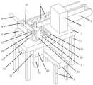
图1为本发明提出的一种智能化的电力设备质量检测设备的正面轴测结构示意图;1 is a schematic diagram of the front axonometric structure of a kind of intelligent power equipment quality detection equipment proposed by the present invention;
图2为本发明提出的一种智能化的电力设备质量检测设备的背面轴测结构示意图;Fig. 2 is a schematic diagram of the rear axonometric structure of an intelligent power equipment quality detection device proposed by the present invention;
图3为本发明提出的一种智能化的电力设备质量检测设备的正面剖切轴测结构示意图;3 is a schematic diagram of a frontal section axonometric structure of an intelligent power equipment quality testing device proposed by the present invention;
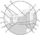
图4为本发明中提出的图3中A区的局部放大结构示意图;Fig. 4 is the partial enlarged structural schematic diagram of A area in Fig. 3 proposed in the present invention;
图5为本发明提出的一种智能化的电力设备质量检测设备的侧面剖切轴测结构示意图。FIG. 5 is a schematic diagram of a side cut axonometric structure of an intelligent power equipment quality detection device proposed by the present invention.
图中:1继电器保护测试仪、2工作台板、3进料传送带、4出料传送带、5继电器、6接线孔、7支撑腿、8L型支撑架、9送料气缸、10L型送料架、11L型固定架、12固定板、13顶紧气缸、14顶紧板、15A绝缘套、16滑动板、17B绝缘套、18尖头导电柱、19升降孔、20L型排料架、21升降板、22升降气缸、23U型卡扣、24挡板、25燕尾导向条、26L型下压架、27下压气缸、28下压片、29L型安装架、30伸缩气缸、31支撑板、32推料板、33推料气缸。In the picture: 1 relay protection tester, 2 worktable, 3 feeding conveyor belt, 4 feeding conveyor belt, 5 relay, 6 wiring holes, 7 supporting legs, 8L type supporting frame, 9 feeding cylinder, 10L type feeding frame, 11L Type fixing frame, 12 fixing plate, 13 top tightening cylinder, 14 top tightening plate, 15A insulating sleeve, 16 sliding plate, 17B insulating sleeve, 18 pointed conductive column, 19 lifting hole, 20L type discharge frame, 21 lifting plate, 22 lift cylinder, 23U type buckle, 24 baffle plate, 25 dovetail guide strip, 26L type lower pressing frame, 27 lower pressing cylinder, 28 lower pressing plate, 29L type mounting frame, 30 telescopic cylinder, 31 supporting plate, 32 pushing material plate, 33 pushing cylinders.
具体实施方式Detailed ways
下面将结合本发明实施例中的附图,对本发明实施例中的技术方案进行清楚、完整地描述,显然,所描述的实施例仅仅是本发明一部分实施例,而不是全部的实施例。The technical solutions in the embodiments of the present invention will be clearly and completely described below with reference to the accompanying drawings in the embodiments of the present invention. Obviously, the described embodiments are only a part of the embodiments of the present invention, but not all of the embodiments.
参照图1-5,一种智能化的电力设备质量检测设备,包括继电器保护测试仪1,继电器保护测试仪1一侧固定设有工作台板2,工作台板2一侧固定设有进料传送带3,工作台板2一侧设有出料传送带4,工作台板2一侧设有继电器5,进料传送带3一侧设有若干继电器5,继电器5包括若干接线孔6,工作台板2一侧固定设有若干支撑腿6,工作台板2一侧固定设有L型支撑架8,L型支撑架8一侧设有通孔,通孔内侧固定设有送料气缸9,L型支撑架8一侧滑动设有L型送料架10,送料气缸9的轴端固定连接在L型送料架10一侧上,使其具有自动供料功能,工作台板2一侧固定设有L型固定架11,L型固定架11一侧固定设有固定板12,固定板12一侧与L型支撑架8一侧固定连接,固定板12一侧设有安装孔,安装孔内侧固定设有顶紧气缸13,顶紧气缸13的轴端固定设有顶紧板14,顶紧板14一侧与L型固定架11一侧滑动连接,使其具有自动定位功能,L型固定架11一侧设有自动压紧装置,L型固定架11一侧设有若干A绝缘孔,A绝缘孔内侧均固定设有A绝缘套15,工作台板2一侧滑动连接设有滑动板16,滑动板16一侧设有若干B绝缘孔,B绝缘孔内侧均固定设有B绝缘套17,B绝缘套17均可滑动连接在A绝缘套15内侧,B绝缘套17内侧均固定设有与接线孔6相匹配的尖头导电柱18,尖头导电柱18另一端均通过导线与继电器保护测试仪1电性连接,当尖头导电柱18滑动接入接线孔6时,继电器保护测试仪1即可对继电器5进行自动检测,使其具有自动检测功能,无需人工进行接线、拆线,从而具有较高的检测效率,滑动板16一侧设有自动滑动装置,工作台板2一侧设有升降孔19,升降孔19内侧固定设有L型排料架20,L型排料架20一侧滑动设有升降板21,升降板21可滑动连接在升降孔19内侧,L型排料架20一侧设有贯穿孔,贯穿孔内侧固定设有升降气缸22,送料气缸9、顶紧气缸13、升降气缸22均需通过气管外接电磁阀,升降气缸22的轴端固定连接在升降板21一侧上,出料传送带4一侧固定连接在L型排料架20一侧上,L型排料架20一侧设有自动推料装置,使其具有自动排料功能。Referring to Figures 1-5, an intelligent power equipment quality inspection equipment includes a relay protection tester 1, a
具体的,L型支撑架8一侧固定设有U型卡扣23,L型送料架10可滑动连接在U型卡扣23内侧。Specifically, a U-shaped
具体的,进料传送带3一侧固定设有两个挡板24。Specifically, two
具体的,工作台板2一侧固定设有若干燕尾导向条25,滑动板16一侧设有若干燕尾槽,燕尾导向条25均可滑动连接在燕尾槽内侧。Specifically, a number of dovetail guide bars 25 are fixed on one side of the
具体的,自动压紧装置包括L型下压架26,L型下压架26一侧固定连接在L型固定架11一侧上,L型下压架26一侧设有下压孔,下压孔内侧固定设有下压气缸27,下压气缸27需通过气管外接电磁阀,下压气缸27的轴端固定设有下压片28。Specifically, the automatic pressing device includes an L-shaped lower pressing
具体的,自动滑动装置包括L型安装架29,L型安装架29一侧固定连接在L型固定架11一侧上,L型安装架29一侧固定设有若干伸缩气缸30,伸缩气缸30均需通过气管外接电磁阀,伸缩气缸30的轴端均固定连接在滑动板16一侧上。Specifically, the automatic sliding device includes an L-shaped mounting
具体的,自动推料装置包括支撑板31,支撑板31一侧固定连接在L型排料架20一侧上,支撑板31一侧设有隐藏槽,隐藏槽内侧设有推料板32,隐藏槽内一侧设有推料孔,推料孔内侧固定设有推料气缸33,推料气缸33需通过气管外接电磁阀,推料气缸33的轴端固定连接在推料板32一侧上。Specifically, the automatic pushing device includes a
本发明,使用时通过设置进料传送带3、继电器5、L型支撑架8、送料气缸9、L型送料架10,可在送料气缸9缩回在状态启动进料传送带3即可使进料传送带3上的继电器5自动前移,当继电器5前移至合适位置时,可控制送料气缸9伸出,即可自动将继电器5推出,从而具有自动供料功能,且单次只会推出单个继电器5,通过设置L型固定架11、固定板12、顶紧气缸13、顶紧板14,当继电器5被推出到位后,可控制顶紧气缸13伸出,即可将继电器5自动顶紧,且继电器5会被顶紧固定在L型固定架11、L型送料架10、顶紧板14之间,从而完成自动定位,使其具有自动定位功能,通过设置A绝缘套15、滑动板16、B绝缘套17、尖头导电柱18、自动滑动装置,当尖头导电柱18滑动接入接线孔6时,继电器保护测试仪1即可对继电器5进行自动检测,使其具有自动检测功能,无需人工进行接线、拆线,从而具有较高的检测效率,通过设置升降孔19、L型排料架20、升降板21、升降气缸22,当继电器5检测完成后,可控制送料气缸9、顶紧气缸13缩回,然后控制升降气缸22缩回,即可使继电器5自动下降,然后通过设置自动推料装置,即可将继电器5自动推至出料传送带4上,从而具有自动排料功能,且当继电器5不合格时,可控制出料传送带4反向运行,将不合格的继电器5传送至另一边,使其具有自动供料、自动检测、自动排料等功能,具有较高的智能自动化程度,具有较高的检测效率,同时可大大减少人力的消耗。In the present invention, by setting the feeding
以上所述,仅为本发明较佳的具体实施方式,但本发明的保护范围并不局限于此,任何熟悉本技术领域的技术人员在本发明揭露的技术范围内,根据本发明的技术方案及其发明构思加以等同替换或改变,都应涵盖在本发明的保护范围之内。The above description is only a preferred embodiment of the present invention, but the protection scope of the present invention is not limited to this. The equivalent replacement or change of the inventive concept thereof shall be included within the protection scope of the present invention.
Claims (7)
Priority Applications (1)
| Application Number | Priority Date | Filing Date | Title |
|---|---|---|---|
| CN202011054492.4ACN112255477B (en) | 2020-09-29 | 2020-09-29 | Intelligent power equipment quality detection equipment |
Applications Claiming Priority (1)
| Application Number | Priority Date | Filing Date | Title |
|---|---|---|---|
| CN202011054492.4ACN112255477B (en) | 2020-09-29 | 2020-09-29 | Intelligent power equipment quality detection equipment |
Publications (2)
| Publication Number | Publication Date |
|---|---|
| CN112255477A CN112255477A (en) | 2021-01-22 |
| CN112255477Btrue CN112255477B (en) | 2022-07-22 |
Family
ID=74233966
Family Applications (1)
| Application Number | Title | Priority Date | Filing Date |
|---|---|---|---|
| CN202011054492.4AActiveCN112255477B (en) | 2020-09-29 | 2020-09-29 | Intelligent power equipment quality detection equipment |
Country Status (1)
| Country | Link |
|---|---|
| CN (1) | CN112255477B (en) |
Families Citing this family (2)
| Publication number | Priority date | Publication date | Assignee | Title |
|---|---|---|---|---|
| CN113560851B (en)* | 2021-08-12 | 2024-07-05 | 深圳鑫宏力精密工业有限公司 | Assembling equipment and assembling method for assembling mobile phone shell and inlay |
| CN116754974B (en)* | 2023-08-23 | 2023-10-20 | 深圳市拓尔德能源有限公司 | Charging and discharging testing device for lithium battery |
Citations (4)
| Publication number | Priority date | Publication date | Assignee | Title |
|---|---|---|---|---|
| CN103894748A (en)* | 2014-03-20 | 2014-07-02 | 深圳市凯德科技发展有限公司 | Automatic welding machine for relay lead |
| CN107843217A (en)* | 2017-12-22 | 2018-03-27 | 珠海市瑞信精密科技有限公司 | Fin flatness detecting instrument |
| CN109782165A (en)* | 2017-01-03 | 2019-05-21 | 邓君 | A kind of relay detects blanking machine automatically |
| CN211580434U (en)* | 2020-05-06 | 2020-09-25 | 胥锋 | PLC cabinet with classified installation |
Family Cites Families (7)
| Publication number | Priority date | Publication date | Assignee | Title |
|---|---|---|---|---|
| CN203838294U (en)* | 2014-04-30 | 2014-09-17 | 广东格兰仕集团有限公司 | Relay terminal tinning and testing device |
| CN106903077A (en)* | 2017-03-24 | 2017-06-30 | 东莞大市自动化科技有限公司 | A fully automatic product testing method, intelligent equipment and system |
| CN107887230B (en)* | 2017-11-03 | 2019-10-29 | 三友联众集团股份有限公司 | A relay reed insertion mechanism |
| CN107876440B (en)* | 2017-12-12 | 2023-05-09 | 深圳新益昌科技股份有限公司 | Automatic static testing mechanism |
| CN108974740B (en)* | 2018-07-18 | 2020-10-27 | 国网山东省电力公司烟台供电公司 | Movable unloading rack for electric power materials |
| CN211476930U (en)* | 2020-04-23 | 2020-09-11 | 华铝铝业有限公司 | High-efficient anchor clamps among aluminium alloy check out test set |
| CN111505967B (en)* | 2020-05-06 | 2025-01-14 | 中核(天津)科技发展有限公司 | Semi-automatic assembly and testing device control circuit |
- 2020
- 2020-09-29CNCN202011054492.4Apatent/CN112255477B/enactiveActive
Patent Citations (4)
| Publication number | Priority date | Publication date | Assignee | Title |
|---|---|---|---|---|
| CN103894748A (en)* | 2014-03-20 | 2014-07-02 | 深圳市凯德科技发展有限公司 | Automatic welding machine for relay lead |
| CN109782165A (en)* | 2017-01-03 | 2019-05-21 | 邓君 | A kind of relay detects blanking machine automatically |
| CN107843217A (en)* | 2017-12-22 | 2018-03-27 | 珠海市瑞信精密科技有限公司 | Fin flatness detecting instrument |
| CN211580434U (en)* | 2020-05-06 | 2020-09-25 | 胥锋 | PLC cabinet with classified installation |
Also Published As
| Publication number | Publication date |
|---|---|
| CN112255477A (en) | 2021-01-22 |
Similar Documents
| Publication | Publication Date | Title |
|---|---|---|
| CN112255477B (en) | Intelligent power equipment quality detection equipment | |
| CN106141398B (en) | Breaker contact system process equipment | |
| CN105353324A (en) | LED lamp bead detection device | |
| CN108169523B (en) | Plate passing mechanism for online test | |
| CN107275878B (en) | The fast plug device of robot electricity | |
| CN211402608U (en) | Withstand voltage test fixture of iron core class | |
| CN211826356U (en) | Three-phase five-wire system leakage current test fixture | |
| CN212576908U (en) | Automatic shell fragment of controller clamps power tube and insulation test equipment | |
| CN211554296U (en) | Universal positioning and crimping device for electric energy meter | |
| CN114334552A (en) | Square fuse automatic assembly machine and square fuse automatic assembly method | |
| CN209198599U (en) | A kind of Chinese watt insulation resistance test equipment | |
| CN208172184U (en) | Unified test equipment for fan wiring board | |
| CN223320182U (en) | Semi-automatic detection two-in-one equipment | |
| CN208705418U (en) | A kind of welded type filter degradation tooling | |
| CN204639410U (en) | Breaker contact system welder | |
| CN223107693U (en) | A testing equipment for heating tube production | |
| CN217542684U (en) | A intensity detection device for circuit board processing | |
| CN112881898A (en) | High-temperature aging test device for integrated circuit | |
| CN220795388U (en) | Sealed vacuum type high-voltage testing device for electric power products | |
| CN212208042U (en) | Sterilizing knife rest controller testing device based on UVC light wave and PTC heating | |
| CN222471243U (en) | High-voltage internal resistance detector for new energy cover plate | |
| CN221550852U (en) | Detection jig for circuit board | |
| CN213023207U (en) | A test tool for switching power supply PCB board | |
| CN205749679U (en) | Many specifications insulating bar universal test support | |
| CN216310157U (en) | Conduction testing mechanism |
Legal Events
| Date | Code | Title | Description |
|---|---|---|---|
| PB01 | Publication | ||
| PB01 | Publication | ||
| SE01 | Entry into force of request for substantive examination | ||
| SE01 | Entry into force of request for substantive examination | ||
| TA01 | Transfer of patent application right | Effective date of registration:20210531 Address after:264000 Jiefang Road 158, Zhifu District, Yantai, Shandong Applicant after:State Grid Shandong Electric Power Company Yantai Power Supply Co. Address before:264000 Jiefang Road 158, Zhifu District, Yantai, Shandong Applicant before:State Grid Shandong Electric Power Company Yantai Power Supply Co. Applicant before:STATE GRID CORPORATION OF CHINA | |
| TA01 | Transfer of patent application right | ||
| GR01 | Patent grant | ||
| GR01 | Patent grant |