CN112237659B - Miniature full-closed-loop artificial pancreas system - Google Patents
Miniature full-closed-loop artificial pancreas systemDownload PDFInfo
- Publication number
- CN112237659B CN112237659BCN201911421196.0ACN201911421196ACN112237659BCN 112237659 BCN112237659 BCN 112237659BCN 201911421196 ACN201911421196 ACN 201911421196ACN 112237659 BCN112237659 BCN 112237659B
- Authority
- CN
- China
- Prior art keywords
- infusion
- electrode
- unit
- tube
- artificial pancreas
- Prior art date
- Legal status (The legal status is an assumption and is not a legal conclusion. Google has not performed a legal analysis and makes no representation as to the accuracy of the status listed.)
- Active
Links
Images


Classifications
- A—HUMAN NECESSITIES
- A61—MEDICAL OR VETERINARY SCIENCE; HYGIENE
- A61M—DEVICES FOR INTRODUCING MEDIA INTO, OR ONTO, THE BODY; DEVICES FOR TRANSDUCING BODY MEDIA OR FOR TAKING MEDIA FROM THE BODY; DEVICES FOR PRODUCING OR ENDING SLEEP OR STUPOR
- A61M5/00—Devices for bringing media into the body in a subcutaneous, intra-vascular or intramuscular way; Accessories therefor, e.g. filling or cleaning devices, arm-rests
- A61M5/14—Infusion devices, e.g. infusing by gravity; Blood infusion; Accessories therefor
- A61M5/168—Means for controlling media flow to the body or for metering media to the body, e.g. drip meters, counters ; Monitoring media flow to the body
- A61M5/16804—Flow controllers
- A—HUMAN NECESSITIES
- A61—MEDICAL OR VETERINARY SCIENCE; HYGIENE
- A61M—DEVICES FOR INTRODUCING MEDIA INTO, OR ONTO, THE BODY; DEVICES FOR TRANSDUCING BODY MEDIA OR FOR TAKING MEDIA FROM THE BODY; DEVICES FOR PRODUCING OR ENDING SLEEP OR STUPOR
- A61M5/00—Devices for bringing media into the body in a subcutaneous, intra-vascular or intramuscular way; Accessories therefor, e.g. filling or cleaning devices, arm-rests
- A61M5/14—Infusion devices, e.g. infusing by gravity; Blood infusion; Accessories therefor
- A61M5/142—Pressure infusion, e.g. using pumps
- A61M5/145—Pressure infusion, e.g. using pumps using pressurised reservoirs, e.g. pressurised by means of pistons
- A—HUMAN NECESSITIES
- A61—MEDICAL OR VETERINARY SCIENCE; HYGIENE
- A61B—DIAGNOSIS; SURGERY; IDENTIFICATION
- A61B5/00—Measuring for diagnostic purposes; Identification of persons
- A61B5/145—Measuring characteristics of blood in vivo, e.g. gas concentration or pH-value ; Measuring characteristics of body fluids or tissues, e.g. interstitial fluid or cerebral tissue
- A61B5/14532—Measuring characteristics of blood in vivo, e.g. gas concentration or pH-value ; Measuring characteristics of body fluids or tissues, e.g. interstitial fluid or cerebral tissue for measuring glucose, e.g. by tissue impedance measurement
- A—HUMAN NECESSITIES
- A61—MEDICAL OR VETERINARY SCIENCE; HYGIENE
- A61B—DIAGNOSIS; SURGERY; IDENTIFICATION
- A61B5/00—Measuring for diagnostic purposes; Identification of persons
- A61B5/145—Measuring characteristics of blood in vivo, e.g. gas concentration or pH-value ; Measuring characteristics of body fluids or tissues, e.g. interstitial fluid or cerebral tissue
- A61B5/1468—Measuring characteristics of blood in vivo, e.g. gas concentration or pH-value ; Measuring characteristics of body fluids or tissues, e.g. interstitial fluid or cerebral tissue using chemical or electrochemical methods, e.g. by polarographic means
- A61B5/1473—Measuring characteristics of blood in vivo, e.g. gas concentration or pH-value ; Measuring characteristics of body fluids or tissues, e.g. interstitial fluid or cerebral tissue using chemical or electrochemical methods, e.g. by polarographic means invasive, e.g. introduced into the body by a catheter
- A—HUMAN NECESSITIES
- A61—MEDICAL OR VETERINARY SCIENCE; HYGIENE
- A61B—DIAGNOSIS; SURGERY; IDENTIFICATION
- A61B5/00—Measuring for diagnostic purposes; Identification of persons
- A61B5/48—Other medical applications
- A61B5/4836—Diagnosis combined with treatment in closed-loop systems or methods
- A61B5/4839—Diagnosis combined with treatment in closed-loop systems or methods combined with drug delivery
- A—HUMAN NECESSITIES
- A61—MEDICAL OR VETERINARY SCIENCE; HYGIENE
- A61F—FILTERS IMPLANTABLE INTO BLOOD VESSELS; PROSTHESES; DEVICES PROVIDING PATENCY TO, OR PREVENTING COLLAPSING OF, TUBULAR STRUCTURES OF THE BODY, e.g. STENTS; ORTHOPAEDIC, NURSING OR CONTRACEPTIVE DEVICES; FOMENTATION; TREATMENT OR PROTECTION OF EYES OR EARS; BANDAGES, DRESSINGS OR ABSORBENT PADS; FIRST-AID KITS
- A61F2/00—Filters implantable into blood vessels; Prostheses, i.e. artificial substitutes or replacements for parts of the body; Appliances for connecting them with the body; Devices providing patency to, or preventing collapsing of, tubular structures of the body, e.g. stents
- A61F2/02—Prostheses implantable into the body
- A61F2/022—Artificial gland structures using bioreactors
- A—HUMAN NECESSITIES
- A61—MEDICAL OR VETERINARY SCIENCE; HYGIENE
- A61M—DEVICES FOR INTRODUCING MEDIA INTO, OR ONTO, THE BODY; DEVICES FOR TRANSDUCING BODY MEDIA OR FOR TAKING MEDIA FROM THE BODY; DEVICES FOR PRODUCING OR ENDING SLEEP OR STUPOR
- A61M5/00—Devices for bringing media into the body in a subcutaneous, intra-vascular or intramuscular way; Accessories therefor, e.g. filling or cleaning devices, arm-rests
- A61M5/14—Infusion devices, e.g. infusing by gravity; Blood infusion; Accessories therefor
- A61M5/142—Pressure infusion, e.g. using pumps
- A61M5/14212—Pumping with an aspiration and an expulsion action
- A61M5/14236—Screw, impeller or centrifugal type pumps
- A—HUMAN NECESSITIES
- A61—MEDICAL OR VETERINARY SCIENCE; HYGIENE
- A61M—DEVICES FOR INTRODUCING MEDIA INTO, OR ONTO, THE BODY; DEVICES FOR TRANSDUCING BODY MEDIA OR FOR TAKING MEDIA FROM THE BODY; DEVICES FOR PRODUCING OR ENDING SLEEP OR STUPOR
- A61M5/00—Devices for bringing media into the body in a subcutaneous, intra-vascular or intramuscular way; Accessories therefor, e.g. filling or cleaning devices, arm-rests
- A61M5/14—Infusion devices, e.g. infusing by gravity; Blood infusion; Accessories therefor
- A61M5/142—Pressure infusion, e.g. using pumps
- A61M5/14244—Pressure infusion, e.g. using pumps adapted to be carried by the patient, e.g. portable on the body
- A61M5/14248—Pressure infusion, e.g. using pumps adapted to be carried by the patient, e.g. portable on the body of the skin patch type
- A—HUMAN NECESSITIES
- A61—MEDICAL OR VETERINARY SCIENCE; HYGIENE
- A61M—DEVICES FOR INTRODUCING MEDIA INTO, OR ONTO, THE BODY; DEVICES FOR TRANSDUCING BODY MEDIA OR FOR TAKING MEDIA FROM THE BODY; DEVICES FOR PRODUCING OR ENDING SLEEP OR STUPOR
- A61M5/00—Devices for bringing media into the body in a subcutaneous, intra-vascular or intramuscular way; Accessories therefor, e.g. filling or cleaning devices, arm-rests
- A61M5/14—Infusion devices, e.g. infusing by gravity; Blood infusion; Accessories therefor
- A61M5/142—Pressure infusion, e.g. using pumps
- A61M5/145—Pressure infusion, e.g. using pumps using pressurised reservoirs, e.g. pressurised by means of pistons
- A61M5/1452—Pressure infusion, e.g. using pumps using pressurised reservoirs, e.g. pressurised by means of pistons pressurised by means of pistons
- A61M5/1454—Pressure infusion, e.g. using pumps using pressurised reservoirs, e.g. pressurised by means of pistons pressurised by means of pistons spring-actuated, e.g. by a clockwork
- A—HUMAN NECESSITIES
- A61—MEDICAL OR VETERINARY SCIENCE; HYGIENE
- A61M—DEVICES FOR INTRODUCING MEDIA INTO, OR ONTO, THE BODY; DEVICES FOR TRANSDUCING BODY MEDIA OR FOR TAKING MEDIA FROM THE BODY; DEVICES FOR PRODUCING OR ENDING SLEEP OR STUPOR
- A61M5/00—Devices for bringing media into the body in a subcutaneous, intra-vascular or intramuscular way; Accessories therefor, e.g. filling or cleaning devices, arm-rests
- A61M5/14—Infusion devices, e.g. infusing by gravity; Blood infusion; Accessories therefor
- A61M5/158—Needles for infusions; Accessories therefor, e.g. for inserting infusion needles, or for holding them on the body
- A—HUMAN NECESSITIES
- A61—MEDICAL OR VETERINARY SCIENCE; HYGIENE
- A61M—DEVICES FOR INTRODUCING MEDIA INTO, OR ONTO, THE BODY; DEVICES FOR TRANSDUCING BODY MEDIA OR FOR TAKING MEDIA FROM THE BODY; DEVICES FOR PRODUCING OR ENDING SLEEP OR STUPOR
- A61M5/00—Devices for bringing media into the body in a subcutaneous, intra-vascular or intramuscular way; Accessories therefor, e.g. filling or cleaning devices, arm-rests
- A61M5/14—Infusion devices, e.g. infusing by gravity; Blood infusion; Accessories therefor
- A61M5/168—Means for controlling media flow to the body or for metering media to the body, e.g. drip meters, counters ; Monitoring media flow to the body
- A61M5/172—Means for controlling media flow to the body or for metering media to the body, e.g. drip meters, counters ; Monitoring media flow to the body electrical or electronic
- A—HUMAN NECESSITIES
- A61—MEDICAL OR VETERINARY SCIENCE; HYGIENE
- A61M—DEVICES FOR INTRODUCING MEDIA INTO, OR ONTO, THE BODY; DEVICES FOR TRANSDUCING BODY MEDIA OR FOR TAKING MEDIA FROM THE BODY; DEVICES FOR PRODUCING OR ENDING SLEEP OR STUPOR
- A61M5/00—Devices for bringing media into the body in a subcutaneous, intra-vascular or intramuscular way; Accessories therefor, e.g. filling or cleaning devices, arm-rests
- A61M5/178—Syringes
- A61M5/20—Automatic syringes, e.g. with automatically actuated piston rod, with automatic needle injection, filling automatically
- A—HUMAN NECESSITIES
- A61—MEDICAL OR VETERINARY SCIENCE; HYGIENE
- A61M—DEVICES FOR INTRODUCING MEDIA INTO, OR ONTO, THE BODY; DEVICES FOR TRANSDUCING BODY MEDIA OR FOR TAKING MEDIA FROM THE BODY; DEVICES FOR PRODUCING OR ENDING SLEEP OR STUPOR
- A61M5/00—Devices for bringing media into the body in a subcutaneous, intra-vascular or intramuscular way; Accessories therefor, e.g. filling or cleaning devices, arm-rests
- A61M5/178—Syringes
- A61M5/31—Details
- G—PHYSICS
- G16—INFORMATION AND COMMUNICATION TECHNOLOGY [ICT] SPECIALLY ADAPTED FOR SPECIFIC APPLICATION FIELDS
- G16H—HEALTHCARE INFORMATICS, i.e. INFORMATION AND COMMUNICATION TECHNOLOGY [ICT] SPECIALLY ADAPTED FOR THE HANDLING OR PROCESSING OF MEDICAL OR HEALTHCARE DATA
- G16H20/00—ICT specially adapted for therapies or health-improving plans, e.g. for handling prescriptions, for steering therapy or for monitoring patient compliance
- G16H20/10—ICT specially adapted for therapies or health-improving plans, e.g. for handling prescriptions, for steering therapy or for monitoring patient compliance relating to drugs or medications, e.g. for ensuring correct administration to patients
- G16H20/17—ICT specially adapted for therapies or health-improving plans, e.g. for handling prescriptions, for steering therapy or for monitoring patient compliance relating to drugs or medications, e.g. for ensuring correct administration to patients delivered via infusion or injection
- G—PHYSICS
- G16—INFORMATION AND COMMUNICATION TECHNOLOGY [ICT] SPECIALLY ADAPTED FOR SPECIFIC APPLICATION FIELDS
- G16H—HEALTHCARE INFORMATICS, i.e. INFORMATION AND COMMUNICATION TECHNOLOGY [ICT] SPECIALLY ADAPTED FOR THE HANDLING OR PROCESSING OF MEDICAL OR HEALTHCARE DATA
- G16H40/00—ICT specially adapted for the management or administration of healthcare resources or facilities; ICT specially adapted for the management or operation of medical equipment or devices
- G16H40/60—ICT specially adapted for the management or administration of healthcare resources or facilities; ICT specially adapted for the management or operation of medical equipment or devices for the operation of medical equipment or devices
- G16H40/63—ICT specially adapted for the management or administration of healthcare resources or facilities; ICT specially adapted for the management or operation of medical equipment or devices for the operation of medical equipment or devices for local operation
- A—HUMAN NECESSITIES
- A61—MEDICAL OR VETERINARY SCIENCE; HYGIENE
- A61B—DIAGNOSIS; SURGERY; IDENTIFICATION
- A61B2560/00—Constructional details of operational features of apparatus; Accessories for medical measuring apparatus
- A61B2560/02—Operational features
- A61B2560/0204—Operational features of power management
- A61B2560/0209—Operational features of power management adapted for power saving
- A—HUMAN NECESSITIES
- A61—MEDICAL OR VETERINARY SCIENCE; HYGIENE
- A61B—DIAGNOSIS; SURGERY; IDENTIFICATION
- A61B2562/00—Details of sensors; Constructional details of sensor housings or probes; Accessories for sensors
- A61B2562/04—Arrangements of multiple sensors of the same type
- A61B2562/043—Arrangements of multiple sensors of the same type in a linear array
- A—HUMAN NECESSITIES
- A61—MEDICAL OR VETERINARY SCIENCE; HYGIENE
- A61M—DEVICES FOR INTRODUCING MEDIA INTO, OR ONTO, THE BODY; DEVICES FOR TRANSDUCING BODY MEDIA OR FOR TAKING MEDIA FROM THE BODY; DEVICES FOR PRODUCING OR ENDING SLEEP OR STUPOR
- A61M5/00—Devices for bringing media into the body in a subcutaneous, intra-vascular or intramuscular way; Accessories therefor, e.g. filling or cleaning devices, arm-rests
- A61M5/14—Infusion devices, e.g. infusing by gravity; Blood infusion; Accessories therefor
- A61M5/142—Pressure infusion, e.g. using pumps
- A61M2005/14208—Pressure infusion, e.g. using pumps with a programmable infusion control system, characterised by the infusion program
- A—HUMAN NECESSITIES
- A61—MEDICAL OR VETERINARY SCIENCE; HYGIENE
- A61M—DEVICES FOR INTRODUCING MEDIA INTO, OR ONTO, THE BODY; DEVICES FOR TRANSDUCING BODY MEDIA OR FOR TAKING MEDIA FROM THE BODY; DEVICES FOR PRODUCING OR ENDING SLEEP OR STUPOR
- A61M5/00—Devices for bringing media into the body in a subcutaneous, intra-vascular or intramuscular way; Accessories therefor, e.g. filling or cleaning devices, arm-rests
- A61M5/14—Infusion devices, e.g. infusing by gravity; Blood infusion; Accessories therefor
- A61M5/142—Pressure infusion, e.g. using pumps
- A61M5/14244—Pressure infusion, e.g. using pumps adapted to be carried by the patient, e.g. portable on the body
- A61M5/14248—Pressure infusion, e.g. using pumps adapted to be carried by the patient, e.g. portable on the body of the skin patch type
- A61M2005/14252—Pressure infusion, e.g. using pumps adapted to be carried by the patient, e.g. portable on the body of the skin patch type with needle insertion means
- A—HUMAN NECESSITIES
- A61—MEDICAL OR VETERINARY SCIENCE; HYGIENE
- A61M—DEVICES FOR INTRODUCING MEDIA INTO, OR ONTO, THE BODY; DEVICES FOR TRANSDUCING BODY MEDIA OR FOR TAKING MEDIA FROM THE BODY; DEVICES FOR PRODUCING OR ENDING SLEEP OR STUPOR
- A61M5/00—Devices for bringing media into the body in a subcutaneous, intra-vascular or intramuscular way; Accessories therefor, e.g. filling or cleaning devices, arm-rests
- A61M5/14—Infusion devices, e.g. infusing by gravity; Blood infusion; Accessories therefor
- A61M5/142—Pressure infusion, e.g. using pumps
- A61M5/14244—Pressure infusion, e.g. using pumps adapted to be carried by the patient, e.g. portable on the body
- A61M2005/14268—Pressure infusion, e.g. using pumps adapted to be carried by the patient, e.g. portable on the body with a reusable and a disposable component
- A—HUMAN NECESSITIES
- A61—MEDICAL OR VETERINARY SCIENCE; HYGIENE
- A61M—DEVICES FOR INTRODUCING MEDIA INTO, OR ONTO, THE BODY; DEVICES FOR TRANSDUCING BODY MEDIA OR FOR TAKING MEDIA FROM THE BODY; DEVICES FOR PRODUCING OR ENDING SLEEP OR STUPOR
- A61M5/00—Devices for bringing media into the body in a subcutaneous, intra-vascular or intramuscular way; Accessories therefor, e.g. filling or cleaning devices, arm-rests
- A61M5/14—Infusion devices, e.g. infusing by gravity; Blood infusion; Accessories therefor
- A61M5/142—Pressure infusion, e.g. using pumps
- A61M5/145—Pressure infusion, e.g. using pumps using pressurised reservoirs, e.g. pressurised by means of pistons
- A61M2005/14506—Pressure infusion, e.g. using pumps using pressurised reservoirs, e.g. pressurised by means of pistons mechanically driven, e.g. spring or clockwork
- A—HUMAN NECESSITIES
- A61—MEDICAL OR VETERINARY SCIENCE; HYGIENE
- A61M—DEVICES FOR INTRODUCING MEDIA INTO, OR ONTO, THE BODY; DEVICES FOR TRANSDUCING BODY MEDIA OR FOR TAKING MEDIA FROM THE BODY; DEVICES FOR PRODUCING OR ENDING SLEEP OR STUPOR
- A61M5/00—Devices for bringing media into the body in a subcutaneous, intra-vascular or intramuscular way; Accessories therefor, e.g. filling or cleaning devices, arm-rests
- A61M5/14—Infusion devices, e.g. infusing by gravity; Blood infusion; Accessories therefor
- A61M5/158—Needles for infusions; Accessories therefor, e.g. for inserting infusion needles, or for holding them on the body
- A61M2005/1585—Needle inserters
- A—HUMAN NECESSITIES
- A61—MEDICAL OR VETERINARY SCIENCE; HYGIENE
- A61M—DEVICES FOR INTRODUCING MEDIA INTO, OR ONTO, THE BODY; DEVICES FOR TRANSDUCING BODY MEDIA OR FOR TAKING MEDIA FROM THE BODY; DEVICES FOR PRODUCING OR ENDING SLEEP OR STUPOR
- A61M5/00—Devices for bringing media into the body in a subcutaneous, intra-vascular or intramuscular way; Accessories therefor, e.g. filling or cleaning devices, arm-rests
- A61M5/14—Infusion devices, e.g. infusing by gravity; Blood infusion; Accessories therefor
- A61M5/168—Means for controlling media flow to the body or for metering media to the body, e.g. drip meters, counters ; Monitoring media flow to the body
- A61M5/172—Means for controlling media flow to the body or for metering media to the body, e.g. drip meters, counters ; Monitoring media flow to the body electrical or electronic
- A61M5/1723—Means for controlling media flow to the body or for metering media to the body, e.g. drip meters, counters ; Monitoring media flow to the body electrical or electronic using feedback of body parameters, e.g. blood-sugar, pressure
- A61M2005/1726—Means for controlling media flow to the body or for metering media to the body, e.g. drip meters, counters ; Monitoring media flow to the body electrical or electronic using feedback of body parameters, e.g. blood-sugar, pressure the body parameters being measured at, or proximate to, the infusion site
- A—HUMAN NECESSITIES
- A61—MEDICAL OR VETERINARY SCIENCE; HYGIENE
- A61M—DEVICES FOR INTRODUCING MEDIA INTO, OR ONTO, THE BODY; DEVICES FOR TRANSDUCING BODY MEDIA OR FOR TAKING MEDIA FROM THE BODY; DEVICES FOR PRODUCING OR ENDING SLEEP OR STUPOR
- A61M5/00—Devices for bringing media into the body in a subcutaneous, intra-vascular or intramuscular way; Accessories therefor, e.g. filling or cleaning devices, arm-rests
- A61M5/178—Syringes
- A61M5/20—Automatic syringes, e.g. with automatically actuated piston rod, with automatic needle injection, filling automatically
- A61M2005/2006—Having specific accessories
- A—HUMAN NECESSITIES
- A61—MEDICAL OR VETERINARY SCIENCE; HYGIENE
- A61M—DEVICES FOR INTRODUCING MEDIA INTO, OR ONTO, THE BODY; DEVICES FOR TRANSDUCING BODY MEDIA OR FOR TAKING MEDIA FROM THE BODY; DEVICES FOR PRODUCING OR ENDING SLEEP OR STUPOR
- A61M2205/00—General characteristics of the apparatus
- A61M2205/02—General characteristics of the apparatus characterised by a particular materials
- A61M2205/0216—Materials providing elastic properties, e.g. for facilitating deformation and avoid breaking
- A—HUMAN NECESSITIES
- A61—MEDICAL OR VETERINARY SCIENCE; HYGIENE
- A61M—DEVICES FOR INTRODUCING MEDIA INTO, OR ONTO, THE BODY; DEVICES FOR TRANSDUCING BODY MEDIA OR FOR TAKING MEDIA FROM THE BODY; DEVICES FOR PRODUCING OR ENDING SLEEP OR STUPOR
- A61M2205/00—General characteristics of the apparatus
- A61M2205/02—General characteristics of the apparatus characterised by a particular materials
- A61M2205/0233—Conductive materials, e.g. antistatic coatings for spark prevention
- A—HUMAN NECESSITIES
- A61—MEDICAL OR VETERINARY SCIENCE; HYGIENE
- A61M—DEVICES FOR INTRODUCING MEDIA INTO, OR ONTO, THE BODY; DEVICES FOR TRANSDUCING BODY MEDIA OR FOR TAKING MEDIA FROM THE BODY; DEVICES FOR PRODUCING OR ENDING SLEEP OR STUPOR
- A61M2205/00—General characteristics of the apparatus
- A61M2205/02—General characteristics of the apparatus characterised by a particular materials
- A61M2205/0266—Shape memory materials
- A—HUMAN NECESSITIES
- A61—MEDICAL OR VETERINARY SCIENCE; HYGIENE
- A61M—DEVICES FOR INTRODUCING MEDIA INTO, OR ONTO, THE BODY; DEVICES FOR TRANSDUCING BODY MEDIA OR FOR TAKING MEDIA FROM THE BODY; DEVICES FOR PRODUCING OR ENDING SLEEP OR STUPOR
- A61M2205/00—General characteristics of the apparatus
- A61M2205/33—Controlling, regulating or measuring
- A61M2205/3317—Electromagnetic, inductive or dielectric measuring means
- A—HUMAN NECESSITIES
- A61—MEDICAL OR VETERINARY SCIENCE; HYGIENE
- A61M—DEVICES FOR INTRODUCING MEDIA INTO, OR ONTO, THE BODY; DEVICES FOR TRANSDUCING BODY MEDIA OR FOR TAKING MEDIA FROM THE BODY; DEVICES FOR PRODUCING OR ENDING SLEEP OR STUPOR
- A61M2205/00—General characteristics of the apparatus
- A61M2205/33—Controlling, regulating or measuring
- A61M2205/3327—Measuring
- A—HUMAN NECESSITIES
- A61—MEDICAL OR VETERINARY SCIENCE; HYGIENE
- A61M—DEVICES FOR INTRODUCING MEDIA INTO, OR ONTO, THE BODY; DEVICES FOR TRANSDUCING BODY MEDIA OR FOR TAKING MEDIA FROM THE BODY; DEVICES FOR PRODUCING OR ENDING SLEEP OR STUPOR
- A61M2205/00—General characteristics of the apparatus
- A61M2205/35—Communication
- A61M2205/3546—Range
- A61M2205/3553—Range remote, e.g. between patient's home and doctor's office
- A—HUMAN NECESSITIES
- A61—MEDICAL OR VETERINARY SCIENCE; HYGIENE
- A61M—DEVICES FOR INTRODUCING MEDIA INTO, OR ONTO, THE BODY; DEVICES FOR TRANSDUCING BODY MEDIA OR FOR TAKING MEDIA FROM THE BODY; DEVICES FOR PRODUCING OR ENDING SLEEP OR STUPOR
- A61M2205/00—General characteristics of the apparatus
- A61M2205/35—Communication
- A61M2205/3576—Communication with non implanted data transmission devices, e.g. using external transmitter or receiver
- A61M2205/3592—Communication with non implanted data transmission devices, e.g. using external transmitter or receiver using telemetric means, e.g. radio or optical transmission
- A—HUMAN NECESSITIES
- A61—MEDICAL OR VETERINARY SCIENCE; HYGIENE
- A61M—DEVICES FOR INTRODUCING MEDIA INTO, OR ONTO, THE BODY; DEVICES FOR TRANSDUCING BODY MEDIA OR FOR TAKING MEDIA FROM THE BODY; DEVICES FOR PRODUCING OR ENDING SLEEP OR STUPOR
- A61M2205/00—General characteristics of the apparatus
- A61M2205/50—General characteristics of the apparatus with microprocessors or computers
- A61M2205/502—User interfaces, e.g. screens or keyboards
- A—HUMAN NECESSITIES
- A61—MEDICAL OR VETERINARY SCIENCE; HYGIENE
- A61M—DEVICES FOR INTRODUCING MEDIA INTO, OR ONTO, THE BODY; DEVICES FOR TRANSDUCING BODY MEDIA OR FOR TAKING MEDIA FROM THE BODY; DEVICES FOR PRODUCING OR ENDING SLEEP OR STUPOR
- A61M2209/00—Ancillary equipment
- A61M2209/08—Supports for equipment
- A61M2209/088—Supports for equipment on the body
- A—HUMAN NECESSITIES
- A61—MEDICAL OR VETERINARY SCIENCE; HYGIENE
- A61M—DEVICES FOR INTRODUCING MEDIA INTO, OR ONTO, THE BODY; DEVICES FOR TRANSDUCING BODY MEDIA OR FOR TAKING MEDIA FROM THE BODY; DEVICES FOR PRODUCING OR ENDING SLEEP OR STUPOR
- A61M2230/00—Measuring parameters of the user
- A61M2230/005—Parameter used as control input for the apparatus
- A—HUMAN NECESSITIES
- A61—MEDICAL OR VETERINARY SCIENCE; HYGIENE
- A61M—DEVICES FOR INTRODUCING MEDIA INTO, OR ONTO, THE BODY; DEVICES FOR TRANSDUCING BODY MEDIA OR FOR TAKING MEDIA FROM THE BODY; DEVICES FOR PRODUCING OR ENDING SLEEP OR STUPOR
- A61M2230/00—Measuring parameters of the user
- A61M2230/20—Blood composition characteristics
- A61M2230/201—Glucose concentration
- A—HUMAN NECESSITIES
- A61—MEDICAL OR VETERINARY SCIENCE; HYGIENE
- A61M—DEVICES FOR INTRODUCING MEDIA INTO, OR ONTO, THE BODY; DEVICES FOR TRANSDUCING BODY MEDIA OR FOR TAKING MEDIA FROM THE BODY; DEVICES FOR PRODUCING OR ENDING SLEEP OR STUPOR
- A61M5/00—Devices for bringing media into the body in a subcutaneous, intra-vascular or intramuscular way; Accessories therefor, e.g. filling or cleaning devices, arm-rests
- A61M5/14—Infusion devices, e.g. infusing by gravity; Blood infusion; Accessories therefor
- A61M5/1413—Modular systems comprising interconnecting elements
- A—HUMAN NECESSITIES
- A61—MEDICAL OR VETERINARY SCIENCE; HYGIENE
- A61M—DEVICES FOR INTRODUCING MEDIA INTO, OR ONTO, THE BODY; DEVICES FOR TRANSDUCING BODY MEDIA OR FOR TAKING MEDIA FROM THE BODY; DEVICES FOR PRODUCING OR ENDING SLEEP OR STUPOR
- A61M5/00—Devices for bringing media into the body in a subcutaneous, intra-vascular or intramuscular way; Accessories therefor, e.g. filling or cleaning devices, arm-rests
- A61M5/14—Infusion devices, e.g. infusing by gravity; Blood infusion; Accessories therefor
- A61M5/168—Means for controlling media flow to the body or for metering media to the body, e.g. drip meters, counters ; Monitoring media flow to the body
- A61M5/172—Means for controlling media flow to the body or for metering media to the body, e.g. drip meters, counters ; Monitoring media flow to the body electrical or electronic
- A61M5/1723—Means for controlling media flow to the body or for metering media to the body, e.g. drip meters, counters ; Monitoring media flow to the body electrical or electronic using feedback of body parameters, e.g. blood-sugar, pressure
Landscapes
- Health & Medical Sciences (AREA)
- Life Sciences & Earth Sciences (AREA)
- Engineering & Computer Science (AREA)
- Biomedical Technology (AREA)
- Public Health (AREA)
- General Health & Medical Sciences (AREA)
- Animal Behavior & Ethology (AREA)
- Heart & Thoracic Surgery (AREA)
- Veterinary Medicine (AREA)
- Vascular Medicine (AREA)
- Physics & Mathematics (AREA)
- Hematology (AREA)
- Anesthesiology (AREA)
- Medical Informatics (AREA)
- Surgery (AREA)
- Molecular Biology (AREA)
- Pathology (AREA)
- Biophysics (AREA)
- Optics & Photonics (AREA)
- Chemical & Material Sciences (AREA)
- Bioinformatics & Cheminformatics (AREA)
- Medicinal Chemistry (AREA)
- Chemical Kinetics & Catalysis (AREA)
- Emergency Medicine (AREA)
- General Chemical & Material Sciences (AREA)
- Primary Health Care (AREA)
- Epidemiology (AREA)
- Transplantation (AREA)
- Dermatology (AREA)
- Pharmacology & Pharmacy (AREA)
- Diabetes (AREA)
- General Business, Economics & Management (AREA)
- Business, Economics & Management (AREA)
- Cardiology (AREA)
- Oral & Maxillofacial Surgery (AREA)
- Infusion, Injection, And Reservoir Apparatuses (AREA)
- External Artificial Organs (AREA)
- Measurement Of The Respiration, Hearing Ability, Form, And Blood Characteristics Of Living Organisms (AREA)
Abstract
Translated fromChinese
Description
Translated fromChinese技术领域technical field
本发明主要涉及医疗器械领域,特别涉及一种微型全闭环人工胰腺系统。The invention mainly relates to the field of medical equipment, in particular to a miniature full-closed-loop artificial pancreas system.
背景技术Background technique
糖尿病主要是人体胰腺功能异常导致的代谢类疾病,糖尿病为终身疾病,目前医疗技术尚无法根治糖尿病,只能通过稳定血糖来控制糖尿病及其并发症的发生和发展。正常的人体胰腺可自动监测人体的血液葡萄糖含量的变化,并自动分泌所需的胰岛素。目前,用于稳定血糖的医疗设备的工作方式为:通过植入人体皮下组织的葡萄糖传感器,实时动态监测人体血糖变化;再通过植入人体皮下组织的软管,可连续24小时向人体皮下组织精确输注胰岛素。Diabetes is mainly a metabolic disease caused by abnormal function of the human pancreas. Diabetes is a life-long disease. Currently, medical technology cannot cure diabetes. Only by stabilizing blood sugar can the occurrence and development of diabetes and its complications be controlled. A normal human pancreas can automatically monitor changes in the body's blood glucose levels and automatically secrete the required insulin. At present, the working method of medical equipment for stabilizing blood sugar is: through the glucose sensor implanted in the human subcutaneous tissue, real-time dynamic monitoring of changes in human blood sugar; Precise infusion of insulin.
这种方式需要在人体皮肤表面多处穿刺分别放置传感器探头和输注管。即使目前有一些设备能够将传感器探头和输注管集成在一个设备中,但是还需要在不同的位置分别穿刺,增加了用户感染的风险。This method requires multiple punctures on the surface of the human skin to place sensor probes and infusion tubes respectively. Even though there are currently some devices that can integrate sensor probes and infusion tubes into one device, they still need to be punctured at different locations, increasing the risk of infection for users.
因此,现有技术亟需一种在一个位置穿刺即可同时完成检测和输注目的微型全闭环人工胰腺系统。Therefore, there is an urgent need in the prior art for a miniature fully closed-loop artificial pancreas system that can simultaneously complete detection and infusion by puncturing at one position.
发明内容Contents of the invention
本发明实施例公开了一种微型全闭环人工胰腺系统,具有可导电区域的输注管上设置多个电极,输注管本身作为电极和输注通道。一次在一个位置穿刺,即可完成分析物检测和药物输注,降低了用户感染的风险。The embodiment of the invention discloses a miniature full-closed-loop artificial pancreas system, in which a plurality of electrodes are arranged on an infusion tube with a conductive area, and the infusion tube itself serves as an electrode and an infusion channel. Analyte detection and drug infusion can be completed by puncturing one site at a time, reducing the risk of infection for users.
本发明公开了一种微型全闭环人工胰腺系统,包括:输注单元,输注单元包括:储药单元、活塞和刚性螺杆,活塞设置于储药单元中,活塞上设置有金属件,金属件与刚性螺杆固定连接;旋转轴、可旋转的驱动单元和设置有轮齿的驱动轮,驱动单元包括一个驱动部,驱动单元可绕着旋转轴旋转,带动驱动部推动轮齿以使驱动轮转动,进而驱动刚性螺杆非旋转式前进;和动力单元和回弹单元,动力单元和回弹单元相互配合分别对驱动单元施加作用力,使驱动单元往复旋转;位置探测器,金属件与位置探测器相互作用以产生电信号或磁信号;程序单元,程序单元包括输入端和输出端,输入端包括多个电连接区,以接收体液分析物参数信号,输出端和输注单元电连接后,根据接收到的体液分析物参数信号,程序单元控制输注单元是否输出药物,并将接收到的电信号或磁信号转化为活塞的位置信息;具有导电区域的输注管,输注管为药物输注通道;和多个用于检测体液分析物参数的电极,电极包括导电区域电极和管壁电极,输注管的导电区域至少作为一个导电区域电极,一个或多个管壁电极设置于输注管管壁,当输注管被安装至工作位置时,输注管与输注单元连通,可使药物经输注管流向体内,且不同的电极分别与不同的电连接区电连接,以将体液分析物参数信号输入程序单元。The invention discloses a miniature fully closed-loop artificial pancreas system, comprising: an infusion unit, the infusion unit includes: a drug storage unit, a piston and a rigid screw rod, the piston is arranged in the drug storage unit, metal parts are arranged on the piston, and the metal parts It is fixedly connected with the rigid screw; the rotating shaft, the rotatable driving unit and the driving wheel provided with gear teeth, the driving unit includes a driving part, the driving unit can rotate around the rotating shaft, and drives the driving part to push the gear teeth to make the driving wheel rotate , and then drive the rigid screw non-rotating forward; and the power unit and the rebound unit, the power unit and the rebound unit cooperate with each other to exert force on the drive unit, so that the drive unit rotates reciprocally; position detector, metal parts and position detector Interaction to generate electrical or magnetic signals; program unit, the program unit includes an input terminal and an output terminal, the input terminal includes a plurality of electrical connection areas to receive body fluid analyte parameter signals, after the output terminal and the infusion unit are electrically connected, according to The received body fluid analyte parameter signal, the program unit controls whether the infusion unit outputs the drug, and converts the received electrical signal or magnetic signal into the position information of the piston; the infusion tube with the conductive area, the infusion tube is used for drug infusion Infusion channel; and a plurality of electrodes for detecting analyte parameters of body fluids, the electrodes include conductive area electrodes and tube wall electrodes, the conductive area of the infusion tube serves as at least one conductive area electrode, and one or more tube wall electrodes are arranged on the infusion tube When the infusion tube is installed to the working position, the infusion tube communicates with the infusion unit, so that the medicine can flow into the body through the infusion tube, and different electrodes are electrically connected to different electrical connection areas, so as to The bodily fluid analyte parameter signal is input to the program unit.
根据本发明的一个方面,管壁电极设置于输注管管壁外表面或者设置于输注管管壁中。According to one aspect of the present invention, the tube wall electrodes are arranged on the outer surface of the infusion tube wall or in the infusion tube wall.
根据本发明的一个方面,管壁电极设置于输注管管壁外表面,当输注管被安装至工作位置时,导电区域电极和管壁电极分别直接与不同的电连接区电连接。According to one aspect of the present invention, the tube wall electrodes are arranged on the outer surface of the infusion tube wall, and when the infusion tube is installed to a working position, the conductive area electrodes and the tube wall electrodes are directly electrically connected to different electrical connection areas respectively.
根据本发明的一个方面,管壁电极设置于输注管皮下部分管壁外表面,输注管管壁外表面还设置有与管壁电极电连接的电极导线,当输注管被安装至工作位置时,电极导线和导电区域电极分别与不同的电连接区电连接。According to one aspect of the present invention, the tube wall electrode is arranged on the outer surface of the subcutaneous part of the infusion tube, and the outer surface of the infusion tube wall is also provided with an electrode wire electrically connected to the tube wall electrode. When the infusion tube is installed on the working When in the same position, the electrode leads and the electrodes in the conductive region are respectively electrically connected to different electrical connection areas.
根据本发明的一个方面,输注管包括输注钢针和套在输注钢针外壁表面的软管,输注钢针的针腔用于输注药物。According to one aspect of the present invention, the infusion tube includes an infusion steel needle and a hose sleeved on the surface of the outer wall of the infusion steel needle, and the needle lumen of the infusion steel needle is used for infusion of medicines.
根据本发明的一个方面,当输注管被安装至工作位置时,软管进入皮下的深度为d1,输注钢针进入皮下的深度为d2,d1≤d2。According to one aspect of the present invention, when the infusion tube is installed at the working position, the depth of the hose entering the subcutaneous is d1 , and the depth of the infusion steel needle entering the subcutaneous is d2 , d1 ≤d 2 .
根据本发明的一个方面,输注钢针为导电区域电极,管壁电极设置于软管管壁外表面或内表面,或者设置于输注钢针的外壁表面。According to one aspect of the present invention, the infusion needle is a conductive region electrode, and the tube wall electrode is arranged on the outer surface or inner surface of the tube wall of the hose, or on the outer wall surface of the infusion needle.
根据本发明的一个方面,当输注管被安装至工作位置时,位于输注钢针外壁表面的管壁电极裸露在皮下组织液中,或者被软管全部或部分覆盖。According to one aspect of the present invention, when the infusion tube is installed to the working position, the tube wall electrode located on the outer wall surface of the infusion needle is exposed in the subcutaneous tissue fluid, or is fully or partially covered by the hose.
根据本发明的一个方面,当位于输注钢针外壁表面的管壁电极被软管全部或者部分覆盖时,或者管壁电极设置于软管管壁内表面时,软管管壁的材料为渗透膜或者半渗透膜。According to one aspect of the present invention, when the tube wall electrode located on the outer wall surface of the infusion needle is fully or partially covered by the tube, or when the tube wall electrode is arranged on the inner surface of the tube wall of the tube, the material of the tube wall of the tube is permeable membrane or semi-permeable membrane.
根据本发明的一个方面,输注管包括多个互相电绝缘的导电区域,输注管包括多个导电区域电极,不同导电区域电极为输注管不同的导电区域。According to one aspect of the present invention, the infusion tube includes a plurality of conductive areas electrically insulated from each other, the infusion tube includes a plurality of conductive area electrodes, and the different conductive area electrodes are different conductive areas of the infusion tube.
根据本发明的一个方面,电极包括工作电极和辅助电极,工作电极和辅助电极的数量分别为一个或多个。According to one aspect of the present invention, the electrode includes a working electrode and an auxiliary electrode, and the number of the working electrode and the auxiliary electrode is one or more.
根据本发明的一个方面,导电区域电极为工作电极或者辅助电极。According to one aspect of the present invention, the conductive region electrode is a working electrode or an auxiliary electrode.
根据本发明的一个方面,辅助电极为对电极,或者辅助电极包括对电极和参比电极。According to one aspect of the present invention, the auxiliary electrode is a counter electrode, or the auxiliary electrode includes a counter electrode and a reference electrode.
根据本发明的一个方面,多个电极组成一个或多个电极组合,每个电极组合包括工作电极与辅助电极,程序单元选择一个或多个电极组合检测体液分析物参数。According to one aspect of the present invention, multiple electrodes form one or more electrode combinations, each electrode combination includes a working electrode and an auxiliary electrode, and the program unit selects one or more electrode combinations to detect body fluid analyte parameters.
根据本发明的一个方面,还包括远程设备,远程设备和程序单元之间互相传输无线信号,程序单元将体液分析物参数或药物输注信息发送至远程设备,远程设备可将人为选择的电极组合或药物输注信息发送至程序单元。According to one aspect of the present invention, it also includes a remote device, and the remote device and the program unit transmit wireless signals to each other, and the program unit sends the body fluid analyte parameters or drug infusion information to the remote device, and the remote device can combine the artificially selected electrodes or drug infusion information is sent to the program unit.
根据本发明的一个方面,输入端为弹性件,弹性件包括导电胶条、定向导电的硅胶、导电环、导电球中的一种或多种组合。According to one aspect of the present invention, the input end is an elastic member, and the elastic member includes one or more combinations of conductive rubber strips, directional conductive silica gel, conductive rings, and conductive balls.
根据本发明的一个方面,输注单元包括多个输注子单元,多个输注子单元分别与输出端电连接,程序单元选择控制输注子单元是否输出药物。According to one aspect of the present invention, the infusion unit includes a plurality of infusion subunits, the plurality of infusion subunits are respectively electrically connected to the output terminals, and the program unit selects and controls whether the infusion subunits output medicine.
根据本发明的一个方面,微型全闭环人工胰腺系统由多个部分组成,输注单元和程序单元设置于不同的部分中,不同的部分之间通过防水插塞连接。According to one aspect of the present invention, the miniature fully closed-loop artificial pancreas system is composed of multiple parts, the infusion unit and the program unit are arranged in different parts, and the different parts are connected by waterproof plugs.
根据本发明的一个方面,刚性螺杆为金属螺杆,金属件与金属螺杆电连接以使金属件与对应的位置探测器组成电容器,金属件的线性运动引起电容变化,对应的位置探测器产生电信号。According to one aspect of the present invention, the rigid screw is a metal screw, and the metal piece is electrically connected to the metal screw so that the metal piece and the corresponding position detector form a capacitor, the linear movement of the metal piece causes a change in capacitance, and the corresponding position detector generates an electrical signal .
根据本发明的一个方面,金属件为磁性金属件,位置探测器为磁感应探测器,磁性金属件线性运动引起各个位置探测器处的磁场变化,各位置探测器产生磁信号。According to one aspect of the present invention, the metal part is a magnetic metal part, the position detector is a magnetic induction detector, the linear movement of the magnetic metal part causes the magnetic field at each position detector to change, and each position detector generates a magnetic signal.
根据本发明的一个方面,动力单元对驱动单元施加作用力的方向与刚性螺杆前进方向平行。According to one aspect of the present invention, the direction in which the power unit exerts force on the drive unit is parallel to the forward direction of the rigid screw.
根据本发明的一个方面,输注单元包括两个驱动单元和一个驱动轮,两个驱动单元共轴,或者两个驱动单元分别设置于驱动轮的两侧。According to one aspect of the present invention, the infusion unit includes two driving units and a driving wheel, the two driving units are coaxial, or the two driving units are respectively arranged on both sides of the driving wheel.
根据本发明的一个方面,输注单元还包括活动设置于驱动轮上的离合结构,刚性螺杆穿过离合结构,离合结构设置有与刚性螺杆相配合的内螺纹,驱动轮带动离合结构转动,通过内螺纹驱动刚性螺杆非旋转式前进。According to one aspect of the present invention, the infusion unit further includes a clutch structure movably arranged on the driving wheel, the rigid screw passes through the clutch structure, the clutch structure is provided with an internal thread matched with the rigid screw, and the driving wheel drives the clutch structure to rotate, through The internal thread drives the non-rotating advancement of the rigid screw.
根据本发明的一个方面,输注单元还包括挡墙,驱动单元与挡墙接触后停止旋转。According to an aspect of the present invention, the infusion unit further includes a stop wall, and the driving unit stops rotating after contacting the stop wall.
与现有技术相比,本发明的技术方案具备以下优点:Compared with the prior art, the technical solution of the present invention has the following advantages:
本发明公开的微型全闭环人工胰腺系统中,驱动单元包括一个驱动部,驱动单元旋转带动驱动部推动轮齿以使驱动轮转动。驱动单元上设计一个驱动部减小了驱动单元的整体宽度,减小了驱动单元旋转幅度,输注单元内部结构更紧凑,减小微型全闭环人工胰腺系统的体积,降低成产成本。其次,刚性螺杆以非旋转式前进,简单化定位活塞的技术原理,降低设计和生产成本。其次,输注管包括导电区域。导电区域直接作为检测电极,使得输注管同时起到电极检测和药物输注的作用,一次在一个位置穿刺,即可完成分析物检测和药物输注,降低了用户感染的风险。再者,微型全闭环人工胰腺系统设置多个用于检测体液分析物参数的电极,输注管的导电区域至少为一个导电区域电极,一个或多个管壁电极设置于输注管管壁。输注管导电区域作为一个电极,使得输注管本身作为电极,降低了电极设计的工艺难度。同时,输注管上设置的多个电极在完成检测分析物参数的同时,还能够组成特定电极组合,便于程序单元或者用户根据实际需求进行选择。另外,当输注管被安装至工作位置时,输注管与输注单元连通,以使药物经输注管流向体内,且不同的电极分别与不同的电连接区电连接,以将体液分析物参数信号输入程序单元。通过这样的设计,用户将微型全闭环人工胰腺系统贴在皮肤表面后,按下安装输注管的安装装置。当输注管被安装至工作位置后,微型全闭环人工胰腺系统可开始工作。这种方式减少了用户使用前的操作步骤,改善了用户的体验。In the miniature fully closed-loop artificial pancreas system disclosed in the present invention, the driving unit includes a driving part, and the driving unit rotates to drive the driving part to push the gear teeth to rotate the driving wheel. Designing a driving part on the driving unit reduces the overall width of the driving unit, reduces the rotation range of the driving unit, makes the internal structure of the infusion unit more compact, reduces the volume of the miniature fully closed-loop artificial pancreas system, and reduces the production cost. Secondly, the rigid screw advances in a non-rotating manner, which simplifies the technical principle of positioning the piston and reduces design and production costs. Second, the infusion tubing includes conductive regions. The conductive area is directly used as a detection electrode, so that the infusion tube can simultaneously play the role of electrode detection and drug infusion, and the analyte detection and drug infusion can be completed by puncturing at one position at a time, reducing the risk of infection for users. Furthermore, the miniature fully closed-loop artificial pancreas system is provided with a plurality of electrodes for detecting parameters of bodily fluid analytes, the conductive area of the infusion tube is at least one conductive area electrode, and one or more tube wall electrodes are arranged on the tube wall of the infusion tube. The conductive area of the infusion tube serves as an electrode, so that the infusion tube itself serves as an electrode, which reduces the process difficulty of electrode design. At the same time, the multiple electrodes set on the infusion tube can form a specific electrode combination while completing the detection of analyte parameters, which is convenient for the program unit or the user to choose according to actual needs. In addition, when the infusion tube is installed at the working position, the infusion tube communicates with the infusion unit so that the medicine flows into the body through the infusion tube, and different electrodes are electrically connected to different electrical connection areas to analyze the body fluid. The material parameter signal is input into the program unit. With such a design, after the user sticks the miniature fully closed-loop artificial pancreas system on the surface of the skin, press down the installation device for installing the infusion tube. After the infusion tube is installed to the working position, the miniature fully closed-loop artificial pancreas system can start to work. This way reduces the operation steps before the user uses and improves the user experience.
进一步的,输注管包括输注钢针和套在输注钢针外壁表面的软管,输注钢针的针腔用于输注药物。在软管表面设计电极的工艺相对简单,这样设计降低电极制造的工艺难度,提高制备效率。其次,软管的管壁材料可根据需要进行选择,其管壁只能允许特定分析物透过,减弱其它物质的干扰,提高分析物参数的检测准确性。Further, the infusion tube includes an infusion needle and a flexible tube sleeved on the surface of the outer wall of the infusion needle, and the needle lumen of the infusion needle is used for drug infusion. The process of designing the electrode on the surface of the hose is relatively simple, which reduces the difficulty of the electrode manufacturing process and improves the manufacturing efficiency. Secondly, the tube wall material of the hose can be selected according to the needs, and its tube wall can only allow specific analytes to pass through, weaken the interference of other substances, and improve the detection accuracy of analyte parameters.
进一步的,当位于输注钢针外壁表面的管壁电极被软管全部或者部分覆盖时,或者管壁电极设置于软管管壁内表面时,软管管壁为渗透膜或者半渗透膜。软管管壁的材料选择渗透膜或者半渗透膜,能够保证所需分析物顺利透过管壁到达电极表面。在不影响检测的情况下,提高了电极位置设计的灵活性。Further, when the tube wall electrode located on the outer wall surface of the infusion needle is fully or partially covered by the tube, or when the tube wall electrode is arranged on the inner surface of the tube wall of the tube, the tube wall is a permeable membrane or a semi-permeable membrane. The material of the tube wall is permeable membrane or semi-permeable membrane, which can ensure that the required analytes pass through the tube wall and reach the electrode surface smoothly. Without affecting the detection, the flexibility of electrode position design is improved.
进一步的,输注管包括多个互相电绝缘的导电区域,输注管包括多个导电区域电极,不同导电区域电极为输注管不同的导电区域。输注管本身不同的导电区域作为电极,能进一步减少管壁表面电极的设计数量,减少了输注管生产工艺的流程。Further, the infusion tube includes a plurality of conductive areas that are electrically insulated from each other, the infusion tube includes multiple conductive area electrodes, and the electrodes of different conductive areas are different conductive areas of the infusion tube. The different conductive regions of the infusion tube itself are used as electrodes, which can further reduce the number of design electrodes on the surface of the tube wall and reduce the production process of the infusion tube.
进一步的,多个电极组成一个或多个电极组合,每个电极组合包括工作电极与辅助电极,程序单元选择一个或多个电极组合检测体液分析物参数。一方面,当一个电极组合出现故障,程序单元可以根据情况选择其他电极组合进行检测,确保体液信号的检测过程不间断。另一方面,程序单元可以选择多个电极组合同时工作,将同一时刻同一参数的多组数据进行统计分析,提高分析物参数的检测准确性,进而发出更准确的输注信号。Further, multiple electrodes form one or more electrode combinations, each electrode combination includes a working electrode and an auxiliary electrode, and the program unit selects one or more electrode combinations to detect body fluid analyte parameters. On the one hand, when an electrode combination fails, the program unit can select other electrode combinations for detection according to the situation, so as to ensure that the detection process of body fluid signals is uninterrupted. On the other hand, the program unit can select multiple electrode combinations to work at the same time, statistically analyze multiple sets of data of the same parameter at the same time, improve the detection accuracy of analyte parameters, and then send out more accurate infusion signals.
进一步的,输注单元包括多个输注子单元,多个输注子单元分别与输出端电连接,程序单元选择控制输注子单元是否输出药物。多个子单元中放置不同的药物,程序单元选择向不同的输注子单元发送药物输注指令,实现对体液分析物参数精确控制。Further, the infusion unit includes a plurality of infusion subunits, and the plurality of infusion subunits are respectively electrically connected to the output terminals, and the program unit selects and controls whether the infusion subunits output medicine. Different drugs are placed in multiple subunits, and the program unit selects to send drug infusion instructions to different infusion subunits to achieve precise control of body fluid analyte parameters.
进一步的,动力单元对驱动单元施加作用力的方向与刚性螺杆前进方向平行。这样的设计能够充分利用输注单元内部的结构布局,减小动力单元机械运作的空间,减小微型全闭环人工胰腺系统的体积。Further, the direction in which the power unit exerts force on the drive unit is parallel to the forward direction of the rigid screw. Such a design can make full use of the internal structure layout of the infusion unit, reduce the space for the mechanical operation of the power unit, and reduce the volume of the miniature fully closed-loop artificial pancreas system.
进一步的,输注设备包括两个驱动单元和一个驱动轮,两个驱动单元共轴,或者两个驱动单元分别设置于驱动轮的两侧。两个驱动单元和一个驱动轮相互配合,减小了驱动单元的旋转幅度,使得输注单元内部结构更紧凑,进一步减小微型全闭环人工胰腺系统的体积。Further, the infusion device includes two driving units and a driving wheel, the two driving units are coaxial, or the two driving units are respectively arranged on both sides of the driving wheel. Two drive units and a drive wheel cooperate with each other to reduce the rotation range of the drive unit, make the internal structure of the infusion unit more compact, and further reduce the volume of the miniature fully closed-loop artificial pancreas system.
附图说明Description of drawings
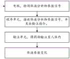
图1为根据本发明一个实施例微型全闭环人工胰腺系统工作流程图;Fig. 1 is a working flow diagram of a miniature fully closed-loop artificial pancreas system according to an embodiment of the present invention;
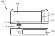
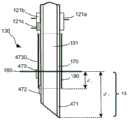
图2a为根据本发明一个实施例微型全闭环人工胰腺系统的输注管位于安装位置的剖面示意图;Figure 2a is a schematic cross-sectional view of the infusion tube at the installation position of the miniature fully closed-loop artificial pancreas system according to an embodiment of the present invention;
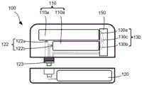
图2b为根据本发明一个实施例微型全闭环人工胰腺系统的输注管位于工作位置的剖面示意图;Fig. 2b is a schematic cross-sectional view of the infusion tube in the working position of the miniature fully closed-loop artificial pancreas system according to an embodiment of the present invention;
图3a-图3b为根据本发明另一个实施例微型全闭环人工胰腺系统的俯视示意图;3a-3b are schematic top views of a miniature fully closed-loop artificial pancreas system according to another embodiment of the present invention;
图4为根据本发明一个实施例输注单元主要结构示意图;Fig. 4 is a schematic diagram of the main structure of the infusion unit according to an embodiment of the present invention;
图5为根据本发明另一个实施例驱动单元和驱动轮相配合的结构示意图;Fig. 5 is a structural schematic diagram of cooperation between a drive unit and a drive wheel according to another embodiment of the present invention;
图6a-图6b为根据本发明一个实施例在不同视角下离合结构示意图;6a-6b are schematic diagrams of the clutch structure under different viewing angles according to an embodiment of the present invention;
图7为根据本发明一个实施例活塞和位置探测器的结构示意图;Fig. 7 is a structural schematic diagram of a piston and a position detector according to an embodiment of the present invention;
图8a-图8b为根据本发明又一个实施例驱动单元和驱动轮相配合的结构示意图;Fig. 8a-Fig. 8b are structural schematic diagrams of cooperation between the driving unit and the driving wheel according to yet another embodiment of the present invention;
图9为根据本发明又一个实施例活塞和位置探测器的结构示意图;Fig. 9 is a schematic structural diagram of a piston and a position detector according to yet another embodiment of the present invention;
图10为根据本发明又一个实施例驱动单元和驱动轮相配合的结构示意图;Fig. 10 is a structural schematic diagram of cooperation between a drive unit and a drive wheel according to yet another embodiment of the present invention;
图11为根据本发明再一个实施例驱动单元和驱动轮相配合的结构示意图;Fig. 11 is a structural schematic diagram of cooperation between a drive unit and a drive wheel according to yet another embodiment of the present invention;
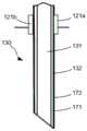
图12a-图12b为根据本发明一个实施例输注管和电极的局部纵向剖面图;12a-12b are partial longitudinal cross-sectional views of an infusion tube and electrodes according to an embodiment of the present invention;
图13a-图13b为根据本发明另一个实施例输注管和电极的局部纵向剖面图;13a-13b are partial longitudinal sectional views of an infusion tube and an electrode according to another embodiment of the present invention;
图14为根据本发明又一个实施例输注管和三电极的局部纵向剖面图;Fig. 14 is a partial longitudinal sectional view of an infusion tube and three electrodes according to yet another embodiment of the present invention;
图15为根据本发明又一个实施例输注钢针外套软管的局部纵向剖面图;Fig. 15 is a partial longitudinal sectional view of an infusion needle sheath hose according to yet another embodiment of the present invention;
图16a为根据本发明又一个实施例具有多个导电区域的输注管的局部纵向剖面图;Figure 16a is a partial longitudinal cross-sectional view of an infusion tube having multiple conductive regions according to yet another embodiment of the present invention;
图16b-图16c为根据本发明又一个实施例具有多个导电区域的输注管的局部横向剖面图;16b-16c are partial transverse cross-sectional views of an infusion tube having multiple conductive regions according to yet another embodiment of the present invention;
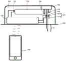
图17为根据本发明又一个实施例微型全闭环人工胰腺系统和远程设备的结构示意图。Fig. 17 is a schematic structural diagram of a miniature fully closed-loop artificial pancreas system and remote equipment according to yet another embodiment of the present invention.
具体实施方式Detailed ways
如前所述,现有技术的设备在维持体液参数稳定时,检测和输注分开进行,需要在人体表面多处穿刺,增大用户痛感的同时,也增加了用户感染的风险。As mentioned above, when maintaining the stability of body fluid parameters, the equipment in the prior art separates detection and infusion, which requires multiple punctures on the surface of the human body, which not only increases the pain of the user, but also increases the risk of infection for the user.
经研究发现,造成上述问题的原因为:传感器检测设备和药物输注设备为两个独立的单元。或者即使两者集中在一体结构上,也会在体表形成多个穿刺位置。After research, it is found that the reason for the above problems is that the sensor detection device and the drug infusion device are two independent units. Or even if the two are concentrated on an integral structure, multiple puncture locations will be formed on the body surface.
为了解决该问题,本发明提供了一种微型全闭环人工胰腺系统,具有导电区域的输注管本身作为检测分析物参数的电极和药物输注通道,一次一个位置穿刺即可实现检测和输注的目的。In order to solve this problem, the present invention provides a miniature fully closed-loop artificial pancreas system. The infusion tube itself with a conductive area serves as an electrode for detecting analyte parameters and a drug infusion channel, and the detection and infusion can be realized by puncturing one position at a time the goal of.
现在将参照附图来详细描述本发明的各种示例性实施例。应理解,除非另外具体说明,否则在这些实施例中阐述的部件和步骤的相对布置、数字表达式和数值不应被理解为对本发明范围的限制。Various exemplary embodiments of the present invention will now be described in detail with reference to the accompanying drawings. It should be understood that the relative arrangements of components and steps, numerical expressions and values set forth in these embodiments should not be construed as limiting the scope of the present invention unless specifically stated otherwise.
此外,应当理解,为了便于描述,附图中所示出的各个部件的尺寸并不必然按照实际的比例关系绘制,例如某些单元的厚度、宽度、长度或距离可以相对于其他结构有所放大。In addition, it should be understood that for the convenience of description, the dimensions of the various components shown in the drawings are not necessarily drawn according to the actual scale relationship, for example, the thickness, width, length or distance of some units may be enlarged relative to other structures .
以下对示例性实施例的描述仅仅是说明性的,在任何意义上都不作为对本发明及其应用或使用的任何限制。这里对于相关领域普通技术人员已知的技术、方法和装置可能不作详细讨论,但在适用这些技术、方法和装置情况下,这些技术、方法和装置应当被视为本说明书的一部分。The following description of the exemplary embodiments is illustrative only and is not intended to limit the invention and its application or use in any way. Techniques, methods and devices known to persons of ordinary skill in the related art may not be discussed in detail here, but when applicable, these techniques, methods and devices should be regarded as a part of this specification.
应注意,相似的标号和字母在下面的附图中表示类似项,因此,一旦某一项在一个附图中被定义或说明,则在随后的附图说明中将不需要对其进行进一步讨论。It should be noted that like numerals and letters denote like items in the following figures, therefore, once an item is defined or illustrated in one figure, it will not require further discussion in subsequent figure descriptions .
图1为本发明实施例微型全闭环人工胰腺系统工作流程图。Fig. 1 is a working flow chart of the miniature fully closed-loop artificial pancreas system according to the embodiment of the present invention.
本发明实施例微型全闭环人工胰腺系统包括三个基本部分:电极、程序单元和输注单元。体液分析物参数信息被电极获得,转化为电信号。通过电极和/或电极导线,电信号被传入程序单元。经过分析体液分析物参数信号,程序单元向输注单元发送是否进行药物输注的信号,以控制输注单元是否进行药物输注,进而稳定体液参数。体液分析物参数实时被电极检测,不断进行检测输注循环。此过程不需要人为干预,直接通过程序分析来完成,以控制体液参数的稳定。The miniature fully closed-loop artificial pancreas system of the embodiment of the present invention includes three basic parts: electrodes, program unit and infusion unit. The body fluid analyte parameter information is obtained by electrodes and converted into electrical signals. Via the electrodes and/or electrode leads, electrical signals are passed into the program unit. After analyzing the body fluid analyte parameter signal, the program unit sends a signal to the infusion unit whether to perform drug infusion, so as to control whether the infusion unit performs drug infusion, thereby stabilizing the body fluid parameters. The body fluid analyte parameters are detected by the electrodes in real time, and the detection infusion cycle is continuously performed. This process does not require human intervention, and is directly completed through program analysis to control the stability of body fluid parameters.
图2a-图2b分别为本发明实施例微型全闭环人工胰腺系统100的剖面图,微型全闭环人工胰腺系统100为一体结构。图2a为输注管130处于安装位置,图2b为输注管130处于工作位置。2a-2b are cross-sectional views of the miniature fully closed-loop
程序单元120包括输入端121和输出端122。输入端121用于接收体液分析物参数信号。在本发明实施例中,输入端121包括电连接区121a和121b。在工作状态下,电连接区与电极或电极导线电连接,以接收参数信号。在本发明的其他实施例中,根据电极数量,输入端121还可以包括更多个电连接区。输出端122和输注单元110电连接,以实现程序单元120对输注单元110的控制。The
在本发明实施例微型全闭环人工胰腺系统的使用过程中,输注管130和输入端121会发生相对滑动,因此输入端121设置为弹性件。选用弹性件保证输注管130和输入端121之间过盈配合,以避免电接触不良。弹性件包括:导电胶条、定向导电的导电硅胶、导电环、导电球等。当电极数量比较多时,电连接区相对密集,此时可根据不同的结构设计,弹性件可以选择上述中的一种或者多种组合。During the use of the micro fully closed-loop artificial pancreas system of the embodiment of the present invention, the
在本发明实施例中,输注管130安装在安装装置150上。当输注管130位于安装位置时,安装装置150凸出于微型全闭环人工胰腺系统100外壳表面,如图2a所示。当输注管130被安装至工作位置时,安装装置150进入微型全闭环人工胰腺系统100内,其顶部与微型全闭环人工胰腺系统100壳体成为一体结构,如图2b所示。用户在使用之前,安装装置150携带着输注管130处于安装位置。用户在使用时,将微型全闭环人工胰腺系统100贴在人体表面后,按下安装装置150完成安装操作,微型全闭环人工胰腺系统可开始正常工作。相比于其他的输注管安装方法,本发明实施例的安装方法减少用户在安装时的操作步骤,使安装更便捷和灵活,改善了用户体验。In the embodiment of the present invention, the
输注管130在安装装置150中的设置方式可以有多种,在这里不做具体限制。具体的,在本发明实施例中,安装装置150另一侧还凸出部分输注管130(图2a和2b中虚线所示),用于后续和输注单元110出口连接,实现药物流通。The
在本发明的实施例中,输注管130包括一个或多个导电区域。在这里,导电区域是指输注管130不同位置的管壁,管壁本身可导电。导电区域的材料包括不锈钢、金属合金或者其他导电材料,在这里并不做具体限制。具体的,在本发明实施例中,输注管130的整体材料为不锈钢。此时输注管130整体作为一个导电区域。输注管130本身作为一个电极能够减少电极设计的数量,降低了电极设计的工艺难度。In an embodiment of the invention,
在本发明的其他实施例中,输注管130上还包括有与输入端121相连接的电接触区140。如图2a所示,当输注管130位于安装位置时,电接触区140不与输入端121电连接。且输注管130的另一端也不与输注单元110出口连通。如图2b所示,当输注管130被安装至工作位置时,输注管130的一端刺入皮下(图2b中输注管实线部分示意),另一端(图2b中输注管虚线部分示意)与输注单元110出口相连通,进而建立了药物从输注单元110到人体组织液的流通通道。同时,电接触区140到达输入端121的电连接区位置,实现程序单元120和电接触区140之间的电连接。In other embodiments of the present invention, the
需要说明的是,即使输注管130和输注单元110相连通的同时,输入端121和输注管130的电接触区140电连接,只要输注管130没有刺入皮下,程序单元120会处于非工作状态,此时微型全闭环人工胰腺系统不产生分析物参数信号,也不会发出是否进行输注的指令。因此,在本发明其它的实施例中,当输注管130位于安装位置时,电接触区140也可以和输入端121的电连接区电连接,或者输注管130也可以与输注单元110出口连通,这里并不做具体限制。It should be noted that even if the
在本发明实施例中,还包括用于将微型全闭环人工胰腺系统100贴在皮肤表面的医用胶布160,以将程序单元120、输注单元110、电极和输注管130作为一个整体粘贴在皮肤上。当输注管130被安装至工作位置时,输注管130刺入皮下的部分为13。In the embodiment of the present invention, it also includes a medical
图3a为本发明另一实施例的微型全闭环人工胰腺系统100俯视图。Fig. 3a is a top view of a miniature fully closed-loop
在本发明的一个实施例中,微型全闭环人工胰腺系统100包括两个部分。程序单元120设置在一个部分中,输注单元110设置于另一个部分中,两个部分通过防水电插塞123电连接。输注单元110所在部分一次使用后可抛弃,而程序单元120所在部分可重复使用,节约用户的成本。In one embodiment of the present invention, the miniature fully closed-loop
在本发明的其它实施例中,微型全闭环人工胰腺系统100还可以由更多个部分组成,不需要电连接的部分之间使用普通防水插塞相连接即可。In other embodiments of the present invention, the miniature closed-loop
图3b为本发明另一个实施例的微型全闭环人工胰腺系统100俯视图。Fig. 3b is a top view of a miniature fully closed-loop
在本发明实施例中,微型全闭环人工胰腺系统100包括两个部分,且输注单元110包括两个输注子单元110a和110b。输注子单元110a和110b可以放置不同的药物,如放置胰岛素、胰高血糖素、抗生素、营养液、镇痛药、吗啡、抗凝血剂、基因治疗药物、心血管药物或化疗药物等。输注子单元110a和110b分别与输出端122a和122b电连接,实现程序单元120对输注单元110的控制。输注子单元110a和110b的出口分别用于与输注管130a和130b部分连通。输注管130a、130b部分分别和输注管130c部分连通。输注管130c部分用于刺入皮下,进而建立了两种药物从输注单元110流向体液中的通道。即微型全闭环人工胰腺系统仍然只在一个位置刺入皮下。在本发明实施例中,当体液分析物参数信号被传入程序单元120后,程序单元120可以向不同的输注子单元输出不同的输注信号控制是否需要输注药物,实现对体液分析物参数精确检测与控制,以稳定用户的生理状态。In the embodiment of the present invention, the miniature fully closed-loop
在本发明的其它实施例中,根据实际需求,还可以有更多个输注子单元,且多个输注子单元可以设置于微型全闭环人工胰腺系统100的不同部分中,在这里并不做具体限制。In other embodiments of the present invention, according to actual needs, there may be more infusion subunits, and multiple infusion subunits may be set in different parts of the miniature fully closed-loop
请参考图4-图5。图4为本发明实施例微型全闭环人工胰腺系统输注单元的主要结构示意图。图5为图4中驱动部1510a和1510b推动轮齿1410运动的结构示意图。Please refer to Figure 4-Figure 5. Fig. 4 is a schematic diagram of the main structure of the infusion unit of the miniature fully closed-loop artificial pancreas system according to the embodiment of the present invention. FIG. 5 is a structural schematic diagram of the driving parts 1510 a and 1510 b pushing the
输注单元主要包括储药单元1000、活塞1200、刚性螺杆1300、驱动轮1400、驱动单元1500、旋转轴1600、回弹单元1700和动力单元1800。The infusion unit mainly includes a
活塞1200用于将液体药物输注到体内。
刚性螺杆1300分别与活塞1200和驱动轮1400相连接。在本发明实施例中,驱动轮1400通过转动,以螺纹的方式驱动刚性螺杆1300前进,进而推动设置于储药单元1000中的活塞1200向前运动,以达到输注药物的目的。The
驱动轮1400的圆周表面设置有轮齿1410。轮齿1410为齿轮齿或者棘轮齿。具体的,在本发明实施例中,轮齿1410为棘轮齿。棘轮齿能够更容易被推动,提高驱动效率。The circumferential surface of the
驱动单元1500的一端设置一个驱动部1510,用于推动轮齿1410,进而推动驱动轮1400转动。驱动单元1500与旋转轴1600活动连接,同时还分别与动力单元1800和回弹单元1700相连接。动力单元1800和回弹单元1700相互配合使驱动单元1500绕着旋转轴1600往复旋转,如图5中R方向所示。驱动单元1500进行一次往复旋转,驱动轮1400驱动刚性螺杆1300前进一个步长,进而推动活塞1200完成一次药物输注。One end of the
在本发明实施例中,回弹单元1700为弹簧。在本发明的其它实施例中,回弹单元1700为弹片、弹性板、弹性棒等,这里对回弹单元1700的类型及材料选择并不做具体限制,只要能够满足使驱动单元1500向回复方向旋转的条件即可。In the embodiment of the present invention, the
动力单元1800为线性驱动器。在本发明的实施例中,动力单元1800为电驱动型线性驱动器或者电加热型线性驱动器。通过交替通断电,动力单元1800输出或停止输出动力。在本发明的其它实施例中,动力单元1800还可以是其他类型,如微型气囊等。The
在本发明实施例中,当动力单元1800以FP拉动驱动单元1500时,驱动单元1500绕着旋转轴1600逆时针旋转,带动驱动部1510推动轮齿1410前进,驱动轮1400转动,进而驱动刚性螺杆1300向DA方向前进。此时,回弹单元1700产生逐渐增强的弹力FR。当动力单元1800停止提供动力,驱动单元1500在弹力FR的作用下绕着旋转轴1600顺时针旋转。此时,驱动部1510停止推动轮齿1410,而在相邻轮齿1410表面滑动,直至滑动到下一个驱动位置,驱动轮1400停止转动。驱动单元1500完成了一次往复旋转。In the embodiment of the present invention, when the
在这里需要说明的是,为了尽量降低制造公差带来的影响,且确保每次往复旋转均能够推动轮齿1410,驱动部1510滑动到下一个驱动位置后,驱动单元1500可以再顺时针旋转适当距离,使驱动部1510稍稍远离驱动位置,保证输注安全。It should be noted here that, in order to minimize the impact of manufacturing tolerances and ensure that each reciprocating rotation can push the
优选的,在本发明实施例中,FP方向和FR、DA方向均平行。这样的平行设计充分利用输注单元内部的空间和结构关系,使内部结构更紧凑。在本发明的其它实施例中,FP方向和FR方向也可以不平行,这里并不作具体限制,只要能够达到使驱动单元1500往复旋转的目的即可。Preferably, in the embodiment of the present invention, the direction ofFP is parallel to the directions ofFR andDA . Such a parallel design makes full use of the internal space and structural relationship of the infusion unit, making the internal structure more compact. In other embodiments of the present invention, theFP direction and theFR direction may not be parallel, and there is no specific limitation here, as long as the purpose of reciprocating rotation of the
在本发明实施例中,还设置有能使驱动单元1500停止旋转的挡墙1710和1720。驱动单元1500与挡墙1710或1720接触触发电信号,以使程序单元控制动力单元1800力的输出。在本发明的一个实施例中,可以只设置挡墙1710或者只设置挡墙1720,使驱动单元1500在不同方向上停止旋转。并结合时间控制器,程序单元可控制动力单元1800力的输出。本发明的其他实施例也可以不设置挡墙,驱动单元1500的旋转完全由程序单元中的时间控制器控制。In the embodiment of the present invention, retaining
需要说明的是,本发明实施例对挡墙1710或1720的位置不作具体限制,只要满足使驱动单元1500停止旋转的条件即可。It should be noted that the embodiment of the present invention does not specifically limit the position of the
图6a-图6b为本发明实施例离合结构1310结构示意图。图6b为沿图6a中剖面线B-B’视角的离合结构1310截面示意图。6a-6b are structural schematic diagrams of a
本发明实施例还包括离合结构1310,离合结构1310设置于驱动轮1400的中心位置,且刚性螺杆1300穿过离合结构1310。离合结构1310上设置有与刚性螺杆1300外螺纹相配合的内螺纹,如图6b所示。在进行药物输注时,驱动轮1400带动离合结构同步转动,离合结构通过内螺纹驱动刚性螺杆1300前进。明显的,在本发明的实施例中,刚性螺杆1300只是在自身轴向方向前进,而不进行旋转。在本发明的其它实施例中,驱动轮1400自身带有内螺纹,可直接和刚性螺杆1300外螺纹相配合。The embodiment of the present invention also includes a
图7为本发明实施例的金属件1100和位置探测器1900的结构示意图。FIG. 7 is a schematic structural diagram of a
本发明实施例的微型全闭环人工胰腺系统还包括一个或多个位置探测器1900。位置探测器1900和金属件1100相互作用以检测金属件1100的位置,进而对活塞1200定位,以判断储药单元1000中的药物余量。具体的,在本发明实施例中,金属件1100为磁性金属件,位置探测器1900为磁性位置探测器。当金属件1100位于某一位置时,位置探测器1900处具有一定的磁场大小和方向,进而对活塞1200精确定位。当活塞1200在运动时,位置探测器1900处磁场的大小和方向随之变化,实时检测活塞1200的位置。位置探测器1900将磁信号或者磁信号变化发送至控制单元,信号被处理后转化为活塞1200位置信息,进而提供剩余药量信息。The miniature fully closed-loop artificial pancreas system of the embodiment of the present invention also includes one or
根据储药单元1000的规格,位置探测器1900的个数为一个、两个或两个以上。具体的,在本发明实施例中,位置探测器1900的个数为七个。在本发明的其它实施例中,位置探测器1900的个数为两个或者只有一个。According to the specifications of the
需要说明的是,当位置探测器1900多于两个时,优选的,位置探测器1900线性等间距设置。位置探测器1900设置在输注单元中,或设置在程序单元120的与活塞1200行程对应位置处,或嵌入储药单元1000侧壁中,或设计在储药单元1000内表面。位置探测器1900还可以以其他方式排列,在这里并不作具体限制,只要能够满足对活塞1200定位的条件即可。It should be noted that, when there are more than two
如前所述,刚性螺杆1300只沿着自身的轴向运动,而不进行旋转,因此活塞1200中的金属件1100与刚性螺杆1300固定连接后也只沿着刚性螺杆1300的轴向方向非旋转式前进。与螺杆旋转定位的方式相比,本发明实施例只在一维轴向方向或者在二维平面内检测磁场信号,原理更简单,定位更精确,操作和结构设计更简便,降低了设计和生产成本。As mentioned above, the
图8a-图8b为本发明另一个实施例驱动部2510推动轮齿2410运动的结构示意图。该实施例和前述实施例的不同之处在于动力单元拉力FP的方向与刚性螺杆2300前进方向DA垂直,其他结构设计与前述实施例相同。8a-8b are structural schematic diagrams of the driving
图8a为沿刚性螺杆2300轴向方向的视图,图8b为图8a的俯视结构示意图。旋转轴2600和回弹单元2700设置在底座(未示出)上。如上文所述,驱动单元2500在R方向的交替旋转带动驱动部2510推动轮齿2410,使驱动轮2400向W方向转动,进而驱动刚性螺杆2300在DA方向上前进。本发明实施例驱动单元2500的驱动原理与前述实施例一致,在此不再赘述。Fig. 8a is a view along the axial direction of the
图9为本发明实施例的金属件2100和位置探测器2900的结构示意图。FIG. 9 is a schematic structural diagram of a
在本发明实施例中,刚性螺杆2300由金属材料制成。金属件2100与刚性螺杆2300固定电连接,金属件2100在某一位置与对应的位置探测器2900组成电容器,产生电信号。当活塞2200运动时,电容随极板面积变化而变化,对应的位置探测器2900产生变化的电信号,对活塞2200实施精确定位。对应的位置探测器2900将电信号传入控制单元,转化活塞2200位置信息,进而输出药物余量信息。具体的,在本发明实施例中,为了精确定位,位置探测器2900有多个,其设置方式如前文所述。In an embodiment of the present invention, the
图10为本发明又一个实施例驱动部3510a或3510b推动轮齿3410运动的结构示意图。与前文所述实施例的不同之处在于:设置有两个共轴旋转的驱动单元3500a和3500b。FIG. 10 is a schematic structural diagram of the driving
驱动单元3500a在动力单元3800a和回弹单元3700a的作用下绕着旋转轴3600在R方向往复旋转。同样,驱动单元3500b在动力单元3800b和回弹单元3700b的作用下绕着旋转轴3600在R方向往复旋转。在本发明实施例中,两个驱动单元的旋转互不干扰。The
优选的,在本发明实施例中,驱动单元3500a和驱动单元3500b非同步旋转。即,当驱动单元3500a的驱动部3510a推动轮齿3410运动时,驱动单元3500b的驱动部3510b在轮齿3410表面滑动。当驱动部3510b滑动至下一个轮齿3410的驱动位置后,控制单元控制动力单元3800a停止对驱动单元3500a输出动力,转而控制动力单元3800b对驱动单元3500b输出动力。此时,驱动单元3500a在回弹单元3700a作用下沿顺时针方向旋转,驱动部3510a在轮齿表面滑动,而驱动部3510b推动轮齿3410。依次交替推动,进而驱动单元3500a和3500b完成对驱动轮3400的交替推动。Preferably, in the embodiment of the present invention, the
在本发明的实施例中,动力单元3800a和3800b拉力FP、回弹单元3700a和3700b的弹力FR以及刚性螺杆3300前进方向DA如图所示。如前文所述,拉力FP的方向和刚性螺杆3300前进方向DA平行。In the embodiment of the present invention, the pulling forceFP of the
图11为本发明再一个实施例驱动部4510a或4510b推动轮齿4410运动的结构示意图。该实施例与前述实施例的不同之处在于:驱动单元4500a和4500b分别设置于驱动轮4400的两侧。FIG. 11 is a structural schematic diagram of the driving
类似上文所述,驱动部4510a和4510b分别交替推动轮齿4410,动力单元4800a和4800b的动力输出均由控制单元控制。Similar to the above, the driving
需要说明的是,在本发明实施例中,动力单元4800a的拉力FP’的方向和动力单元4800b的拉力FP”的方向相反。明显的,回弹单元4700a的回复力FR’的方向和回弹单元4700b的回复力FR”的方向也相反。It should be noted that, in the embodiment of the present invention, the direction of the pulling forceFP ' of the
同样,在本发明实施例中,驱动单元4500a和4500b非同步旋转。即,当驱动单元4500a的驱动部4510a推动轮齿4410运动时,驱动单元4500b的驱动部4510b在轮齿4410表面滑动。当驱动部4510b滑动至下一个轮齿4410的驱动位置后,控制单元控制动力单元4800a停止对驱动单元4500a输出动力,转而控制动力单元4800b对驱动单元4500b输出动力,驱动单元4500a在回弹单元4700a作用下沿顺时针方向回复旋转,驱动部4510a在轮齿4410表面滑动,而驱动部4510b推动轮齿4410。依次交替推动,驱动单元4500a和4500b完成对驱动轮4400的交替推动。明显的,驱动单元4500a和4500b驱动旋转或回复旋转的方向相反。Also, in the embodiment of the present invention, the
需要说明的是,在本发明的其它实施例中,还包括更多个驱动单元,或者包括更多个驱动轮,不同的驱动单元分别推动相应的驱动轮转动。如在本发明的一个实施例中,输注单元设置一个驱动单元和两个驱动轮,驱动单元只驱动一个驱动轮,另一个驱动轮用于平衡力的作用。此时,两个驱动轮的间距可相对紧凑装配。It should be noted that, in other embodiments of the present invention, more driving units are included, or more driving wheels are included, and different driving units drive corresponding driving wheels to rotate respectively. For example, in one embodiment of the present invention, the infusion unit is provided with a driving unit and two driving wheels, the driving unit only drives one driving wheel, and the other driving wheel is used for balancing force. At this time, the distance between the two drive wheels can be assembled relatively tightly.
在本发明的实施例中,当设置两个或者两个以上的驱动单元时,通过控制单元控制不同拉力输出的时机,或者通过调整多个驱动部前端(如图5所示)之间的距离,输注单元能够提高输注精度。如在图10和图11中,当驱动单元均处于回复运动的终点时,两个驱动部前端的距离相差n/2(n为奇数)个齿距,此时当驱动轮最多转动1/2个齿距就有一个驱动部到达下一个驱动位置,即可开始下一次驱动。与只有一个驱动单元相比,输注精度提高一倍。在本发明的实施例中,n=1、3、5。为了避免出现相邻两个驱动部可能的干涉,优选的,n=3。驱动轮一次最多只转动半个齿距即可开始下一次转动,驱动单元的旋转幅度进一步减小,输注单元的内部结构将更紧凑,微型全闭环人工胰腺系统的体积更小。In an embodiment of the present invention, when two or more driving units are provided, the timing of different pulling force outputs is controlled by the control unit, or the distance between the front ends of multiple driving parts (as shown in FIG. 5 ) is adjusted. , the infusion unit can improve infusion accuracy. As shown in Figure 10 and Figure 11, when the drive units are at the end of the return movement, the distance between the front ends of the two drive parts differs by n/2 (n is an odd number) tooth pitch, and at this time when the drive wheel rotates at most 1/2 One tooth pitch has a driving part to reach the next driving position, and the next driving can be started. Compared with only one drive unit, the infusion accuracy is doubled. In an embodiment of the present invention, n=1, 3, 5. In order to avoid possible interference between two adjacent driving parts, preferably, n=3. The driving wheel can start the next rotation by only turning half a tooth pitch at most at a time, the rotation range of the driving unit is further reduced, the internal structure of the infusion unit will be more compact, and the volume of the miniature fully closed-loop artificial pancreas system will be smaller.
图12a-图12b为输注管130的局部纵向剖面图。12a-12b are partial longitudinal cross-sectional views of the
在本发明的实施例中,微型全闭环人工胰腺系统100包括多个检测分析物参数的电极,电极为输注管的可导电区域,该电极为导电区域电极。或者电极设置于输注管130管壁,该电极为管壁电极。In an embodiment of the present invention, the miniature fully closed-loop
在本发明的一个实施例中,管壁电极172镀在输注管130管壁外表面,输注管130管壁132本身作为一个导电区域电极171,管腔131用于输注药物。一般的,导电区域电极171和管壁电极172之间设置有绝缘层(未示出),以隔离导电区域电极171和管壁电极172。明显的,在本发明实施例中,输注管130本身同时作为电极和输注管道。这种设计减少了微型全闭环人工胰腺系统穿刺皮肤的位置,一次在同一个位置穿刺,即可完成分析物检测和药物输注,降低了用户感染的风险。同时,这种在输注管130管壁132上整体电镀电极层的方法能够简化输注管130制备工艺流程,便于工艺实施。In one embodiment of the present invention, the
为了便于各电极和电连接区121a和121b电连接,电接触区140处(图12a中虚线位置)需要将不锈钢管壁132暴露出来,而输注管130的其它位置镀有电极层。如图12b所示,当输注管130被安装至工作位置时,导电区域电极171和管壁电极172分别直接与输入端的电连接区121a和121b电连接,将体液分析物参数信息以电信号形式传入程序单元120。In order to facilitate the electrical connection between the electrodes and the
需要说明的是,本发明实施例当输注管130被安装至工作位置时,管壁电极172的一部分位于皮下组织液中,一部分位于皮上,可以实现电信号在管壁电极172上传输。下文其它实施例中相应的电极设置具备同样的功能,后续不再详述。It should be noted that, in the embodiment of the present invention, when the
在本发明实施例中,微型全闭环人工胰腺系统100只有两个电极,导电区域电极171为工作电极,管壁电极172为辅助电极。在本发明的另一个实施例中,导电区域电极171为辅助电极,管壁电极172位工作电极。辅助电极为对电极。In the embodiment of the present invention, the miniature fully closed-loop
图13a-图13b为本发明另一个实施例的输注管130的局部纵向剖面图。为了便于标记和叙述,电极导线与输注管在图13a中分离示出,下文的相关结构图示与此处的方式相同,后续不再赘述。13a-13b are partial longitudinal cross-sectional views of an
在该实施例中,管壁132本身为导电区域电极271,管壁电极272设置于管壁132的部分表面,管壁132的表面还设置有与管壁电极272电连接的电极导线2720。电极导线2720和管壁132之间形成有绝缘材料层(未示出)。当输注管130被安装至工作位置时,输入端的电连接区121a、121b分别与导电区域电极271、电极导线2720电连接。此时,管壁电极272与输入端为间接电连接,同样可以将体液参数信号传入程序单元。In this embodiment, the
图13b中的管壁电极272设置为环形,环形的管壁电极272环绕在部分管壁132的外表面。管壁电极272还可以有其它形状,这里不做具体限制。The
图14为本发明又一个实施例的输注管130的局部纵向剖面图。Fig. 14 is a partial longitudinal sectional view of an
在本发明实施例中,输注管130上设置三个电极:导电区域电极371、管壁电极372和管壁电极373。输注管130管壁132本身作为导电区域电极371,管壁电极372和管壁电极373分别设置在管壁132的部分外表面。同时,管壁132的表面还设置有分别与管壁电极372、管壁电极373电连接的电极导线3720、3730。当输注管130被安装至工作位置时,导电区域电极371、电极导线3720、电极导线3730分别与输入端电连接区121a、121b、121c电连接,进而实现输入端与各个电极电连接。管壁电极372和管壁电极373的形状可以有多种,这里不作具体限制。In the embodiment of the present invention, three electrodes are provided on the infusion tube 130 : a
在本发明实施例中,为了简化电连接区的设计,输入端的弹性件为导电硅胶或者导电环。在硅胶中掺杂不同的元素,可以实现其定向导电,如水平方向导电,竖直方向不导电。这样设计,即使121a和121c接触相邻,两者之间也是相互绝缘。而电连接区121b可以使用导电胶条或者导电球等,这里不做具体限制。In the embodiment of the present invention, in order to simplify the design of the electrical connection area, the elastic member at the input end is a conductive silicone or a conductive ring. Doping different elements in silica gel can realize directional conduction, such as conduction in the horizontal direction and non-conduction in the vertical direction. In such a design, even if 121a and 121c are adjacent to each other, they are insulated from each other. The
在本发明实施例中,导电区域电极371为工作电极,管壁电极372和管壁电极373均为辅助电极。此时,导电区域电极371与管壁电极372或与管壁电极373可组成不同电极组合,即两个电极组合共用导电区域电极371。程序单元120可选择不同的电极组合检测体液分析物参数信息。形成电极组合后,一方面,当一个工作的电极组合出现故障,程序单元120可以根据情况选择其他电极组合进行检测,确保体液信号的检测过程不间断。另一方面,程序单元120可以选择多个电极组合同时工作,将同一时刻同一参数的多组数据进行统计分析,提高分析物参数的准确性,进而输出更准确的药物输注信号。In the embodiment of the present invention, the
同样的,导电区域电极371、管壁电极372和管壁电极373中包括一个工作电极和两个辅助电极,且可根据实际需求进行任意选定。在本发明的另一个实施例中,导电区域电极371、管壁电极372和管壁电极373中包括一个辅助电极和两个工作电极,同样可根据实际需求进行任意选定,在这里并不做具体限制。Similarly, the
如在本发明的一个实施例中,导电区域电极371为工作电极,管壁电极372、373均为辅助电极,管壁电极372、373分别作为对电极、参比电极使用,进而组成三电极体系。同样的,根据实际需求,三个电极可以任意选定,在这里并不做具体限制。For example, in one embodiment of the present invention, the
同样的,在本发明的其它实施例中,还可以设置更多个电极。电极中包括多个工作电极和多个辅助电极,但应保证输注管130的导电区域至少作为一个电极。此时,每个电极组合包括工作电极和辅助电极,因此多个电极可以组成多个电极组合。根据需求,程序单元120可以选择一个或多个电极组合对体液分析物参数进行检测。Likewise, in other embodiments of the present invention, more electrodes may also be provided. The electrodes include multiple working electrodes and multiple auxiliary electrodes, but it should be ensured that the conductive area of the
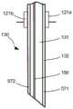
图15为本发明又一个实施例的输注管130的局部纵向剖面图。为了便于标记和描述,图7中软管180管壁和输注钢针170外壁分离示出。Fig. 15 is a partial longitudinal sectional view of an
在本发明实施例中,输注管130包括输注钢针170和套在输注钢针170外壁的软管180。外套软管180,是因为软管180的表面更容易设置电极,降低电极制造的工艺难度,提高制备效率。另外,软管180的管壁材料可根据需要进行选择,如其管壁只能允许特定分析物透过,减弱其它物质的干扰,提高分析物参数的检测准确性。In the embodiment of the present invention, the
输注钢针的针腔131作为药物输注通道,输注管130管壁包括钢针外壁和软管壁。输注钢针170本身整体作为一个导电区域电极471,管壁电极472设置于输注钢针170外壁表面,管壁电极473设置于软管180外表面。此时,管壁电极472设置于输注管130的管壁中。The
在上述实施例中,管壁电极472可以被软管180部分覆盖、全部覆盖或者管壁电极472裸露在组织液中。管壁电极473还可以设置于软管180内表面,即设置于钢针壁和软管壁之间,管壁电极473通过电极导线4730与电连接区121c电连接。当管壁电极472(管壁电极472的电极导线未示出)被软管180部分覆盖或者全部覆盖,或者管壁电极473设置于软管180内表面时,软管180管壁材料为渗透膜或者半渗透膜。这样的选择能够便于体液分析物透过软管180管壁,被电极检测到,进而在不影响检测的情况下,提高电极位置设计的灵活性。In the above embodiments, the
在本发明实施例中,当输注管130被安装至工作位置时,软管180和输注钢针170刺入皮下的深度有一定关系。在这里,深度是指软管180或者输注钢针170刺入皮下的远端分别与皮肤表面的距离,如图15所示。一般的,输注钢针170的硬度大于软管180。如图15所示,在皮下部分13范围内,软管180进入皮下的深度为d1,输注钢针170进入皮下的深度为d2,d1≤d2。这种设计能够使输注管130顺利刺入皮下。In the embodiment of the present invention, when the
图16a-图16c为本发明又一个实施例的输注管130的局部纵向剖面图。图16a为输注管130的纵向剖面图,图16b和图16c为输注管130的横向剖面图。16a-16c are partial longitudinal cross-sectional views of an
请参考图16a和图16b,图16b为图16a输注管130横向剖面示意图。Please refer to Fig. 16a and Fig. 16b, Fig. 16b is a schematic cross-sectional view of the
在本发明实施例中,输注管130的管壁132包括多个导电区域,多个导电区域中的一个或者多个作为电极。如当管壁132包括两个导电区域时,其分别作为导电区域电极571和导电区域电极572。导电区域电极571和导电区域电极572可分别为工作电极和辅助电极,并分别与电连接区121a和121b电连接,以进行电信号传输。输注管本身不同的导电区域作为电极,能进一步减少管壁表面的电极设计,减少了输注管的生产流程。绝缘部190实现输注管130两个导电区域之间电绝缘。In the embodiment of the present invention, the
请参考图16c,输注管130整体由三个导电区域构成,相邻导电区域被绝缘部190隔开。输注管130本身分别作为三个电极:导电区域电极671、672、673。导电区域电极671为工作电极,导电区域电极672、673为辅助电极,或者根据前文所述的实际需求进行选定。Please refer to FIG. 16 c , the
请参考图17,远程设备200和微型全闭环人工胰腺系统100之间的信号传输。Please refer to FIG. 17 , the signal transmission between the
本发明实施例还包括远程设备200。远程设备200包括不限于手持机、移动终端等。远程设备200和程序单元120之间互相传输无线信号。程序单元120可将体液分析物参数信息或药物输注信息(包括输注或不输注)发送至远程设备200。远程设备200可接收、记录、存储、显示体液参数信息或输注信息,以及包括其它功能选项。用户通过远程设备200可随时查看历史或实时信息。通过远程设备200,用户还可以人为远程选定输注信息,并将信息无线传输至程序单元120,在程序单元120认定安全的前提下,控制输注单元是否进行药物输注,进而实现远程手动操控。The embodiment of the present invention also includes a
在本发明的一些实施例中,微型全闭环人工胰腺系统100还包括更多个电极,进而组成多个前文所述的电极组合。用户可以根据情况人为选择不同的电极组合检测体液参数。In some embodiments of the present invention, the miniature fully closed-loop
综上所述,本发明公开了一种微型全闭环人工胰腺系统,输注管同时具备输注和检测的功能,减少在皮肤表面穿刺的次数。一次在一个位置穿刺,即可完成分析物检测和药物输注,降低了用户感染的风险。In summary, the present invention discloses a miniature fully closed-loop artificial pancreas system. The infusion tube has the functions of infusion and detection at the same time, reducing the number of punctures on the skin surface. Analyte detection and drug infusion can be completed by puncturing one site at a time, reducing the risk of infection for users.
虽然已经通过示例对本发明的一些特定实施例进行了详细说明,但是本领域的技术人员应该理解,以上示例仅是为了进行说明,而不是为了限制本发明的范围。本领域的技术人员应该理解,可在不脱离本发明的范围和精神的情况下,对以上实施例进行修改。本发明的范围由所附权利要求来限定。Although some specific embodiments of the present invention have been described in detail through examples, those skilled in the art should understand that the above examples are for illustration only, rather than limiting the scope of the present invention. Those skilled in the art will appreciate that modifications can be made to the above embodiments without departing from the scope and spirit of the invention. The scope of the invention is defined by the appended claims.
Claims (23)
Applications Claiming Priority (2)
| Application Number | Priority Date | Filing Date | Title |
|---|---|---|---|
| PCT/CN2019/096673WO2021012075A1 (en) | 2019-07-19 | 2019-07-19 | Integrated drug infusion device |
| CNPCT/CN2019/096673 | 2019-07-19 |
Publications (2)
| Publication Number | Publication Date |
|---|---|
| CN112237659A CN112237659A (en) | 2021-01-19 |
| CN112237659Btrue CN112237659B (en) | 2023-03-14 |
Family
ID=74168099
Family Applications (7)
| Application Number | Title | Priority Date | Filing Date |
|---|---|---|---|
| CN201911421196.0AActiveCN112237659B (en) | 2019-07-19 | 2019-12-31 | Miniature full-closed-loop artificial pancreas system |
| CN201911421195.6AActiveCN112237656B (en) | 2019-07-19 | 2019-12-31 | Detect artifical pancreas equipment of infusion integral type closed loop |
| CN201911413591.4AActiveCN112237655B (en) | 2019-07-19 | 2019-12-31 | Intelligent control miniature full closed-loop artificial pancreas |
| CN202010486227.7AActiveCN112237429B (en) | 2019-07-19 | 2020-06-01 | Bilateral drive integrated medical device |
| CN202010485231.1AActiveCN112237428B (en) | 2019-07-19 | 2020-06-01 | Double-side driving medical device integrating infusion and detection |
| CN202010870569.9AActiveCN113117181B (en) | 2019-07-19 | 2020-08-26 | Integrated closed-loop artificial pancreas |
| CN202110603242.XAActiveCN113750319B (en) | 2019-07-19 | 2021-05-31 | An integrated closed-loop artificial pancreas with multiple infusion modes |
Family Applications After (6)
| Application Number | Title | Priority Date | Filing Date |
|---|---|---|---|
| CN201911421195.6AActiveCN112237656B (en) | 2019-07-19 | 2019-12-31 | Detect artifical pancreas equipment of infusion integral type closed loop |
| CN201911413591.4AActiveCN112237655B (en) | 2019-07-19 | 2019-12-31 | Intelligent control miniature full closed-loop artificial pancreas |
| CN202010486227.7AActiveCN112237429B (en) | 2019-07-19 | 2020-06-01 | Bilateral drive integrated medical device |
| CN202010485231.1AActiveCN112237428B (en) | 2019-07-19 | 2020-06-01 | Double-side driving medical device integrating infusion and detection |
| CN202010870569.9AActiveCN113117181B (en) | 2019-07-19 | 2020-08-26 | Integrated closed-loop artificial pancreas |
| CN202110603242.XAActiveCN113750319B (en) | 2019-07-19 | 2021-05-31 | An integrated closed-loop artificial pancreas with multiple infusion modes |
Country Status (4)
| Country | Link |
|---|---|
| US (10) | US20220211941A1 (en) |
| EP (11) | EP4631429A2 (en) |
| CN (7) | CN112237659B (en) |
| WO (8) | WO2021012075A1 (en) |
Families Citing this family (19)
| Publication number | Priority date | Publication date | Assignee | Title |
|---|---|---|---|---|
| WO2020233486A1 (en)* | 2019-05-17 | 2020-11-26 | Medtrum Technologies Inc. | Bilaterally driven drug infusion device with multiple infusion modes |
| US12403247B2 (en)* | 2019-05-17 | 2025-09-02 | Medtrum Technologies Inc. | Drug infusion device |
| WO2021012075A1 (en) | 2019-07-19 | 2021-01-28 | Medtrum Technologies Inc. | Integrated drug infusion device |
| US20220218895A1 (en)* | 2019-08-01 | 2022-07-14 | Medtrum Technologies Inc. | Driving apparatus and drug infusion device |
| EP4017357A4 (en)* | 2019-08-19 | 2023-04-19 | Medtrum Technologies Inc. | MEASURING DEVICE |
| WO2023279311A1 (en)* | 2021-07-08 | 2023-01-12 | Medtrum Technologies Inc. | Micro analyte sensor |
| CN113456071A (en)* | 2021-08-08 | 2021-10-01 | 江苏英诺麦德科技有限公司 | Blood glucose detection and hormone infusion integrated device, preparation method and artificial pancreas |
| WO2023070250A1 (en)* | 2021-10-25 | 2023-05-04 | Medtrum Technologies Inc. | Closed-loop artificial pancreas insulin infusion personalized control system |
| CN116020001A (en)* | 2021-10-25 | 2023-04-28 | 上海移宇科技股份有限公司 | Closed loop artificial pancreas insulin infusion control system |
| CN116020004A (en)* | 2021-10-25 | 2023-04-28 | 上海移宇科技股份有限公司 | Closed loop artificial pancreas insulin infusion control system |
| WO2023070245A1 (en)* | 2021-10-25 | 2023-05-04 | Medtrum Technologies Inc. | Closed-loop artificial pancreas insulin infusion control system |
| US20240416034A1 (en)* | 2021-12-28 | 2024-12-19 | Medtrum Technologies Inc. | Highly integrated drug infusion device and artificial pancreas |
| CN116350878A (en)* | 2021-12-28 | 2023-06-30 | 上海移宇科技股份有限公司 | Power Integrated Drug Infusion Set |
| WO2023122929A1 (en)* | 2021-12-28 | 2023-07-06 | Medtrum Technologies Inc. | Drug infusion device with integrated power supply and the artificial pancreas thereof |
| CN116350879A (en)* | 2021-12-28 | 2023-06-30 | 上海移宇科技股份有限公司 | Drug infusion device integrated with circuit housing and its artificial pancreas |
| CN114432536A (en)* | 2022-01-29 | 2022-05-06 | 深圳道远医疗科技有限公司 | Integrated device and method for dynamic blood glucose monitoring and insulin injection fusion |
| US20240058543A1 (en)* | 2022-08-19 | 2024-02-22 | Insulet Corporation | Multi-start leadscrew for variable filling and performance |
| WO2024155579A1 (en)* | 2023-01-17 | 2024-07-25 | Pacific Diabetes Technologies Inc | Self-inserting trocarless analyte-sensing cannula |
| CN118512684B (en)* | 2024-07-24 | 2024-10-15 | 杭州坦帕医疗科技有限公司 | Safety type needle special for puncturing and pulling out implantable drug delivery device |
Citations (12)
| Publication number | Priority date | Publication date | Assignee | Title |
|---|---|---|---|---|
| CN101208515A (en)* | 2005-03-28 | 2008-06-25 | 因苏雷特公司 | Fluid delivery device |
| CN101563022A (en)* | 2006-12-22 | 2009-10-21 | 梅丁格有限公司 | Fluid transport with in vivo electrochemical analyte sensing |
| CN101784295A (en)* | 2007-08-20 | 2010-07-21 | 马林克罗特公司 | Fluid driven medical injector |
| CN102711898A (en)* | 2009-11-30 | 2012-10-03 | 梅丁格有限公司 | Analyte monitoring and fluid dispensing system |
| CN103260678A (en)* | 2010-12-22 | 2013-08-21 | 爱尔康研究有限公司 | Device for at least one of infusing and aspirating |
| CN104168935A (en)* | 2012-01-09 | 2014-11-26 | 赛诺菲-安万特德国有限公司 | Cartridge adapter with active valve |
| CN104548258A (en)* | 2013-10-17 | 2015-04-29 | 精工爱普生株式会社 | Fluid transport apparatus, fluid infusing apparatus, and trouble determining method for transporting tube |
| CN106110445A (en)* | 2016-08-12 | 2016-11-16 | 上海移宇科技股份有限公司 | A kind of infusion system of portable medication infusion device |
| CN106139311A (en)* | 2016-08-12 | 2016-11-23 | 上海移宇科技股份有限公司 | A kind of drug-supplying system comprising position detection unit |
| CN107614036A (en)* | 2015-03-13 | 2018-01-19 | 优菲米特有限责任公司 | Portable medication injection device |
| CN108472440A (en)* | 2016-01-05 | 2018-08-31 | 比格福特生物医药公司 | Operating a Multimodal Drug Delivery System |
| WO2018204568A1 (en)* | 2017-05-05 | 2018-11-08 | Eli Lilly And Company | Closed loop control of physiological glucose |
Family Cites Families (96)
| Publication number | Priority date | Publication date | Assignee | Title |
|---|---|---|---|---|
| EP0137500B1 (en)* | 1983-10-13 | 1988-09-14 | Jürgen Prof. Dr. Morgenstern | Physiological sensor |
| IE72524B1 (en)* | 1994-11-04 | 1997-04-23 | Elan Med Tech | Analyte-controlled liquid delivery device and analyte monitor |
| GB9606829D0 (en)* | 1996-03-30 | 1996-06-05 | Jeffrey Peter | Supplying materials etc |
| JP4425465B2 (en)* | 1998-03-23 | 2010-03-03 | エラン コーポレーション ピーエルシー | Drug delivery device |
| US6270457B1 (en)* | 1999-06-03 | 2001-08-07 | Cardiac Intelligence Corp. | System and method for automated collection and analysis of regularly retrieved patient information for remote patient care |
| US6752787B1 (en)* | 1999-06-08 | 2004-06-22 | Medtronic Minimed, Inc., | Cost-sensitive application infusion device |
| CN2462944Y (en)* | 2001-01-17 | 2001-12-05 | 中国人民解放军济南军区总医院 | Needle infusion device detecting electrode |
| US20050238507A1 (en)* | 2002-04-23 | 2005-10-27 | Insulet Corporation | Fluid delivery device |
| US6656158B2 (en)* | 2002-04-23 | 2003-12-02 | Insulet Corporation | Dispenser for patient infusion device |
| US20040153032A1 (en)* | 2002-04-23 | 2004-08-05 | Garribotto John T. | Dispenser for patient infusion device |
| AU2003245872A1 (en)* | 2002-07-24 | 2004-02-09 | M 2 Medical A/S | An infusion pump system, an infusion pump unit and an infusion pump |
| US7248912B2 (en)* | 2002-10-31 | 2007-07-24 | The Regents Of The University Of California | Tissue implantable sensors for measurement of blood solutes |
| IL154243A0 (en)* | 2003-02-02 | 2003-09-17 | Silex Projectors Ltd | Stable infusion device |
| SG179411A1 (en)* | 2003-11-06 | 2012-04-27 | Lifescan Inc | Drug delivery pen with event notification means |
| US8425417B2 (en)* | 2003-12-05 | 2013-04-23 | Dexcom, Inc. | Integrated device for continuous in vivo analyte detection and simultaneous control of an infusion device |
| US7651845B2 (en)* | 2004-05-13 | 2010-01-26 | The Regents Of The University Of California | Method and apparatus for glucose control and insulin dosing for diabetics |
| US9636450B2 (en)* | 2007-02-19 | 2017-05-02 | Udo Hoss | Pump system modular components for delivering medication and analyte sensing at seperate insertion sites |
| CN101107025A (en)* | 2005-01-17 | 2008-01-16 | 诺和诺德公司 | Fluid delivery device with integrated monitoring of physiological characteristics |
| JP2008535548A (en)* | 2005-03-21 | 2008-09-04 | アボット ダイアビーティーズ ケア インコーポレイテッド | Method and system for providing an integrated pharmaceutical infusion / specimen monitoring system |
| US7945452B2 (en)* | 2005-04-11 | 2011-05-17 | Hospira, Inc. | User interface improvements for medical devices |
| US7699833B2 (en)* | 2005-05-06 | 2010-04-20 | Moberg Sheldon B | Pump assembly and method for infusion device |
| US7509156B2 (en)* | 2005-05-18 | 2009-03-24 | Clarian Health Partners, Inc. | System for managing glucose levels in patients with diabetes or hyperglycemia |
| US7534226B2 (en)* | 2005-09-26 | 2009-05-19 | M2 Group Holdings, Inc. | Dispensing fluid from an infusion pump system |
| EP3165247B1 (en) | 2006-02-09 | 2020-10-28 | DEKA Products Limited Partnership | Pumping fluid delivery systems and methods using force application assembley |
| WO2007093981A2 (en)* | 2006-02-15 | 2007-08-23 | Medingo Ltd. | Systems and methods for sensing analyte and dispensing therapeutic fluid |
| WO2008000634A1 (en)* | 2006-06-30 | 2008-01-03 | Novo Nordisk A/S | Perfusion device with compensation of medical infusion during wear-time |
| WO2008022225A2 (en)* | 2006-08-15 | 2008-02-21 | Optiscan Biomedical Corporation | Method and apparatus for analyte measurements in the presence of interferents |
| CN101125086A (en)* | 2006-08-18 | 2008-02-20 | 刘胜 | Closed-loop automatic controlling insulin-injecting system |
| EP1961436B1 (en)* | 2007-02-24 | 2016-08-24 | Roche Diabetes Care GmbH | Infusion system |
| DE102007010326A1 (en)* | 2007-03-02 | 2008-09-04 | Up Management Gmbh & Co Med-Systems Kg | Apparatus for infusion of at least one medication, e.g. anesthetics, automatically controls the delivery according to measured patient parameters during surgery |
| KR101509827B1 (en)* | 2007-03-19 | 2015-04-06 | 인슐린 메디컬 엘티디 | Method and device for drug delivery |
| US20080234663A1 (en)* | 2007-03-19 | 2008-09-25 | Ofer Yodfat | Method for Selecting Bolus Doses in a Drug Delivery System |
| US20120046533A1 (en)* | 2007-08-29 | 2012-02-23 | Medtronic Minimed, Inc. | Combined sensor and infusion sets |
| DE102007049446A1 (en) | 2007-10-16 | 2009-04-23 | Cequr Aps | Catheter introducer |
| US20100268043A1 (en)* | 2007-11-07 | 2010-10-21 | Ofer Yodfat | Device and Method for Preventing Diabetic Complications |
| JP2011504129A (en)* | 2007-11-21 | 2011-02-03 | メディンゴ・リミテッド | Analyte monitoring and fluid dispensing system |
| WO2009088608A2 (en)* | 2008-01-02 | 2009-07-16 | The Regents Of The University Of Michigan | Dual drug delivery device |
| FR2934164B1 (en)* | 2008-07-23 | 2010-09-17 | Perouse Lab | SYSTEM FOR INJECTING A LIQUID IN A BODY, IN PARTICULAR IN THE BODY OF A PATIENT. |
| CN105056336B (en)* | 2008-10-10 | 2019-09-13 | 医树专利有限公司 | drug infusion |
| CN101721757A (en)* | 2008-10-29 | 2010-06-09 | 北京谊安医疗系统股份有限公司 | Remote medical monitoring system and method |
| JP5600115B2 (en)* | 2008-12-09 | 2014-10-01 | ベクトン・ディキンソン・アンド・カンパニー | Drug delivery system to increase lever and gear force for high pressure injection system |
| US9375529B2 (en)* | 2009-09-02 | 2016-06-28 | Becton, Dickinson And Company | Extended use medical device |
| WO2010091129A1 (en)* | 2009-02-04 | 2010-08-12 | Abbott Diabetes Care Inc. | Multi-function analyte test device and methods therefor |
| CA2655017A1 (en)* | 2009-02-20 | 2010-08-20 | Abdeltif Essalik | Non-invasive biomedical detection and monitoring systems |
| US8758583B2 (en)* | 2009-04-28 | 2014-06-24 | Abbott Diabetes Care Inc. | Smart sensor ports and methods of using same |
| CN101776069A (en)* | 2009-12-25 | 2010-07-14 | 上海博创医疗设备有限公司 | Electronic infusion pump and control method thereof |
| CN103108665A (en)* | 2010-04-20 | 2013-05-15 | 迷你泵有限责任公司 | Electrolytically driven drug pump devices |
| JP2012187129A (en)* | 2011-03-08 | 2012-10-04 | Terumo Corp | Infusion pump |
| US20120238849A1 (en)* | 2011-03-17 | 2012-09-20 | Medtronic Minimed, Inc. | Infusion set component with integrated analyte sensor conductors |
| DE102011001952B8 (en)* | 2011-04-11 | 2012-12-20 | Johann-Wolfgang-Goethe Universität Frankfurt am Main | Apparatus and method for determining the coagulation time of blood |
| US9808577B2 (en)* | 2011-05-10 | 2017-11-07 | Insuline Medical Ltd. | Device, system and method for facilitating syringe based drug delivery and management thereof |
| CN102580182A (en)* | 2012-03-06 | 2012-07-18 | 南京大学 | Insulin infusion treatment system based on Zigbee technology |
| CN102600526B (en)* | 2012-03-09 | 2013-10-16 | 北京化工大学 | Intelligent micropump for switching between insulin infusion and glucagon infusion |
| CN103463695B (en)* | 2012-07-26 | 2015-07-29 | 东莞市立中新材料科技有限公司 | A kind of micro-medicinal liquid weight feed mechanism |
| US8808269B2 (en)* | 2012-08-21 | 2014-08-19 | Medtronic Minimed, Inc. | Reservoir plunger position monitoring and medical device incorporating same |
| US11116892B2 (en)* | 2012-08-28 | 2021-09-14 | Osprey Medical, Inc. | Medium injection diversion and measurement |
| US9849239B2 (en)* | 2012-08-30 | 2017-12-26 | Medtronic Minimed, Inc. | Generation and application of an insulin limit for a closed-loop operating mode of an insulin infusion system |
| CN105046042B (en)* | 2012-08-30 | 2018-10-09 | 美敦力泌力美公司 | Guard technology for closed-loop insulin infusion system |
| US9878096B2 (en)* | 2012-08-30 | 2018-01-30 | Medtronic Minimed, Inc. | Generation of target glucose values for a closed-loop operating mode of an insulin infusion system |
| US9731069B2 (en)* | 2012-09-27 | 2017-08-15 | Becton, Dickinson And Company | Perpendicular infusion set and disposable inserter |
| EP2908892A1 (en)* | 2012-10-22 | 2015-08-26 | Michael A. Creaturo | Apparatus and method for mixing a medicament and supplying it to an intravenous fluid |
| CN203235087U (en)* | 2012-12-06 | 2013-10-16 | 王刚 | Fully-automatic two-channel infusion pump |
| JP6098250B2 (en)* | 2013-03-14 | 2017-03-22 | セイコーエプソン株式会社 | Liquid transport device |
| CN203447583U (en)* | 2013-08-09 | 2014-02-26 | 广州华玺医疗科技有限公司 | Infusion pump capable of detecting fatigue of infusion hoses |
| CN104622480B (en)* | 2013-11-12 | 2017-12-05 | 上海移宇科技股份有限公司 | Single needle integrated-type artificial pancreas |
| CN103861202B (en)* | 2014-03-18 | 2016-06-01 | 苏州壹达生物科技有限公司 | A kind of device utilizing coreless armature pin electroporation administration |
| US20150273146A1 (en)* | 2014-03-31 | 2015-10-01 | Pacific Diabetes Technologies, Inc. | Hollow Infusion Catheter with Multiple Analyte-Sensing Electrodes |
| CN105311702B (en)* | 2014-09-03 | 2019-10-08 | 上海移宇科技股份有限公司 | Disposable duct free drug infusion system |
| CN104784776A (en)* | 2015-05-19 | 2015-07-22 | 京东方科技集团股份有限公司 | Infusion system |
| US20160339175A1 (en)* | 2015-05-20 | 2016-11-24 | Medtronic Minimed, Inc. | Infusion devices and related methods for therapy recommendations |
| EP3310409B1 (en)* | 2015-06-22 | 2024-07-03 | Medtronic MiniMed, Inc. | Occlusion detection techniques for a fluid infusion device having a rotary pump mechanism |
| US10201657B2 (en)* | 2015-08-21 | 2019-02-12 | Medtronic Minimed, Inc. | Methods for providing sensor site rotation feedback and related infusion devices and systems |
| GB201600229D0 (en)* | 2016-01-06 | 2016-02-17 | Vicentra B V | Fluid delivery system |
| HK1256995A1 (en)* | 2016-01-14 | 2019-10-11 | Bigfoot Biomedical, Inc. | Occlusion resolution in medication delivery devices, systems, and methods |
| CN205339754U (en)* | 2016-01-29 | 2016-06-29 | 丁立佼 | Novel insulin injection device |
| CN107158512A (en)* | 2016-03-07 | 2017-09-15 | 上海移宇科技股份有限公司 | Catheterless Drug Infusion System |
| WO2017181324A1 (en)* | 2016-04-18 | 2017-10-26 | Medtrum Technologies Inc. | A unilateral driving mechanism for a portable infusion system |
| CN206045102U (en) | 2016-07-21 | 2017-03-29 | 翁建森 | An automatic injection device with safety protection mechanism and adjustable dosage |
| WO2018027937A1 (en)* | 2016-08-12 | 2018-02-15 | Medtrum Technologies Inc. | A delivery system including a position detecting unit |
| CN106563190A (en)* | 2016-08-27 | 2017-04-19 | 范泽航 | Transfusion monitoring device for hospital |
| CN107049232B (en)* | 2016-08-31 | 2024-04-16 | 周晓辉 | Attached heart function monitoring and/or intervention system |
| KR101928297B1 (en)* | 2016-09-08 | 2018-12-12 | 이오플로우(주) | Medical fluid delivery device |
| US10780217B2 (en) | 2016-11-10 | 2020-09-22 | Insulet Corporation | Ratchet drive for on body delivery system |
| US10709834B2 (en)* | 2016-12-21 | 2020-07-14 | Medtronic Minimed, Inc. | Medication fluid infusion set component with integrated physiological analyte sensor, and corresponding fluid infusion device |
| US10861591B2 (en)* | 2016-12-21 | 2020-12-08 | Medtronic Minimed, Inc. | Infusion systems and methods for pattern-based therapy adjustments |
| EP3562395A4 (en)* | 2016-12-30 | 2020-07-22 | Medtrum Technologies Inc. | SYSTEM AND METHOD FOR A CLOSED CONTROL CIRCUIT IN AN ARTIFICIAL LEAKAGE |
| CN108261585B (en)* | 2016-12-30 | 2022-06-07 | 上海移宇科技股份有限公司 | System and method for closed-loop control of artificial pancreas |
| CN108331731B (en)* | 2017-01-19 | 2020-08-21 | 达尔生技股份有限公司 | fluid delivery device |
| CN106983951A (en)* | 2017-05-04 | 2017-07-28 | 梁曦 | A kind of analyte monitoring and automatic chemical feeding system |
| CN109142657B (en)* | 2017-06-28 | 2020-08-07 | 中国科学院宁波工业技术研究院慈溪生物医学工程研究所 | A detection analyzer |
| JP7126544B2 (en)* | 2017-07-07 | 2022-08-26 | ニューロダーム リミテッド | Vial adapter, method and filling system for filling a reservoir of a drug delivery device with a flowable drug using the vial adapter |
| CN208447588U (en)* | 2017-09-08 | 2019-02-01 | 南京医科大学第二附属医院 | A kind of medicative myoelectricity inspection needle of tool |
| CN110124151A (en)* | 2019-04-30 | 2019-08-16 | 广东食品药品职业学院 | A kind of generalized predictive control closed-loop insulin infusion system based on adaptive reference curve strategy |
| CN111939387B (en)* | 2019-05-17 | 2022-12-09 | 上海移宇科技股份有限公司 | Drug infusion device with multiple infusion modes |
| WO2021012075A1 (en) | 2019-07-19 | 2021-01-28 | Medtrum Technologies Inc. | Integrated drug infusion device |
| WO2021012852A1 (en)* | 2019-07-19 | 2021-01-28 | Medtrum Technologies Inc. | Unilateral-driven medical device with infusion and detection integrated |
- 2019
- 2019-07-19WOPCT/CN2019/096673patent/WO2021012075A1/ennot_activeCeased
- 2019-07-19EPEP25197834.2Apatent/EP4631429A2/enactivePending
- 2019-07-19EPEP19938502.2Apatent/EP3999144A4/enactivePending
- 2019-07-19USUS17/611,180patent/US20220211941A1/enactivePending
- 2019-12-31CNCN201911421196.0Apatent/CN112237659B/enactiveActive
- 2019-12-31WOPCT/CN2019/130423patent/WO2021012621A1/ennot_activeCeased
- 2019-12-31EPEP19938333.2Apatent/EP3999143A4/enactivePending
- 2019-12-31CNCN201911421195.6Apatent/CN112237656B/enactiveActive
- 2019-12-31EPEP19938499.1Apatent/EP3999138A4/enactivePending
- 2019-12-31WOPCT/CN2019/130435patent/WO2021012622A1/ennot_activeCeased
- 2019-12-31WOPCT/CN2019/130440patent/WO2021012623A1/ennot_activeCeased
- 2019-12-31USUS17/611,575patent/US20220193339A1/enactivePending
- 2019-12-31EPEP19938644.2Apatent/EP3999139A4/enactivePending
- 2019-12-31USUS17/613,083patent/US12390589B2/enactiveActive
- 2019-12-31USUS17/620,084patent/US20220305201A1/enactivePending
- 2019-12-31CNCN201911413591.4Apatent/CN112237655B/enactiveActive
- 2020
- 2020-06-01CNCN202010486227.7Apatent/CN112237429B/enactiveActive
- 2020-06-01WOPCT/CN2020/093706patent/WO2021012797A1/ennot_activeCeased
- 2020-06-01CNCN202010485231.1Apatent/CN112237428B/enactiveActive
- 2020-06-01USUS17/611,574patent/US12390588B2/enactiveActive
- 2020-06-01USUS17/620,078patent/US20220304597A1/enactivePending
- 2020-06-01WOPCT/CN2020/093705patent/WO2021012796A1/ennot_activeCeased
- 2020-06-01EPEP20844516.3Apatent/EP3999140A4/enactivePending
- 2020-06-01EPEP20843323.5Apatent/EP3999146A4/enactivePending
- 2020-06-22USUS17/622,242patent/US12280240B2/enactiveActive
- 2020-06-22EPEP20843328.4Apatent/EP3999147A4/enactivePending
- 2020-06-22EPEP20844233.5Apatent/EP4003458B1/enactiveActive
- 2020-06-22USUS17/614,335patent/US20220218903A1/enactivePending
- 2020-08-26USUS17/789,522patent/US20230029902A1/enactivePending
- 2020-08-26CNCN202010870569.9Apatent/CN113117181B/enactiveActive
- 2020-08-26EPEP20909909.2Apatent/EP4084690A4/enactivePending
- 2020-08-26WOPCT/CN2020/111177patent/WO2021135292A1/ennot_activeCeased
- 2021
- 2021-05-31WOPCT/CN2021/097160patent/WO2021228270A1/ennot_activeCeased
- 2021-05-31CNCN202110603242.XApatent/CN113750319B/enactiveActive
- 2021-05-31EPEP21804591.2Apatent/EP4149588A4/enactivePending
- 2021-05-31USUS17/924,363patent/US12390590B2/enactiveActive
Patent Citations (12)
| Publication number | Priority date | Publication date | Assignee | Title |
|---|---|---|---|---|
| CN101208515A (en)* | 2005-03-28 | 2008-06-25 | 因苏雷特公司 | Fluid delivery device |
| CN101563022A (en)* | 2006-12-22 | 2009-10-21 | 梅丁格有限公司 | Fluid transport with in vivo electrochemical analyte sensing |
| CN101784295A (en)* | 2007-08-20 | 2010-07-21 | 马林克罗特公司 | Fluid driven medical injector |
| CN102711898A (en)* | 2009-11-30 | 2012-10-03 | 梅丁格有限公司 | Analyte monitoring and fluid dispensing system |
| CN103260678A (en)* | 2010-12-22 | 2013-08-21 | 爱尔康研究有限公司 | Device for at least one of infusing and aspirating |
| CN104168935A (en)* | 2012-01-09 | 2014-11-26 | 赛诺菲-安万特德国有限公司 | Cartridge adapter with active valve |
| CN104548258A (en)* | 2013-10-17 | 2015-04-29 | 精工爱普生株式会社 | Fluid transport apparatus, fluid infusing apparatus, and trouble determining method for transporting tube |
| CN107614036A (en)* | 2015-03-13 | 2018-01-19 | 优菲米特有限责任公司 | Portable medication injection device |
| CN108472440A (en)* | 2016-01-05 | 2018-08-31 | 比格福特生物医药公司 | Operating a Multimodal Drug Delivery System |
| CN106110445A (en)* | 2016-08-12 | 2016-11-16 | 上海移宇科技股份有限公司 | A kind of infusion system of portable medication infusion device |
| CN106139311A (en)* | 2016-08-12 | 2016-11-23 | 上海移宇科技股份有限公司 | A kind of drug-supplying system comprising position detection unit |
| WO2018204568A1 (en)* | 2017-05-05 | 2018-11-08 | Eli Lilly And Company | Closed loop control of physiological glucose |
Also Published As
Similar Documents
| Publication | Publication Date | Title |
|---|---|---|
| CN112237659B (en) | Miniature full-closed-loop artificial pancreas system | |
| CN112237661B (en) | Infusion detects unilateral drive medical device in an organic whole | |
| US20230173174A1 (en) | Bilaterally driven intelligent control infusion device | |
| CN112295061B (en) | patch drug infusion device | |
| CN114588391B (en) | Bilaterally driven drug infusion system | |
| CN112237658B (en) | Integrated drug infusion device |
Legal Events
| Date | Code | Title | Description |
|---|---|---|---|
| PB01 | Publication | ||
| PB01 | Publication | ||
| SE01 | Entry into force of request for substantive examination | ||
| SE01 | Entry into force of request for substantive examination | ||
| GR01 | Patent grant | ||
| GR01 | Patent grant |