CN112237499B - Intervertebral fusion device - Google Patents
Intervertebral fusion deviceDownload PDFInfo
- Publication number
- CN112237499B CN112237499BCN202011290222.3ACN202011290222ACN112237499BCN 112237499 BCN112237499 BCN 112237499BCN 202011290222 ACN202011290222 ACN 202011290222ACN 112237499 BCN112237499 BCN 112237499B
- Authority
- CN
- China
- Prior art keywords
- support
- elastic
- ribs
- support member
- elastic ribs
- Prior art date
- Legal status (The legal status is an assumption and is not a legal conclusion. Google has not performed a legal analysis and makes no representation as to the accuracy of the status listed.)
- Active
Links
Images


Classifications
- A—HUMAN NECESSITIES
- A61—MEDICAL OR VETERINARY SCIENCE; HYGIENE
- A61F—FILTERS IMPLANTABLE INTO BLOOD VESSELS; PROSTHESES; DEVICES PROVIDING PATENCY TO, OR PREVENTING COLLAPSING OF, TUBULAR STRUCTURES OF THE BODY, e.g. STENTS; ORTHOPAEDIC, NURSING OR CONTRACEPTIVE DEVICES; FOMENTATION; TREATMENT OR PROTECTION OF EYES OR EARS; BANDAGES, DRESSINGS OR ABSORBENT PADS; FIRST-AID KITS
- A61F2/00—Filters implantable into blood vessels; Prostheses, i.e. artificial substitutes or replacements for parts of the body; Appliances for connecting them with the body; Devices providing patency to, or preventing collapsing of, tubular structures of the body, e.g. stents
- A61F2/02—Prostheses implantable into the body
- A61F2/30—Joints
- A61F2/44—Joints for the spine, e.g. vertebrae, spinal discs
- A61F2/4455—Joints for the spine, e.g. vertebrae, spinal discs for the fusion of spinal bodies, e.g. intervertebral fusion of adjacent spinal bodies, e.g. fusion cages
- A61F2/446—Joints for the spine, e.g. vertebrae, spinal discs for the fusion of spinal bodies, e.g. intervertebral fusion of adjacent spinal bodies, e.g. fusion cages having a circular or elliptical cross-section substantially parallel to the axis of the spine, e.g. cylinders or frustocones
- A—HUMAN NECESSITIES
- A61—MEDICAL OR VETERINARY SCIENCE; HYGIENE
- A61F—FILTERS IMPLANTABLE INTO BLOOD VESSELS; PROSTHESES; DEVICES PROVIDING PATENCY TO, OR PREVENTING COLLAPSING OF, TUBULAR STRUCTURES OF THE BODY, e.g. STENTS; ORTHOPAEDIC, NURSING OR CONTRACEPTIVE DEVICES; FOMENTATION; TREATMENT OR PROTECTION OF EYES OR EARS; BANDAGES, DRESSINGS OR ABSORBENT PADS; FIRST-AID KITS
- A61F2/00—Filters implantable into blood vessels; Prostheses, i.e. artificial substitutes or replacements for parts of the body; Appliances for connecting them with the body; Devices providing patency to, or preventing collapsing of, tubular structures of the body, e.g. stents
- A61F2/02—Prostheses implantable into the body
- A61F2/30—Joints
- A61F2002/30001—Additional features of subject-matter classified in A61F2/28, A61F2/30 and subgroups thereof
- A61F2002/30003—Material related properties of the prosthesis or of a coating on the prosthesis
- A61F2002/30004—Material related properties of the prosthesis or of a coating on the prosthesis the prosthesis being made from materials having different values of a given property at different locations within the same prosthesis
- A61F2002/30014—Material related properties of the prosthesis or of a coating on the prosthesis the prosthesis being made from materials having different values of a given property at different locations within the same prosthesis differing in elasticity, stiffness or compressibility
Landscapes
- Health & Medical Sciences (AREA)
- Engineering & Computer Science (AREA)
- Biomedical Technology (AREA)
- Neurology (AREA)
- Orthopedic Medicine & Surgery (AREA)
- Cardiology (AREA)
- Oral & Maxillofacial Surgery (AREA)
- Transplantation (AREA)
- Heart & Thoracic Surgery (AREA)
- Vascular Medicine (AREA)
- Life Sciences & Earth Sciences (AREA)
- Animal Behavior & Ethology (AREA)
- General Health & Medical Sciences (AREA)
- Public Health (AREA)
- Veterinary Medicine (AREA)
- Prostheses (AREA)
Abstract
Description
Translated fromChinese技术领域technical field
本发明涉及医疗器械技术领域,具体而言,涉及一种椎间融合器。The invention relates to the technical field of medical devices, in particular, to an intervertebral cage.
背景技术Background technique
随着人口老龄化的加剧,以颈肩痛及腰腿痛为主要症状的脊柱退行性疾病正严重地影响人们的工作和生活。在椎体间进行椎体融合术是目前治疗脊柱退行性疾病主要方法之一。自从Kuslich于1988年首次将椎间融合器用于腰椎椎间融合术以来,各种材质的椎间融合器相继问世,并逐步应用于临床。With the aging of the population, spinal degenerative diseases with neck and shoulder pain and low back and leg pain as the main symptoms are seriously affecting people's work and life. Vertebral fusion between vertebral bodies is one of the main methods for the treatment of spinal degenerative diseases. Since Kuslich first used the interbody cage for lumbar interbody fusion in 1988, interbody cages of various materials have come out one after another and have been gradually used in clinical practice.
经过科学家们的不懈努力,各种各样的椎间融合器相继开发出来并逐步应用于临床。理想的椎间融合器要求能纠正脊柱畸形,恢复正常的生理曲度,保持椎间间隙的稳定,并且最重要的是促进骨融合。但是现在的融合器仍然存在很多的不足,包括融合器材料生物相容性的问题、椎间隙塌陷、迟发性炎症反应等等。Through the unremitting efforts of scientists, a variety of interbody cages have been developed and gradually applied in clinical practice. The ideal cage needs to correct spinal deformities, restore normal physiological curvature, maintain intervertebral space stability, and most importantly, promote bone fusion. However, there are still many deficiencies in current cages, including the biocompatibility of cage materials, intervertebral space collapse, delayed inflammatory response, and so on.
在相关技术中,膨胀式椎间融合器包括支撑体和弹性筋,弹性筋位于两个支撑体之间。在膨胀式椎间融合器使用后,弹性筋的形状发生变化。变形后无法有效地恢复原型,这样会影响患者的使用效果。In the related art, the expandable interbody cage includes a support body and an elastic rib, and the elastic rib is located between the two support bodies. After the inflatable cage is used, the shape of the elastic tendons changes. After deformation, the prototype cannot be effectively restored, which will affect the patient's use effect.
发明内容SUMMARY OF THE INVENTION
本发明的主要目的在于提供一种椎间融合器,以解决相关技术中的弹性筋的形状无法复原进而导致患者的使用效果较差的问题。The main purpose of the present invention is to provide an intervertebral cage to solve the problem in the related art that the shape of the elastic rib cannot be restored, resulting in poor use effect for patients.
为了实现上述目的,本发明提供了一种椎间融合器,包括:第一支撑件;第二支撑件,设置于第一支撑件的下方;多个弹性筋,间隔设置于第一支撑件和第二支撑件之间;硅胶件,设置于第一支撑件和第二支撑件之间;其中,多个弹性筋中的部分弹性筋位于硅胶件的内部,其余的弹性筋围绕在硅胶件的外部。In order to achieve the above purpose, the present invention provides an intervertebral cage, comprising: a first support member; a second support member, arranged below the first support member; a plurality of elastic ribs, arranged at intervals between the first support member and the first support member Between the second support members; the silicone member is arranged between the first support member and the second support member; wherein, some elastic ribs of the plurality of elastic ribs are located inside the silicone member, and the rest of the elastic ribs are surrounded by the silicone member. external.
进一步地,弹性筋为弧形,弹性筋包括多个第一弹性筋和多个第二弹性筋,多个第二弹性筋位于多个第一弹性筋的内侧,第二弹性筋位于硅胶件的内部,第一弹性筋围绕在硅胶件的外部。Further, the elastic rib is arc-shaped, and the elastic rib includes a plurality of first elastic ribs and a plurality of second elastic ribs, the plurality of second elastic ribs are located inside the plurality of first elastic ribs, and the second elastic ribs are located on the inner side of the silicone part. Inside, the first elastic rib surrounds the outside of the silicone piece.
进一步地,第一弹性筋的第一端与第一支撑件的边缘处连接,第一弹性筋的第二端对应地连接于第二支撑件的边缘处,多个第一弹性筋在第一支撑件的周向方向上间隔设置。Further, the first end of the first elastic rib is connected to the edge of the first support member, the second end of the first elastic rib is correspondingly connected to the edge of the second support member, and the plurality of first elastic ribs are connected to the edge of the first support member. The supports are spaced apart in the circumferential direction.
进一步地,每个第一弹性筋的一部分凸出于第一支撑件和第二支撑件。Further, a part of each first elastic rib protrudes from the first support member and the second support member.
进一步地,第二弹性筋连接在第一支撑件和第二支撑件之间,多个第二弹性筋具有多个中心线,多个中心线的至少部分位于同一平面上。Further, the second elastic rib is connected between the first support member and the second support member, the plurality of second elastic ribs have a plurality of centerlines, and at least parts of the plurality of centerlines are located on the same plane.
进一步地,第二弹性筋设置于第一支撑件的对称线上,多个第二弹性筋的多个弯曲度由靠近第一支撑件的中心位置至靠近第一支撑件的边缘处的方向上逐渐增大。Further, the second elastic rib is arranged on the symmetry line of the first support member, and the plurality of bending degrees of the plurality of second elastic ribs are in the direction from the center position of the first support member to the edge of the first support member. gradually increase.
进一步地,弹性筋的截面为圆形或者多边形或者椭圆形,和/或,弹性筋的材质为碳纤维。Further, the section of the elastic rib is circular, polygonal or oval, and/or the material of the elastic rib is carbon fiber.
进一步地,第一支撑件和/或第二支撑件上设置有多个防滑筋,多个防滑筋由第一支撑件和/或第二支撑件的中心位置呈放射状设置。Further, the first support member and/or the second support member are provided with a plurality of anti-skid ribs, and the plurality of anti-skid ribs are radially arranged from the center position of the first support member and/or the second support member.
进一步地,第一支撑件和/或第二支撑件上设置有凸刺,凸刺位于第一支撑件和/或第二支撑件的中心位置。Further, the first support member and/or the second support member is provided with a protruding thorn, and the protruding thorn is located at the center of the first support member and/or the second support member.
进一步地,第一支撑件和/或第二支撑件为平直板,或者,第一支撑件和/或第二支撑件为弧形板。Further, the first support member and/or the second support member are straight plates, or, the first support member and/or the second support member are curved plates.
应用本发明的技术方案,多个弹性筋间隔设置在第一支撑件和第二支撑件之间,同时,在第一支撑件和第二支撑件之间还设置有硅胶件。多个弹性筋中的部分弹性筋设置在硅胶件的内部,其余的弹性筋位于硅胶件的外部。通过上述的设置,在椎间融合器植入后,弹性筋和硅胶件被压缩变形,但是由于弹性筋和硅胶件均具有弹性力,因此,弹性筋和硅胶件能够对第一支撑件和第二支撑件起到支撑的作用,并且硅胶件能够降低弹性筋无法复原的可能性。同时,位于硅胶件外侧的弹性筋能够对硅胶件起到限位的作用,使得硅胶件的位置稳定,不容易从第一支撑件和第二支撑件之间脱出。因此本申请的技术方案有效地解决了相关技术中的弹性筋的形状无法复原进而导致患者的使用效果较差的问题。By applying the technical solution of the present invention, a plurality of elastic ribs are arranged between the first support member and the second support member at intervals, and at the same time, a silica gel member is also arranged between the first support member and the second support member. Some of the elastic ribs in the plurality of elastic ribs are arranged inside the silicone part, and the rest of the elastic ribs are located outside the silicone part. Through the above arrangement, after the intervertebral cage is implanted, the elastic rib and the silicone part are compressed and deformed, but since the elastic rib and the silicone part both have elastic force, the elastic rib and the silicone part can be used for the first support and the second support member. The two support pieces play a supporting role, and the silicone piece can reduce the possibility that the elastic rib cannot be restored. At the same time, the elastic rib located on the outer side of the silicone part can limit the position of the silicone part, so that the position of the silicone part is stable, and it is not easy to come out from between the first support part and the second support part. Therefore, the technical solution of the present application effectively solves the problem in the related art that the shape of the elastic rib cannot be restored, which leads to poor use effect for patients.
附图说明Description of drawings
构成本申请的一部分的说明书附图用来提供对本发明的进一步理解,本发明的示意性实施例及其说明用于解释本发明,并不构成对本发明的不当限定。在附图中:The accompanying drawings forming a part of the present application are used to provide further understanding of the present invention, and the exemplary embodiments of the present invention and their descriptions are used to explain the present invention and do not constitute an improper limitation of the present invention. In the attached image:
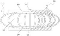
图1示出了根据本发明的椎间融合器的实施例的主视示意图;Figure 1 shows a schematic front view of an embodiment of an interbody cage according to the present invention;
图2示出了图1的椎间融合器的局部剖视示意图;Figure 2 shows a schematic partial cross-sectional view of the interbody cage of Figure 1;
图3示出了图1的椎间融合器的侧视示意图;Figure 3 shows a schematic side view of the cage of Figure 1;
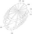
图4示出了图1的椎间融合器的立体结构示意图;Fig. 4 shows a three-dimensional schematic diagram of the interbody cage of Fig. 1;
图5示出了图1的椎间融合器的另一视角的立体结构示意图;FIG. 5 shows a schematic three-dimensional structure diagram of the interbody cage of FIG. 1 from another perspective;
图6示出了图1的椎间融合器的剖视示意图;以及Figure 6 shows a schematic cross-sectional view of the cage of Figure 1; and
图7示出了图1的椎间融合器的仰视示意图。FIG. 7 shows a schematic bottom view of the cage of FIG. 1 .
其中,上述附图包括以下附图标记:Wherein, the above-mentioned drawings include the following reference signs:
10、第一支撑件;20、第二支撑件;30、弹性筋;31、第一弹性筋;32、第二弹性筋;40、硅胶件;50、防滑筋;60、凸刺。10, the first support; 20, the second support; 30, the elastic rib; 31, the first elastic rib; 32, the second elastic rib; 40, the silicone part;
具体实施方式Detailed ways
下面将结合本发明实施例中的附图,对本发明实施例中的技术方案进行清楚、完整地描述,显然,所描述的实施例仅仅是本发明一部分实施例,而不是全部的实施例。以下对至少一个示例性实施例的描述实际上仅仅是说明性的,决不作为对本发明及其应用或使用的任何限制。基于本发明中的实施例,本领域普通技术人员在没有作出创造性劳动前提下所获得的所有其他实施例,都属于本发明保护的范围。The technical solutions in the embodiments of the present invention will be clearly and completely described below with reference to the accompanying drawings in the embodiments of the present invention. Obviously, the described embodiments are only a part of the embodiments of the present invention, but not all of the embodiments. The following description of at least one exemplary embodiment is merely illustrative in nature and is in no way intended to limit the invention, its application, or uses. Based on the embodiments of the present invention, all other embodiments obtained by those of ordinary skill in the art without creative efforts shall fall within the protection scope of the present invention.
需要注意的是,这里所使用的术语仅是为了描述具体实施方式,而非意图限制根据本申请的示例性实施方式。如在这里所使用的,除非上下文另外明确指出,否则单数形式也意图包括复数形式,此外,还应当理解的是,当在本说明书中使用术语“包含”和/或“包括”时,其指明存在特征、步骤、操作、器件、组件和/或它们的组合。It should be noted that the terminology used herein is for the purpose of describing specific embodiments only, and is not intended to limit the exemplary embodiments according to the present application. As used herein, unless the context clearly dictates otherwise, the singular is intended to include the plural as well, furthermore, it is to be understood that when the terms "comprising" and/or "including" are used in this specification, it indicates that There are features, steps, operations, devices, components and/or combinations thereof.
除非另外具体说明,否则在这些实施例中阐述的部件和步骤的相对布置、数字表达式和数值不限制本发明的范围。同时,应当明白,为了便于描述,附图中所示出的各个部分的尺寸并不是按照实际的比例关系绘制的。对于相关领域普通技术人员已知的技术、方法和设备可能不作详细讨论,但在适当情况下,技术、方法和设备应当被视为授权说明书的一部分。在这里示出和讨论的所有示例中,任何具体值应被解释为仅仅是示例性的,而不是作为限制。因此,示例性实施例的其它示例可以具有不同的值。应注意到:相似的标号和字母在下面的附图中表示类似项,因此,一旦某一项在一个附图中被定义,则在随后的附图中不需要对其进行进一步讨论。The relative arrangement of the components and steps, the numerical expressions and numerical values set forth in these embodiments do not limit the scope of the invention unless specifically stated otherwise. Meanwhile, it should be understood that, for the convenience of description, the dimensions of various parts shown in the accompanying drawings are not drawn in an actual proportional relationship. Techniques, methods, and apparatus known to those of ordinary skill in the relevant art may not be discussed in detail, but where appropriate, techniques, methods, and apparatus should be considered part of the authorized description. In all examples shown and discussed herein, any specific value should be construed as illustrative only and not as limiting. Accordingly, other examples of exemplary embodiments may have different values. It should be noted that like numerals and letters refer to like items in the following figures, so once an item is defined in one figure, it does not require further discussion in subsequent figures.
为了提高椎间融合器的复位力,如图1至图5所示,在本实施例中,椎间融合器包括:第一支撑件10、第二支撑件20、多个弹性筋30以及硅胶件40。第二支撑件20设置于第一支撑件10的下方。多个弹性筋30间隔设置于第一支撑件10和第二支撑件20之间。硅胶件40设置于第一支撑件10和第二支撑件20之间。其中,多个弹性筋30中的部分弹性筋30位于硅胶件40的内部,其余的弹性筋30围绕在硅胶件40的外部。In order to improve the restoring force of the intervertebral cage, as shown in FIGS. 1 to 5 , in this embodiment, the intervertebral cage includes: a
应用本实施例的技术方案,多个弹性筋30间隔设置在第一支撑件10和第二支撑件20之间,同时,在第一支撑件10和第二支撑件20之间还设置有硅胶件40。多个弹性筋30中的部分弹性筋30设置在硅胶件40的内部,其余的弹性筋30位于硅胶件40的外部。通过上述的设置,在椎间融合器植入后,弹性筋30和硅胶件40被压缩变形,但是由于弹性筋30和硅胶件40均具有弹性力,因此,弹性筋30和硅胶件40能够对第一支撑件10和第二支撑件20起到支撑的作用,并且硅胶件40能够降低弹性筋30无法复原的可能性。同时,位于硅胶件40外侧的弹性筋30能够对硅胶件40起到限位的作用,使得硅胶件40的位置稳定,不容易从第一支撑件10和第二支撑件20之间脱出。因此本实施例的技术方案有效地解决了相关技术中的弹性筋的形状无法复原进而导致患者的使用效果较差的问题。Applying the technical solution of this embodiment, a plurality of
需要说明的是,上述的多个弹性筋30中的部分弹性筋30位于硅胶件40的内部可以是一个弹性筋30位于硅胶件40的内部,也可以是多个弹性筋30设置在硅胶件40的内部。硅胶件40是通过注塑的方式进行设置的。It should be noted that, some of the
考虑到硅胶件的固定以及椎间融合器的整体的弹性形变的变化量,如图1至图6所示,在本实施例中,弹性筋30为弧形,弹性筋30包括多个第一弹性筋31和多个第二弹性筋32,多个第二弹性筋32位于多个第一弹性筋31的内侧,第二弹性筋32位于硅胶件40的内部,第一弹性筋31围绕在硅胶件40的外部。弧形的弹性筋30便于被压缩,同时,弧形的弹性筋30也容易复位。因此将弹性筋30设置为弧形是为了兼顾压缩性能和复位能力的。第一弹性筋31和第二弹性筋32的设置也是为了进一步提高椎间融合器的弹性复位的能力。Considering the fixation of the silicone piece and the variation of the overall elastic deformation of the intervertebral cage, as shown in FIGS. 1 to 6 , in this embodiment, the
为了避免第一弹性筋相互之间发生干涉,如图1至图6所示,在本实施例中,第一弹性筋31的第一端与第一支撑件10的边缘处连接,第一弹性筋31的第二端对应地连接于第二支撑件20的边缘处,多个第一弹性筋31在第一支撑件10的周向方向上间隔设置。第一弹性筋31设置在第一支撑件10的边缘处,同时第一弹性筋31连接在第二支撑件20的边缘处,这样的设置方式能够有效地将硅胶件40固定在第一支撑件10和第二支撑件20之间。In order to avoid mutual interference between the first elastic ribs, as shown in FIG. 1 to FIG. 6 , in this embodiment, the first end of the first
需要说明的是,上述的对应地是指第一弹性筋31的第一端和第一弹性筋31的第二端是在一条竖直的线上,或者该竖直的线与水平面之间具有锐角夹角,该夹角在75°至90°之间。It should be noted that the above correspondingly means that the first end of the first
如图1至图6所示,在本实施例中,每个第一弹性筋31的一部分凸出于第一支撑件10和第二支撑件20。第一弹性筋31的中部凸出于第一支撑件10和第二支撑件20,这样的设置方式,使得椎间融合器被压缩的时候,第一弹性筋31具有较大的变形的空间,并且多个第一弹性筋31不会发生相互的干涉。As shown in FIGS. 1 to 6 , in this embodiment, a part of each first
需要说明的是,上述的第一支撑件10在水平面上的投影完全遮挡第二支撑件20。It should be noted that the above-mentioned projection of the
为了提高支撑强度和弹性力,如图2和图6所示,在本实施例中,第二弹性筋32连接在第一支撑件10和第二支撑件20之间,多个第二弹性筋32具有多个中心线,多个中心线的至少部分位于同一平面上。多个第二弹性筋32的至少部分多个中心线在同一平面上,这样使得多个第二弹性筋32的弹性力的施力范围在同一个区域内,这样使得支撑的强度更好。在保证椎间融合器发生变形的前提下,能够使得椎间融合器的结构强度较好。In order to improve the support strength and elastic force, as shown in FIG. 2 and FIG. 6 , in this embodiment, the second
如图2和图6所示,在本实施例中,第二弹性筋32设置于第一支撑件10的对称线上,多个第二弹性筋32的多个弯曲度由靠近第一支撑件10的中心位置至靠近第一支撑件10的边缘处逐渐增大。第二弹性筋32设置在第一支撑件10的对称线上,即也位于第二支撑件20的对称线上。这样的设置使得第二弹性筋32能够提高固定位置的支撑强度。相邻的两个第二弹性筋32中靠近第一支撑件10的中心的第二弹性筋32的弯曲度小于远离第二弹性筋32的弯曲度。例如在人体颈椎左右侧弯时,左右方向受到较大的压力,当左侧受到压力压缩,则右侧张起,反之同理。将第二弹性筋32设置在第一支撑件10的左右方向上,这样能够使得椎间融合器具有更好的支撑效果和弹性变形的效果。进而能够使得患者的使用效果更好,同时能够提高椎间融合器的使用寿命。As shown in FIG. 2 and FIG. 6 , in this embodiment, the second
需要说明书的是,椎间融合器的第一支撑件10和第二支撑件20为规则形状,包括矩形、圆形以及椭圆形等。具体地,本实施例的第一支撑件10为椭圆形,其对称线为椭圆形的长轴或者短轴。It should be noted that the
弹性筋30的截面为圆形,弹性筋30的材质为碳纤维。弹性筋的截面为圆形。The cross section of the
在图中未示出的实施例中,弹性筋的截面为多边形或者椭圆形。In the embodiment not shown in the drawings, the cross-section of the elastic rib is polygonal or elliptical.
为了避免椎间融合器植入后产生移动,导致椎间融合器的位置不固定。如图4、图5以及图7所示,在本实施例中,第一支撑件10和第二支撑件20上设置有多个防滑筋50,多个防滑筋50由第一支撑件10和第二支撑件20的中心位置呈放射状设置。防滑筋50的设置使得椎间融合器在植入后,第一支撑件10和第二支撑件20与人体骨结构之间的摩擦力较大,能够有效地使得椎间融合器的位置固定。并且,防滑筋50的结构简单,便于设置。由于椎间融合器在植入后具有多个运动的方向,因此将防滑筋50设置为放射状,这样能够有效地提高多个运动方向的摩擦阻力。进而使得椎间融合器的位置固定,不易松动。In order to avoid the movement of the cage after implantation, the position of the cage is not fixed. As shown in FIG. 4 , FIG. 5 and FIG. 7 , in this embodiment, a plurality of
如图1至图5以及图7所示,在本实施例中,第一支撑件10和第二支撑件20上设置有凸刺60,凸刺60位于第一支撑件10和第二支撑件20的中心位置。凸刺60的设置是为了进一步地提高椎间融合器的防滑性能,提高椎间融合器的稳定性。As shown in FIG. 1 to FIG. 5 and FIG. 7 , in this embodiment, the
如图1至图5所示,在本实施例中,第一支撑件10和第二支撑件20为平直板。平直板的结构便于设置,能够降低加工难度。As shown in FIG. 1 to FIG. 5 , in this embodiment, the
在图中未示出的实施例中,第一支撑件10和第二支撑件20为弧形板。或者第一支撑件为平直板,第二支撑件为弧形板。In an embodiment not shown in the figures, the
在本实施例的技术方案中,第一支撑件10和第二支撑件20能够较好地与上下相邻的肢体融合,进而使得椎间融合器与上下椎体接触更加稳定。弹性筋30的设置为椎间融合器提供了弹性,使得其具有变形的能力。硅胶件40的设置一方面是为了提高弹性力,以使椎间融合器具有较好的弹性力;另一方面能够发挥占位的作用,为弹性筋30提供了保护效果,能够避免弹性筋30收到过大的压力导致其断裂。具体地,弹性筋30的材质为碳纤维,碳纤维材质具有重量轻但承重能力强的特点,这使得椎间融合器兼顾了重量和强度。在第一支撑件10和第二支撑件20上均涂有生物涂层,通过生物涂层,以使椎间融合器能够更好地与上下椎骨连接。In the technical solution of this embodiment, the
在本实施例中,图1至图7均为示意图。图1、图2以及图6中仅示意出部分的第二弹性筋。图3至图5中未示出第二弹性筋。In this embodiment, FIGS. 1 to 7 are schematic diagrams. Only a part of the second elastic rib is shown in FIGS. 1 , 2 and 6 . The second elastic rib is not shown in FIGS. 3 to 5 .
如图1至图7所示,本实施例的技术方案是先将第一支撑件10、第二支撑件20以及弹性筋30连接好并固定。形成一个框架,再通过注塑的方式将硅胶件40注塑到上述框架的内部,这样使得硅胶件40包覆住第二弹性筋32,第一弹性筋31位于硅胶件40的外侧。As shown in FIGS. 1 to 7 , the technical solution of this embodiment is to first connect and fix the
在本发明的描述中,需要理解的是,方位词如“前、后、上、下、左、右”、“横向、竖向、垂直、水平”和“顶、底”等所指示的方位或位置关系通常是基于附图所示的方位或位置关系,仅是为了便于描述本发明和简化描述,在未作相反说明的情况下,这些方位词并不指示和暗示所指的装置或元件必须具有特定的方位或者以特定的方位构造和操作,因此不能理解为对本发明保护范围的限制;方位词“内、外”是指相对于各部件本身的轮廓的内外。In the description of the present invention, it should be understood that the orientations indicated by orientation words such as "front, rear, top, bottom, left, right", "horizontal, vertical, vertical, horizontal" and "top, bottom" etc. Or the positional relationship is usually based on the orientation or positional relationship shown in the drawings, which is only for the convenience of describing the present invention and simplifying the description, and these orientation words do not indicate or imply the indicated device or element unless otherwise stated. It must have a specific orientation or be constructed and operated in a specific orientation, so it cannot be construed as a limitation on the protection scope of the present invention; the orientation words "inside and outside" refer to the inside and outside relative to the outline of each component itself.
为了便于描述,在这里可以使用空间相对术语,如“在……之上”、“在……上方”、“在……上表面”、“上面的”等,用来描述如在图中所示的一个器件或特征与其他器件或特征的空间位置关系。应当理解的是,空间相对术语旨在包含除了器件在图中所描述的方位之外的在使用或操作中的不同方位。例如,如果附图中的器件被倒置,则描述为“在其他器件或构造上方”或“在其他器件或构造之上”的器件之后将被定位为“在其他器件或构造下方”或“在其他器件或构造之下”。因而,示例性术语“在……上方”可以包括“在……上方”和“在……下方”两种方位。该器件也可以其他不同方式定位(旋转90度或处于其他方位),并且对这里所使用的空间相对描述作出相应解释。For ease of description, spatially relative terms, such as "on", "over", "on the surface", "above", etc., may be used herein to describe what is shown in the figures. The spatial positional relationship of one device or feature shown to other devices or features. It should be understood that spatially relative terms are intended to encompass different orientations of the device in use or operation in addition to the orientation depicted in the figures. For example, if the device in the figures is turned over, elements described as "above" or "over" other devices or features would then be oriented "below" or "over" the other devices or features under other devices or constructions". Thus, the exemplary term "above" can encompass both an orientation of "above" and "below." The device may also be otherwise oriented (rotated 90 degrees or at other orientations) and the spatially relative descriptions used herein interpreted accordingly.
此外,需要说明的是,使用“第一”、“第二”等词语来限定零部件,仅仅是为了便于对相应零部件进行区别,如没有另行声明,上述词语并没有特殊含义,因此不能理解为对本发明保护范围的限制。In addition, it should be noted that the use of words such as "first" and "second" to define components is only for the convenience of distinguishing corresponding components. Unless otherwise stated, the above words have no special meaning and therefore cannot be understood to limit the scope of protection of the present invention.
以上所述仅为本发明的优选实施例而已,并不用于限制本发明,对于本领域的技术人员来说,本发明可以有各种更改和变化。凡在本发明的精神和原则之内,所作的任何修改、等同替换、改进等,均应包含在本发明的保护范围之内。The above descriptions are only preferred embodiments of the present invention, and are not intended to limit the present invention. For those skilled in the art, the present invention may have various modifications and changes. Any modification, equivalent replacement, improvement, etc. made within the spirit and principle of the present invention shall be included within the protection scope of the present invention.
Claims (8)
Priority Applications (1)
| Application Number | Priority Date | Filing Date | Title |
|---|---|---|---|
| CN202011290222.3ACN112237499B (en) | 2020-11-17 | 2020-11-17 | Intervertebral fusion device |
Applications Claiming Priority (1)
| Application Number | Priority Date | Filing Date | Title |
|---|---|---|---|
| CN202011290222.3ACN112237499B (en) | 2020-11-17 | 2020-11-17 | Intervertebral fusion device |
Publications (2)
| Publication Number | Publication Date |
|---|---|
| CN112237499A CN112237499A (en) | 2021-01-19 |
| CN112237499Btrue CN112237499B (en) | 2022-06-14 |
Family
ID=74166777
Family Applications (1)
| Application Number | Title | Priority Date | Filing Date |
|---|---|---|---|
| CN202011290222.3AActiveCN112237499B (en) | 2020-11-17 | 2020-11-17 | Intervertebral fusion device |
Country Status (1)
| Country | Link |
|---|---|
| CN (1) | CN112237499B (en) |
Citations (6)
| Publication number | Priority date | Publication date | Assignee | Title |
|---|---|---|---|---|
| US6582466B1 (en)* | 1998-12-11 | 2003-06-24 | Stryker Spine | Intervertebral disc prosthesis with reduced friction |
| US6733532B1 (en)* | 1998-12-11 | 2004-05-11 | Stryker Spine | Intervertebral disc prosthesis with improved mechanical behavior |
| CN1758888A (en)* | 2003-03-24 | 2006-04-12 | 斯恩蒂斯有限公司 | Intervertebral disc prosthesis or intervertebral prosthesis |
| CN1976650A (en)* | 2004-04-22 | 2007-06-06 | 华沙整形外科股份有限公司 | Prosthetic intervertebral disc |
| CN106726022A (en)* | 2017-02-22 | 2017-05-31 | 无锡宝莱福医疗器械有限公司 | A kind of artificial intervertebral disk and its forming method without interface friction |
| CN108836580A (en)* | 2018-07-06 | 2018-11-20 | 北京爱康宜诚医疗器材有限公司 | Artificial intervertebral disk frame body |
Family Cites Families (3)
| Publication number | Priority date | Publication date | Assignee | Title |
|---|---|---|---|---|
| DE102006045108B4 (en)* | 2006-09-21 | 2008-12-18 | Fehling Ag | Disc prosthesis |
| US20090043391A1 (en)* | 2007-08-09 | 2009-02-12 | Spinalmotion, Inc. | Customized Intervertebral Prosthetic Disc with Shock Absorption |
| CN105055056B (en)* | 2015-08-28 | 2017-03-29 | 四川大学华西医院 | Cervical vertebra uncinate vertebral joint fusion cage |
- 2020
- 2020-11-17CNCN202011290222.3Apatent/CN112237499B/enactiveActive
Patent Citations (6)
| Publication number | Priority date | Publication date | Assignee | Title |
|---|---|---|---|---|
| US6582466B1 (en)* | 1998-12-11 | 2003-06-24 | Stryker Spine | Intervertebral disc prosthesis with reduced friction |
| US6733532B1 (en)* | 1998-12-11 | 2004-05-11 | Stryker Spine | Intervertebral disc prosthesis with improved mechanical behavior |
| CN1758888A (en)* | 2003-03-24 | 2006-04-12 | 斯恩蒂斯有限公司 | Intervertebral disc prosthesis or intervertebral prosthesis |
| CN1976650A (en)* | 2004-04-22 | 2007-06-06 | 华沙整形外科股份有限公司 | Prosthetic intervertebral disc |
| CN106726022A (en)* | 2017-02-22 | 2017-05-31 | 无锡宝莱福医疗器械有限公司 | A kind of artificial intervertebral disk and its forming method without interface friction |
| CN108836580A (en)* | 2018-07-06 | 2018-11-20 | 北京爱康宜诚医疗器材有限公司 | Artificial intervertebral disk frame body |
Also Published As
| Publication number | Publication date |
|---|---|
| CN112237499A (en) | 2021-01-19 |
Similar Documents
| Publication | Publication Date | Title |
|---|---|---|
| US6869446B2 (en) | Intervertebral spacer device having a domed arch shaped spring | |
| US10758069B2 (en) | Orthotic device | |
| US7270680B2 (en) | Intervertebral spacer device utilizing a spirally slotted belleville washer having radially extending grooves | |
| WO2015119403A1 (en) | Health pillow capable of body type correction | |
| US20040220671A1 (en) | Intervertebral spacer device utilizing a spirally slotted belleville washer and a rotational mounting | |
| CN101404958A (en) | Intervertebral implants and methods of use | |
| CN110013367B (en) | Intervertebral fusion device with buffer part | |
| US7208014B2 (en) | Intervertebral spacer device utilizing a belleville washer having radially extending grooves | |
| JP2013540478A (en) | Cervical pillow for cervical spine disease treatment | |
| CN106691635B (en) | Calcaneal prosthesis | |
| CN112237499B (en) | Intervertebral fusion device | |
| US20150045835A1 (en) | Spinal Fixing Device | |
| KR101539338B1 (en) | Apparatus for lumbar spinal traction | |
| CN204798066U (en) | Artificial pyramid | |
| WO2017126915A1 (en) | Sleeping pillow that encourages free movement of occiput and flow of cerebrospinal fluid during sleep | |
| CN212814284U (en) | Foot arch supporting sock | |
| KR101813106B1 (en) | the improved detachable backbone support for posture correction | |
| KR20250005266A (en) | Pressure relief and massage tools | |
| CN209285844U (en) | Artificial axis | |
| KR102240788B1 (en) | Waist Cushion Capable of Compensating for Physiological Curvature Deformity of Spine | |
| CN210204253U (en) | Cervical pillow suitable for lying on side and lying on back | |
| CN206761802U (en) | Root bone prosthese | |
| TWI407938B (en) | Artificial vertebral implants | |
| CN216221908U (en) | Lumbar vertebra rehabilitation is with adjustable support | |
| CN205671877U (en) | A kind of pillow with neck pillow and pillow with neck |
Legal Events
| Date | Code | Title | Description |
|---|---|---|---|
| PB01 | Publication | ||
| PB01 | Publication | ||
| SE01 | Entry into force of request for substantive examination | ||
| SE01 | Entry into force of request for substantive examination | ||
| GR01 | Patent grant | ||
| GR01 | Patent grant |