CN112236708B - Optical waveguides for display devices - Google Patents
Optical waveguides for display devicesDownload PDFInfo
- Publication number
- CN112236708B CN112236708BCN201980038213.4ACN201980038213ACN112236708BCN 112236708 BCN112236708 BCN 112236708BCN 201980038213 ACN201980038213 ACN 201980038213ACN 112236708 BCN112236708 BCN 112236708B
- Authority
- CN
- China
- Prior art keywords
- optical
- optical waveguide
- optical filter
- filter
- light
- Prior art date
- Legal status (The legal status is an assumption and is not a legal conclusion. Google has not performed a legal analysis and makes no representation as to the accuracy of the status listed.)
- Active
Links
Images


Classifications
- G—PHYSICS
- G02—OPTICS
- G02B—OPTICAL ELEMENTS, SYSTEMS OR APPARATUS
- G02B27/00—Optical systems or apparatus not provided for by any of the groups G02B1/00 - G02B26/00, G02B30/00
- G02B27/01—Head-up displays
- G02B27/0101—Head-up displays characterised by optical features
- G—PHYSICS
- G02—OPTICS
- G02B—OPTICAL ELEMENTS, SYSTEMS OR APPARATUS
- G02B27/00—Optical systems or apparatus not provided for by any of the groups G02B1/00 - G02B26/00, G02B30/00
- G02B27/0081—Optical systems or apparatus not provided for by any of the groups G02B1/00 - G02B26/00, G02B30/00 with means for altering, e.g. enlarging, the entrance or exit pupil
- B—PERFORMING OPERATIONS; TRANSPORTING
- B60—VEHICLES IN GENERAL
- B60K—ARRANGEMENT OR MOUNTING OF PROPULSION UNITS OR OF TRANSMISSIONS IN VEHICLES; ARRANGEMENT OR MOUNTING OF PLURAL DIVERSE PRIME-MOVERS IN VEHICLES; AUXILIARY DRIVES FOR VEHICLES; INSTRUMENTATION OR DASHBOARDS FOR VEHICLES; ARRANGEMENTS IN CONNECTION WITH COOLING, AIR INTAKE, GAS EXHAUST OR FUEL SUPPLY OF PROPULSION UNITS IN VEHICLES
- B60K35/00—Instruments specially adapted for vehicles; Arrangement of instruments in or on vehicles
- B60K35/10—Input arrangements, i.e. from user to vehicle, associated with vehicle functions or specially adapted therefor
- B—PERFORMING OPERATIONS; TRANSPORTING
- B60—VEHICLES IN GENERAL
- B60K—ARRANGEMENT OR MOUNTING OF PROPULSION UNITS OR OF TRANSMISSIONS IN VEHICLES; ARRANGEMENT OR MOUNTING OF PLURAL DIVERSE PRIME-MOVERS IN VEHICLES; AUXILIARY DRIVES FOR VEHICLES; INSTRUMENTATION OR DASHBOARDS FOR VEHICLES; ARRANGEMENTS IN CONNECTION WITH COOLING, AIR INTAKE, GAS EXHAUST OR FUEL SUPPLY OF PROPULSION UNITS IN VEHICLES
- B60K35/00—Instruments specially adapted for vehicles; Arrangement of instruments in or on vehicles
- B60K35/20—Output arrangements, i.e. from vehicle to user, associated with vehicle functions or specially adapted therefor
- B60K35/21—Output arrangements, i.e. from vehicle to user, associated with vehicle functions or specially adapted therefor using visual output, e.g. blinking lights or matrix displays
- B60K35/22—Display screens
- B—PERFORMING OPERATIONS; TRANSPORTING
- B60—VEHICLES IN GENERAL
- B60K—ARRANGEMENT OR MOUNTING OF PROPULSION UNITS OR OF TRANSMISSIONS IN VEHICLES; ARRANGEMENT OR MOUNTING OF PLURAL DIVERSE PRIME-MOVERS IN VEHICLES; AUXILIARY DRIVES FOR VEHICLES; INSTRUMENTATION OR DASHBOARDS FOR VEHICLES; ARRANGEMENTS IN CONNECTION WITH COOLING, AIR INTAKE, GAS EXHAUST OR FUEL SUPPLY OF PROPULSION UNITS IN VEHICLES
- B60K35/00—Instruments specially adapted for vehicles; Arrangement of instruments in or on vehicles
- B60K35/20—Output arrangements, i.e. from vehicle to user, associated with vehicle functions or specially adapted therefor
- B60K35/21—Output arrangements, i.e. from vehicle to user, associated with vehicle functions or specially adapted therefor using visual output, e.g. blinking lights or matrix displays
- B60K35/23—Head-up displays [HUD]
- B60K35/231—Head-up displays [HUD] characterised by their arrangement or structure for integration into vehicles
- B—PERFORMING OPERATIONS; TRANSPORTING
- B60—VEHICLES IN GENERAL
- B60K—ARRANGEMENT OR MOUNTING OF PROPULSION UNITS OR OF TRANSMISSIONS IN VEHICLES; ARRANGEMENT OR MOUNTING OF PLURAL DIVERSE PRIME-MOVERS IN VEHICLES; AUXILIARY DRIVES FOR VEHICLES; INSTRUMENTATION OR DASHBOARDS FOR VEHICLES; ARRANGEMENTS IN CONNECTION WITH COOLING, AIR INTAKE, GAS EXHAUST OR FUEL SUPPLY OF PROPULSION UNITS IN VEHICLES
- B60K35/00—Instruments specially adapted for vehicles; Arrangement of instruments in or on vehicles
- B60K35/50—Instruments characterised by their means of attachment to or integration in the vehicle
- B—PERFORMING OPERATIONS; TRANSPORTING
- B60—VEHICLES IN GENERAL
- B60K—ARRANGEMENT OR MOUNTING OF PROPULSION UNITS OR OF TRANSMISSIONS IN VEHICLES; ARRANGEMENT OR MOUNTING OF PLURAL DIVERSE PRIME-MOVERS IN VEHICLES; AUXILIARY DRIVES FOR VEHICLES; INSTRUMENTATION OR DASHBOARDS FOR VEHICLES; ARRANGEMENTS IN CONNECTION WITH COOLING, AIR INTAKE, GAS EXHAUST OR FUEL SUPPLY OF PROPULSION UNITS IN VEHICLES
- B60K35/00—Instruments specially adapted for vehicles; Arrangement of instruments in or on vehicles
- B60K35/55—Instruments with parts that can change their shape or position to configure an active screen, e.g. by folding or by rolling
- G—PHYSICS
- G02—OPTICS
- G02B—OPTICAL ELEMENTS, SYSTEMS OR APPARATUS
- G02B5/00—Optical elements other than lenses
- G02B5/20—Filters
- G—PHYSICS
- G02—OPTICS
- G02B—OPTICAL ELEMENTS, SYSTEMS OR APPARATUS
- G02B6/00—Light guides; Structural details of arrangements comprising light guides and other optical elements, e.g. couplings
- G02B6/0001—Light guides; Structural details of arrangements comprising light guides and other optical elements, e.g. couplings specially adapted for lighting devices or systems
- G02B6/0011—Light guides; Structural details of arrangements comprising light guides and other optical elements, e.g. couplings specially adapted for lighting devices or systems the light guides being planar or of plate-like form
- G02B6/0075—Arrangements of multiple light guides
- G02B6/0076—Stacked arrangements of multiple light guides of the same or different cross-sectional area
- B—PERFORMING OPERATIONS; TRANSPORTING
- B60—VEHICLES IN GENERAL
- B60K—ARRANGEMENT OR MOUNTING OF PROPULSION UNITS OR OF TRANSMISSIONS IN VEHICLES; ARRANGEMENT OR MOUNTING OF PLURAL DIVERSE PRIME-MOVERS IN VEHICLES; AUXILIARY DRIVES FOR VEHICLES; INSTRUMENTATION OR DASHBOARDS FOR VEHICLES; ARRANGEMENTS IN CONNECTION WITH COOLING, AIR INTAKE, GAS EXHAUST OR FUEL SUPPLY OF PROPULSION UNITS IN VEHICLES
- B60K2360/00—Indexing scheme associated with groups B60K35/00 or B60K37/00 relating to details of instruments or dashboards
- B60K2360/20—Optical features of instruments
- B60K2360/25—Optical features of instruments using filters
- B—PERFORMING OPERATIONS; TRANSPORTING
- B60—VEHICLES IN GENERAL
- B60K—ARRANGEMENT OR MOUNTING OF PROPULSION UNITS OR OF TRANSMISSIONS IN VEHICLES; ARRANGEMENT OR MOUNTING OF PLURAL DIVERSE PRIME-MOVERS IN VEHICLES; AUXILIARY DRIVES FOR VEHICLES; INSTRUMENTATION OR DASHBOARDS FOR VEHICLES; ARRANGEMENTS IN CONNECTION WITH COOLING, AIR INTAKE, GAS EXHAUST OR FUEL SUPPLY OF PROPULSION UNITS IN VEHICLES
- B60K2360/00—Indexing scheme associated with groups B60K35/00 or B60K37/00 relating to details of instruments or dashboards
- B60K2360/20—Optical features of instruments
- B60K2360/33—Illumination features
- B60K2360/336—Light guides
- G—PHYSICS
- G02—OPTICS
- G02B—OPTICAL ELEMENTS, SYSTEMS OR APPARATUS
- G02B27/00—Optical systems or apparatus not provided for by any of the groups G02B1/00 - G02B26/00, G02B30/00
- G02B27/01—Head-up displays
- G02B27/0101—Head-up displays characterised by optical features
- G02B2027/0112—Head-up displays characterised by optical features comprising device for genereting colour display
Landscapes
- Engineering & Computer Science (AREA)
- Physics & Mathematics (AREA)
- Chemical & Material Sciences (AREA)
- Combustion & Propulsion (AREA)
- Transportation (AREA)
- Mechanical Engineering (AREA)
- General Physics & Mathematics (AREA)
- Optics & Photonics (AREA)
- Instrument Panels (AREA)
- Light Guides In General And Applications Therefor (AREA)
Abstract
Translated fromChinese
Description
Translated fromChinese技术领域technical field
本发明涉及一种用于显示设备的光波导以及一种用于生成虚拟图像的设备,该设备使用这种光波导。The invention relates to an optical waveguide for a display device and a device for generating a virtual image using such an optical waveguide.
背景技术Background technique
也称为HUD的抬头显示器理解成如下显示系统,即,在该显示系统中,观察者可保持其视线方向,因为使待示出的内容渐显到观察者的视野中。虽然这种类型的系统由于其复杂性和成本本来主要使用在航空领域中,但是该系统目前也大量安装在汽车领域中。A heads-up display, also referred to as HUD, is understood to be a display system in which the viewer can maintain his or her viewing direction because the content to be displayed is faded into the viewer's field of view. Although systems of this type are primarily used in the aviation sector due to their complexity and cost, they are also currently installed in large numbers in the automotive sector.
抬头显示器通常由图像生成器、光学单元和镜子单元组成。图像生成器产生图像。光学单元将图像传导到镜子单元上。图像生成器通常也称为成像单元或PGU(图像生成单元)。镜子单元是部分映现的、能透光的玻璃片。因此,观察者作为虚拟图像看到由图像生成器示出的内容,并且同时看到在玻璃片之后的真实世界。在汽车领域中,前挡风玻璃通常用作镜子单元,在显示时,必须考虑前挡风玻璃的弯曲的形状。通过光学单元和镜子单元的共同作用,虚拟图像是由图像生成器产生的图像的放大展示。A heads-up display usually consists of an image generator, an optical unit and a mirror unit. Image generators generate images. The optical unit conducts the image onto the mirror unit. Image generators are also commonly referred to as imaging units or PGUs (Picture Generation Units). The mirror unit is a partially reflected, light-transmitting glass sheet. The observer thus sees, as a virtual image, what is shown by the image generator and at the same time sees the real world behind the pane of glass. In the automotive field, a windshield is generally used as a mirror unit, and when displaying, the curved shape of the windshield must be taken into account. Through the joint action of the optical unit and the mirror unit, the virtual image is an enlarged display of the image generated by the image generator.
观察者仅仅可从所谓的眼动范围(Eyebox)的位置中观察虚拟图像。如下区域被称为眼动范围,即,该区域的高度和宽度相应于理论的视窗。只要观察者的眼睛位于眼动范围之内,则虚拟图像的所有元素对于眼睛来说都是可见的。相反地,如果眼睛位于眼动范围之外,则对于观察者来说,仅仅还能部分地看到或者甚至看不到虚拟图像。由此,眼动范围越大,观察者在选择其座位时的限制越少。The viewer can observe the virtual image only from the position of the so-called eyebox. The range of eye movements is referred to as the region whose height and width correspond to the theoretical viewing window. All elements of the virtual image are visible to the viewer's eyes as long as they are within the eye range. Conversely, if the eye is outside the range of eye movement, the virtual image is still only partially visible or not even visible to the observer. Thus, the greater the eye movement range, the less restricted the observer is when choosing his seat.
传统的抬头显示器的虚拟图像的大小受到光学单元的大小限制。用于放大虚拟图像的方案在于,将来自成像单元的光耦合到光波导中。被耦合到光波导中的载有图像信息的光在光波导的分界面上被完全反射,并且由此在光波导之内被引导。附加地,在沿着传播方向的多个位置上分别使光的一部分退耦,从而通过光波导的面分布地给出图像信息。以这种方式,通过光波导扩大出射光瞳。在此,有效的出射光瞳由图像生成系统的孔径的图像组成。The size of the virtual image of a conventional head-up display is limited by the size of the optical unit. The solution for enlarging the virtual image consists in coupling the light from the imaging unit into the optical waveguide. The image-information-carrying light coupled into the optical waveguide is completely reflected at the interface of the optical waveguide and is thus guided within the optical waveguide. In addition, a part of the light is decoupled in each case at a plurality of positions along the direction of propagation, so that the image information is distributed over the area of the optical waveguide. In this way, the exit pupil is enlarged by the optical waveguide. Here, the effective exit pupil consists of the image of the aperture of the image generating system.
在该背景下,专利文献US 2016/0124223 Al描述了一种用于虚拟图像的显示装置。该显示装置包括光波导,光波导使得来自成像单元的通过第一光射入面射入的光重复地经受内部反射,以便在第一方向上远离第一光射入面运动。此外,光波导引起,在光波导中被引导的光的一部分通过在第一方向上延伸的、第一光射入面的区域向外离开。显示装置此外包括第一光射入侧的衍射光栅和第一光射出侧的衍射光栅,第一光射入侧的衍射光栅使射上的光衍射,以引起被衍射的光进入光波导中,并且第一光射出侧的衍射光栅使从光波导射入的光衍射。In this context, patent document US 2016/0124223 Al describes a display device for virtual images. The display device includes an optical waveguide that causes light incident through the first light incident surface from the imaging unit to repeatedly undergo internal reflection so as to move away from the first light incident surface in a first direction. Furthermore, the optical waveguide has the effect that a part of the light guided in the optical waveguide exits to the outside via the region of the first light entry area extending in the first direction. The display device further comprises a diffraction grating on the first light entrance side and a diffraction grating on the first light exit side, the diffraction grating on the first light entrance side diffracts incident light to cause the diffracted light to enter the optical waveguide, And the diffraction grating on the first light exit side diffracts the light entering from the optical waveguide.
在专利文献US 2016/0124223 Al中使用的光波导在光波长方面进行了优化。如果应显示彩色的虚拟图像,设置两个或多个分别在波长方面优化的部分光波导。在此,通常为每个颜色分配一个部分光波导。但是,也可在一个部分光波导中以组合的方式输送两种颜色。通过光源以相应从属的颜色照射部分光波导。在以全息影像的光波导为基础的抬头显示器中,除了可用光之外,也将日光在相应的部分光波导的玻璃板上的像镜面反射一样的且全息的反射通过镜子单元向眼睛反射。这通常导致至少损害图像感觉,但是常常也导致直接的、安全关键的系统用户的眩目。The optical waveguide used in the patent document US 2016/0124223 Al is optimized with respect to the wavelength of light. If a colored virtual image is to be displayed, two or more partial optical waveguides, each optimized with respect to wavelength, are provided. Here, a partial light guide is usually assigned to each color. However, it is also possible to feed both colors in a combined manner in one partial optical waveguide. Parts of the optical waveguide are illuminated by the light source in correspondingly assigned colors. In head-up displays based on holographic light guides, in addition to the usable light, the mirror-like and holographic reflection of sunlight on the glass panes of the respective partial light guides is reflected towards the eye via the mirror unit. This usually leads to impairment of at least the perception of the image, but often also to blinding of immediate, safety-critical system users.
发明内容Contents of the invention
本发明的目的是,提供一种光波导以及一种用于产生虚拟图像的设备,在其中,减小由于干扰光引起的眩目风险。It is an object of the present invention to provide an optical waveguide and a device for generating virtual images in which the risk of dazzle due to interfering light is reduced.
该目的通过根据本发明的用于显示设备的的光波导并且通过根据本发明的用于产生虚拟图像的设备实现。This object is achieved by an optical waveguide according to the invention for a display device and by a device according to the invention for generating a virtual image.
根据本发明的第一方面,用于显示设备的光波导包括两个或多个与不同的波长相匹配的部分光波导,其中,部分光波导中的至少一个具有光学滤波器。According to a first aspect of the present invention, an optical waveguide for a display device includes two or more partial optical waveguides matched to different wavelengths, wherein at least one of the partial optical waveguides has an optical filter.
根据本发明的另一方面,用于产生虚拟图像的设备具有:According to another aspect of the present invention, a device for generating a virtual image has:
-用于产生图像的成像单元;- an imaging unit for producing an image;
-用于将图像投影到镜子单元/反射单元上以产生虚拟图像的光学单元;及- an optical unit for projecting an image onto a mirror unit/reflection unit to generate a virtual image; and
-用于扩大出射光瞳/出瞳直径的根据本发明的光波导。- An optical waveguide according to the invention for enlarging the exit pupil/exit pupil diameter.
在使用激光时,仅仅将非常窄带的谱用于光源的基础波长。通过使用与所用的波长相匹配的合适的光学滤波器实现,仅仅干扰光的该窄带的波长范围可传播到部分光波导。这显著减少了潜在被反射的太阳光的份额,因为仅仅太阳光的其波长位于光学滤波器的传输范围中的组成部分可进入部分光波导中。由此,实现将回反射减少到在传输中所需的光学滤波器的透明度的最小值上。When using lasers, only a very narrow-band spectrum is used for the fundamental wavelength of the light source. By using suitable optical filters matched to the wavelengths used, only this narrow wavelength range of the interfering light can be propagated to part of the optical waveguide. This significantly reduces the proportion of potentially reflected sunlight, since only those components of the sunlight whose wavelength lies in the transmission range of the optical filter can enter the partial optical waveguide. This achieves a reduction of back reflections to the minimum values required for the transparency of the optical filter during transmission.
根据本发明的光波导实现,实现具有更少的由于干扰光引起的眩目的抬头显示器。因此,尤其有利的是使用在如下抬头显示器中,该抬头显示器使用在其中存在太阳光可能耦合到光波导中的环境中。例如在机动车中的应用中是这种情况。The optical waveguide implementation according to the invention enables a head-up display with less glare due to interfering light. It is therefore particularly advantageous to use in head-up displays which are used in environments where there is a possibility of coupling of sunlight into the optical waveguide. This is the case, for example, in applications in motor vehicles.
根据本发明的一个方面,光学滤波器是介电的滤波器。介电的滤波器具有的优点是,可非常准确地调整传输性能,并且可实现非常窄带的传输带。同时,在市场上有大量可在没有成本增加的情况下使用的合适的介电的滤波器。According to one aspect of the invention, the optical filter is a dielectric filter. Dielectric filters have the advantage that the transmission properties can be adjusted very precisely and very narrow transmission bands can be achieved. At the same time, there are a large number of suitable dielectric filters available on the market without increased costs.
根据本发明的一个方面,光波导具有用于三个对应的波长的三个部分光波导。以这种方式,光波导可用于显示多色的虚拟图像。例如,可为红色、绿色和蓝色优化部分光波导,利用这些颜色可示出全色的图像。对于本领域技术人员来说,已知其它可实现全色图像的颜色组合。According to one aspect of the invention, the optical waveguide has three partial optical waveguides for three corresponding wavelengths. In this way, optical waveguides can be used to display multicolored virtual images. For example, parts of the light guide can be optimized for red, green, and blue, with which a full-color image can be shown. Other color combinations to achieve full color images are known to those skilled in the art.
根据本发明的一个方面,第一光部分波导具有能透过三种波长的光学滤波器。第二部分光波导具有能透过三种波长中的两种的光学滤波器。第三部分光波导仅仅具有能透过三种波长中的一种的光学滤波器。根据该实施方式,对于每个部分光波导存在一个光学滤波器。从干扰光源的角度的第一部分光波导在上侧具有能透过所有三种颜色的第一光学滤波器,而随后的部分光波导的第二光学滤波器仅仅还能透过两种颜色。第三部分光波导的第三光学滤波器仅仅还能透过一种颜色。以这种方式,可进一步减小潜在被反射的太阳光的份额。According to an aspect of the present invention, the first light section waveguide has an optical filter that transmits three wavelengths. The second part of the optical waveguide has an optical filter that is transparent to two of the three wavelengths. The third part of the optical waveguide has an optical filter that transmits only one of the three wavelengths. According to this embodiment, there is one optical filter for each partial optical waveguide. The first part of the optical waveguide from the point of view of the interfering light source has a first optical filter on the upper side which is transparent to all three colors, whereas the second optical filter of the subsequent part of the optical waveguide is also transparent to only two colors. The third optical filter of the third part of the optical waveguide is only able to transmit one color. In this way, the share of potentially reflected sunlight can be further reduced.
根据本发明的一个方面,部分光波导构造成扁平的并且形成堆垛。通过部分光波导的扁平的实施方案,光波导可用于在两个尺寸中扩大出射光瞳。在此,部分光波导集成在堆垛中简化了在组装抬头显示器期间的操作和调整。由此,同时实现光波导的更高的稳定性,这尤其是对于暴露在例如由于在行驶期间在机动车中出现的震动引起的外力作用下的抬头显示器是重要的。According to one aspect of the invention, the partial optical waveguides are designed flat and form a stack. By means of a flat embodiment of part of the optical waveguide, the optical waveguide can be used to enlarge the exit pupil in two dimensions. In this case, the integration of parts of the optical waveguide in the stack simplifies handling and adjustment during assembly of the head-up display. This simultaneously achieves a higher stability of the optical waveguide, which is particularly important for head-up displays that are exposed to external forces, for example due to vibrations that occur in a motor vehicle while driving.
根据本发明的一个方面,至少一个光学滤波器集成在堆垛中。通过将光学滤波器集成在堆垛中,在一定程度上保护光学滤波器不受外部影响。此外,在该实施方案中,光波导可与光学滤波器一起在唯一的生产步骤中安装在抬头显示器中,由此缩短了制造时间。According to one aspect of the invention, at least one optical filter is integrated in the stack. By integrating the optical filter in the stack, the optical filter is protected to a certain extent from external influences. Furthermore, in this embodiment, the optical waveguide together with the optical filter can be installed in the head-up display in a single production step, thereby reducing the manufacturing time.
根据本发明的一个方面,光学滤波器被施加到部分光波导的分界面上。以这种方式,可避免在堆垛中的继续反射,并且将由入射到所有分界面的干扰光输送的能量的量最小化。According to one aspect of the invention, an optical filter is applied to the interface of part of the optical waveguide. In this way, further reflections in the stack can be avoided and the amount of energy delivered by interfering light incident on all interfaces is minimized.
根据本发明的一个方面,通过蒸镀或喷涂将光学滤波器施加到部分光波导的分界面上。通过蒸镀,也就是说通过层的汽相渗镀,可非常成本适宜地制造期望的光学滤波器。通过喷涂(也称为阴极溅射)施加光学滤波器虽然成本更适宜,但是尤其适合用于高的精度要求的复杂的滤波器。According to one aspect of the invention, the optical filter is applied to the interface of the part of the optical waveguide by evaporation or spraying. The desired optical filter can be produced very cost-effectively by evaporation, that is to say by vapor deposition of layers. Although the application of optical filters by spraying (also known as sputtering) is more cost-effective, it is especially suitable for complex filters with high precision requirements.
优选地,根据本发明设备用于在交通工具中产生虚拟图像,以用于为交通工具的操作者产生虚拟图像。交通工具例如可为机动车或飞机。显然,根据本发明的解决方案也可使用在其它环境中或用于其它应用,例如使用在载重货车,轨道技术和公共交通系统中,在起重机和建筑机械中等。Preferably, the device according to the invention is used for generating a virtual image in a vehicle for generating a virtual image for an operator of the vehicle. The vehicle may be, for example, a motor vehicle or an airplane. Obviously, the solution according to the invention can also be used in other environments or for other applications, for example in trucks, rail technology and public transport systems, in cranes and construction machines, etc.
附图说明Description of drawings
从以下描述和所附的权利要求中结合附图可得到本发明的其它特征。Other characteristics of the invention emerge from the following description and appended claims when taken in conjunction with the accompanying drawings.
其中in
图1示意性地示出了根据现有技术的用于机动车的抬头显示器;FIG. 1 schematically shows a head-up display for a motor vehicle according to the prior art;
图2示出了二维放大的光波导;Figure 2 shows a magnified optical waveguide in two dimensions;
图3示意性地示出了具有光波导的抬头显示器;Figure 3 schematically shows a heads-up display with an optical waveguide;
图4示意性地示出了在机动车中的具有光波导的抬头显示器;FIG. 4 schematically shows a head-up display with an optical waveguide in a motor vehicle;
图5示出了干扰光射入根据本发明的具有光学滤波器的光波导中;Fig. 5 shows that disturbing light is injected into an optical waveguide with an optical filter according to the present invention;
图6示意性地示出了图5中的光学滤波器的传输曲线;Fig. 6 schematically shows the transmission curve of the optical filter in Fig. 5;
图7示出了干扰光射入根据本发明的具有三个光学滤波器的光波导中;以及Fig. 7 shows that disturbance light is injected into an optical waveguide with three optical filters according to the present invention; and
图8示意性地示出了图7中的光学滤波器的传输曲线。FIG. 8 schematically shows the transmission curve of the optical filter in FIG. 7 .
具体实施方式Detailed ways
为了更好地理解本发明的原理,接下来根据附图更详细地解释本发明的实施方式。在图中,相同的附图标记用于相同的或功能相同的元件,并且不需要针对每个附图重新描述。可理解的是,本发明不限制在所示出的实施方式上,并且所描述的特征也可组合或修改,只要不离开例如在所附的权利要求中定义的本发明的保护范围。In order to better understand the principle of the present invention, the implementation of the present invention will be explained in more detail with reference to the accompanying drawings. In the figures, the same reference numerals are used for the same or functionally identical elements, and a new description is not required for each figure. It is understood that the invention is not limited to the embodiments shown and that the described features can also be combined or modified without departing from the scope of protection of the invention as defined, for example, in the appended claims.
首先,应根据图1至4阐述具有光波导的抬头显示器的基本构思。First, the basic concept of a head-up display with an optical waveguide shall be explained on the basis of FIGS. 1 to 4 .
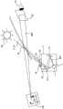
图1示出了根据现有技术的用于机动车的抬头显示器的原理图。抬头显示器具有图像生成器1、光学单元2和镜子单元3。射线束SB1从显示元件11中离开,射线束由折叠镜21反射到弯曲的镜子22上,弯曲的镜子将射线束反射向镜子单元3的方向。镜子单元3在此作为机动车的前挡风玻璃31示出。射线束SB2从该处到达观察者的眼睛61的方向。FIG. 1 shows a schematic diagram of a head-up display for a motor vehicle according to the prior art. The head-up display has an
观察者看到位于机动车之外在发动机罩上方的或者甚至位于机动车前方的虚拟图像VB。通过光学单元2和镜子单元3的共同作用,虚拟图像VB是由显示元件11显示的图像的放大图。在此,以符号示出了限速、当前的车辆速度以及导航指示。只要眼睛61位于通过矩形指出的眼动范围62之内,则虚拟图像的所有元素对于眼睛61来说是可见的。如果眼睛61位于眼动范围62之外,则虚拟图像VB对于观察者来说仅仅部分可见或者甚至不可见。眼动范围62越大,观察者在选择其座位时的限制越少。The observer sees a virtual image VB located outside the motor vehicle above the bonnet or even in front of the motor vehicle. Through the cooperation of the
弯曲的镜子22的曲率与前挡风玻璃31的曲率相匹配并且确保,图像畸变在整个眼动范围22上是稳定的。弯曲的镜子22借助于支承部221可旋转地支承。由此实现的弯曲的镜子22的旋转实现眼动范围22的移动以及由此眼动范围22的位置与眼睛61的位置的匹配。折叠镜21用于,由射线束SB1经过的在显示元件11和弯曲的镜子22之间的路程长,并且同时光学单元2尽可能紧凑。通过透明的覆盖部23将光学单元2与环境分隔。由此,例如保护光学单元2的光学元件以防位于车辆的内部中的灰尘影响。此外,在覆盖部23上存在光学的薄膜或偏光器24。显示元件11典型地进行偏振,并且镜子单元3像模拟器那样作用。因此,偏光器24的目的是,影响偏振,以实现可用光的均匀的可见性。眩目保护部25用于,可靠地吸收通过覆盖部23的分界面反射的光,从而不引起观察者的眩目。除了太阳光SL,另一干扰光源64的光也可到达显示元件11上。与偏振滤波器组合,偏光器24附加地也可用于隐没射入的太阳光SL。The curvature of the
图2以示意性的空间图示出了二维尺寸放大的光波导5。在左下的区域中,可看到耦合全息图(hologramm)53,借助于耦合全息图将来自未示出的成像单元的光L1耦合到光波导5中。在光波导中,光L1在图中相应于箭头L2向右上扩散。在光波导5的该区域中,存在折叠全息图51,折叠全息图与多个先后布置的部分透过的镜子相似地作用,并且产生在Y方向上变宽的、在X方向上传播的光束。这通过三个箭头L3指出。在图中向右延伸的光波导5的部分中存在退耦全息图52,退耦全息图同样与多个先后布置的部分透过的镜子相似地作用,并且通过箭头L4指出的光在Z方向上向上从光波导5中退耦。在此,在X方向上传播,从而原来的射入的光束L1作为在两个尺寸中放大的光束L4离开光波导5。FIG. 2 shows a two-dimensionally enlarged
图3以空间图示出了具有三个光波导5R、5G、5B的抬头显示器,光波导彼此上下布置并且分别代表基本色红、绿和蓝。光波导5R、5G、5B共同形成光波导5。在光波导5中存在的全息图51、52、53与波长相关,从而光波导5R、5G、5B分别用于基本色。在光波导5之上示出了图像发生器1和光学单元2。光学单元2具有镜子20,借助于镜子使由图像发生器1产生的且由光学单元2形成的光转向相应的耦合全息图53的方向。图像发生器1具有三个用于三个基本色的光源14R、14G、14B。可看出,整个所示出的单元具有与其射出光的面相比小的总高度。FIG. 3 shows a head-up display in a spatial diagram with three
图4示出了与图1相似的在机动车中的抬头显示器,然而在此以空间图示出并且同时示出了光波导5。可看出示意性地示出的图像发生器1,图像发生器产生平行的射线束SB1,射线束借助于镜子平面523耦合到光波导5中。为简单起见,未示出光学单元。多个镜子平面522分别将射到镜子平面上的光的一部分反射向前挡风玻璃31、镜子单元3的方向。由镜子3将光反射向眼睛61的方向。观察者在发动机罩上方或在机动车前方更远的距离中看到虚拟图像VB。在该技术中,整个光学系统也安装在壳体中,即,由透明的覆盖部与环境分隔开。如在图1中的抬头显示器中那样,在该覆盖部上可布置阻化剂。FIG. 4 shows a head-up display in a motor vehicle similar to FIG. 1 , but here in a spatial diagram and simultaneously with an
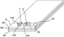
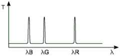
图5示出了干扰光射入具有光学滤波器70的根据本发明的光波导5中。图6示意性地示出了光学滤波器70的传输曲线。光波导5是用于为观察者61产生虚拟图像VB的设备的组成部分。在该示例中,设备是机动车的抬头显示器。在此,光波导5用于二维地扩大出射光瞳。机动车的前挡风玻璃31用作镜子单元3。在此,干扰光源64是太阳。FIG. 5 shows the incidence of disturbance light into an
在所示出的实施例中,光波导5具有三个为不同的波长λR、λG、λB优化的部分光波导5R、5G、5B。优选地,波长相应于红色、绿色和蓝色。在图5中最上方的部分光波导5R具有光学滤波器70,例如以介电滤波器的形式。如可从图6中的示意性的传输曲线(在其中相对于波长λ示出了传输系数T)中得到的那样,光学滤波器70具有三个窄带的传输带,传输带相应于三个所用的波长λR、λG、λB。部分光波导5R、5G、5B通过光源14R、14G、14B照射,光源分别射出从属的颜色。在使用激光时,仅仅存在用于光源14R、14G、14B的基础波长λR、λG、λB的窄带的谱。In the exemplary embodiment shown, the
在以全息影像的光波导5为基础的抬头显示器中,除了可用光之外,也将作为干扰光源64的太阳在相应的部分光波导5R、5G、5B的玻璃板上像镜面反射一样的且全息的反射通过镜子单元3向眼睛61反射。这通常至少导致损害图像感觉,但是常常也导致直接的、安全关键的系统用户的眩目。通过使用光学滤波器70实现,仅仅干扰光的窄带的区域可传播到部分光波导5R、5G、5B。这显著减小了潜在被反射的太阳光的份额。In the head-up display based on the
图7示出了干扰光射入具有三个光学滤波器70R、70G、70B的根据本发明的光波导5中。图8示意性地示出了光学滤波器70R、70G、70B的传输曲线。在此,部分图(a)示出了从第一光学滤波器70R的干扰光源64的方面的传输曲线,部分图(b)示出了第二光学滤波器70G的传输曲线,并且部分图(c)示出了第三光学滤波器70G的传输曲线。如已经在图6中那样,在传输曲线中相对于波长λ示出了传输系数T。FIG. 7 shows the incidence of disturbance light into an
在该变型方案中,对于每个部分光波导5R、5G、5B存在光学滤波器70R、70G、70B。从干扰光源64方面的第一部分光波导5R在上侧上具有能透过所有三种颜色的第一光学滤波器70R,而随后的部分光波导5G的第二光学滤波器70G仅仅还能透过两种颜色。第三部分光波导5B的第三光学滤波器70B仅仅还能透过一种颜色。根据制造过程的方案,光学滤波器70R、70G、70B也可直接施加到部分光波导5R、5G、5B的分界面上,以避免继续反射,并且将到达所有分界面的能量的量最小化。In this variant, there is an
附图标记清单list of reference signs
1 图像发生器/成像单元1 Image generator/imaging unit
11 显示单元11 Display unit
14、14R、14G、14B 光源14, 14R, 14G, 14B light source
2 光学单元2 optical unit
20 镜子20 mirrors
21 折叠镜21 folding mirror
22 弯曲的镜子22 curved mirror
221 支承部221 Support part
23 透明的覆盖部23 transparent cover
24 光学的薄膜/偏光器24 Optical films/polarizers
25 眩目保护部25 Dazzling Protection Department
3 镜子单元3 mirror units
31 前挡风玻璃31 Front windshield
5、5R、5G、5B 光波导5, 5R, 5G, 5B optical waveguide
51 折叠全息图51 Folded Holograms
52 退耦全息图52 Decoupling Holograms
522 镜子平面522 mirror plane
523 镜子平面523 mirror plane
53 耦合全息图53 Coupling Holograms
54 基质54 matrix
55 覆盖层55 Overlays
56 全息图层56 holographic layers
61 眼睛/观察者61 Eyes/Observers
62 眼动范围62 Eye range
64 干扰光源64 Interfering Light Sources
70、70R、70G、70B 光学滤波器70, 70R, 70G, 70B Optical Filters
L1…L4 光L1…L4 light
λ、λR、λG、λB 波长λ, λR, λG, λB wavelengths
S1 接收待显示的图像S1 receives the image to be displayed
S2 确定没有待示出的图像内容的区域S2 Determining areas with no image content to be shown
S3 相应于确定的区域切换电极阵列S3 switches the electrode array corresponding to the defined area
SB1、SB2 射线束SB1, SB2 beams
SL 太阳光SL Sunlight
T 传输系统T transmission system
VB 虚拟图像VB virtual image
Claims (8)
Applications Claiming Priority (3)
| Application Number | Priority Date | Filing Date | Title |
|---|---|---|---|
| DE102018209622 | 2018-06-15 | ||
| DE102018209622.8 | 2018-06-15 | ||
| PCT/EP2019/065498WO2019238823A1 (en) | 2018-06-15 | 2019-06-13 | Optical waveguide for a display device |
Publications (2)
| Publication Number | Publication Date |
|---|---|
| CN112236708A CN112236708A (en) | 2021-01-15 |
| CN112236708Btrue CN112236708B (en) | 2023-07-14 |
Family
ID=66951927
Family Applications (1)
| Application Number | Title | Priority Date | Filing Date |
|---|---|---|---|
| CN201980038213.4AActiveCN112236708B (en) | 2018-06-15 | 2019-06-13 | Optical waveguides for display devices |
Country Status (5)
| Country | Link |
|---|---|
| US (1) | US20210096364A1 (en) |
| EP (1) | EP3807695B1 (en) |
| JP (1) | JP7114748B2 (en) |
| CN (1) | CN112236708B (en) |
| WO (1) | WO2019238823A1 (en) |
Families Citing this family (6)
| Publication number | Priority date | Publication date | Assignee | Title |
|---|---|---|---|---|
| WO2022171031A1 (en)* | 2021-02-10 | 2022-08-18 | 未来(北京)黑科技有限公司 | Display apparatus, head-up display, and transportation device |
| CN115903222A (en)* | 2021-08-05 | 2023-04-04 | 苏州苏大维格科技集团股份有限公司 | Augmented reality head-up display device, vehicle and preparation method of optical waveguide |
| CN118974633A (en) | 2022-03-29 | 2024-11-15 | 富士胶片株式会社 | Virtual image display device |
| WO2024068639A1 (en)* | 2022-09-30 | 2024-04-04 | Carl Zeiss Jena Gmbh | Stray light filter for holographic huds |
| WO2024068642A1 (en)* | 2022-09-30 | 2024-04-04 | Carl Zeiss Jena Gmbh | Minimising glare reflections in a hud by means of targeted reflection reduction |
| WO2024232334A1 (en)* | 2023-05-09 | 2024-11-14 | 富士フイルム株式会社 | Projector and head-up display system |
Citations (1)
| Publication number | Priority date | Publication date | Assignee | Title |
|---|---|---|---|---|
| WO2018036834A1 (en)* | 2016-08-26 | 2018-03-01 | Carl Zeiss Jena Gmbh | Waveguide and devices for data reflection |
Family Cites Families (27)
| Publication number | Priority date | Publication date | Assignee | Title |
|---|---|---|---|---|
| US4693544A (en)* | 1982-12-14 | 1987-09-15 | Nippon Sheet Glass Co., Ltd. | Optical branching device with internal waveguide |
| US4763990A (en)* | 1984-02-03 | 1988-08-16 | Flight Dynamics, Inc. | Head up display system |
| US20040108971A1 (en)* | 1998-04-09 | 2004-06-10 | Digilens, Inc. | Method of and apparatus for viewing an image |
| JP2005234134A (en) | 2004-02-18 | 2005-09-02 | Sony Corp | Backlight light source device for liquid crystal display, and color liquid crystal display |
| US7206107B2 (en)* | 2004-12-13 | 2007-04-17 | Nokia Corporation | Method and system for beam expansion in a display device |
| DE102007042559A1 (en)* | 2007-09-07 | 2009-03-12 | Continental Automotive Gmbh | Fuel delivery unit |
| GB2472444B (en)* | 2009-08-07 | 2014-08-06 | Light Blue Optics Ltd | Head up displays |
| JP5333943B2 (en) | 2010-03-04 | 2013-11-06 | 日本精機株式会社 | Display device |
| JP5622313B2 (en)* | 2010-09-03 | 2014-11-12 | 矢崎総業株式会社 | Head-up display |
| CN203149234U (en)* | 2013-01-04 | 2013-08-21 | 王大量 | Aviation helmet safety goggles and aviation helmet |
| US9243761B2 (en)* | 2013-02-28 | 2016-01-26 | Sumitomo Electric Industries, Ltd. | Optical assembly and method for assembling the same, and optical module implemented with optical assembly |
| CN103777353B (en)* | 2014-01-23 | 2016-08-17 | 深圳点石创新科技有限公司 | A kind of automobile head-up display device |
| JP6269293B2 (en)* | 2014-04-24 | 2018-01-31 | 株式会社デンソー | Head-up display device |
| DE102014214946A1 (en)* | 2014-07-30 | 2016-02-04 | Robert Bosch Gmbh | Display device for a particular motor vehicle and method for operating such a display device |
| US20160077338A1 (en)* | 2014-09-16 | 2016-03-17 | Steven John Robbins | Compact Projection Light Engine For A Diffractive Waveguide Display |
| JP6842418B2 (en)* | 2014-09-22 | 2021-03-17 | イッサム リサーチ ディベロップメント カンパニー オブ ザ ヘブライ ユニバーシティー オブ エルサレム リミテッドYissum Research Development Company Of The Hebrew University Of Jerusalem Ltd. | LC-based optical display system |
| CN112925100B (en) | 2014-09-29 | 2023-10-31 | 奇跃公司 | Optical system |
| DE202014008103U1 (en)* | 2014-10-09 | 2014-12-01 | Oliver Smie | Optical polarization attenuation filter for solar observation in white light |
| JP2016085430A (en) | 2014-10-29 | 2016-05-19 | セイコーエプソン株式会社 | Virtual image display device |
| CN113759555B (en)* | 2015-10-05 | 2024-09-20 | 迪吉伦斯公司 | Waveguide Display |
| DE102016225718B4 (en)* | 2015-12-29 | 2021-12-23 | Ford Global Technologies, Llc | Head-up display for a vehicle as well as a vehicle |
| CN108885310B (en)* | 2016-01-06 | 2020-10-23 | 伊奎蒂公司 | Dual channel imaging light guide with dichroic reflector |
| US9720237B1 (en) | 2016-01-27 | 2017-08-01 | Microsoft Technology Licensing, Llc. | Mixed environment display device and waveguide cross-coupling suppressors |
| US9891436B2 (en)* | 2016-02-11 | 2018-02-13 | Microsoft Technology Licensing, Llc | Waveguide-based displays with anti-reflective and highly-reflective coating |
| US10845591B2 (en)* | 2016-04-12 | 2020-11-24 | Ostendo Technologies, Inc. | Split exit pupil heads-up display systems and methods |
| CN106338832A (en)* | 2016-11-09 | 2017-01-18 | 苏州苏大维格光电科技股份有限公司 | Single holographic diffraction optical waveguide lens and 3D display device |
| US10371896B2 (en)* | 2016-12-22 | 2019-08-06 | Magic Leap, Inc. | Color separation in planar waveguides using dichroic filters |
- 2019
- 2019-06-13EPEP19731667.2Apatent/EP3807695B1/enactiveActive
- 2019-06-13WOPCT/EP2019/065498patent/WO2019238823A1/ennot_activeCeased
- 2019-06-13CNCN201980038213.4Apatent/CN112236708B/enactiveActive
- 2019-06-13JPJP2020569814Apatent/JP7114748B2/enactiveActive
- 2020
- 2020-12-14USUS17/121,202patent/US20210096364A1/enactivePending
Patent Citations (1)
| Publication number | Priority date | Publication date | Assignee | Title |
|---|---|---|---|---|
| WO2018036834A1 (en)* | 2016-08-26 | 2018-03-01 | Carl Zeiss Jena Gmbh | Waveguide and devices for data reflection |
Also Published As
| Publication number | Publication date |
|---|---|
| WO2019238823A1 (en) | 2019-12-19 |
| US20210096364A1 (en) | 2021-04-01 |
| CN112236708A (en) | 2021-01-15 |
| JP2021528681A (en) | 2021-10-21 |
| EP3807695A1 (en) | 2021-04-21 |
| JP7114748B2 (en) | 2022-08-08 |
| EP3807695B1 (en) | 2024-04-24 |
Similar Documents
| Publication | Publication Date | Title |
|---|---|---|
| CN112236708B (en) | Optical waveguides for display devices | |
| CN112272789B (en) | Device for generating virtual images with variable projection distance | |
| US12344093B2 (en) | Vehicle head-up display (HUD) | |
| CN103140791B (en) | The vehicle of perspective display device and lift-launch perspective display device | |
| KR100300102B1 (en) | Device for displaying the first image on the second image seen through the transparent sheet | |
| US20230341680A1 (en) | Apparatus for generating a virtual image, comprising an adjustment mechanism for antireflective slats | |
| WO2020183844A1 (en) | Head-up display device | |
| CN115145039A (en) | Method and device for projecting data by means of a holographic optical element | |
| KR20230152040A (en) | Wavefront control device for head-up display equipped with holographic element, optical device and head-up display | |
| CN103534632A (en) | HUD with holographic optics | |
| CN112236714A (en) | Optical waveguides for display devices | |
| US11287652B2 (en) | Apparatus for generating a virtual image with interference light suppression | |
| CN112219151A (en) | Device for generating virtual images with apertures associated with field points | |
| JP7293259B2 (en) | Optical waveguide for display devices | |
| CN112444995A (en) | Display device for vehicle | |
| JPH06167671A (en) | Display system using hologram | |
| JP7639236B2 (en) | Thin plate structure, method for manufacturing thin plate structure, and cover assembly having thin plate structure | |
| US20240377632A1 (en) | Projector-Based HUD for a Vehicle Having An Increase In Contrast and Efficiency Via a Circular Polarizer | |
| RU2057352C1 (en) | Holographic optical system for information display | |
| KR20240153999A (en) | Wavefront manipulator with total reflection and reflection holograms | |
| WO2025089185A1 (en) | Image projection device | |
| JPH05201271A (en) | Head-up display for vehicle | |
| CN117950187A (en) | Display device with optical waveguide |
Legal Events
| Date | Code | Title | Description |
|---|---|---|---|
| PB01 | Publication | ||
| PB01 | Publication | ||
| SE01 | Entry into force of request for substantive examination | ||
| SE01 | Entry into force of request for substantive examination | ||
| TA01 | Transfer of patent application right | ||
| TA01 | Transfer of patent application right | Effective date of registration:20230203 Address after:Hannover Applicant after:Continental Automotive Technology Co.,Ltd. Address before:Hannover Applicant before:CONTINENTAL AUTOMOTIVE GmbH | |
| GR01 | Patent grant | ||
| GR01 | Patent grant |