CN112236186B - Push Sheath Style - Google Patents
Push Sheath StyleDownload PDFInfo
- Publication number
- CN112236186B CN112236186BCN201980036748.8ACN201980036748ACN112236186BCN 112236186 BCN112236186 BCN 112236186BCN 201980036748 ACN201980036748 ACN 201980036748ACN 112236186 BCN112236186 BCN 112236186B
- Authority
- CN
- China
- Prior art keywords
- expandable
- sheath
- rings
- expanded state
- support structure
- Prior art date
- Legal status (The legal status is an assumption and is not a legal conclusion. Google has not performed a legal analysis and makes no representation as to the accuracy of the status listed.)
- Active
Links
Images


Classifications
- A—HUMAN NECESSITIES
- A61—MEDICAL OR VETERINARY SCIENCE; HYGIENE
- A61M—DEVICES FOR INTRODUCING MEDIA INTO, OR ONTO, THE BODY; DEVICES FOR TRANSDUCING BODY MEDIA OR FOR TAKING MEDIA FROM THE BODY; DEVICES FOR PRODUCING OR ENDING SLEEP OR STUPOR
- A61M25/00—Catheters; Hollow probes
- A61M25/0021—Catheters; Hollow probes characterised by the form of the tubing
- A61M25/0023—Catheters; Hollow probes characterised by the form of the tubing by the form of the lumen, e.g. cross-section, variable diameter
- A—HUMAN NECESSITIES
- A61—MEDICAL OR VETERINARY SCIENCE; HYGIENE
- A61F—FILTERS IMPLANTABLE INTO BLOOD VESSELS; PROSTHESES; DEVICES PROVIDING PATENCY TO, OR PREVENTING COLLAPSING OF, TUBULAR STRUCTURES OF THE BODY, e.g. STENTS; ORTHOPAEDIC, NURSING OR CONTRACEPTIVE DEVICES; FOMENTATION; TREATMENT OR PROTECTION OF EYES OR EARS; BANDAGES, DRESSINGS OR ABSORBENT PADS; FIRST-AID KITS
- A61F2/00—Filters implantable into blood vessels; Prostheses, i.e. artificial substitutes or replacements for parts of the body; Appliances for connecting them with the body; Devices providing patency to, or preventing collapsing of, tubular structures of the body, e.g. stents
- A61F2/02—Prostheses implantable into the body
- A61F2/24—Heart valves ; Vascular valves, e.g. venous valves; Heart implants, e.g. passive devices for improving the function of the native valve or the heart muscle; Transmyocardial revascularisation [TMR] devices; Valves implantable in the body
- A61F2/2427—Devices for manipulating or deploying heart valves during implantation
- A61F2/2436—Deployment by retracting a sheath
- A—HUMAN NECESSITIES
- A61—MEDICAL OR VETERINARY SCIENCE; HYGIENE
- A61F—FILTERS IMPLANTABLE INTO BLOOD VESSELS; PROSTHESES; DEVICES PROVIDING PATENCY TO, OR PREVENTING COLLAPSING OF, TUBULAR STRUCTURES OF THE BODY, e.g. STENTS; ORTHOPAEDIC, NURSING OR CONTRACEPTIVE DEVICES; FOMENTATION; TREATMENT OR PROTECTION OF EYES OR EARS; BANDAGES, DRESSINGS OR ABSORBENT PADS; FIRST-AID KITS
- A61F2/00—Filters implantable into blood vessels; Prostheses, i.e. artificial substitutes or replacements for parts of the body; Appliances for connecting them with the body; Devices providing patency to, or preventing collapsing of, tubular structures of the body, e.g. stents
- A61F2/02—Prostheses implantable into the body
- A61F2/24—Heart valves ; Vascular valves, e.g. venous valves; Heart implants, e.g. passive devices for improving the function of the native valve or the heart muscle; Transmyocardial revascularisation [TMR] devices; Valves implantable in the body
- A61F2/2427—Devices for manipulating or deploying heart valves during implantation
- A61F2/2439—Expansion controlled by filaments
- A—HUMAN NECESSITIES
- A61—MEDICAL OR VETERINARY SCIENCE; HYGIENE
- A61F—FILTERS IMPLANTABLE INTO BLOOD VESSELS; PROSTHESES; DEVICES PROVIDING PATENCY TO, OR PREVENTING COLLAPSING OF, TUBULAR STRUCTURES OF THE BODY, e.g. STENTS; ORTHOPAEDIC, NURSING OR CONTRACEPTIVE DEVICES; FOMENTATION; TREATMENT OR PROTECTION OF EYES OR EARS; BANDAGES, DRESSINGS OR ABSORBENT PADS; FIRST-AID KITS
- A61F2/00—Filters implantable into blood vessels; Prostheses, i.e. artificial substitutes or replacements for parts of the body; Appliances for connecting them with the body; Devices providing patency to, or preventing collapsing of, tubular structures of the body, e.g. stents
- A61F2/02—Prostheses implantable into the body
- A61F2/24—Heart valves ; Vascular valves, e.g. venous valves; Heart implants, e.g. passive devices for improving the function of the native valve or the heart muscle; Transmyocardial revascularisation [TMR] devices; Valves implantable in the body
- A61F2/2442—Annuloplasty rings or inserts for correcting the valve shape; Implants for improving the function of a native heart valve
- A61F2/2466—Delivery devices therefor
- A—HUMAN NECESSITIES
- A61—MEDICAL OR VETERINARY SCIENCE; HYGIENE
- A61F—FILTERS IMPLANTABLE INTO BLOOD VESSELS; PROSTHESES; DEVICES PROVIDING PATENCY TO, OR PREVENTING COLLAPSING OF, TUBULAR STRUCTURES OF THE BODY, e.g. STENTS; ORTHOPAEDIC, NURSING OR CONTRACEPTIVE DEVICES; FOMENTATION; TREATMENT OR PROTECTION OF EYES OR EARS; BANDAGES, DRESSINGS OR ABSORBENT PADS; FIRST-AID KITS
- A61F2/00—Filters implantable into blood vessels; Prostheses, i.e. artificial substitutes or replacements for parts of the body; Appliances for connecting them with the body; Devices providing patency to, or preventing collapsing of, tubular structures of the body, e.g. stents
- A61F2/95—Instruments specially adapted for placement or removal of stents or stent-grafts
- A61F2/962—Instruments specially adapted for placement or removal of stents or stent-grafts having an outer sleeve
- A—HUMAN NECESSITIES
- A61—MEDICAL OR VETERINARY SCIENCE; HYGIENE
- A61F—FILTERS IMPLANTABLE INTO BLOOD VESSELS; PROSTHESES; DEVICES PROVIDING PATENCY TO, OR PREVENTING COLLAPSING OF, TUBULAR STRUCTURES OF THE BODY, e.g. STENTS; ORTHOPAEDIC, NURSING OR CONTRACEPTIVE DEVICES; FOMENTATION; TREATMENT OR PROTECTION OF EYES OR EARS; BANDAGES, DRESSINGS OR ABSORBENT PADS; FIRST-AID KITS
- A61F2/00—Filters implantable into blood vessels; Prostheses, i.e. artificial substitutes or replacements for parts of the body; Appliances for connecting them with the body; Devices providing patency to, or preventing collapsing of, tubular structures of the body, e.g. stents
- A61F2/02—Prostheses implantable into the body
- A61F2/24—Heart valves ; Vascular valves, e.g. venous valves; Heart implants, e.g. passive devices for improving the function of the native valve or the heart muscle; Transmyocardial revascularisation [TMR] devices; Valves implantable in the body
- A61F2/2427—Devices for manipulating or deploying heart valves during implantation
- A—HUMAN NECESSITIES
- A61—MEDICAL OR VETERINARY SCIENCE; HYGIENE
- A61M—DEVICES FOR INTRODUCING MEDIA INTO, OR ONTO, THE BODY; DEVICES FOR TRANSDUCING BODY MEDIA OR FOR TAKING MEDIA FROM THE BODY; DEVICES FOR PRODUCING OR ENDING SLEEP OR STUPOR
- A61M25/00—Catheters; Hollow probes
- A61M25/0021—Catheters; Hollow probes characterised by the form of the tubing
- A61M25/0023—Catheters; Hollow probes characterised by the form of the tubing by the form of the lumen, e.g. cross-section, variable diameter
- A61M2025/0024—Expandable catheters or sheaths
- A—HUMAN NECESSITIES
- A61—MEDICAL OR VETERINARY SCIENCE; HYGIENE
- A61M—DEVICES FOR INTRODUCING MEDIA INTO, OR ONTO, THE BODY; DEVICES FOR TRANSDUCING BODY MEDIA OR FOR TAKING MEDIA FROM THE BODY; DEVICES FOR PRODUCING OR ENDING SLEEP OR STUPOR
- A61M25/00—Catheters; Hollow probes
- A61M25/01—Introducing, guiding, advancing, emplacing or holding catheters
- A61M25/06—Body-piercing guide needles or the like
- A61M25/0662—Guide tubes
- A61M2025/0681—Systems with catheter and outer tubing, e.g. sheath, sleeve or guide tube
Landscapes
- Health & Medical Sciences (AREA)
- Life Sciences & Earth Sciences (AREA)
- Cardiology (AREA)
- Biomedical Technology (AREA)
- Engineering & Computer Science (AREA)
- Veterinary Medicine (AREA)
- Heart & Thoracic Surgery (AREA)
- Animal Behavior & Ethology (AREA)
- General Health & Medical Sciences (AREA)
- Public Health (AREA)
- Oral & Maxillofacial Surgery (AREA)
- Transplantation (AREA)
- Vascular Medicine (AREA)
- Anesthesiology (AREA)
- Hematology (AREA)
- Pulmonology (AREA)
- Biophysics (AREA)
- Prostheses (AREA)
Abstract
Translated fromChinese
Description
Translated fromChinese相关申请的交叉引用Cross References to Related Applications
本申请要求2018年4月30日提交的并且标题为“Advanced Sheath Patterns”的美国临时专利申请号62/664,831的优先权和权益,其全部内容通过引用并入本文。This application claims priority to and benefit of U.S. Provisional Patent Application No. 62/664,831, filed April 30, 2018, and entitled "Advanced Sheath Patterns," the entire contents of which are incorporated herein by reference.
技术领域technical field
本申请涉及与基于导管的技术一起使用以将诸如心脏瓣膜或其它植入物的假体装置引导到患者的脉管系统中的可扩张护套(sheath)。The present application relates to expandable sheaths for use with catheter-based techniques to guide prosthetic devices, such as heart valves or other implants, into a patient's vasculature.
背景技术Background technique
血管内递送导管组合件用于将假体装置(如假体心脏瓣膜)植入在身体内不易通过手术进入的位置或期望在手术创伤性较小的情况下的位置。例如,可以使用包括经导管递送方法在内的微创外科技术将主动脉瓣、二尖瓣、三尖瓣、和/或肺动脉瓣假体瓣膜递送至治疗部位。Intravascular delivery catheter assemblies are used to implant prosthetic devices, such as prosthetic heart valves, in locations within the body that are not easily accessible or where less invasive procedures are desired. For example, aortic, mitral, tricuspid, and/or pulmonary prosthetic valves can be delivered to the treatment site using minimally invasive surgical techniques, including transcatheter delivery methods.
可以使用引导器护套将递送设备安全地引导到患者的脉管系统(例如,股动脉)中。引导器护套总体上具有被插入到脉管系统中的伸长的套筒和含有一个或多个密封阀的壳体,一个或多个密封阀允许递送设备放置成与脉管系统流体连通,失血最少。常规的引导器护套一般需要管状加载器插入通过壳体中的密封件,以提供假体植入物(如安装在球囊导管上的心脏瓣膜)通过壳体的无障碍路径。常规的加载器从引导器护套的近端延伸,并且因此减小了可通过护套插入并进入到身体中的递送设备的可用工作长度。The delivery device can be safely guided into the patient's vasculature (eg, femoral artery) using an introducer sheath. The introducer sheath generally has an elongated sleeve inserted into the vasculature and a housing containing one or more sealing valves that allow the delivery device to be placed in fluid communication with the vasculature, There is minimal blood loss. Conventional introducer sheaths typically require insertion of a tubular loader through a seal in the housing to provide an unobstructed path for a prosthetic implant, such as a heart valve mounted on a balloon catheter, through the housing. Conventional loaders extend from the proximal end of the introducer sheath, and thus reduce the available working length of a delivery device that can be inserted through the sheath and into the body.
在引入递送系统之前,进入血管(如股动脉)的常规方法包括使用多个直径逐渐增加的扩张器或护套来扩张血管。在护套的插入和移除期间,这种重复插入和血管扩张会增加程序所花费的时间量以及损伤血管的风险。Conventional methods of accessing a blood vessel, such as the femoral artery, include dilating the blood vessel using multiple dilators or sheaths of increasing diameter prior to introduction of the delivery system. This repeated insertion and dilation of the vessel increases the amount of time the procedure takes and the risk of damaging the vessel during insertion and removal of the sheath.
径向扩张的血管内护套减少护套的整体轮廓,以减少损伤血管的风险。这样的护套趋于具有复杂的机构(如棘轮机构),一旦引入直径大于护套原始直径的装置,复杂的机构将轴或护套维持在扩张构型中。The radially expanded intravascular sheath reduces the overall profile of the sheath to reduce the risk of damaging the vessel. Such sheaths tend to have complex mechanisms, such as ratchet mechanisms, to maintain the shaft or sheath in the expanded configuration once a device having a diameter greater than the original diameter of the sheath is introduced.
然而,向患者递送和/或从患者移除假体装置和其它材料仍然对患者造成风险。此外,由于递送系统的相对较大的轮廓(会在插入期间引起血管的纵向和径向撕裂),进入血管仍然是挑战。递送系统可另外地驱除血管内的钙化斑块(plaque),从而造成所驱除的斑块引起的凝块的另外的风险。径向扩张特性的添加也可能阻碍实践者在护套不弯曲或扭结的情况下推动护套的能力。因此,仍需要对用于植入心脏瓣膜和其它假体装置的的用于血管内系统的引导器护套的进一步改进。However, delivering and/or removing prosthetic devices and other materials from a patient still poses risks to the patient. Furthermore, vessel access remains a challenge due to the relatively large profile of the delivery system, which can cause longitudinal and radial tearing of the vessel during insertion. The delivery system may additionally dislodge calcified plaque within the blood vessel, posing an additional risk of clots from the dislodged plaque. The addition of radial expansion properties may also impede the practitioner's ability to push the sheath without bending or kinking the sheath. Accordingly, there remains a need for further improvements in introducer sheaths for endovascular systems for implanting heart valves and other prosthetic devices.
发明内容Contents of the invention
本文公开了可扩张引导器护套及制造和使用其的方法。本文公开的可扩张引导器护套用于通过患者的脉管系统将假体装置递送至身体内的程序部位。护套被构造成在周向方向上高度可扩张和可皱缩(collapsible),同时还使护套的壁厚最小,以使递送系统的轮廓最小。护套适于临时扩张护套的一部分以允许用于心血管装置的递送系统通过,然后在系统通过之后返回至非扩张状态。另外,本文公开的护套包括沿着护套的纵向轴线对准的多个径向可扩张环。可扩张环促进径向扩张,同时维持护套的总长度。Disclosed herein are expandable introducer sheaths and methods of making and using the same. The expandable introducer sheath disclosed herein is used to deliver a prosthetic device through a patient's vasculature to a procedural site within the body. The sheath is configured to be highly expandable and collapsible in the circumferential direction, while also minimizing the wall thickness of the sheath to minimize the profile of the delivery system. The sheath is adapted to temporarily expand a portion of the sheath to allow passage of a delivery system for a cardiovascular device and then return to a non-expanded state after passage of the system. Additionally, the sheaths disclosed herein include a plurality of radially expandable rings aligned along the longitudinal axis of the sheath. The expandable ring facilitates radial expansion while maintaining the overall length of the sheath.
一些实施方式包括具有至少两个可扩张环的可扩张护套。这些环各自包括围绕环周向地间隔的纵向延伸的梁和在梁中的每一个之间延伸的可扩张支柱。可扩张环沿着护套的纵向轴线对准并且沿着穿过可扩张环中的每一个的耦接构件耦接在一起,以形成伸长的管状结构。可扩张环中的每一个在非扩张状态和扩张状态之间径向地扩张。Some embodiments include an expandable sheath having at least two expandable rings. The rings each include longitudinally extending beams spaced circumferentially about the ring and expandable struts extending between each of the beams. The expandable rings are aligned along the longitudinal axis of the sheath and coupled together along a coupling member passing through each of the expandable rings to form an elongated tubular structure. Each of the expandable rings expands radially between a non-expanded state and an expanded state.
在一些实施方式中,可扩张环中的每一个具有沿着护套的纵向轴线测量的在5.0mm与6.5mm之间的高度(H)。在一些实施方式中,可扩张环中的每一个上的梁中的至少一个包括通孔,其中耦接构件延伸通过通孔。在一些实施方式中,可扩张环中的每一个的梁包括通孔,并且耦接构件延伸通过通孔中的每一个。耦接构件包括丝线、编织缆线、和聚合物缝线中的至少一种。In some embodiments, each of the expandable rings has a height (H) measured along the longitudinal axis of the sheath of between 5.0 mm and 6.5 mm. In some embodiments, at least one of the beams on each of the expandable rings includes a through hole through which the coupling member extends. In some embodiments, the beams of each of the expandable rings include through holes, and the coupling member extends through each of the through holes. The coupling member includes at least one of a wire, a braided cable, and a polymeric suture.
在一些实施方式中,可扩张环中的每一个上的梁包括在梁的近端处的近端配合部件和在梁的远端处的远端配合部件,其中近端配合部件被设定尺寸并被配置以接合纵向相邻的梁的对应的远端配合部件。在一些实施方式中,环中的每一个上的梁包括在梁的近端处的近端配合部件和在梁的远端处的对应的远端配合部件,其中近端配合部件被设定尺寸并被配置以接合纵向相邻的梁的对应的远端配合部件。In some embodiments, the beam on each of the expandable rings includes a proximal mating member at a proximal end of the beam and a distal mating member at a distal end of the beam, wherein the proximal mating member is dimensioned and configured to engage corresponding distal mating members of longitudinally adjacent beams. In some embodiments, the beams on each of the rings include a proximal mating member at a proximal end of the beam and a corresponding distal mating member at a distal end of the beam, wherein the proximal mating member is dimensioned and configured to engage corresponding distal mating members of longitudinally adjacent beams.
在一些实施方式中,环中的每一个上的可扩张支柱在非扩张状态和扩张状态之间周向地扩张,使得对应环的相邻梁之间的周向距离在扩张期间增加。在一些实施方式中,环中的每一个上的可扩张支柱在扩张期间弹性变形。在一些实施方式中,可扩张环中的一个由刚度大于可扩张环中的另一个的刚度的材料构造。在一些实施方式中,在非扩张状态下,环中的每一个上的可扩张支柱以锐角耦接到对应的纵向延伸的梁,并限定大致“V”形形状。在一些实施方式中,伸长的管状(支撑)结构的总长度在扩张状态和非扩张状态之间保持恒定。In some embodiments, the expandable struts on each of the rings expand circumferentially between the non-expanded state and the expanded state such that the circumferential distance between adjacent beams of the corresponding ring increases during expansion. In some embodiments, the expandable struts on each of the rings deform elastically during expansion. In some embodiments, one of the expandable rings is constructed of a material that is stiffer than the other of the expandable rings. In some embodiments, in the non-expanded state, the expandable struts on each of the rings are coupled at acute angles to the corresponding longitudinally extending beams and define a generally "V" shape. In some embodiments, the overall length of the elongated tubular (support) structure remains constant between the expanded state and the non-expanded state.
在一些实施方式中,可扩张环耦接至可扩张内部管状构件。弹性外部构件在内部管状构件上延伸,弹性外部构件包括弹性模量大于内部管状构件的弹性模量的材料。In some embodiments, the expandable ring is coupled to the expandable inner tubular member. A resilient outer member extends over the inner tubular member, the resilient outer member comprising a material having a modulus of elasticity greater than that of the inner tubular member.
在一些实施方式中,可扩张环被封装(encased)在可扩张材料内。弹性外部构件在封装的可扩张环上延伸,弹性外部构件包括弹性模量大于可扩张材料的弹性模量的材料。In some embodiments, the expandable ring is encapsulated within the expandable material. A resilient outer member extends over the encapsulated expandable ring, the resilient outer member comprising a material having a modulus of elasticity greater than that of the expandable material.
本文进一步公开了可扩张护套,其包括周向地布置以限定护套的支撑结构的管状形式的多个伸长的径向构件。伸长的径向构件中的每一个可滑动地与相邻构件互相连接,以促进支撑结构和护套的径向扩张。在一些实施方式中,可扩张护套包括可滑动地互相连接形成管状结构的多个伸长的径向构件。径向构件中的每一个包括:锁定臂,具有从锁定臂的末端延伸的锁定突出部;和具有中心通道的保持部分,中心通道被设定尺寸并被配置以容纳(适应,accommodate)锁定臂的滑动接合和相邻伸长的径向构件的锁定突出部。径向构件被周向地布置,使得径向构件中的每一个的锁定臂可滑动地接合相邻径向构件的对应的保持部分。径向构件在非扩张状态和扩张状态之间移动,其中在扩张状态下的由径向构件形成的管状结构的周长比在非扩张状态下的管状结构的周长更大。Further disclosed herein is an expandable sheath comprising a plurality of elongate radial members in tubular form circumferentially arranged to define a support structure of the sheath. Each of the elongate radial members is slidably interconnected with an adjacent member to facilitate radial expansion of the support structure and sheath. In some embodiments, the expandable sheath includes a plurality of elongate radial members slidably interconnected to form a tubular structure. Each of the radial members includes: a locking arm having a locking protrusion extending from an end of the locking arm; and a retaining portion having a central channel dimensioned and configured to accommodate the locking arm The sliding engagement and the locking protrusion of the adjacent elongated radial member. The radial members are circumferentially arranged such that the locking arm of each radial member slidably engages a corresponding retaining portion of an adjacent radial member. The radial members move between a non-expanded state and an expanded state, wherein the circumference of the tubular structure formed by the radial members is greater in the expanded state than the circumference of the tubular structure in the non-expanded state.
在一些实施方式中,多个径向构件在非扩张状态和扩张状态之间的移动导致多个伸长的径向构件中的每一个的锁定臂在相邻径向构件的保持部分的中心通道内周向地移动。在一些实施方式中,多个径向构件中的每一个限定横截面为弓形的形状。In some embodiments, movement of the plurality of radial members between the non-expanded state and the expanded state causes the locking arm of each of the plurality of elongated radial members to channel centrally in the retaining portion of an adjacent radial member. move inwardly. In some embodiments, each of the plurality of radial members defines a shape that is arcuate in cross-section.
在一些实施方式中,保持部分中的每一个包括具有接合构件的进入开口,接合构件被设定尺寸并被配置以保持相邻径向构件的锁定突出部。保持部分中的每一个的接合构件在朝向各自保持部分的中心通道的方向上延伸。In some embodiments, each of the retaining portions includes an access opening having an engagement member dimensioned and configured to retain the locking protrusion of an adjacent radial member. The engagement member of each of the holding parts extends in a direction towards the central channel of the respective holding part.
在一些实施方式中,在不使锁定臂或对应的保持部分致命变形(无法修复地变形,fatally forming)的情况下,锁定突出部不能从相邻的径向构件的对应的保持部分移除。在一些实施方式中,可扩张内部管状构件在多个径向构件上延伸。弹性外部构件在内部管状构件上延伸,弹性外部构件包括弹性模量大于内部管状构件的弹性模量的材料。In some embodiments, the locking protrusion cannot be removed from the corresponding retaining portion of the adjacent radial member without fatally forming the locking arm or the corresponding retaining portion. In some embodiments, the expandable inner tubular member extends over a plurality of radial members. A resilient outer member extends over the inner tubular member, the resilient outer member comprising a material having a modulus of elasticity greater than that of the inner tubular member.
附图说明Description of drawings
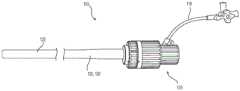
图1是示例性引导器护套的侧视图;Figure 1 is a side view of an exemplary introducer sheath;
图2是用于植入假体瓣膜的示例性血管内递送设备的侧视图;Figure 2 is a side view of an exemplary intravascular delivery device for implanting a prosthetic valve;
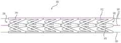
图3是示例性支撑结构的侧视图;Figure 3 is a side view of an exemplary support structure;
图4是图3的支撑结构的立体图;Fig. 4 is a perspective view of the support structure of Fig. 3;
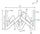
图5是处于非扩张构型的可扩张环的前视图;Figure 5 is a front view of the expandable ring in a non-expanded configuration;
图6是处于扩张构型的图5的可扩张环的前视图;Figure 6 is a front view of the expandable ring of Figure 5 in an expanded configuration;
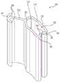
图7是图5的可扩张环的立体图;Figure 7 is a perspective view of the expandable ring of Figure 5;
图8是图5的可扩张环的俯视图;Figure 8 is a top view of the expandable ring of Figure 5;
图9是图5的可扩张环的平展图;Figure 9 is a flattened view of the expandable ring of Figure 5;
图10是示例性可扩张环的前视图;Figure 10 is a front view of an exemplary expandable ring;
图11是图10的可扩张环的立体图;Figure 11 is a perspective view of the expandable ring of Figure 10;
图12是示例性可扩张环的前视图;Figure 12 is a front view of an exemplary expandable ring;
图13是图12的可扩张环的立体图;Figure 13 is a perspective view of the expandable ring of Figure 12;
图14是示例性可扩张环的前视图;Figure 14 is a front view of an exemplary expandable ring;
图15是图14的可扩张环的立体图;Figure 15 is a perspective view of the expandable ring of Figure 14;
图16是处于非扩张构型的示例性可扩张支撑结构的俯视立体图;16 is a top perspective view of an exemplary expandable support structure in a non-expanded configuration;
图17是处于扩张构型的图16的支撑结构的俯视立体图;17 is a top perspective view of the support structure of FIG. 16 in an expanded configuration;
图18是图16的支撑结构的元件的俯视立体图;18 is a top perspective view of elements of the support structure of FIG. 16;
图19是图18的元件的俯视图;Figure 19 is a top view of the element of Figure 18;
图20是用于可扩张支撑结构的示例性元件的俯视图;和Figure 20 is a top view of an exemplary element for an expandable support structure; and
图21是用于可扩张支撑结构的示例性元件的俯视图。21 is a top view of an exemplary element for an expandable support structure.
各个附图中相同的参考符号指示相同的元件。The same reference symbols in the various drawings indicate the same elements.
具体实施方式Detailed ways
对本发明构思的某些实例的以下描述不应当用于限制权利要求的范围。通过下面的描述,其它实例、特征、方面、实施方式、和优点对于本领域技术人员将变得明显。如将认识到的,装置和/或方法能够具有其它不同和明显的方面,所有这些都不脱离本发明构思的精神。因此,附图和描述应被认为本质上是说明性的而不是限制性的。The following description of certain examples of the inventive concept should not be used to limit the scope of the claims. Other examples, features, aspects, implementations, and advantages will become apparent to those skilled in the art from the following description. As will be realized, the apparatus and/or method are capable of other different and obvious aspects, all without departing from the spirit of the inventive concept. Accordingly, the drawings and descriptions should be regarded as illustrative in nature and not restrictive.
为了此描述的目的,本文描述了本公开的实施方式的某些方面、优点和新颖特征。所描述的方法、系统、和设备不应被解释为以任何方式进行限制。相反,本公开单独地和以彼此各种组合和子组合的方式涉及各种公开的实施方式的所有新颖的和非显而易见的特征和方面。所公开的方法、系统、和设备不限于任何具体方面、特征、或其组合,所公开的方法、系统、和设备也不要求存在任何一个或多个具体优点或要求任何一个或多个具体问题得以解决。For the purposes of this description, certain aspects, advantages and novel features of embodiments of the disclosure are described herein. The described methods, systems, and devices should not be construed as limiting in any way. Rather, the present disclosure relates to all novel and non-obvious features and aspects of the various disclosed embodiments both individually and in various combinations and subcombinations with one another. The disclosed methods, systems, and devices are not limited to any specific aspect, feature, or combination thereof, nor do the disclosed methods, systems, and devices claim any one or more specific advantages or require any one or more specific problems be resolved.
除非与其相不相容,否则结合本发明的特定方面、实施方式或实例描述的特征、整数、特性、化合物、化学部分、或基团应理解为适用于本文描述的任何其它方面、实施方式或实例。除了这样的组合之外,该组合中这样的特征和/或步骤中的至少一些是互斥的,在此说明书(包括任何所附权利要求、摘要和附图)中公开的所有特征,和/或如此公开的任意方法或过程的所有步骤都可以以任意组合进行组合。本发明不限于任何前述实施方式的细节。本发明扩展至此说明书(包括任何所附权利要求、摘要和附图)中公开的特征的任意新颖的一个、或任意新颖的组合,或者扩展至如此公开的任意方法或过程的步骤的任意新颖的一个、或任意新颖的组合。Features, integers, characteristics, compounds, chemical moieties, or groups described in conjunction with a particular aspect, embodiment, or example of the invention are to be understood to be applicable to any other aspect, embodiment, or example described herein unless incompatible therewith. instance. Except for combinations in which at least some of such features and/or steps are mutually exclusive, all features disclosed in this specification (including any accompanying claims, abstract and drawings), and/ Or all steps of any method or process so disclosed may be combined in any combination. The invention is not restricted to the details of any foregoing embodiments. The invention extends to any novel one, or any novel combination, of the features disclosed in this specification (including any accompanying claims, abstract and drawings), or to any novel step of any method or process so disclosed One, or any novel combination.
应当理解,被说成通过引用以全部或部分并入本文的任何专利、出版物、或其它公开材料,仅在所并入的材料不与此公开中阐述的现有定义、陈述、或其它公开材料冲突的程度上并入本文。因此,在必要的程度上,本文明确阐述的公开内容取代通过引用并入本文的任何冲突材料。被说成通过引用并入本文但与本文阐述的现有定义、陈述、或其它公开材料相冲突的任何材料或其部分,仅在所并入的材料和现有公开材料之间没有出现冲突的程度上并入。It should be understood that any patent, publication, or other disclosure material that is said to be incorporated by reference herein, in whole or in part, only to the extent that the incorporated material does not contradict a prior definition, statement, or other disclosure set forth in the disclosure. The extent to which the materials conflict is incorporated herein. Accordingly, to the extent necessary, the disclosure as expressly set forth herein supersedes any conflicting material incorporated herein by reference. Any material, or portion thereof, that is said to be incorporated by reference herein conflicts with existing definitions, statements, or other disclosed material set forth herein, only to the extent that no conflict arises between the incorporated material and the existing disclosed material incorporated to a certain extent.
如说明书和所附权利要求中使用的,除非上下文另外明确指示,否则单数形式的“一”、“一个”和“所述”包括复数指代。范围在本文中可以表示为从“约”一个特定值,和/或到“约”另一特定值。当表示这样的范围时,另一方面包括从这个特定值,和/或到另一特定值。类似地,当通过使用先行词“约”将值表示为近似值时,将理解的是,特定值形成另一方面。还将进一步理解的是,范围中的每一个的端点无论是与另一个端点相关还是独立于另一个端点,都是有意义的。As used in the specification and the appended claims, the singular forms "a", "an" and "the" include plural referents unless the context clearly dictates otherwise. Ranges can be expressed herein as from "about" one particular value, and/or to "about" another particular value. When such a range is expressed, on the other hand, from the particular value, and/or to another particular value is included. Similarly, when values are expressed as approximations, by use of the antecedent "about," it will be understood that the particular value forms another aspect. It will also be further understood that the endpoints of each of the ranges are meaningful whether in relation to the other endpoints or independently of the other endpoints.
“任选的”或“任选地”意指随后描述的事件或情况可能发生或可能不会发生,以及意指该描述包括在所述事件或情况发生时的实例和在其不发生时的实例。"Optional" or "optionally" means that the subsequently described event or circumstance may or may not occur, and that the description includes instances when said event or circumstance occurs and instances when it does not. instance.
贯穿此说明书的描述和权利要求,词语“包含(comprise)”及该词语的变体,如“包含(comprising)”和“包含(comprises)”,意指“包括但不限于”,并且不意图排除例如其它添加物、部件、整数或步骤。“示例性的”意指“……的实例”,并且不意图传达对优选或理想方面的指示。“诸如”并非以限制性含义使用,而是用于解释的目的。Throughout the description and claims of this specification, the word "comprise," and variations of that word, such as "comprising" and "comprises," means "including but not limited to," and is not intended to For example other additives, components, integers or steps are excluded. "Exemplary" means "an example of" and is not intended to convey an indication of a preferred or ideal aspect. "Such as" is not used in a limiting sense, but for purposes of explanation.
本文使用的术语“近侧的”和“远侧的”是指护套、导管、或递送组合件的区域。“近侧的”意指最靠近装置的手柄的区域,而“远侧的”意指最远离装置的手柄的区域。如本文所用,“轴向地”或“轴向的”是指沿着护套的纵向轴线的方向。As used herein, the terms "proximal" and "distal" refer to regions of the sheath, catheter, or delivery assembly. "Proximal" means the area closest to the handle of the device, and "distal" means the area furthest from the handle of the device. As used herein, "axially" or "axial" refers to a direction along the longitudinal axis of the sheath.
如本文所使用的术语“管”或“管状的”并不意指将形状限制为圆形横截面。代替地,管或管状的可以指代具有封闭横截面和轴向延伸通过其中的腔的任何伸长的结构。管还可以具有一些选择性位于其中的狭缝或开口——但它仍将提供足够的封闭结构以将其它部件容纳在其腔(一个或多个)内。The term "tube" or "tubular" as used herein is not meant to limit the shape to a circular cross-section. Alternatively, tube or tubular may refer to any elongated structure having a closed cross-section and a lumen extending axially therethrough. The tube may also have some slits or openings optionally located therein - but it will still provide a sufficient closure to accommodate other components within its lumen(s).
本文公开的可扩张引导器护套用于通过患者的脉管系统将假体装置递送至身体内的程序部位。如将在下面进一步详细描述的,护套被构造成在周向方向上高度可扩张和可皱缩,同时还使护套的壁厚最小,以使递送系统的轮廓在递送期间最小。在一个实例中,可扩张护套包括沿着护套的纵向轴线对准的多个径向可扩张环。可扩张环提供管状支撑结构,该管状支撑结构促进护套的径向扩张,同时维持护套的总长度。在另一个实例中,护套包括多个伸长的径向构件,该径向构件被周向地布置以限定管状支撑结构。伸长的径向构件中的每一个可滑动地与相邻构件互相连接,以促进护套的最大径向扩张,同时维持护套长度。The expandable introducer sheath disclosed herein is used to deliver a prosthetic device through a patient's vasculature to a procedural site within the body. As will be described in further detail below, the sheath is configured to be highly expandable and collapsible in the circumferential direction while also minimizing the wall thickness of the sheath to minimize the profile of the delivery system during delivery. In one example, the expandable sheath includes a plurality of radially expandable rings aligned along the longitudinal axis of the sheath. The expandable ring provides a tubular support structure that facilitates radial expansion of the sheath while maintaining the overall length of the sheath. In another example, the sheath includes a plurality of elongated radial members circumferentially arranged to define a tubular support structure. Each of the elongate radial members is slidably interconnected with adjacent members to facilitate maximum radial expansion of the sheath while maintaining sheath length.
图1示例了根据本公开的引导器护套系统100。如将在下文描述的,引导器护套系统100被配置成与递送设备200(图2)一起使用,用于将诸如假体心脏瓣膜的假体植入物递送给患者。例如,在使用时,图2中所示的代表性递送设备200的引导导管214的轴222被插入通过图1中所示的引导器护套系统100的手柄105和护套120,以向患者递送假体装置。FIG. 1 illustrates an
如图1中示例的,引导器护套系统100的护套120包括外部管状构件150和内部管状构件130(在图1中不可见),其中外部管状构件150提供在内部管状构件130上延伸的弹性层。例如,外部构件150可以由诸如硅酮或聚氨酯的弹性体材料形成。弹性体外部管状构件150将拉伸,以顺应(共形于,conform to)下面的结构的扩张状态。引导器护套系统100包括提供在护套120的近端处的手柄105。在使用时,递送设备200被插入通过延伸通过手柄105和护套120两者的中心腔,以用于递送假体植入物。止血阀被包括在中心腔的近端处,防止加压血液从引导器护套系统100渗漏出去。As illustrated in FIG. 1 , the
图2示例了代表性的递送设备200。本文所述的递送设备200仅是示例性的,其它类似的递送系统可与引导器护套系统100一起使用。图2中示例的递送设备200包括可操纵的引导导管214,引导导管214包括耦接到伸长的轴222的手柄部分220。球囊导管216延伸通过引导导管214的手柄部分220和伸长的轴222,并且与球囊240流体连通。图2中示例的引导导管214和球囊导管216适于相对于彼此纵向滑动,以促进假体心脏瓣膜递送并定位在患者身体内的植入部位处。在图2中,描绘了处于膨胀状态的球囊240,但是应当理解,球囊240在推进通过引导器护套系统100和患者的脉管系统期间是瘪缩的。假体心脏瓣膜或其它假体装置可被折绉(crimped)在球囊240上,以用于递送至程序部位。递送设备200还包括冲洗管材224,以防止气泡进入血流。FIG. 2 illustrates a representative delivery device 200 . The delivery device 200 described herein is exemplary only, and other similar delivery systems may be used with the
通常,在插入之前,护套120与引导器耦接,该引导器被插入通过中心腔并用于使护套变硬以防止在插入到患者体内期间皱缩。护套120的远端穿过患者的皮肤并进入到血管(如股动脉)中。然后,引导导管214的轴222通过近侧止血阀插入到引导器护套系统100中。递送设备200的轴222被推进通过患者的脉管系统,以将假体装置递送给患者。冲洗管材118被附接到引导器护套系统100,并用于在将护套120推进到患者体内之前用盐水或另一种生理平衡溶液来填充系统,以确保没有气泡引导到血流中。Typically, prior to insertion, the
图3至图21示例了包括在引导器护套120中的用于与诸如图2中所示的递送设备200一起使用的各种示例性支撑结构300。护套120适于允许护套120的一部分的临时(局部)径向扩张,以适应递送设备200通过护套120的中心腔并进入到患者的血管中以递送、移除、修复、和/或置换假体装置。这种引导器护套120还可用于其它类型的微创手术,诸如需要将设备引导到对象的血管中的任何手术。例如,护套120还可以用于引导其它类型的递送设备,以用于将各种类型的管腔内装置(例如,支架、带支架的移植物等)放置到多种类型的脉管体腔和非脉管体腔(例如,静脉、动脉、食道、胆管树(biliary tree)的道、肠道、尿道、输卵管、其它内分泌或外分泌道等)中。3-21 illustrate various
护套120可包括各种支撑结构300,以在推进通过患者和递送设备200的通过期间径向和轴向地支撑护套120,并防止护套120在推进到患者体内期间弯曲或扭结。支撑结构300还促进护套120的一部分的临时(局部)径向扩张,以适应递送设备200的通过和假体装置的递送。支撑结构300可耦接至内部管状构件130的内表面或外表面,或者封装在内部管状构件130内。考虑了用于将支撑结构300耦接到内部管状构件130的任意形式的机械或化学紧固件。例如,可以使用粘合剂将支撑结构300化学粘结到内部管状构件130的内表面。在另一实例中,可以使用缝线、线状物、丝线、铆钉、螺钉、销、或类似元件将支撑结构300机械地耦接至内部管状构件130。尽管支撑结构300在本文中描述为耦接至内部管状构件130,但是考虑了可以使用类似的耦接/紧固机构将支撑结构300耦接至内部管状构件130和外部管状构件150中的一个(或两者)。The
支撑结构300可以由刚度大于内部管状构件130和外部管状构件150的刚度的材料构造。例如,支撑结构300可以由任何生物相容性材料构造,包括但不限于复合材料、聚合物、增强聚合物、以及诸如不锈钢、钛、钛合金、钴铬合金、镍钛诺等的金属。因此,支撑结构300增加护套120的推/拉力,同时还防止在递送设备200和假体装置推进时的扭结。支撑结构300与可扩张内部管状构件130的组合提供了这样的护套120:具有高推/拉力,与此同时又是柔软且挠性的,并且能够径向地扩张。
图3和图4示例了包括多个径向可扩张环310的示例性支撑结构300。相邻的环310耦接在一起并且沿着内部管状构件130/护套120的纵向轴线轴向地对准。所产生的管状结构在周向方向上具有大致均匀的厚度,并且其长度由耦接的环310的组合高度限定。支撑结构300限定中心腔330,以允许递送设备200的通过和假体装置通过支撑结构300/内部管状构件130的递送。如将在下文描述的,可扩张环310在非扩张状态和扩张状态之间径向地扩张,以促进内部管状构件130/护套120的径向扩张,同时维持护套120和支撑结构300的总长度。3 and 4 illustrate an
虽然图3和图4中示例的支撑结构300的部分仅包括六个可扩张环310,但是考虑了支撑结构300可以包括多于六个的径向可扩张环310。径向可扩张环310中的每一个可具有约1.0mm至10.0mm的高度(H)。在另一实例中,径向可扩张环310中的每一个可具有约5.0mm至约20mm的高度(H)。在又一实例中,径向可扩张环310中的每一个可具有约2.0mm至约20mm的高度(H)。因此,沿着内部管状构件130的整个长度耦接的示例性支撑结构300将具有多于25个的径向可扩张环310。支撑结构300中包括的可径向扩张的环310的数量可以根据所执行的程序、患者的解剖结构、所期望的支撑结构300的挠性、和/或所期望的支撑结构300的扩张速率来调节。例如,支撑结构300可耦接至内部管状构件130的长度的一部分,其中所使用的径向可扩张环310的数量对应于所期望的支撑结构300的长度。While the portion of
径向可扩张环310沿着内部管状构件130/护套120的纵向轴线轴向地对准。环310沿着穿过多个可扩张环310中的每一个的耦接构件320耦接在一起。耦接构件320可包括丝线、编织缆线、和/或聚合物缝线。示例性耦接构件320包括聚合物丝线或金属丝线、复合材料编织缆线、或由Dyneema构造的聚合物缝线。在耦接构件320上提供足够的张力,以维持可扩张环310沿着支撑结构300和内部管状构件130的轴向/纵向位置。另外,在耦接构件320上提供足够的张力,以维持可扩张环310处于紧邻/毗邻的构型中,从而使相邻可扩张环310之间的任何轴向移动或间隙最小。The radially
如图3和图4中提供的,径向可扩张环310在耦接时形成伸长的管状支撑结构300。当递送设备200穿过支撑结构300(和内部管状构件130)的中心腔330时,径向可扩张环310中的每一个将独立地沿径向方向从非扩张状态扩张到扩张状态。例如,当递送设备200穿过支撑结构300的中心腔330时,假体装置和递送设备200在相邻的径向可扩张环310上施加径向向外定向的力。径向可扩张环310在内部管状构件130和弹性外部管状构件150上施加相应的径向向外定向的力,从而导致内部管状构件130和外部管状构件150两者都局部地扩张以适应假体装置/递送设备200的轮廓。一旦假体装置/递送设备200穿过,可扩张环310就独立地恢复至非扩张直径。即,可扩张环310以及内部管状构件130和外部管状构件150返回到它们的原始的非扩张构型。在一些实施方式中,这是通过具有比内部管状构件130更高的弹性模量的外部管状构件150来促进的。在此构型中,外部管状构件150促使(urges)内部管状构件130回到其非扩张构型。如果需要,可以在中心腔330内提供润滑衬垫,以减少穿过的递送设备200/假体装置与支撑结构300之间的摩擦。合适的润滑衬垫的实例可以由诸如PTFE、聚乙烯、聚偏氟乙烯、及其组合的材料构造。As provided in FIGS. 3 and 4 , the radially
图5提供了处于非扩张状态的单个径向可扩张环310的侧视图。可扩张环310包括围绕可扩张环310周向地间隔的若干纵向延伸的梁312。梁312在平行于可扩张环310的纵向轴线314和内部管状构件130的方向上延伸。支柱316在梁312中的每一个之间延伸并连接梁312中的每一个。如图5(和图9)中示例的,支柱316限定大致“V”形形状。支柱316包括从相邻的梁312a和312b以锐角(α)延伸的第一腿322和第二腿324。第一腿322和第二腿324在顶端326处会合(meet),使得在腿322、324之间限定锐角(β)。考虑了支柱316的其它形状和样式。例如,支柱316还可限定大致“U”形形状、大致“W”形形状、或连接相邻的梁312的任意其它规则或不规则的形状,以促进可扩张环310的径向扩张。如图5中示例的,支柱316的顶端326具有(非扩张的)高度,该高度对应于梁312的高度(H)。尽管未示例,但是考虑了顶端326可以具有小于或大于梁312的高度(H)的(非扩张的)高度。在一个实施方式中,支柱316的顶端326朝着支撑结构300/内部管状构件130的远端定向。在另一实施方式中,支柱316的顶端326朝着支撑结构300/内部管状构件130的近端定向。在又一实施方式中,相邻的可扩张环310的顶端326相对于支撑结构300/内部管状构件130的近端或远端交替定向。Figure 5 provides a side view of a single radially
图6提供了处于扩张状态的图5的可扩张环310的侧视图。如图5和图6中示例的,可扩张环310的直径在非扩张直径(D1)和扩张直径(D2)之间增加。在扩张期间,支柱316在非扩张状态与扩张状态之间周向地扩张,使得相邻的梁312之间的周向距离(弧长)随着可扩张环310直径的增加而增加。在一些实施方式中,当可扩张环310在扩张状态与非扩张状态之间移动时,支柱316弹性地变形。例如,支柱316在穿过的假体装置/递送设备200的力的作用下暂时改变形状,并且一旦该装置/设备穿过,就返回到它们的原始形状。如图6中示例的,支柱316显示已经围绕扩张的环310的周长周向地挠曲、移动、和/或伸长,使得腿322、324与相邻的梁312a、312b之间的角度(α)增加,腿322、324之间的角度(β)增加,并且支柱316的顶端326的高度(H2)减小。一旦假体装置/递送设备200穿过可扩张环310,支柱316就将返回其原始的非扩张构型。FIG. 6 provides a side view of the
如图5和图6中示例的,虽然梁312之间的周向距离增加,但是在扩张期间可扩张环310和梁312的高度(H)不变。因为纵向梁312在扩张期间不挠曲或弯曲,所以梁312的高度(H)保持恒定,并且支撑结构300和内部管状构件130的总长度保持恒定。As illustrated in Figures 5 and 6, while the circumferential distance between
如上概述,支撑结构300的可扩张环310可以由任意生物相容性材料构造,包括复合材料、聚合物(如PEEK(聚醚醚酮)、POM(聚甲醛,如杜邦的DELRIN))、或其它增强聚合物(如PARA(聚丙烯酰胺,如Solvay的IXEF)、和金属(例如,不锈钢、钛、钛合金、钴铬合金、镍钛诺)、以及其它能够弹性变形的类似材料。尽管支柱316总体上被描述为由可弹性变形的材料构造,但是支柱316和/或梁312也可以由能够塑性变形的材料构造。在这些实施方式中,支撑结构300将在扩张时维持其扩张形状。As outlined above, the
虽然示例性支撑结构300中包括的可扩张环310中的每一个都可以由相同的材料构造,但是考虑了支撑结构300内的各种环310可以由不同的材料构造。例如,多个可扩张环310中的至少一个可以由刚度大于或小于其余可扩张环310的刚度的材料构造。考虑到由较硬材料构造的环310提供更大的抗扩张性,并且由较挠性材料构造的环310通常将更具挠曲性(并且挠曲得更快),通过提供变化的刚度/挠性的可扩张环310,可以控制支撑结构300的各个部分的扩张速率和扩张量。还考虑了可扩张环310的不同部件可以由不同的材料构造。例如,在给定的可扩张环310内,梁312可以由与支柱316不同的材料构造。在一个实例中,支柱316可以由具有高弹性挠性的材料构造,以促进在扩张构型和非扩张构型之间的径向移动,而梁312可以由更硬的材料构造,从而增加支撑件结构300/护套120的推/拉强度。还考虑了可以沿着相同的支撑结构300提供具有不同高度(H)的可扩张环310。同样地,可以沿着相同的支撑结构300提供具有不同的支柱316形状(V形、U形等)的可扩张环310。通过改变材料(在环310之间和在环310部件之间两者)、高度、和/或支柱形状,可以构造具有特定物理特性的支撑结构300。例如,可以构造具有特定的高推力,同时还维持对柔软性、挠性、和径向扩张的具体要求的支撑结构300。While each of the expandable rings 310 included in the
图7和图8提供了可扩张环310的俯视图。如上所述,耦接构件320延伸穿过可扩张环310中的每一个,并且沿支撑结构300纵向地耦接单独的环310。在组装期间,环310被轴向地对准,使得相邻的环的对应通孔332、334对准。耦接构件320延伸穿过通孔332、334,并沿着支撑结构300固定可扩张环310的轴向/纵向位置和旋转位置。7 and 8 provide top views of
如图7和图8中提供的,梁312和/或支柱316可以包括通孔332、334,用于接收耦接构件320。在梁312上,通孔332从顶表面336纵向地并沿直线延伸通过梁312的底表面338。同样,在支柱316上,通孔334从支柱316的顶端326纵向地并沿直线延伸通过支柱316的厚度,到达在两个腿322、324之间限定的内部弯曲部328。尽管图7和图8示例了提供在纵向梁312中的每一个和支柱316中的每一个上的通孔332、334,但是不需要每一个梁312和支柱316都包括经由单独的耦接构件320连接的通孔332、334。在一些实施方式中,仅一个耦接构件320延伸通过单个梁312或单个支柱316,以耦接包括支撑结构300的一系列可扩张环310。As provided in FIGS. 7 and 8 ,
通孔332、334可具有光滑的表面或带纹理的表面。在一些实施方式中,通孔332、334可包括用于与提供在耦接构件320上的对应螺纹接合的螺纹。通孔332、334可沿着可扩张环310的长度具有恒定或变化的直径。还考虑了沿着支撑结构300的长度的各种环310可以包括具有各种表面光洁度/纹理、螺纹、和/或直径的通孔332、334。通过改变通孔332、334的表面结构和/或尺寸,可以控制环310/通孔332、334与耦接构件320之间的耦接。例如,通过以与通孔332、334的尺寸/形状相对应的尺寸和/或形状来构造耦接构件320,可以阻止或以其它方式限制环310相对于耦接构件320的纵向移动和旋转移动。在实例中,通孔332、334可包括提供在其内表面上的凹槽或凹部,该凹槽或凹部被设定尺寸和形状以对应于从耦接构件320延伸的突出部,使得防止或限制环310在耦接构件320上旋转。同样,通孔332、334可包括螺纹部分或直径减小的部分,该螺纹部分或直径减小的部分干涉/接触耦接构件320的对应部分,以沿着/围绕耦接构件320固定环310的纵向位置和旋转位置。The
纵向梁312和/或支柱316还可以包括被设定尺寸并被配置以与提供在相邻的环310上的对应部件耦接的配合部件(未示出)。例如,梁312的顶表面336可包括被设定尺寸并被定位以与提供在相邻的梁312的底表面338上的对应凹部接合的突出部。配合部件可被包括在环310的单个梁312上或所有的梁312上。在示例性实施方式中,包括在支撑结构300上的环310中的每一个的一个梁312包括配合部件。在另一实例中,如上所述,所有的梁312都包括配合部件,并且耦接构件320延伸通过支柱316。
进一步示例了支柱316和梁312之间的关系,图9示例了沿着纵向梁312切割并平放的非扩张的可扩张环310。可扩张环310可通过创建图9中示例的形式并将环310的相对侧联结在一起来制造。例如,图9中提供的结构可以通过注射成型或激光切割一片材料来形成,并且沿着梁312将环310的相对端焊接或以其它方式固定地联结在一起。环310还可以通过从圆柱形材料片或管状材料片激光切割或机械地切割梁312和支柱316来制造。Further illustrating the relationship between
图10和图11提供了具有替代的支柱316构型的示例性可扩张环310的侧视图和立体图。图10和图11的可扩张环310具有相似的部件、操作,并且通过与图3至图9的可扩张环310相似的方法制造。因此,下面将仅描述图10和图11的可扩张环310之间的差异。相同的参考编号用于指示相同的元件。10 and 11 provide side and perspective views of an exemplary
图10和图11中描绘的可扩张环310可以与另外的可扩张环310(具有相似的设计或变化的设计)串联耦接,并且沿着内部管状构件130/护套120的纵向轴线轴向地对准,以形成伸长的管状支撑结构300。如图10和图11中示例的,可扩张环310包括在相邻的梁312a、312b之间延伸的上支柱316a和下支柱316b。上支柱316a和下支柱316b各自限定大致“V”形形状,并且组合起来限定大致菱形形状。上支柱316a包括第一腿322a和第二腿324a,第一腿322a和第二腿324a从相邻的梁312a和312b的中点朝向环310/梁312的顶表面336以锐角(α)延伸。第一腿322a和第二腿324a在顶端326a处会合,使得在腿322a、324a之间限定了锐角(β)。下支柱316b包括第一腿322b和第二腿324b,第一腿322b和第二腿324b从相邻的梁312a和312b的中点朝向环310/梁312的底表面338以锐角(α)延伸。第一腿322b和第二腿324b在顶端326b处会合,使得在腿322b、324b之间限定了锐角(β)。如图10中示例的,上支柱316a和下支柱316b的顶端326a、326b各自具有的高度对应于非扩张的环310的高度(H)。与图5和图6中描绘的可扩张环310相似,当图10和图11的环310扩张时,上支柱316a和下支柱316b将围绕扩张的环310的周长周向地挠曲、移动、和/或伸长,使得角度(α)和角度(β)增加,而上支柱316a和下支柱316b的顶端326a、326b的高度将减小。一旦假体装置/递送设备200穿过可扩张环310,则上支柱316a和下支柱316b将返回到它们的原始的非扩张构型。The
图12和图13提供了具有替代的支柱316构型的示例性可扩张环310的侧视图和立体图。图12和图13的可扩张环310具有相似的部件、操作,并且通过与图3至图11的可扩张环310相似的方法制造。因此,下面将仅描述图12和图13的可扩张环310之间的差异。相同的参考编号用于指示相同的元件。12 and 13 provide side and perspective views of an exemplary
图12和图13中描绘的可扩张环310可以与另外的可扩张环310(具有相似的设计或变化的设计)串联耦接,并且沿着内部管状构件130/护套120的纵向轴线轴向地对准,以形成伸长的管状支撑结构300。如图12和图13中示例的,可扩张环310包括在相邻的梁312a、312b之间延伸的上支柱316a和下支柱316b。上支柱316a和下支柱316b各自限定弯曲的“V”形。上支柱316a包括具有凹形弯曲形状的第一腿322a和第二腿324a,第一腿322a和第二腿324a从相邻的梁312a和312b的中点朝向环310/梁312的顶表面336延伸。类似地,下支柱316b包括具有凹形形状的第一腿322b和第二腿324b,第一腿322b和第二腿324b从相邻的梁312a和312b的中点朝向环310/梁312的底表面338延伸。如图11中示例的,上支柱316a和下支柱316b的顶端326a、326b各自具有的高度对应于非扩张的环310的高度(H)。与图5和图6中描绘的可扩张环310相似,当图12和图13的环310扩张时,上支柱316a和下支柱316b将围绕扩张环310的周长周向地挠曲、移动、和/或伸长,使得上支柱316a的第一腿322a和第二腿324a的曲率,以及下支柱316b的第一腿322b和第二腿324b的曲率将减小,而上支柱316a和下支柱316b的顶端326a、326b的高度将减小。一旦假体装置/递送设备200穿过可扩张环310,则上支柱316a和下支柱316b将返回到它们的原始的非扩张构型。The
图14和图15提供了示例性支撑结构300的侧视图和立体图。支撑结构300包括耦接在一起并沿着内部管状构件130/护套120的纵向轴线轴向地对准以形成伸长的管状结构的若干径向可扩张环310。图14和图15的可扩张环310具有相似的部件、操作,并且通过与图3至图13的可扩张环310相似的方法制造。因此,下面将仅描述图14的可扩张环310之间的差异。相同的参考编号用于指示相同的元件。如图14和图15中示例的,可扩张环310中的每一个包括围绕可扩张环310的圆周间隔的若干环形支柱316。支柱316可限定具有大致平坦且平行的外表面和内表面的环面形状或圆形/环形形状。相邻的支柱316在环形支柱316的周长上的位置处耦接。如图14和图15中提供的,环形支柱316可以在支柱316的周长上的相对点处耦接。例如,第一耦接点342可以位于支柱316的周长上的第一位置,而第二耦接点344可以位于围绕支柱316的周长180度的位置。至少一个耦接构件320被用于联结相邻的环310并用来维持可扩张环310沿着支撑结构300和内部管状构件130的轴向/纵向位置。环形支柱316包括用于接收耦接构件320的通孔340。通孔340在与环310的顶表面336相邻的边缘处延伸通过环形支柱316,并通过与环310的底表面338相邻的边缘。在支撑结构300的扩张期间,单独的环形支柱316随着可扩张环310的直径增加而变形/挠曲。如上概述的,在非扩张状态下,环形支柱316具有大致圆形的形状。在扩张状态下,随着可扩张环310的直径/周长增加,环形支柱316改变形状。例如,当可扩张环310扩张时,环形支柱316弹性变形以具有大致椭圆形或卵形的形状,其中当可扩张环310扩张时,环形支柱316的高度(H)减小。14 and 15 provide side and perspective views of an
在图16至图21中所示的另一实施方式中,支撑结构300包括周向地布置以限定支撑结构300/内部管状构件130/护套120的管状形式的多个互相连接的径向构件350。伸长的径向构件350中的每一个可滑动地连接到相邻的径向构件350,以促进支撑结构300的扩张。相邻的径向构件350之间的可滑动连接适应递送设备200的通过以及假体装置通过支撑结构300的中心腔330的递送。像图3至图15的支撑结构300一样,可以在中心腔330内提供润滑衬垫,以减少穿过的递送设备200/假体装置与支撑结构300之间的摩擦。In another embodiment shown in FIGS. 16-21 , the
图16和图17提供了示例性可扩张支撑结构300的俯视立体图。图16示例了处于非扩张状态的支撑结构300,而图17示例了处于扩张状态的支撑结构。就图3至图15的支撑结构300之间存在相似性的程度而言,相同的参考编号用于指示相同的元件。16 and 17 provide top perspective views of an exemplary
如图16和图17中提供的,支撑结构300包括多个伸长的径向构件350。径向构件350中的每一个形成将沿内部管状构件130的长度延伸的伸长的结构。每一个径向构件350包括锁定臂352和保持部分354。如图15和图16中示例的,径向构件350围绕支撑结构300周向地布置,使得径向构件350中的每一个的锁定臂352可滑动地接合相邻径向构件350的对应的保持部分354。锁定突出部356从锁定臂352的末端延伸。当被耦接时,锁定突出部356和锁定臂352延伸到包括在相邻径向构件350的保持部分354中的通道358中。锁定突出部356和锁定臂352被设定尺寸并被配置以在通道358内自由滑动。As provided in FIGS. 16 and 17 , the
径向构件350周向地移动以使支撑结构300在非扩张状态和扩张状态之间径向地扩张,从而促进内部管状构件130/护套120的径向扩张,同时维持支撑结构300的总长度。如图16和图17中示例的,锁定臂352/锁定突出部356在保持部分354的通道358内沿围绕支撑结构300的圆周的方向移动/滑动。当锁定臂352/锁定突出部356从邻近通道358的末端360的第一位置朝向提供在保持部分354中的开口362移动时,支撑结构300的周长/直径增加。如图16和图17中提供的,支撑结构300的直径(D2)(和周长)大于支撑结构300的非扩张直径(D1)(和周长)。还考虑了锁定臂352可以在相邻的径向构件350的通道358内轴向地滑动。例如,在组装期间,径向构件350中的每一个可以被单独地构造,并且可以通过使第一径向构件350的锁定臂352滑入到相邻的径向构件350的通道358/保持部分345中,直到构造支撑结构300的管状形式来组装。如将在下面更详细地讨论的,也可以迫使锁定臂352通过开口362并进入到相邻的径向构件350的保持部分354中。The
尽管图16和图17示例了包括十个径向构件350的支撑结构300,但是考虑了取决于支撑结构300的期望的尺寸、挠性、和扩张特性,可以包括另外的或更少的径向构件350。伸长的径向构件350的长度可以对应于内部管状构件130的长度,使得支撑结构300延伸内部管状构件130的整个长度。在另一实施方式中,伸长的径向构件350沿着内部管状构件130的整个长度的大部分延伸,并且可以沿着内部管状构件130的长度的任意部分定位/耦接至内部管状构件130的长度的任意部分。在另一实施方式中,伸长的径向构件350沿着内部管状构件130的整个长度的小部分延伸,并且可以沿着内部管状构件130的长度的任意部分定位/耦接至内部管状构件130的长度的任意部分。在另一实施方式中,内部管状构件130可包括沿内部管状构件130的纵向轴线轴向地对准的若干支撑结构300(包括可滑动地互相连接的径向构件350)。支撑结构300可以沿着内部管状构件130间隔开或被定位成紧邻/毗邻。支撑结构300可以经由延伸通过支撑结构300中的每一个的耦接构件320来耦接。相邻的支撑结构300可以具有沿着内部管状构件130的长度的变化的长度和间距。例如,第一支撑结构300可以具有长度,例如约10.0mm的长度。沿着内部管状构件130提供的第二支撑件300可以比第一支撑结构300短,例如5.0mm。沿着内部管状构件130提供的第三支撑结构可以比第二支撑结构300短,例如2.5mm。通过提供具有沿着内部管状构件130的变化的长度(和间距)的一系列支撑结构300,可以提高和控制内部管状构件130/护套120的挠性。Although FIGS. 16 and 17 illustrate a
在又一实施方式中,内部管状构件130可包括支撑结构300(包括可滑动地互相连接的径向构件350)和沿着内部管状构件130的纵向轴线轴向地对准的可扩张环310的组合。相邻的支撑结构300和可扩张环310可以沿着内部管状构件130间隔开或者被定位成紧邻/毗邻。相邻的支撑结构300和可扩张环310可以经由延伸通过支撑结构300和可扩张环310中的每一个的耦接构件320来耦接。In yet another embodiment, the inner tubular member 130 may comprise a support structure 300 (comprising
图18示例了单个径向构件350。径向构件350限定横截面为弓形的形状,该形状具有与扩张的和非扩张的支撑结构300和/或内部管状构件130的曲率/半径相对应的曲率。伸长的保持部分354包括弯曲的内壁372和相应塑形的弯曲的外壁374。支撑结构300的壁厚由弯曲的内壁372和弯曲的外壁374之间的保持部分354的厚度限定。在示例性支撑结构300中,壁厚度约0.65mm(2F)。内壁372和外壁374间隔开,使得中空通道358提供在它们之间。通道358具有足以允许锁定臂352和相邻径向构件350的锁定突出部356自由周向移动的开口。通道358的末端360提供了接触表面,用于限制锁定突出部356/锁定臂352的移动。在一个实例中,通道358的末端360可具有对应于锁定突出部356的尺寸和形状的尺寸和形状。在另一实例(未示出)中,通道358的末端360可具有这样的接合部件:该接合部件用于接合锁定突出部356以可释放地接合通道358内的锁定突出部356,并将支撑结构300维持在非扩张构型中。与末端360相对的是通向通道358/保持部分354的进入开口362。进入开口362被设定尺寸并被配置以可滑动地接收相邻径向构件350的锁定臂352。保持部分354可包括在开口362处的接合构件364,用于将锁定突出部356保持在通道358内。如图18中示例的,接合构件364包括向内弯曲的突出表面,该表面从保持部分354的在开口362处的端面366朝向通道358延伸并进入通道358中。提供接合构件364,使得在不使锁定臂352或保持部分354致命变形和/或损坏的情况下,相邻径向构件350的锁定突出部356不能从保持部分354移除。FIG. 18 illustrates a single
如图18和图19中提供的,锁定臂352从保持部分354,沿与开口362相对的周向方向延伸。锁定突出部356从锁定臂352的末端延伸,并且被设定尺寸并被配置以在相邻的径向构件350的通道358内周向地滑动。图18中示例的锁定突出部356限定了横截面是大致U形形状。如将在下面参考图19至图21描述的,考虑了不同形状的锁定突出部356和接合构件364。例如,锁定突出部356可以具有U形、V形、T形、W形、或将锁定突出部356维持在保持部分354的通道358内的任意其它规则或不规则的形状。如图18中示例的,锁定突出部356限定横截面为U形,该横截面包括用于接合保持部分354的接合构件364的两个接触表面368。As provided in FIGS. 18 and 19 , the locking
图20和图21示例了锁定突出部356和对应的接合构件364/开口362的钩型结构。如图20中示例的,钩形(或J形)锁定突出部356从锁定臂352的末端延伸。锁定突出部356包括用于接合保持部分354的接合构件364的平坦且成角度的接触表面368。接合构件364包括相应塑形的,平坦且成角度的表面,使得这两者之间的接触将锁定臂352维持在保持部分354内。同样,开口362被设定尺寸以允许锁定臂352单向/向内移动到保持部分354的通道358中。图21还示例了从锁定臂352的末端延伸的钩形(或J形)锁定突出部356。锁定突出部356包括弯曲的接触表面368,用于接合保持部分354的接合构件364。接合构件364包括相应塑形的弯曲部分,该弯曲部分限定碗状/凹入的尺寸,以接收锁定突出部356的接触表面368,使得这两者之间的接合将锁定臂352维持在保持部分354内。同样,开口362被设定尺寸以允许锁定臂352单向/向内移动到保持部分354的通道358中。20 and 21 illustrate the hook-type configuration of the locking
与图3至图15中示例的支撑结构300相似,图16至图21中提供的示例性支撑结构300和径向构件350可以通过注射成型或激光切割一片材料来形成。图16至图21中提供的支撑结构300和径向构件350也可以通过挤出形成。可以通过推动或以其它方式迫使锁定突出部356通过开口362并进入相邻的径向构件350的通道358中来耦接相邻的径向构件350。还考虑了通过使锁定突出部356从支撑结构300的(开口)末端轴向地通过通道358滑动,然后锁定臂352能够滑动地耦接至相邻的径向构件350的保持部分354。还考虑了可以通过共挤出处于耦接构型的至少两个径向构件350来形成相邻的径向构件350。图16至图21的组装的支撑结构300可以覆盖有弹性涂层。组装的支撑结构300还可耦接至内部管状构件130的内表面或外表面,或被封装在内部管状构件130内。可以在内部管状层130上提供弹性外部管状构件150,其中外部管状层150包括弹性模量大于内部管状层130的弹性模量的材料。Similar to the
如上所述,本公开的护套120可以与将诸如经导管心脏瓣膜的假体装置引导到患者的脉管系统中的各种方法一起使用。例如,护套120可用于递送、移除、修复、和/或置换假体装置。通常,在使用期间,使可扩张护套120穿过患者的皮肤(在一些实施方式中,在导丝上),使得护套120的远端区域被插入到血管(如股动脉)中,然后被推进到更宽的血管(如腹主动脉)。心脏瓣膜假体装置(处于折绉状态)可以围绕球囊240放置在递送设备200的远端部分上。然后将递送设备200插入通过可扩张护套120和假体装置,并将假体装置递送至其在患者体内所植入的治疗部位。As noted above, the
球囊240和假体装置被插入通过支撑结构300(和内部管状构件130)的中心腔330。假体装置和递送设备200在支撑结构300的相邻部分(一个或多个)上施加径向向外定向的力。支撑结构300在内部管状构件130上施加相应的径向向外定向的力,内部管状构件130在弹性外部管状构件150上施加相应的径向向外定向的力,导致内部管状构件130和外部管状构件150两者局部扩张以适应假体装置的轮廓。如以上关于图3至图15描述的,当可扩张环310(单独地)扩张时,支柱316周向地扩张,使得相邻的梁312之间的距离增加,从而增加了支撑结构300的中心腔330的直径。支柱316在穿过的假体装置/递送设备200的力的作用下暂时改变形状,并且一旦该装置/设备200穿过,就返回到它们的原始形状。如以上关于图16至图21描述的,互相连接的径向构件350在扩张构型和非扩张构型之间相对于彼此周向地滑动/移动。每一个径向构件350的锁定臂352在提供于相邻径向构件350中的通道358内周向地滑动,以增加支撑结构300的中心腔330的总直径/周长。在两个实施方式中,当假体装置穿过时,支撑结构300返回到非扩张构型。同样,护套120,包括内部管状层130和外部管状层150,返回到它们的原始的非扩张构型。在一些实施方式中,这是通过具有比内部管状构件130更高的弹性模量的外部管状构件150来促进的。在此构型中,外部管状构件150促使内部管状构件130回到其非扩张构型。
在递送设备200的远端和球囊240穿过护套120的远侧开口之后,假体装置250被定位在治疗部位处,并且球囊240被扩张以部署假体装置。然后,假体装置从非扩张球囊240上的原始折绉构型过渡到扩张球囊240上的扩张/部署构型。一旦球囊240被扩张并且假体装置被定位在治疗部位处,就使球囊240瘪缩并通过护套120撤回。After the distal end of delivery device 200 and
如上所述,可以通过提供由具有比内部管状构件130更高的弹性模量的材料构成的外部管状构件150,来控制内部管状构件130和外部管状构件150的扩张和恢复。结果,外部管状构件150促使内部管状构件130回到非扩张构型。与外部管状构件150相比,内部管状构件130还可以包括更润滑的材料和/或涂层。例如,外部管状构件150可以由聚氨酯、硅酮、和/或橡胶制成,或者并入聚氨酯、硅酮、和/或橡胶。外部管状构件150和内部管状构件130可以由以下制成或并入以下:例如,PTFE(例如

除经导管心脏瓣膜外,本文描述的引导器护套系统100可用于其它类型的微创手术,如需要将设备引入到对象的血管中的任何手术。例如,可扩张护套120可用于将其它类型的递送设备引入,以将各种类型的管腔内装置(例如,支架、带支架的移植物、用于血管成形术程序的球囊导管等)放置到多种类型的脉管体腔和非脉管体腔(例如,静脉、动脉、食道、胆管树的道、肠道、尿道、输卵管、其它内分泌或外分泌道等)中。In addition to transcatheter heart valves, the
尽管为了清楚和理解的目的,已经通过示例和实例的方式在某种详细的程度上描述了本公开的前述实施方式,但是对于本领域技术人员明显的是,可以在本公开的精神和范围内进行某些改变和修改。本文中公开的本发明的范围不应由上面描述的特定公开的实施方式限制,而应仅由对所附权利要求的公正阅读来确定。While the foregoing embodiments of the present disclosure have been described in a degree of detail by way of illustration and example for purposes of clarity and understanding, it will be apparent to those skilled in the art that other embodiments that can be implemented within the spirit and scope of the present disclosure can be performed. subject to certain changes and modifications. It is intended that the scope of the present invention disclosed herein should not be limited by the particular disclosed embodiments described above, but should be determined only by a fair reading of the appended claims.
Claims (20)
Translated fromChinesePriority Applications (1)
| Application Number | Priority Date | Filing Date | Title |
|---|---|---|---|
| CN202310272855.9ACN116269937A (en) | 2018-04-30 | 2019-04-24 | Push-on sheath style |
Applications Claiming Priority (3)
| Application Number | Priority Date | Filing Date | Title |
|---|---|---|---|
| US201862664831P | 2018-04-30 | 2018-04-30 | |
| US62/664,831 | 2018-04-30 | ||
| PCT/US2019/028833WO2019212814A1 (en) | 2018-04-30 | 2019-04-24 | Advanced sheath patterns |
Related Child Applications (1)
| Application Number | Title | Priority Date | Filing Date |
|---|---|---|---|
| CN202310272855.9ADivisionCN116269937A (en) | 2018-04-30 | 2019-04-24 | Push-on sheath style |
Publications (2)
| Publication Number | Publication Date |
|---|---|
| CN112236186A CN112236186A (en) | 2021-01-15 |
| CN112236186Btrue CN112236186B (en) | 2023-04-04 |
Family
ID=66821307
Family Applications (2)
| Application Number | Title | Priority Date | Filing Date |
|---|---|---|---|
| CN202310272855.9APendingCN116269937A (en) | 2018-04-30 | 2019-04-24 | Push-on sheath style |
| CN201980036748.8AActiveCN112236186B (en) | 2018-04-30 | 2019-04-24 | Push Sheath Style |
Family Applications Before (1)
| Application Number | Title | Priority Date | Filing Date |
|---|---|---|---|
| CN202310272855.9APendingCN116269937A (en) | 2018-04-30 | 2019-04-24 | Push-on sheath style |
Country Status (6)
| Country | Link |
|---|---|
| US (2) | US12121672B2 (en) |
| EP (1) | EP3787729A1 (en) |
| KR (1) | KR20210003220A (en) |
| CN (2) | CN116269937A (en) |
| CA (1) | CA3097896A1 (en) |
| WO (1) | WO2019212814A1 (en) |
Families Citing this family (9)
| Publication number | Priority date | Publication date | Assignee | Title |
|---|---|---|---|---|
| US11648115B2 (en)* | 2018-10-03 | 2023-05-16 | Edwards Lifesciences Corporation | Expandable introducer sheath |
| KR20230009271A (en)* | 2020-05-13 | 2023-01-17 | 에드워즈 라이프사이언시스 코포레이션 | Kink-resistant inflatable sheath |
| WO2022047300A1 (en)* | 2020-08-28 | 2022-03-03 | Edwards Lifesciences Corporation | Introducer sheath fin design |
| CN112716660B (en)* | 2020-12-16 | 2025-09-02 | 河北工业大学 | A series-parallel shape memory alloy vertebral stent |
| CN113984517B (en)* | 2021-07-28 | 2024-01-09 | 湘潭大学 | Bag body tab performance testing device |
| WO2023076372A1 (en)* | 2021-10-28 | 2023-05-04 | Abiomed, Inc. | Expandable introducer sheath for medical device |
| CN113995556B (en)* | 2021-12-03 | 2024-12-27 | 上海以心医疗器械有限公司 | Expandable sheath, introducer using the expandable sheath, and method of using the same |
| JP2025507107A (en)* | 2022-03-07 | 2025-03-13 | エドワーズ ライフサイエンシーズ コーポレイション | System for minimally invasive delivery of medical devices |
| CN114748769A (en)* | 2022-04-06 | 2022-07-15 | 重庆市人民医院 | Support for facilitating instrument to enter urethra for treatment or detection |
Citations (4)
| Publication number | Priority date | Publication date | Assignee | Title |
|---|---|---|---|---|
| CN101505686A (en)* | 2006-06-20 | 2009-08-12 | 奥尔特克斯公司 | Prosthetic heart valves, support structures and systems and methods for implanting the same |
| CN102458309A (en)* | 2009-06-26 | 2012-05-16 | 爱德华兹生命科学公司 | Unitary quick-connect prosthetic heart valve and deployment system and methods |
| CN104068951A (en)* | 2007-05-23 | 2014-10-01 | 山东吉威医疗制品有限公司 | Devices for controlling expandable prostheses during deployment |
| CN107920894A (en)* | 2015-07-02 | 2018-04-17 | 爱德华兹生命科学公司 | The mixing cardiac valves of integration |
Family Cites Families (148)
| Publication number | Priority date | Publication date | Assignee | Title |
|---|---|---|---|---|
| US519297A (en) | 1894-05-01 | Bauer | ||
| US4035849A (en) | 1975-11-17 | 1977-07-19 | William W. Angell | Heart valve stent and process for preparing a stented heart valve prosthesis |
| US4592340A (en) | 1984-05-02 | 1986-06-03 | Boyles Paul W | Artificial catheter means |
| JPS63158064A (en) | 1986-12-23 | 1988-07-01 | テルモ株式会社 | Blood vessel dilating catheter |
| US5266073A (en) | 1987-12-08 | 1993-11-30 | Wall W Henry | Angioplasty stent |
| US4994077A (en) | 1989-04-21 | 1991-02-19 | Dobben Richard L | Artificial heart valve for implantation in a blood vessel |
| US5318529A (en) | 1989-09-06 | 1994-06-07 | Boston Scientific Corporation | Angioplasty balloon catheter and adaptor |
| US5059177A (en) | 1990-04-19 | 1991-10-22 | Cordis Corporation | Triple lumen balloon catheter |
| US5411552A (en) | 1990-05-18 | 1995-05-02 | Andersen; Henning R. | Valve prothesis for implantation in the body and a catheter for implanting such valve prothesis |
| DK124690D0 (en) | 1990-05-18 | 1990-05-18 | Henning Rud Andersen | FAT PROTECTION FOR IMPLEMENTATION IN THE BODY FOR REPLACEMENT OF NATURAL FLEET AND CATS FOR USE IN IMPLEMENTING A SUCH FAT PROTECTION |
| US5176698A (en) | 1991-01-09 | 1993-01-05 | Scimed Life Systems, Inc. | Vented dilatation cathether and method for venting |
| US5370685A (en) | 1991-07-16 | 1994-12-06 | Stanford Surgical Technologies, Inc. | Endovascular aortic valve replacement |
| AU658932B2 (en) | 1991-10-18 | 1995-05-04 | Ethicon Inc. | Endoscopic tissue manipulator |
| US5192297A (en) | 1991-12-31 | 1993-03-09 | Medtronic, Inc. | Apparatus and method for placement and implantation of a stent |
| US5325845A (en) | 1992-06-08 | 1994-07-05 | Adair Edwin Lloyd | Steerable sheath for use with selected removable optical catheter |
| US5824044A (en) | 1994-05-12 | 1998-10-20 | Endovascular Technologies, Inc. | Bifurcated multicapsule intraluminal grafting system |
| US5728068A (en) | 1994-06-14 | 1998-03-17 | Cordis Corporation | Multi-purpose balloon catheter |
| JP3970341B2 (en) | 1994-06-20 | 2007-09-05 | テルモ株式会社 | Vascular catheter |
| US5554185A (en) | 1994-07-18 | 1996-09-10 | Block; Peter C. | Inflatable prosthetic cardiovascular valve for percutaneous transluminal implantation of same |
| US5632760A (en) | 1994-10-20 | 1997-05-27 | Cordis Corporation | Balloon catheter for stent implantation |
| US5599305A (en) | 1994-10-24 | 1997-02-04 | Cardiovascular Concepts, Inc. | Large-diameter introducer sheath having hemostasis valve and removable steering mechanism |
| US5779688A (en) | 1994-10-28 | 1998-07-14 | Intella Interventional Systems, Inc. | Low profile balloon-on-a-wire catheter with shapeable and/or deflectable tip and method |
| US5639274A (en) | 1995-06-02 | 1997-06-17 | Fischell; Robert E. | Integrated catheter system for balloon angioplasty and stent delivery |
| DE19532846A1 (en) | 1995-09-06 | 1997-03-13 | Georg Dr Berg | Valve for use in heart |
| US5591195A (en) | 1995-10-30 | 1997-01-07 | Taheri; Syde | Apparatus and method for engrafting a blood vessel |
| US6579305B1 (en) | 1995-12-07 | 2003-06-17 | Medtronic Ave, Inc. | Method and apparatus for delivery deployment and retrieval of a stent comprising shape-memory material |
| US20050245894A1 (en) | 1996-05-20 | 2005-11-03 | Medtronic Vascular, Inc. | Methods and apparatuses for drug delivery to an intravascular occlusion |
| US6217585B1 (en) | 1996-08-16 | 2001-04-17 | Converge Medical, Inc. | Mechanical stent and graft delivery system |
| JP3968444B2 (en) | 1996-08-23 | 2007-08-29 | ボストン サイエンティフィック サイムド,インコーポレイテッド | Stent delivery mechanism with stent fixation device |
| US5968068A (en) | 1996-09-12 | 1999-10-19 | Baxter International Inc. | Endovascular delivery system |
| US5749890A (en) | 1996-12-03 | 1998-05-12 | Shaknovich; Alexander | Method and system for stent placement in ostial lesions |
| EP0850607A1 (en) | 1996-12-31 | 1998-07-01 | Cordis Corporation | Valve prosthesis for implantation in body channels |
| US5944690A (en) | 1997-03-17 | 1999-08-31 | C.R. Bard, Inc. | Slidable control mechanism for steerable catheter |
| US6143016A (en) | 1997-04-21 | 2000-11-07 | Advanced Cardiovascular Systems, Inc. | Sheath and method of use for a stent delivery system |
| US6019777A (en) | 1997-04-21 | 2000-02-01 | Advanced Cardiovascular Systems, Inc. | Catheter and method for a stent delivery system |
| AU9478498A (en) | 1997-09-11 | 1999-03-29 | Genzyme Corporation | Articulating endoscopic implant rotator surgical apparatus and method for using same |
| US5916147A (en) | 1997-09-22 | 1999-06-29 | Boury; Harb N. | Selectively manipulable catheter |
| US5961536A (en) | 1997-10-14 | 1999-10-05 | Scimed Life Systems, Inc. | Catheter having a variable length balloon and method of using the same |
| US6027510A (en) | 1997-12-08 | 2000-02-22 | Inflow Dynamics Inc. | Stent delivery system |
| US6530952B2 (en) | 1997-12-29 | 2003-03-11 | The Cleveland Clinic Foundation | Bioprosthetic cardiovascular valve system |
| US6251092B1 (en) | 1997-12-30 | 2001-06-26 | Medtronic, Inc. | Deflectable guiding catheter |
| US6174327B1 (en) | 1998-02-27 | 2001-01-16 | Scimed Life Systems, Inc. | Stent deployment apparatus and method |
| US6527979B2 (en) | 1999-08-27 | 2003-03-04 | Corazon Technologies, Inc. | Catheter systems and methods for their use in the treatment of calcified vascular occlusions |
| US6500147B2 (en) | 1999-02-22 | 2002-12-31 | Medtronic Percusurge, Inc. | Flexible catheter |
| DE19907646A1 (en) | 1999-02-23 | 2000-08-24 | Georg Berg | Valve for blood vessels uses flap holders and counterpart holders on stent to latch together in place and all channeled for guide wire. |
| US6514228B1 (en) | 1999-03-05 | 2003-02-04 | Scimed Life Systems, Inc. | Balloon catheter having high flow tip |
| US7226467B2 (en) | 1999-04-09 | 2007-06-05 | Evalve, Inc. | Fixation device delivery catheter, systems and methods of use |
| US6858034B1 (en) | 1999-05-20 | 2005-02-22 | Scimed Life Systems, Inc. | Stent delivery system for prevention of kinking, and method of loading and using same |
| US6544279B1 (en) | 2000-08-09 | 2003-04-08 | Incept, Llc | Vascular device for emboli, thrombus and foreign body removal and methods of use |
| US6383171B1 (en) | 1999-10-12 | 2002-05-07 | Allan Will | Methods and devices for protecting a passageway in a body when advancing devices through the passageway |
| US6471672B1 (en) | 1999-11-10 | 2002-10-29 | Scimed Life Systems | Selective high pressure dilation balloon |
| FR2800984B1 (en) | 1999-11-17 | 2001-12-14 | Jacques Seguin | DEVICE FOR REPLACING A HEART VALVE PERCUTANEOUSLY |
| US7018406B2 (en) | 1999-11-17 | 2006-03-28 | Corevalve Sa | Prosthetic valve for transluminal delivery |
| FR2815844B1 (en) | 2000-10-31 | 2003-01-17 | Jacques Seguin | TUBULAR SUPPORT FOR THE PERCUTANEOUS POSITIONING OF A REPLACEMENT HEART VALVE |
| US6458153B1 (en) | 1999-12-31 | 2002-10-01 | Abps Venture One, Ltd. | Endoluminal cardiac and venous valve prostheses and methods of manufacture and delivery thereof |
| US6537311B1 (en)* | 1999-12-30 | 2003-03-25 | Advanced Cardiovascular Systems, Inc. | Stent designs for use in peripheral vessels |
| MXPA02007426A (en) | 2000-01-31 | 2003-10-14 | Cook Biotech Inc | Stent valves and uses of same. |
| US6454799B1 (en) | 2000-04-06 | 2002-09-24 | Edwards Lifesciences Corporation | Minimally-invasive heart valves and methods of use |
| US7510572B2 (en) | 2000-09-12 | 2009-03-31 | Shlomo Gabbay | Implantation system for delivery of a heart valve prosthesis |
| WO2002022054A1 (en) | 2000-09-12 | 2002-03-21 | Gabbay S | Valvular prosthesis and method of using same |
| US6461382B1 (en) | 2000-09-22 | 2002-10-08 | Edwards Lifesciences Corporation | Flexible heart valve having moveable commissures |
| EP1341487B1 (en) | 2000-12-15 | 2005-11-23 | Angiomed GmbH & Co. Medizintechnik KG | Stent with valve |
| US6764504B2 (en) | 2001-01-04 | 2004-07-20 | Scimed Life Systems, Inc. | Combined shaped balloon and stent protector |
| EP1355590B1 (en) | 2001-01-30 | 2008-12-10 | Edwards Lifesciences AG | Medical system for remodeling an extravascular tissue structure |
| US7011094B2 (en) | 2001-03-02 | 2006-03-14 | Emphasys Medical, Inc. | Bronchial flow control devices and methods of use |
| US7374571B2 (en) | 2001-03-23 | 2008-05-20 | Edwards Lifesciences Corporation | Rolled minimally-invasive heart valves and methods of manufacture |
| US6733525B2 (en) | 2001-03-23 | 2004-05-11 | Edwards Lifesciences Corporation | Rolled minimally-invasive heart valves and methods of use |
| US7556646B2 (en) | 2001-09-13 | 2009-07-07 | Edwards Lifesciences Corporation | Methods and apparatuses for deploying minimally-invasive heart valves |
| US6585718B2 (en) | 2001-05-02 | 2003-07-01 | Cardiac Pacemakers, Inc. | Steerable catheter with shaft support system for resisting axial compressive loads |
| US6776765B2 (en) | 2001-08-21 | 2004-08-17 | Synovis Life Technologies, Inc. | Steerable stylet |
| US6893460B2 (en) | 2001-10-11 | 2005-05-17 | Percutaneous Valve Technologies Inc. | Implantable prosthetic valve |
| US6962597B2 (en) | 2001-10-24 | 2005-11-08 | Scimed Life Systems, Inc. | Inner member support block |
| US7594926B2 (en) | 2001-11-09 | 2009-09-29 | Boston Scientific Scimed, Inc. | Methods, systems and devices for delivering stents |
| US20070073389A1 (en) | 2001-11-28 | 2007-03-29 | Aptus Endosystems, Inc. | Endovascular aneurysm devices, systems, and methods |
| US7137993B2 (en) | 2001-12-03 | 2006-11-21 | Xtent, Inc. | Apparatus and methods for delivery of multiple distributed stents |
| US20030120341A1 (en) | 2001-12-21 | 2003-06-26 | Hani Shennib | Devices and methods of repairing cardiac valves |
| DE20321838U1 (en) | 2002-08-13 | 2011-02-10 | JenaValve Technology Inc., Wilmington | Device for anchoring and aligning heart valve prostheses |
| US7137184B2 (en) | 2002-09-20 | 2006-11-21 | Edwards Lifesciences Corporation | Continuous heart valve support frame and method of manufacture |
| US7399315B2 (en) | 2003-03-18 | 2008-07-15 | Edwards Lifescience Corporation | Minimally-invasive heart valve with cusp positioners |
| AU2004233848B2 (en) | 2003-04-24 | 2010-03-04 | Cook Medical Technologies Llc | Artificial valve prosthesis with improved flow dynamics |
| US8500792B2 (en) | 2003-09-03 | 2013-08-06 | Bolton Medical, Inc. | Dual capture device for stent graft delivery system and method for capturing a stent graft |
| US7758625B2 (en) | 2003-09-12 | 2010-07-20 | Abbott Vascular Solutions Inc. | Delivery system for medical devices |
| US20050075719A1 (en)* | 2003-10-06 | 2005-04-07 | Bjarne Bergheim | Minimally invasive valve replacement system |
| US7553324B2 (en) | 2003-10-14 | 2009-06-30 | Xtent, Inc. | Fixed stent delivery devices and methods |
| US8603160B2 (en) | 2003-12-23 | 2013-12-10 | Sadra Medical, Inc. | Method of using a retrievable heart valve anchor with a sheath |
| US7887574B2 (en) | 2003-12-23 | 2011-02-15 | Scimed Life Systems, Inc. | Stent delivery catheter |
| CA2813136A1 (en) | 2004-02-27 | 2005-09-15 | Aortx, Inc. | Prosthetic heart valve delivery systems and methods |
| BRPI0510107A (en) | 2004-04-23 | 2007-09-25 | 3F Therapeutics Inc | implantable protein valve |
| CA2563426C (en) | 2004-05-05 | 2013-12-24 | Direct Flow Medical, Inc. | Unstented heart valve with formed in place support structure |
| US7704277B2 (en) | 2004-09-14 | 2010-04-27 | Edwards Lifesciences Ag | Device and method for treatment of heart valve regurgitation |
| US20060069424A1 (en)* | 2004-09-27 | 2006-03-30 | Xtent, Inc. | Self-constrained segmented stents and methods for their deployment |
| US7578838B2 (en) | 2005-01-12 | 2009-08-25 | Cook Incorporated | Delivery system with helical shaft |
| SE531468C2 (en) | 2005-04-21 | 2009-04-14 | Edwards Lifesciences Ag | An apparatus for controlling blood flow |
| US20060264904A1 (en)* | 2005-05-09 | 2006-11-23 | Kerby Walter L | Medical device |
| JP4912395B2 (en) | 2005-05-24 | 2012-04-11 | エドワーズ ライフサイエンシーズ コーポレイション | Rapid placement prosthetic heart valve |
| US8157851B2 (en) | 2005-06-08 | 2012-04-17 | Xtent, Inc. | Apparatus and methods for deployment of multiple custom-length prostheses |
| US7938851B2 (en) | 2005-06-08 | 2011-05-10 | Xtent, Inc. | Devices and methods for operating and controlling interventional apparatus |
| US7780723B2 (en) | 2005-06-13 | 2010-08-24 | Edwards Lifesciences Corporation | Heart valve delivery system |
| US8167932B2 (en) | 2005-10-18 | 2012-05-01 | Edwards Lifesciences Corporation | Heart valve delivery system with valve catheter |
| US8449606B2 (en) | 2005-10-26 | 2013-05-28 | Cardiosolutions, Inc. | Balloon mitral spacer |
| US8778017B2 (en) | 2005-10-26 | 2014-07-15 | Cardiosolutions, Inc. | Safety for mitral valve implant |
| US7785366B2 (en) | 2005-10-26 | 2010-08-31 | Maurer Christopher W | Mitral spacer |
| US8764820B2 (en) | 2005-11-16 | 2014-07-01 | Edwards Lifesciences Corporation | Transapical heart valve delivery system and method |
| EP1959864B1 (en) | 2005-12-07 | 2018-03-07 | Medtronic, Inc. | Connection systems for two piece prosthetic heart valve assemblies |
| US8147541B2 (en) | 2006-02-27 | 2012-04-03 | Aortx, Inc. | Methods and devices for delivery of prosthetic heart valves and other prosthetics |
| WO2007109621A2 (en) | 2006-03-20 | 2007-09-27 | Xtent, Inc. | Apparatus and methods for deployment of linked prosthetic segments |
| US20070239254A1 (en) | 2006-04-07 | 2007-10-11 | Chris Chia | System for percutaneous delivery and removal of a prosthetic valve |
| US20070244546A1 (en) | 2006-04-18 | 2007-10-18 | Medtronic Vascular, Inc. | Stent Foundation for Placement of a Stented Valve |
| EP2397108B1 (en) | 2006-09-08 | 2013-08-07 | Edwards Lifesciences Corporation | Apparatus for treating a defective heart valve |
| US8029556B2 (en) | 2006-10-04 | 2011-10-04 | Edwards Lifesciences Corporation | Method and apparatus for reshaping a ventricle |
| US7931616B2 (en) | 2006-10-31 | 2011-04-26 | Biosense Webster, Inc. | Insert molded catheter puller member connectors and method of making |
| US20100121425A1 (en) | 2007-04-05 | 2010-05-13 | Tamotsu Shimada | Stent delivery system |
| ATE545392T1 (en) | 2007-04-27 | 2012-03-15 | Terumo Corp | SYSTEM FOR APPLYING A STENT |
| US20080294230A1 (en) | 2007-05-24 | 2008-11-27 | Cook Incorporated | Apparatus and methods for deploying self-expanding stents |
| CA2690936A1 (en) | 2007-06-22 | 2008-12-31 | Noah Roth | Heatable delivery device |
| US8326878B2 (en) | 2007-07-19 | 2012-12-04 | Carnegie Research, Inc. | System for and method of processing business personnel information |
| WO2009026563A2 (en) | 2007-08-23 | 2009-02-26 | Direct Flow Medical, Inc. | Translumenally implantable heart valve with formed in place support |
| US8114154B2 (en) | 2007-09-07 | 2012-02-14 | Sorin Biomedica Cardio S.R.L. | Fluid-filled delivery system for in situ deployment of cardiac valve prostheses |
| US20090138079A1 (en) | 2007-10-10 | 2009-05-28 | Vector Technologies Ltd. | Prosthetic heart valve for transfemoral delivery |
| ES2781686T3 (en) | 2007-12-14 | 2020-09-04 | Edwards Lifesciences Corp | Leaflet Junction Frame for a Prosthetic Valve |
| US8157853B2 (en) | 2008-01-24 | 2012-04-17 | Medtronic, Inc. | Delivery systems and methods of implantation for prosthetic heart valves |
| EP3912597A1 (en) | 2008-02-29 | 2021-11-24 | Edwards Lifesciences Corporation | Expandable member for deploying a prosthetic device |
| US20090276040A1 (en) | 2008-05-01 | 2009-11-05 | Edwards Lifesciences Corporation | Device and method for replacing mitral valve |
| US9061119B2 (en) | 2008-05-09 | 2015-06-23 | Edwards Lifesciences Corporation | Low profile delivery system for transcatheter heart valve |
| US8323335B2 (en) | 2008-06-20 | 2012-12-04 | Edwards Lifesciences Corporation | Retaining mechanisms for prosthetic valves and methods for using |
| US7976574B2 (en) | 2008-08-08 | 2011-07-12 | Advanced Cardiovascular Systems, Inc. | Delivery system with variable delivery rate for deploying a medical device |
| US8652202B2 (en) | 2008-08-22 | 2014-02-18 | Edwards Lifesciences Corporation | Prosthetic heart valve and delivery apparatus |
| CA2737272A1 (en) | 2008-09-22 | 2010-03-25 | Boston Scientific Scimed, Inc. | Biasing a catheter balloon |
| WO2010040009A1 (en) | 2008-10-01 | 2010-04-08 | Cardiaq Valve Technologies, Inc. | Delivery system for vascular implant |
| US9149376B2 (en) | 2008-10-06 | 2015-10-06 | Cordis Corporation | Reconstrainable stent delivery system |
| US8308798B2 (en) | 2008-12-19 | 2012-11-13 | Edwards Lifesciences Corporation | Quick-connect prosthetic heart valve and methods |
| US20100174363A1 (en) | 2009-01-07 | 2010-07-08 | Endovalve, Inc. | One Piece Prosthetic Valve Support Structure and Related Assemblies |
| CA2961053C (en) | 2009-04-15 | 2019-04-30 | Edwards Lifesciences Cardiaq Llc | Vascular implant and delivery system |
| US8439970B2 (en) | 2009-07-14 | 2013-05-14 | Edwards Lifesciences Corporation | Transapical delivery system for heart valves |
| US20110137331A1 (en) | 2009-12-07 | 2011-06-09 | Michael Walsh | Perfusion device |
| US8475523B2 (en) | 2010-02-17 | 2013-07-02 | Medtronic, Inc. | Distal tip assembly for a heart valve delivery catheter |
| DK4233795T3 (en) | 2010-10-05 | 2024-08-26 | Edwards Lifesciences Corp | Prosthetic heart valve |
| US9155619B2 (en) | 2011-02-25 | 2015-10-13 | Edwards Lifesciences Corporation | Prosthetic heart valve delivery apparatus |
| US9119716B2 (en) | 2011-07-27 | 2015-09-01 | Edwards Lifesciences Corporation | Delivery systems for prosthetic heart valve |
| US9827093B2 (en) | 2011-10-21 | 2017-11-28 | Edwards Lifesciences Cardiaq Llc | Actively controllable stent, stent graft, heart valve and method of controlling same |
| US10118020B2 (en)* | 2011-12-07 | 2018-11-06 | Traumatek Solutions B.V. | Devices and methods for endovascular access and therapy |
| US9433429B2 (en)* | 2013-03-14 | 2016-09-06 | Neuravi Limited | Clot retrieval devices |
| WO2016114981A1 (en)* | 2015-01-12 | 2016-07-21 | Intuitive Surgical Operations, Inc. | Devices, systems, and methods for anchoring actuation wires to a steerable instrument |
| US10588744B2 (en) | 2015-09-04 | 2020-03-17 | Edwards Lifesciences Corporation | Delivery system for prosthetic heart valve |
| US10548631B2 (en)* | 2016-03-04 | 2020-02-04 | Boston Scientific Scimed Inc. | Introducer with expandable capabilities |
| US10603165B2 (en) | 2016-12-06 | 2020-03-31 | Edwards Lifesciences Corporation | Mechanically expanding heart valve and delivery apparatus therefor |
| US10869759B2 (en) | 2017-06-05 | 2020-12-22 | Edwards Lifesciences Corporation | Mechanically expandable heart valve |
| US11033714B2 (en)* | 2017-12-15 | 2021-06-15 | Biosense Webster (Israel) Ltd. | Catheter with biased and discrete deflection characteristics and related methods |
- 2019
- 2019-04-24CNCN202310272855.9Apatent/CN116269937A/enactivePending
- 2019-04-24CNCN201980036748.8Apatent/CN112236186B/enactiveActive
- 2019-04-24WOPCT/US2019/028833patent/WO2019212814A1/ennot_activeCeased
- 2019-04-24CACA3097896Apatent/CA3097896A1/enactivePending
- 2019-04-24EPEP19729878.9Apatent/EP3787729A1/enactivePending
- 2019-04-24KRKR1020207033930Apatent/KR20210003220A/ennot_activeCeased
- 2020
- 2020-10-23USUS17/078,556patent/US12121672B2/enactiveActive
- 2024
- 2024-09-24USUS18/894,212patent/US20250010030A1/enactivePending
Patent Citations (4)
| Publication number | Priority date | Publication date | Assignee | Title |
|---|---|---|---|---|
| CN101505686A (en)* | 2006-06-20 | 2009-08-12 | 奥尔特克斯公司 | Prosthetic heart valves, support structures and systems and methods for implanting the same |
| CN104068951A (en)* | 2007-05-23 | 2014-10-01 | 山东吉威医疗制品有限公司 | Devices for controlling expandable prostheses during deployment |
| CN102458309A (en)* | 2009-06-26 | 2012-05-16 | 爱德华兹生命科学公司 | Unitary quick-connect prosthetic heart valve and deployment system and methods |
| CN107920894A (en)* | 2015-07-02 | 2018-04-17 | 爱德华兹生命科学公司 | The mixing cardiac valves of integration |
Also Published As
| Publication number | Publication date |
|---|---|
| EP3787729A1 (en) | 2021-03-10 |
| US20210052849A1 (en) | 2021-02-25 |
| US20250010030A1 (en) | 2025-01-09 |
| CN112236186A (en) | 2021-01-15 |
| WO2019212814A1 (en) | 2019-11-07 |
| KR20210003220A (en) | 2021-01-11 |
| US12121672B2 (en) | 2024-10-22 |
| CA3097896A1 (en) | 2019-11-07 |
| CN116269937A (en) | 2023-06-23 |
Similar Documents
| Publication | Publication Date | Title |
|---|---|---|
| CN112236186B (en) | Push Sheath Style | |
| US12090282B2 (en) | Expandable sheath | |
| US12364600B2 (en) | Perfusion balloon design | |
| US11690718B2 (en) | Prosthetic heart valve and delivery apparatus | |
| JP5250046B2 (en) | Percutaneous heart valve, system, and method | |
| KR20200038312A (en) | Active introducer exterior system | |
| US20090105806A1 (en) | Stent | |
| JP2008508936A (en) | Intravascular stent assembly and method of placement thereof | |
| CN115038487A (en) | Dilator Sheath Assembly with Interlocking Arrangement | |
| US20230270546A1 (en) | Self-expanding, two component sheath and methods of using the same | |
| EP4279114B1 (en) | An expandable sheath | |
| EP4442305A1 (en) | Prosthetic heart valve delivery assembly | |
| US10980981B2 (en) | Procedural sheath | |
| KR20230087496A (en) | Expandable sheath with reverse bayonet locking hub | |
| HK1190060A (en) | Implantable and removable customizable body conduit |
Legal Events
| Date | Code | Title | Description |
|---|---|---|---|
| PB01 | Publication | ||
| PB01 | Publication | ||
| SE01 | Entry into force of request for substantive examination | ||
| SE01 | Entry into force of request for substantive examination | ||
| GR01 | Patent grant | ||
| GR01 | Patent grant |