CN112220448B - Fundus camera and fundus image synthesis method - Google Patents
Fundus camera and fundus image synthesis methodDownload PDFInfo
- Publication number
- CN112220448B CN112220448BCN202011095594.0ACN202011095594ACN112220448BCN 112220448 BCN112220448 BCN 112220448BCN 202011095594 ACN202011095594 ACN 202011095594ACN 112220448 BCN112220448 BCN 112220448B
- Authority
- CN
- China
- Prior art keywords
- fundus
- image
- lens
- quality
- fundus images
- Prior art date
- Legal status (The legal status is an assumption and is not a legal conclusion. Google has not performed a legal analysis and makes no representation as to the accuracy of the status listed.)
- Active
Links
- 238000001308synthesis methodMethods0.000titleabstractdescription8
- 238000000034methodMethods0.000claimsabstractdescription77
- 230000002194synthesizing effectEffects0.000claimsabstractdescription8
- 210000001747pupilAnatomy0.000claimsdescription101
- 238000005286illuminationMethods0.000claimsdescription39
- 238000003384imaging methodMethods0.000claimsdescription22
- 238000003062neural network modelMethods0.000claimsdescription20
- 210000005252bulbus oculiAnatomy0.000claimsdescription18
- 230000003287optical effectEffects0.000claimsdescription7
- 238000013459approachMethods0.000claimsdescription5
- 230000004044responseEffects0.000claims2
- 238000013507mappingMethods0.000claims1
- 210000001508eyeAnatomy0.000description33
- 238000001514detection methodMethods0.000description19
- 238000010586diagramMethods0.000description19
- 238000004422calculation algorithmMethods0.000description17
- 230000008569processEffects0.000description17
- 238000012549trainingMethods0.000description14
- 210000004087corneaAnatomy0.000description10
- 238000013528artificial neural networkMethods0.000description9
- 238000004590computer programMethods0.000description7
- 230000006870functionEffects0.000description6
- 210000003128headAnatomy0.000description6
- 238000006073displacement reactionMethods0.000description4
- 230000004927fusionEffects0.000description4
- 238000007499fusion processingMethods0.000description4
- 230000000877morphologic effectEffects0.000description4
- 238000012545processingMethods0.000description4
- 230000004397blinkingEffects0.000description3
- 238000013135deep learningMethods0.000description3
- 230000008034disappearanceEffects0.000description3
- 238000002372labellingMethods0.000description3
- 210000001525retinaAnatomy0.000description3
- 238000003860storageMethods0.000description3
- 239000013598vectorSubstances0.000description3
- 230000005856abnormalityEffects0.000description2
- 238000004891communicationMethods0.000description2
- 230000007547defectEffects0.000description2
- 230000000694effectsEffects0.000description2
- 230000004256retinal imageEffects0.000description2
- 230000009466transformationEffects0.000description2
- 208000002249Diabetes ComplicationsDiseases0.000description1
- 206010020772HypertensionDiseases0.000description1
- 230000002159abnormal effectEffects0.000description1
- 238000004458analytical methodMethods0.000description1
- 238000000429assemblyMethods0.000description1
- 230000000712assemblyEffects0.000description1
- 210000004204blood vesselAnatomy0.000description1
- 238000004364calculation methodMethods0.000description1
- 230000008859changeEffects0.000description1
- 238000013145classification modelMethods0.000description1
- 230000001143conditioned effectEffects0.000description1
- 238000010276constructionMethods0.000description1
- 230000003247decreasing effectEffects0.000description1
- 201000010099diseaseDiseases0.000description1
- 208000037265diseases, disorders, signs and symptomsDiseases0.000description1
- 238000003708edge detectionMethods0.000description1
- 230000005674electromagnetic inductionEffects0.000description1
- 238000011156evaluationMethods0.000description1
- 230000000193eyeblinkEffects0.000description1
- 210000000744eyelidAnatomy0.000description1
- 230000001815facial effectEffects0.000description1
- 230000005802health problemEffects0.000description1
- 230000001788irregularEffects0.000description1
- 238000004519manufacturing processMethods0.000description1
- 239000011159matrix materialSubstances0.000description1
- 238000012986modificationMethods0.000description1
- 230000004048modificationEffects0.000description1
- 210000005036nerveAnatomy0.000description1
- 238000011002quantificationMethods0.000description1
- 230000007480spreadingEffects0.000description1
- 238000003892spreadingMethods0.000description1
- 230000009885systemic effectEffects0.000description1
Images


Classifications
- A—HUMAN NECESSITIES
- A61—MEDICAL OR VETERINARY SCIENCE; HYGIENE
- A61B—DIAGNOSIS; SURGERY; IDENTIFICATION
- A61B3/00—Apparatus for testing the eyes; Instruments for examining the eyes
- A61B3/10—Objective types, i.e. instruments for examining the eyes independent of the patients' perceptions or reactions
- A61B3/14—Arrangements specially adapted for eye photography
- A61B3/15—Arrangements specially adapted for eye photography with means for aligning, spacing or blocking spurious reflection ; with means for relaxing
- A61B3/152—Arrangements specially adapted for eye photography with means for aligning, spacing or blocking spurious reflection ; with means for relaxing for aligning
- A—HUMAN NECESSITIES
- A61—MEDICAL OR VETERINARY SCIENCE; HYGIENE
- A61B—DIAGNOSIS; SURGERY; IDENTIFICATION
- A61B3/00—Apparatus for testing the eyes; Instruments for examining the eyes
- A61B3/10—Objective types, i.e. instruments for examining the eyes independent of the patients' perceptions or reactions
- A61B3/12—Objective types, i.e. instruments for examining the eyes independent of the patients' perceptions or reactions for looking at the eye fundus, e.g. ophthalmoscopes
Landscapes
- Life Sciences & Earth Sciences (AREA)
- Health & Medical Sciences (AREA)
- Medical Informatics (AREA)
- Biophysics (AREA)
- Ophthalmology & Optometry (AREA)
- Engineering & Computer Science (AREA)
- Biomedical Technology (AREA)
- Heart & Thoracic Surgery (AREA)
- Physics & Mathematics (AREA)
- Molecular Biology (AREA)
- Surgery (AREA)
- Animal Behavior & Ethology (AREA)
- General Health & Medical Sciences (AREA)
- Public Health (AREA)
- Veterinary Medicine (AREA)
- Eye Examination Apparatus (AREA)
Abstract
Description
Translated fromChinese技术领域technical field
本发明涉及眼科仪器领域,具体涉及一种眼底相机及眼底图像合成方法。The invention relates to the field of ophthalmic instruments, in particular to a fundus camera and a fundus image synthesis method.
背景技术Background technique
视网膜是人体唯一可以直接观察到毛细血管和神经的组织,通过观察视网膜可以检查不仅仅眼部的健康问题还可以发现类似糖尿病并发症和高血压这样的全身的病变。眼底相机是用来拍摄视网膜的专用设备。The retina is the only tissue in the human body that can directly observe capillaries and nerves. By observing the retina, not only eye health problems but also systemic diseases such as diabetes complications and high blood pressure can be found. A fundus camera is a specialized device used to photograph the retina.
现有的眼底相机可以实现自动拍摄眼底图像,相机设有主摄像头和辅助摄像头,主摄像头安装在一个可以X、Y、Z三个方向移动的平台上,用于拍摄眼底;辅助摄像头安装在主摄像头附近,用于拍摄脸部及外眼部。自动化拍摄的过程主要涉及自动将主镜头对准瞳孔、自动调整主镜头和瞳孔的轴向距离,以及自动调整焦距。The existing fundus camera can automatically capture fundus images. The camera is provided with a main camera and an auxiliary camera. The main camera is installed on a platform that can move in X, Y, and Z directions for shooting fundus; the auxiliary camera is installed on the main camera. Near the camera, used to capture the face and outer eyes. The process of automated shooting mainly involves automatically aligning the main lens with the pupil, automatically adjusting the axial distance between the main lens and the pupil, and automatically adjusting the focus.
尽管现有的眼底相机配备很多辅助功能来保障眼底图像的拍摄质量,但是实际使用时,仍需要被拍者长时间的保持稳定,一旦在拍摄过程中眨眼、轻微移动头部等等都会导致拍摄失败,这需要专业人员实时观察拍摄结果,如果拍摄质量较差只能重新进行拍摄,这种拍摄过程对被拍者的要求较高,拍摄成功率较低。Although the existing fundus camera is equipped with many auxiliary functions to ensure the shooting quality of fundus images, in actual use, the subject still needs to remain stable for a long time. Failure, this requires professionals to observe the shooting results in real time. If the shooting quality is poor, the shooting can only be re-shot. This shooting process has higher requirements on the subject and the shooting success rate is low.
发明内容SUMMARY OF THE INVENTION
有鉴于此,本发明提供一种眼底图像合成方法,包括:获取镜头状态不变的情况下拍摄的多个眼底图像;分别在所述多个眼底图像中提取高质量区域;利用多个所述高质量区域合成眼底图像。In view of this, the present invention provides a method for synthesizing a fundus image, comprising: acquiring multiple fundus images captured under the condition that the lens state remains unchanged; extracting high-quality regions from the multiple fundus images respectively; High-quality regional synthetic fundus images.
本发明还提供一种眼底图像拍摄方法,包括:保持镜头状态不变并拍摄多个眼底图像;分别确定所述多个眼底图像的质量;当所述多个眼底图像的质量全部未达到设定标准时,根据上述合成方法合成眼底图像。The present invention also provides a method for capturing a fundus image, comprising: keeping the lens state unchanged and capturing multiple fundus images; determining the quality of the multiple fundus images respectively; When standard, the fundus image is synthesized according to the above-mentioned synthesis method.
相应地,本发明提供一种电子设备包括:至少一个处理器;以及与所述至少一个处理器通信连接的存储器;其中,所述存储器存储有可被所述一个处理器执行的指令,所述指令被所述至少一个处理器执行,以使所述至少一个处理器执行上述眼底图像合成方法。Accordingly, the present invention provides an electronic device comprising: at least one processor; and a memory communicatively connected to the at least one processor; wherein the memory stores instructions executable by the one processor, the memory Instructions are executed by the at least one processor to cause the at least one processor to perform the above-described fundus image synthesis method.
相应地,本发明提供一种电子设备包括:至少一个处理器;以及与所述至少一个处理器通信连接的存储器;其中,所述存储器存储有可被所述一个处理器执行的指令,所述指令被所述至少一个处理器执行,以使所述至少一个处理器执行上述眼底图像拍摄方法。Accordingly, the present invention provides an electronic device comprising: at least one processor; and a memory communicatively connected to the at least one processor; wherein the memory stores instructions executable by the one processor, the memory The instructions are executed by the at least one processor to cause the at least one processor to perform the above-described fundus image capturing method.
相应地,本发明提供一种眼底相机,包括:照明组件镜头和处理器,以及与所述处理器通信连接的存储器;其中,所述存储器存储有可被所述一个处理器执行的指令,所述指令被所述处理器执行,以使所述处理器执行上述眼底图像合成方法。Correspondingly, the present invention provides a fundus camera, comprising: an illumination assembly lens and a processor, and a memory connected in communication with the processor; wherein, the memory stores instructions executable by the one processor, and the The instructions are executed by the processor to cause the processor to execute the above-described fundus image synthesis method.
相应地,本发明提供一种眼底相机,包括:照明组件镜头和处理器,以及与所述处理器通信连接的存储器;其中,所述存储器存储有可被所述一个处理器执行的指令,所述指令被所述处理器执行,以使所述处理器执行上述底图像拍摄方法。Correspondingly, the present invention provides a fundus camera, comprising: an illumination assembly lens and a processor, and a memory connected in communication with the processor; wherein, the memory stores instructions executable by the one processor, and the The instructions are executed by the processor, so that the processor executes the above-mentioned bottom image capturing method.
根据本发明实施例提供的眼底相机及眼底图像合成、拍摄方法,当对被拍者的所拍摄的多个眼底图像都存在瑕疵时,利用本方案分别在多个眼底图像中提取高质量区域,进行拼接和融合得可以得到质量较高的完整眼底图像,由此降低用户自拍眼底图像的难度,提高了拍摄成功率。According to the fundus camera and the method for synthesizing and photographing fundus images provided by the embodiments of the present invention, when there are defects in multiple fundus images captured by the subject, high-quality regions are extracted from the multiple fundus images by using this solution, respectively. By performing stitching and fusion, a complete fundus image with higher quality can be obtained, thereby reducing the difficulty of the user taking a self-portrait fundus image and improving the shooting success rate.
附图说明Description of drawings
为了更清楚地说明本发明具体实施方式或现有技术中的技术方案,下面将对具体实施方式或现有技术描述中所需要使用的附图作简单地介绍,显而易见地,下面描述中的附图是本发明的一些实施方式,对于本领域普通技术人员来讲,在不付出创造性劳动的前提下,还可以根据这些附图获得其他的附图。In order to illustrate the specific embodiments of the present invention or the technical solutions in the prior art more clearly, the following briefly introduces the accompanying drawings that need to be used in the description of the specific embodiments or the prior art. Obviously, the accompanying drawings in the following description The drawings are some embodiments of the present invention. For those of ordinary skill in the art, other drawings can also be obtained from these drawings without creative efforts.
图1为本发明实施例中的眼底相机的结构图;1 is a structural diagram of a fundus camera in an embodiment of the present invention;
图2为本发明实施例中的眼底相机的面贴组件的示意图;FIG. 2 is a schematic diagram of a surface sticker assembly of a fundus camera in an embodiment of the present invention;
图3为镜头及定位组件的示意图;3 is a schematic diagram of a lens and a positioning assembly;
图4为本发明实施例中的一种眼底图像拍摄方法的流程图;4 is a flowchart of a method for capturing a fundus image according to an embodiment of the present invention;
图5为瞳孔标注示意图;Figure 5 is a schematic diagram of pupil labeling;
图6为本发明实施例中的一种眼底图像合成方法的流程图;6 is a flowchart of a method for synthesizing a fundus image according to an embodiment of the present invention;
图7为瞳孔大于照明光束的示意图;Fig. 7 is the schematic diagram that pupil is larger than illumination beam;
图8为瞳孔小于照明光束的示意图;Fig. 8 is the schematic diagram that pupil is smaller than illumination beam;
图9为瞳孔小于照明光束时拍摄眼底图像的示意图;9 is a schematic diagram of capturing a fundus image when the pupil is smaller than the illumination beam;
图10为角膜反射照明光束的成像;Fig. 10 is the imaging of corneal reflected illumination beam;
图11为镜筒与眼球间的距离示意图;11 is a schematic diagram of the distance between the lens barrel and the eyeball;
图12为光斑标注示意图;Figure 12 is a schematic diagram of spot labeling;
图13为达到工作距离时角膜反射照明光束的成像;Fig. 13 is the imaging of corneal reflected illumination beam when the working distance is reached;
图14为视盘标注示意图;Figure 14 is a schematic diagram of video disc labeling;
图15为拍摄眼底图像时根据光斑移动镜头位置的示意图;15 is a schematic diagram of moving a lens position according to a light spot when capturing a fundus image;
图16为两个存在不可用区域的眼底图像的示意图;16 is a schematic diagram of two fundus images with unavailable areas;
图17为眼底图像的合成方式示意图。FIG. 17 is a schematic diagram of a synthesis method of fundus images.
具体实施方式Detailed ways
下面将结合附图对本发明的技术方案进行清楚、完整地描述,显然,所描述的实施例是本发明一部分实施例,而不是全部的实施例。基于本发明中的实施例,本领域普通技术人员在没有做出创造性劳动前提下所获得的所有其他实施例,都属于本发明保护的范围。The technical solutions of the present invention will be clearly and completely described below with reference to the accompanying drawings. Obviously, the described embodiments are a part of the embodiments of the present invention, but not all of the embodiments. Based on the embodiments of the present invention, all other embodiments obtained by those of ordinary skill in the art without creative efforts shall fall within the protection scope of the present invention.
在本发明的描述中,需要说明的是,术语“中心”、“上”、“下”、“左”、“右”、“竖直”、“水平”、“内”、“外”等指示的方位或位置关系为基于附图所示的方位或位置关系,仅是为了便于描述本发明和简化描述,而不是指示或暗示所指的装置或元件必须具有特定的方位、以特定的方位构造和操作,因此不能理解为对本发明的限制。此外,术语“第一”、“第二”、“第三”仅用于描述目的,而不能理解为指示或暗示相对重要性。In the description of the present invention, it should be noted that the terms "center", "upper", "lower", "left", "right", "vertical", "horizontal", "inner", "outer", etc. The indicated orientation or positional relationship is based on the orientation or positional relationship shown in the accompanying drawings, which is only for the convenience of describing the present invention and simplifying the description, rather than indicating or implying that the indicated device or element must have a specific orientation or a specific orientation. construction and operation, and therefore should not be construed as limiting the invention. Furthermore, the terms "first", "second", and "third" are used for descriptive purposes only and should not be construed to indicate or imply relative importance.
在本发明的描述中,需要说明的是,除非另有明确的规定和限定,术语“安装”、“相连”、“连接”应做广义理解,例如,可以是固定连接,也可以是可拆卸连接,或一体地连接;可以是机械连接,也可以是电连接;可以是直接相连,也可以通过中间媒介间接相连,还可以是两个元件内部的连通,可以是无线连接,也可以是有线连接。对于本领域的普通技术人员而言,可以具体情况理解上述术语在本发明中的具体含义。In the description of the present invention, it should be noted that the terms "installed", "connected" and "connected" should be understood in a broad sense, unless otherwise expressly specified and limited, for example, it may be a fixed connection or a detachable connection connection, or integral connection; it can be a mechanical connection or an electrical connection; it can be a direct connection or an indirect connection through an intermediate medium, or it can be the internal connection of two components, which can be a wireless connection or a wired connection connect. For those of ordinary skill in the art, the specific meanings of the above terms in the present invention can be understood in specific situations.
此外,下面所描述的本发明不同实施方式中所涉及的技术特征只要彼此之间未构成冲突就可以相互结合。In addition, the technical features involved in the different embodiments of the present invention described below can be combined with each other as long as they do not conflict with each other.
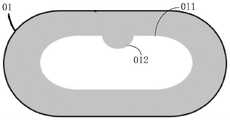
图1示出了一种全自动便携自拍眼底相机,该相机包括面贴组件01、运动组件、定位组件03和镜筒1,镜筒1内部设有照明组件、调焦组件、镜头(接目物镜)以及光学镜片组和成像探测器10等,镜筒1的内部结构可参考中国专利文件CN111134616A。实际产品还包括壳体,运动组件和镜筒1位于壳体内部。面贴组件01密封地连接于壳体的前部,面贴组件包括面贴本体和成型于面贴本体的用于被拍摄者的眼部贴合时容纳所述眼部的视窗通孔。面贴组件01作为接触被拍摄者眼部的部件,镜筒1透过面贴组件01的通孔采集被拍摄者的眼底视网膜图像。Figure 1 shows a fully automatic portable self-portrait fundus camera. The camera includes a
面贴本体背向镜筒1的一面被构造为与被拍摄者的眼部周围的面部轮廓相贴合的形状。具体地,面贴组件01向内形成凹陷形状以适于人体头部弧形,其通孔的尺寸至少能在被测者的眼部贴合本组件时容纳双眼。面贴组件01向内(壳体内、镜筒)的一面有至少一个用于检测相机各项功能的特定位置。在一个具体的实施例中,结合图1和图2所示,图2所展示的是面贴组件01朝内的一面,通孔011的中部上边缘有一个凸起部012,镜筒1的镜头能够对准此部位并拍摄图像。更优选的方案是,在此凸起部012上设置一个图案或者简单图形等作为标靶。此特定位置有多种用途,包括检测相机的照明组件、调焦组件是否正常,检测被拍者的眼部是否正确地贴合了面贴组件01等,具体将在下文中进行详细介绍。The side of the face sticker body facing away from the
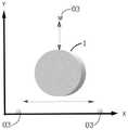
运动组件用于控制镜筒1在三维空间中移动,以图1中的坐标系为例,能够在图中的X、Y、Z三轴上移动。需要说明的是,镜筒1在Z方向移动到极限位置时,端部不会伸出面贴组件01外。作为一个具体的实施例,运动组件包括三个轨道组件,第一组轨道021用于控制镜筒1在X轴上的运动、第二组轨道022用于控制镜筒1在Y轴上的运动、图中未示出的第三组轨道用于控制镜筒1在Z轴上的运动。具体地,镜筒1连同第二组轨道022被设置在一个平台(基座)上,第一组轨道021能够带动基座整体运动,第三组轨道能够带动基座和第一组轨道021运动,使整体接近或远离面贴组件01。The motion component is used to control the movement of the
定位组件03用于检测镜筒1的移动情况。具体地,定位组件03可以是电磁感应器,根据电磁感应信号感知镜筒1移动到定位组件03所在的位置。结合图3所示,在本实施例中设置3个定位组件03,其中两个定位组件设置在可移动基座两侧,以检测镜筒1在X轴上的移动,第三个定位组件设置在该基座上,以检测镜筒1在Y轴上的移动,即定位组件03用于检测镜筒1在XY平面内的移动情况。The
根据本发明提供的眼底相机,用于成像的照明组件、调焦组件、接目物镜、光学镜片组和成像探测器集成在一个镜筒中实现光路结构小型化,减小眼底相机的体积,提高便携性;眼底相机的面贴组件设有用于容纳被拍摄者眼部的视窗通孔,用户可以自行佩戴眼底相机,将眼部置于视窗通孔位置,运动组件驱动镜筒在视窗通孔范围中搜索瞳孔,并调整工作距离,从而拍摄眼底图像,本方案降低了眼底相机硬件的复杂度和使用难度,让用户能够自主拍摄眼底图像,促进眼底相机的普及。According to the fundus camera provided by the present invention, the illumination component for imaging, the focusing component, the objective lens, the optical lens group and the imaging detector are integrated in one lens barrel to realize the miniaturization of the optical path structure, reduce the volume of the fundus camera, and improve the portability. The surface mount component of the fundus camera is provided with a window through hole for accommodating the eye of the photographed subject. The user can wear the fundus camera by himself, and place the eye at the position of the window through hole, and the motion component drives the lens barrel in the window through hole range. It searches the pupil and adjusts the working distance to capture the fundus image. This solution reduces the complexity and difficulty of the fundus camera hardware, allows users to shoot fundus images independently, and promotes the popularization of fundus cameras.
本发明实施例提供一种眼底图像全自动拍摄方法,该方法可以由眼底相机本身来执行,也可以由计算机或者服务器等电子设备执行(作为一种控制方法),该方法包括如下步骤:An embodiment of the present invention provides a fully automatic method for capturing a fundus image. The method can be executed by the fundus camera itself, or executed by an electronic device such as a computer or a server (as a control method), and the method includes the following steps:
S300,移动眼底相机镜头对准瞳孔。S300, move the lens of the fundus camera to aim at the pupil.
S400,控制镜头接近眼球并采集图像,该图像是对角膜所反射的照明光束的成像。S400, control the lens to approach the eyeball and capture an image, where the image is an imaging of the illumination beam reflected by the cornea.
S500,利用上述图像确定工作距离。S500, using the above image to determine the working distance.
S600,调整焦距并采集眼底图像,利用眼底图像确定拍摄焦距。S600, adjust the focal length and collect a fundus image, and use the fundus image to determine the shooting focal length.
S700,在工作距离上使用拍摄焦距拍摄眼底图像。For S700, fundus images were captured using the capture focal length at the working distance.
在优选的实施例中,在上述步骤S100之前还可以执行检测相机状态和用户使用状态的步骤,本方法还可以包括:In a preferred embodiment, before the above step S100, the step of detecting the camera state and the user's use state may also be performed, and the method may further include:
S100,检测眼底相机的运动组件、照明组件和调焦组件是否正常。此步骤作为可选操作,可以在眼底相机开机时执行。如果检测到某部件异常将终止后续拍摄操作并进行相应的异常提示。S100, detecting whether the motion components, lighting components and focusing components of the fundus camera are normal. This step is optional and can be performed while the fundus camera is turned on. If an abnormality of a component is detected, the subsequent shooting operation will be terminated and a corresponding abnormality prompt will be given.
S200,检测人体头部是否贴合眼底相机的面贴组件。此步骤作为可选操作,如果检测到人体头部未贴合眼底相机的面贴组件,可以通过语音模块向用户进行提示,引导用户正确佩戴眼底相机。S200, detecting whether the head of the human body fits the face-sticking component of the fundus camera. This step is an optional operation. If it is detected that the human head does not fit the face-mounting component of the fundus camera, the user can be prompted through the voice module to guide the user to wear the fundus camera correctly.
在相机开始拍摄的时候,实际应用场景下的瞳孔和接目物镜是不会完全对齐的,这时候需要相机通过瞳孔在传感器的成像来判断镜头相对瞳孔的位置,然后把镜头移动到瞳孔的正前方,再进行拍摄。针对上述步骤S300,本发明实施例提供一种眼底相机镜头自动对准方法,该方法可以由眼底相机本身来执行,也可以由计算机或者服务器等电子设备执行(作为一种控制方法),该方法包括如下步骤:When the camera starts to shoot, the pupil and the eyepiece objective lens in the actual application scene will not be completely aligned. At this time, the camera needs to judge the position of the lens relative to the pupil through the imaging of the pupil on the sensor, and then move the lens to the positive position of the pupil. ahead, and then shoot. For the above-mentioned step S300, an embodiment of the present invention provides a method for automatically aligning a lens of a fundus camera, which can be performed by the fundus camera itself, or performed by an electronic device such as a computer or a server (as a control method). It includes the following steps:
S1,对眼底相机镜头采集的图像进行识别,判断其中是否存在瞳孔。具体地,当用户佩戴上述眼底相机后,系统会连续(比如逐帧地)采集瞳孔的图像,如果能够在图像中识别到瞳孔,说明瞳孔已经在成像范围内,在此情况下进行微调以使镜头完全对准瞳孔即可进行拍摄。如果不能在图像中识别到瞳孔,则说明镜头与瞳孔位置偏差较大,原因可能是镜头的初始位置不合适,或者用户佩戴方式不标准等等。S1, identify the image collected by the lens of the fundus camera, and determine whether there is a pupil in it. Specifically, after the user wears the above-mentioned fundus camera, the system will continuously (such as frame by frame) capture images of the pupil. If the pupil can be identified in the image, it means that the pupil is already within the imaging range. In this case, fine-tuning is performed to make The lens is perfectly aligned with the pupil to shoot. If the pupil cannot be identified in the image, it means that the position of the lens and the pupil has a large deviation. The reason may be that the initial position of the lens is not suitable, or the user's wearing method is not standard, etc.
在图像中识别瞳孔影像的方式有多种,例如可以使用机器视觉算法,根据图像中的图形特征检测瞳孔轮廓和位置。然而,由于眼底相机在最终拍摄之前是使用红外光进行照明,因此瞳孔的成像不会非常清晰,同时角膜的反光也很给瞳孔检测带来很多困难,计算机视觉算法遇到这种情况很容易误判,因此在一个优选的实施例中使用深度学习算法来解决这个问题。There are many ways to identify pupil images in images, for example, machine vision algorithms can be used to detect pupil contours and positions based on graphical features in the image. However, since the fundus camera uses infrared light for illumination before the final shooting, the image of the pupil will not be very clear, and the reflection of the cornea also brings a lot of difficulties to the pupil detection, and the computer vision algorithm is easily mistaken in this situation. Therefore, in a preferred embodiment, a deep learning algorithm is used to solve this problem.
首先采集大量瞳孔的照片,这些照片是不同人、在距离上述眼底相机的接目物镜不同方向和距离、不同时间采集到的图像。然后在对每一张图像中的瞳孔进行标注,由此得到用于训练神经网络的训练数据。使用这些标注好的数据来训练一个神经网络模型(比如YOLO网络),经过训练后,神经网络模型的识别结果包括一个检测框,用于表征图像中瞳孔的位置和尺寸。First, a large number of photos of pupils are collected. These photos are images collected by different people, at different directions and distances from the eyepiece objective of the above-mentioned fundus camera, and at different times. Then, the pupils in each image are marked to obtain training data for training the neural network. Use these labeled data to train a neural network model (such as the YOLO network). After training, the recognition result of the neural network model includes a detection box, which is used to characterize the position and size of the pupil in the image.
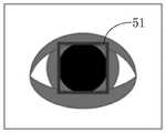
如图5所示,在一个具体的实施例中,训练数据中采用方形框51来标注瞳孔,训练后的神经网络模型的识别结果也将是方形检测框。在其它实施例中,也可以使用圆形框进行标注,或者其它类似的标注方式都是可行的。As shown in FIG. 5 , in a specific embodiment, a
无论采用何种瞳孔检测方法,在此步骤中只需要识别图像中是否存在瞳孔即可,如果图像中不存在瞳孔则执行步骤S2,否则执行步骤S3。No matter what kind of pupil detection method is adopted, in this step, it is only necessary to identify whether there is a pupil in the image, and if there is no pupil in the image, step S2 is performed, otherwise, step S3 is performed.
S2,控制眼底相机镜头在当前位置附近进行移动以搜索瞳孔。通过上述运动组件移动镜筒,例如做螺旋状轨迹移动,从当前位置开始逐渐向周围扩散。需要说明的是,本实施例只涉及到上述XY平面内的移动,暂时不论述Z轴的移动,Z轴的移动关系到眼底相机的最佳工作距离,具体将在后续的实施例中进行介绍。S2, control the lens of the fundus camera to move around the current position to search for the pupil. The lens barrel is moved by the above-mentioned motion components, for example, moving in a spiral trajectory, gradually spreading from the current position to the surroundings. It should be noted that this embodiment only involves the movement in the above-mentioned XY plane, and does not discuss the movement of the Z axis for the time being. The movement of the Z axis is related to the optimal working distance of the fundus camera, which will be introduced in the following embodiments. .
如果移动到极限位置后仍不能搜索到瞳孔,则提示用户调整佩戴状态;如果搜索到瞳孔,进一步判断如果用户的眼部是否偏离镜头很远,超出了运动组件能够移动的范围,比如判断镜头的移动距离是否超过移动阈值,当移动距离超过移动阈值时提示用户在面贴组件内轻微移动头部,以适应镜头的移动范围。然后继续搜索,当移动距离未超过移动阈值时执行步骤S3。If the pupil cannot be searched after moving to the limit position, the user will be prompted to adjust the wearing state; if the pupil is searched, it will be further judged if the user's eyes are far away from the lens, beyond the range that the motion component can move, such as judging the lens Whether the moving distance exceeds the moving threshold, when the moving distance exceeds the moving threshold, the user is prompted to move the head slightly in the face sticker component to adapt to the moving range of the lens. Then continue searching, and execute step S3 when the moving distance does not exceed the moving threshold.
S3,判断图像中的瞳孔是否符合设定条件。具体可设置多种设定条件,比如关于尺寸的条件、关于形状的条件等。S3, determine whether the pupil in the image meets the set condition. Specifically, a variety of setting conditions can be set, such as conditions related to size, conditions related to shape, and the like.
在一个可选的实施例中,设定条件包括尺寸阈值,判断图像中的瞳孔尺寸是否大于尺寸阈值,当图像中的瞳孔尺寸大于尺寸阈值时,判定存在符合设定条件的瞳孔;否则提示用户闭眼休息一段时间,使瞳孔放大之后再开始拍摄。因为拍摄眼底图像时一般是需要依次对双眼进行拍摄,对第一只眼拍摄之后会导致瞳孔缩小,因此系统也会让用户闭眼休息,让瞳孔大小恢复。In an optional embodiment, the set condition includes a size threshold, and it is determined whether the pupil size in the image is larger than the size threshold. When the pupil size in the image is larger than the size threshold, it is determined that there is a pupil that meets the set condition; otherwise, the user is prompted. Close your eyes and rest for a while to dilate your pupils before shooting. Because when taking fundus images, it is generally necessary to take pictures of both eyes in sequence. After taking the first eye, the pupil will be reduced. Therefore, the system will also let the user close their eyes and rest to restore the pupil size.
在另一个可选的实施例中,设定条件包括形态特征,判断图像中的瞳孔形状是否符合设定的形态特征,当图像中的瞳孔形状符合设定的形态特征时,判定存在符合设定条件的瞳孔;否则提示用户睁大眼睛、尽量不要眨眼等等。设定的形态特征为圆形或者近似圆形,如果检测出来的瞳孔不符合预设的形态特征,比如可能是扁平的,这种情况一般是因为用户眼睛没有睁开所导致的。In another optional embodiment, the set condition includes a morphological feature, and it is determined whether the pupil shape in the image conforms to the set morphological feature. Conditioned pupil; otherwise prompt the user to open their eyes, try not to blink, etc. The set morphological feature is circular or approximately circular. If the detected pupil does not conform to the preset morphological feature, for example, it may be flat, which is generally caused by the user's eyes not being opened.
在第三个可选的实施例中,需要使用上述神经网络模型进行瞳孔检测,并且神经网络模型的识别结果还包括瞳孔的置信度信息,也即用于表示模型判定图像中存在瞳孔的概率值。所述设定条件包括置信度阈值,判断神经网络模型得到的置信度信息是否大于所述置信度阈值。当所述置信度信息大于置信度阈值时,判定存在符合设定条件的瞳孔;否则提示用户睁大眼睛,移除头发等遮挡物。神经网络模型得到的瞳孔的置信度比较低,说明图像中虽然存在瞳孔但其可能被其它物体所干扰,为了提高拍摄质量,在此提示用户进行调整。In a third optional embodiment, the above-mentioned neural network model needs to be used for pupil detection, and the recognition result of the neural network model also includes the confidence information of the pupil, that is, the probability value used to indicate that the model determines that the pupil exists in the image . The setting conditions include a confidence threshold, and it is determined whether the confidence information obtained by the neural network model is greater than the confidence threshold. When the confidence information is greater than the confidence threshold, it is determined that there are pupils that meet the set conditions; otherwise, the user is prompted to open their eyes and remove obstacles such as hair. The confidence of the pupil obtained by the neural network model is relatively low, indicating that although there is a pupil in the image, it may be disturbed by other objects. In order to improve the shooting quality, the user is prompted to make adjustments here.
上述三种实施例可以被择一使用,也可以组合使用。当图像中的瞳孔符合设定条件时执行步骤S4,否则等待用户的调整自身状态并持续判断直至符合设定条件。The above three embodiments can be used alternatively or in combination. Step S4 is performed when the pupil in the image meets the set condition, otherwise, it waits for the user to adjust his state and continues to judge until the set condition is met.
S4,根据瞳孔在图像中的位置移动眼底相机镜头对准瞳孔。通过上述运动组件移动镜筒,移动方向和距离取决于图像中的瞳孔与镜头的偏差。将采集的图像中心点视为镜头的中心点,并识别图像中瞳孔的中心点。关于识别图像中瞳孔的中心点的方式,比如在使用上述神经网络模型检测瞳孔时,将检测框的中心点视为瞳孔的中心点即可。步骤S4具体包括:S4, move the lens of the fundus camera to align the pupil according to the position of the pupil in the image. The lens barrel is moved by the above-mentioned motion components, and the direction and distance of the movement depends on the deviation of the pupil from the lens in the image. Consider the center point of the acquired image as the center point of the lens, and identify the center point of the pupil in the image. Regarding the method of identifying the center point of the pupil in the image, for example, when the above-mentioned neural network model is used to detect the pupil, the center point of the detection frame may be regarded as the center point of the pupil. Step S4 specifically includes:
S41,根据检测框的中心位置和所述图像的中心位置的偏差确定移动距离和移动方向;S41, determine the moving distance and the moving direction according to the deviation of the center position of the detection frame and the center position of the image;
S42,根据确定的移动距离和移动方向移动眼底相机镜头对准瞳孔。S42, move the lens of the fundus camera to align the pupil according to the determined moving distance and moving direction.
根据本发明实施例提供眼底图像拍摄方法,通过对图像中的瞳孔状态进行判断,可以自动确定被拍者当前的瞳孔状态是否适合拍摄眼底图像,在其状态不适于拍摄眼底图像时,可以向被拍者发出相应的提示以使其调整自身的状态,在其状态适合拍摄眼底图像时,识别瞳孔的位置从而进行自动对准,之后进行拍摄,由此避免拍摄到不可用的眼底图像,整个过程不需要专业人员参与,实现用户自主拍摄。According to an embodiment of the present invention, a fundus image capturing method is provided. By judging the pupil state in the image, it can be automatically determined whether the subject's current pupil state is suitable for capturing the fundus image. The photographer sends out corresponding prompts to adjust their own state. When the state is suitable for shooting fundus images, the position of the pupil is recognized to perform automatic alignment, and then the shooting is performed, thereby avoiding unusable fundus images. The whole process No professional participation is required, enabling users to shoot autonomously.
在实际应用场景中,可能出现一种特别的情况,即瞳孔的尺寸可能小于环状照明光束的尺寸,在此情况下将瞳孔和接目物镜对齐会导致没有任何光线能进入瞳孔,因此拍摄出来的图像是黑的。In practical application scenarios, there may be a special situation where the size of the pupil may be smaller than the size of the annular illumination beam. In this case, aligning the pupil with the eyepiece will cause no light to enter the pupil, so the image is captured. The image is black.
为了解决这一问题,针对上述步骤S700,本发明实施例提供一种优选的眼底图像拍摄方法,本方法包括如下步骤:In order to solve this problem, for the above step S700, an embodiment of the present invention provides a preferred method for capturing a fundus image, and the method includes the following steps:
S51,判断图像中的瞳孔尺寸是否小于眼底相机照明组件的环状照明光束尺寸。图7示出了一个瞳孔72尺寸大于环状光束71尺寸的情况,此情况下执行步骤S52。S51, determine whether the pupil size in the image is smaller than the annular illumination beam size of the fundus camera illumination assembly. FIG. 7 shows a case where the size of the
图8示出了两个环状照明光束尺寸大于瞳孔尺寸的情况,照明光源是一个完整的环形照明灯或者是由多个照明灯呈环状排列形成的光源,环状光束71的内径大于瞳孔72的直径。Fig. 8 shows the case where the size of the two annular illumination beams is larger than the pupil size. The illumination light source is a complete annular illumination lamp or a light source formed by a plurality of illumination lamps arranged in a ring shape. The inner diameter of the
当瞳孔尺寸小于环状照明光束尺寸时,即符合如图8所示情形时执行步骤S53。Step S53 is executed when the pupil size is smaller than the annular illumination beam size, that is, the situation as shown in FIG. 8 is met.
S52,以当前的镜头位置拍摄眼底图像。这是在光源良好地照射眼底的情况下所拍摄的图像。S52, taking a fundus image with the current lens position. This is an image taken when the light source is well illuminated on the fundus of the eye.
S53,分别向多个方向移动镜头与瞳孔产生偏移,使得环状照明光束部分照射在瞳孔中,并获取多个眼底图像。以图9所示移动为例,在本实施例中,分别向水平的两个方向移动镜头,当镜头向一侧移动后使得环状光束71的一部分73照射到瞳孔72中,此时拍摄一张眼底图像;当镜头向另一侧移动后使得环状光束71的另一部分74照射到瞳孔72中,此时拍摄另一张眼底图像。S53 , moving the lens and the pupil in multiple directions respectively to offset the pupil, so that the annular illumination light beam is partially irradiated in the pupil, and a plurality of fundus images are acquired. Taking the movement shown in FIG. 9 as an example, in this embodiment, the lens is moved in two horizontal directions, and when the lens is moved to one side, a
图9所示的移动和照明只是为了说明拍摄情况而做的举例,实际应用中可以向更多方向移动以拍摄更多的眼底图像。然而类似这种移动和照明情况下所拍摄的眼底图像会有部分区域出现过曝现象,这种眼底图像无法直接作为拍摄结果,因此执行步骤S54。The movement and illumination shown in FIG. 9 are only examples for illustrating the shooting situation. In practical applications, the movement in more directions can be used to shoot more fundus images. However, the fundus image captured under such moving and lighting conditions may have overexposure in some areas, and such a fundus image cannot be directly used as a shooting result, so step S54 is performed.
另外,为了减少过曝光的区域,在一个优选的实施例中,采用如下方式移动和拍摄:In addition, in order to reduce the overexposed area, in a preferred embodiment, the following methods are used to move and shoot:
S531,确定瞳孔的边缘位置。具体可使用机器视觉算法或者使用上述神经网络模型,得到图9中瞳孔72的左侧边缘点721和右侧边缘点722。S531, determine the edge position of the pupil. Specifically, a machine vision algorithm or the above-mentioned neural network model can be used to obtain the
S532,根据瞳孔的边缘位置确定移动距离。具体可根据当前镜头中心的位置O(图像中心位置)与左侧边缘点721和右侧边缘点722的位置关系计算运动组件的移动距离。S532: Determine the moving distance according to the edge position of the pupil. Specifically, the moving distance of the moving component can be calculated according to the positional relationship between the position O of the current lens center (image center position) and the
S533,按照确定的移动距离分别向多个方向移动所述镜头,所确定的移动距离使得环状照明光束的边缘与瞳孔的边缘位置重合。如图9所示,环状光束71的外圈边缘恰好与瞳孔72的边缘重合,这样可以使环状光束71进入眼底的部分位于眼底的边缘,减少对眼底中心区域成像的影响。S533 , respectively move the lens in multiple directions according to the determined moving distance, and the determined moving distance makes the edge of the annular illumination beam coincide with the edge of the pupil. As shown in FIG. 9 , the outer edge of the
S54,将多个眼底图像融合为一个眼底图像。在此步骤中,将分别从各个眼底图像中提取可用的区域,利用这些眼底图像拼接并融合出一张完整的眼底图像。拼接和融合的方式有多种,作为一个可选的实施例,步骤S54具体包括:S54, fuse the multiple fundus images into one fundus image. In this step, the available areas will be extracted from each fundus image, and a complete fundus image will be stitched and fused using these fundus images. There are many ways of splicing and fusion. As an optional embodiment, step S54 specifically includes:
S541a,根据获取的眼底图像对应的镜头移动距离计算多个眼底图像的位移偏差;S541a, calculating the displacement deviation of multiple fundus images according to the lens movement distances corresponding to the acquired fundus images;
S542a,在多个眼底图像中选取有效区域;S542a, selecting an effective area in multiple fundus images;
S543a,根据位移偏差对多个有效区域进行拼接,得到拼接后的眼底图像。进一步地,利用图像融合算法在各个所述有效区域的拼接处进行融合处理。S543a, splicing a plurality of effective areas according to the displacement deviation to obtain a spliced fundus image. Further, an image fusion algorithm is used to perform fusion processing at the splicing of each of the effective regions.
作为另一个可选的实施例,步骤S54具体包括:As another optional embodiment, step S54 specifically includes:
S541b,在多个眼底图像中检测相应的特征点;S541b, detecting corresponding feature points in multiple fundus images;
S542b,根据特征点的位置计算多个眼底图像的空间变换关系;S542b, calculating the spatial transformation relationship of the multiple fundus images according to the positions of the feature points;
S543b,根据空间变换关系将多个眼底图像设置在同一坐标系下;S543b, setting the multiple fundus images in the same coordinate system according to the spatial transformation relationship;
S544b,在处于同一坐标系下的多个眼底图像中选取有效区域进行拼接,得到拼接后的眼底图像。S544b, selecting an effective area from the multiple fundus images in the same coordinate system for splicing to obtain a stitched fundus image.
根据本发明实施例提供眼底图像拍摄方法,在眼底相机镜头对准瞳孔时,首先判断比较图像中的瞳孔尺寸和相机本身发出的环状光速的尺寸,如果瞳孔尺寸太小导致照明光束不能正常照射到眼底,则移动镜头,偏离当前的对准位置使得环状照明光束部分照射在瞳孔中,并在多个偏移位置上获取眼底图像,最终根据多个眼底图像融合出一个眼底图像,本方案可以在被拍者瞳孔较小的情况下拍摄眼底图像,不需要专业人员参与拍摄过程,降低对被拍摄者瞳孔状态的要求,提高拍摄效率。According to an embodiment of the present invention, a method for capturing a fundus image is provided. When the lens of the fundus camera is aligned with the pupil, the size of the pupil in the comparison image and the size of the annular speed of light emitted by the camera itself are first judged. If the pupil size is too small, the illumination beam cannot be illuminated normally. When reaching the fundus, the lens is moved to deviate from the current alignment position so that the annular illumination beam is partially illuminated in the pupil, and fundus images are acquired at multiple offset positions, and finally a fundus image is fused according to multiple fundus images. This scheme The fundus image can be taken when the pupil of the subject is small, without the need for professionals to participate in the shooting process, which reduces the requirements for the pupil state of the subject and improves the shooting efficiency.
下面介绍关于相机镜头(镜筒)在Z轴的移动,Z轴的移动关系到眼底相机的最佳工作距离。针对上述步骤S400-S500,本实施例提供一种眼底相机的工作距离调整方法,该方法可以由眼底相机本身来执行,也可以由计算机或者服务器等电子设备执行(作为一种控制方法)。该方法包括如下步骤:The following describes the movement of the camera lens (lens barrel) in the Z axis, which is related to the optimal working distance of the fundus camera. Aiming at the above steps S400-S500, this embodiment provides a method for adjusting the working distance of a fundus camera, which can be performed by the fundus camera itself, or performed by an electronic device such as a computer or a server (as a control method). The method includes the following steps:
S1,控制镜头接近眼球并采集图像,该图像是对角膜所反射的照明光束的成像。此步骤是根据上述实施例的方案,在XY平面内将镜头对准瞳孔的情况下被执行,此步骤中控制镜头接近眼球是指通过运动组件控制镜头在Z轴上向眼球的方向移动。在初始的距离上,照明组件的光源通过光学镜头,照射到眼睛角膜上的反射光在cmos上进行成像会得到如图10所示的结果,在本实施例中的光源是按十字形分布于照明组件四侧的四个灯球,对此光源的成像中也相应地显示出四个光斑。在其它实施例中,照明光源可以是如图8所示的形状,所采集的图像中将显示出相应形状或排列的光斑。S1, control the lens to approach the eyeball and capture an image, the image is the imaging of the illumination beam reflected by the cornea. This step is performed according to the solution of the above-mentioned embodiment and is performed when the lens is aligned with the pupil in the XY plane. In this step, controlling the lens to approach the eyeball means controlling the lens to move toward the eyeball on the Z axis through the motion component. At the initial distance, the light source of the illumination component passes through the optical lens, and the reflected light irradiated on the cornea of the eye is imaged on the cmos, and the result shown in Figure 10 will be obtained. In this embodiment, the light source is distributed in a cross shape at The four light balls on the four sides of the lighting assembly also show four light spots in the imaging of this light source. In other embodiments, the illumination light source may be in the shape as shown in FIG. 8 , and the captured image will show light spots of corresponding shape or arrangement.
S2,检测图像中的光斑的特征是否符合设定特征。如图11所示,随着镜筒1在Z轴上向眼球01移动,角膜反射光成像将会发生变化。具体来说,成像的位置、尺寸和清晰度,与接目物镜和角膜之间的距离相关。距离越近,入射光线和角膜的法线夹角越大,反射的散射效果更重,光斑尺寸越大、越发散、亮度越低。S2, detecting whether the features of the light spots in the image conform to the set features. As shown in FIG. 11 , as the
在图像中识别光斑特征的方式有多种,例如可以使用机器视觉算法,根据图像中的图形特征检测光斑轮廓和位置。然而,由于光斑的清晰度、尺寸等各方面的变化范围较大,计算机视觉算法遇到这种情况很容易误判,因此在一个优选的实施例中使用深度学习算法来解决这个问题。There are many ways to identify the light spot features in an image. For example, machine vision algorithms can be used to detect the contour and position of the light spot based on the graphic features in the image. However, due to the wide variation range of the sharpness and size of the light spot, the computer vision algorithm is prone to misjudgment in this situation. Therefore, in a preferred embodiment, a deep learning algorithm is used to solve this problem.
首先采集大量光斑的成像,这些成像是不同人、在距离上述眼底相机的接目物镜不同方向和距离、不同时间采集到的图像。然后在对每一张图像中的光斑进行标注,由此得到用于训练神经网络的训练数据。使用这些标注好的数据来训练一个神经网络模型(比如YOLO网络),经过训练后,神经网络模型的识别结果包括一个检测框,用于表征图像中光斑的位置和尺寸。First, images of a large number of light spots are collected, and these images are images collected by different people at different directions and distances from the eyepiece objective of the above-mentioned fundus camera and at different times. Then, the light spots in each image are marked to obtain training data for training the neural network. Use these labeled data to train a neural network model (such as the YOLO network). After training, the recognition result of the neural network model includes a detection frame, which is used to characterize the position and size of the light spot in the image.
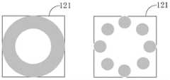
如图12所示,在一个具体的实施例中,训练数据中采用方形框121来标注光斑,训练后的神经网络模型的识别结果也将是方形检测框。在其它实施例中,也可以使用圆形框进行标注,或者其它类似的标注方式都是可行的。As shown in FIG. 12 , in a specific embodiment, a
无论采用何种光斑检测方法,在此步骤中识别到当前图像中的光斑特征符合设定特征即可。所述设定特征可以是关于尺寸的特征,比如当图像中的光斑尺寸小于设定尺寸时判定符合设定特征;也可以是光斑消失,比如当使用机器视觉算法或者神经网络不能检测到图像中的光斑时判定符合设定特征。No matter what kind of spot detection method is adopted, in this step, it is only necessary to recognize that the spot feature in the current image conforms to the set feature. The set feature can be a feature about size, for example, when the spot size in the image is smaller than the set size, it is determined to meet the set feature; it can also be the disappearance of the spot, such as when the machine vision algorithm or neural network cannot detect the image in the image. It is judged that the light spot conforms to the set characteristics.
如果图像中的光斑符合设定特征则执行步骤S3,否则返回步骤S1,继续移动镜头并采集图像。If the light spot in the image conforms to the set characteristics, step S3 is performed; otherwise, it returns to step S1 to continue to move the lens and capture images.
S3,确定达到工作距离。在确定图像中光斑的特征符合设定特征时,此时镜头与眼球之间的距离可以被视为达到工作距离。在具体的实施例中,根据硬件参数,还可以在此距离的基础上再进行一个距离补偿,补偿的方向、距离值与硬件参数有关。作为举例,图13示出了一个光斑符合设定特征的图像,此时镜头1与眼球01的距离为WD,在此基础上控制镜头继续向接近眼球的方向移动预设距离d,以达到更准确的工作距离WD+。S3, it is determined that the working distance is reached. When it is determined that the characteristics of the light spot in the image conform to the set characteristics, the distance between the lens and the eyeball at this time can be regarded as reaching the working distance. In a specific embodiment, according to the hardware parameters, another distance compensation may be performed on the basis of the distance, and the direction and distance value of the compensation are related to the hardware parameters. As an example, Figure 13 shows an image with the light spot conforming to the set characteristics. At this time, the distance between the
在此工作距离上,进一步调整焦距即可拍摄眼底图像。关于调整焦距的方式,具体将在后续的实施例中进行介绍。At this working distance, a further adjustment of the focal length allows a fundus image to be captured. The way of adjusting the focal length will be specifically introduced in the following embodiments.
根据本发明实施例提供的工作距离调整方法,对角膜所反射的照明光束的成像进行采集和识别,通过图像中的光斑特征来判断和调整镜头与眼球的距离,不需要在眼底相机上设置任何额外的光学或者硬件,只需要设置合适的照明光束即可实现准确定位工作距离,由此可以降低眼底相机的成本,并提高工作距离调整效率。According to the working distance adjustment method provided by the embodiment of the present invention, the imaging of the illumination beam reflected by the cornea is collected and identified, and the distance between the lens and the eyeball is judged and adjusted according to the light spot feature in the image, and it is not necessary to set any setting on the fundus camera. With additional optics or hardware, it is only necessary to set an appropriate illumination beam to accurately locate the working distance, thereby reducing the cost of the fundus camera and improving the efficiency of working distance adjustment.
考虑到镜头向眼球方向移动的过程中,用户可能会轻微转动头部等等,这将导致镜头不再是对准瞳孔的状态,因此在调整工作距离的过程中,还将在XY平面上调整镜头的位置以保持对准瞳孔。本实施例提供一种优选的调整工作距离的方法,该方法包括如下步骤:Considering that in the process of moving the lens to the direction of the eyeball, the user may slightly turn the head, etc., which will cause the lens to no longer be aligned with the pupil. Therefore, during the adjustment of the working distance, it will also be adjusted on the XY plane. Position the lens to keep the pupil aligned. This embodiment provides a preferred method for adjusting the working distance, and the method includes the following steps:
S1A,采集角膜所反射的照明光束的成像;S1A, capture the imaging of the illumination beam reflected by the cornea;
S2A,调用神经网络对图像中的光斑进行检测,判断图像中是否存在光斑。当图像中不存在光斑时执行步骤S6A,否则执行步骤S3A。S2A, call the neural network to detect the light spot in the image, and judge whether there is a light spot in the image. When there is no light spot in the image, step S6A is performed, otherwise, step S3A is performed.
S3A,识别图像中光斑的中心点,并判断光斑的中心点与图像的中心点是否重合。在此将神经网络得到的检测框的中心视为光斑的中心。图像的中心点被视为镜头的中心,如果图像的中心点与光斑中心重合则表示镜头对准了瞳孔,执行步骤S5A;二者不重合则表示镜头偏离的对准位置,执行步骤S4A。S3A: Identify the center point of the light spot in the image, and determine whether the center point of the light spot coincides with the center point of the image. Here, the center of the detection frame obtained by the neural network is regarded as the center of the light spot. The center point of the image is regarded as the center of the lens. If the center point of the image coincides with the center of the light spot, it means that the lens is aligned with the pupil, and step S5A is performed;
S4A,根据光斑的中心点与图像的中心点的偏移量微调镜头位置。检测-调整-再检测是一个反馈过程,作为一个优选的实施例,在此使用一种平滑的调整算法:S4A, fine-tune the lens position according to the offset of the center point of the light spot and the center point of the image. Detection-adjustment-re-detection is a feedback process. As a preferred embodiment, a smooth adjustment algorithm is used here:
Adjustment(i)=a*Shift(i)+(1-a)Adjustment(i-1),Adjustment(i)=a*Shift(i)+(1-a)Adjustment(i-1),
其中Adjustment(i-1)表示上一次镜头调整的位移,Shift(i)表示所述偏移量(瞳孔中心和图像中心的偏差),Adjustment(i)表示本次镜头需要调整的位移,a为0-1之间的系数。因为镜头的位置是XY平面上的二维坐标,Adjustment和Shift都是二维向量。Among them, Adjustment(i-1) represents the displacement of the last lens adjustment, Shift(i) represents the offset (the deviation between the pupil center and the image center), Adjustment(i) represents the displacement that needs to be adjusted this time, and a is A coefficient between 0-1. Because the position of the lens is a two-dimensional coordinate on the XY plane, both Adjustment and Shift are two-dimensional vectors.
将光斑的中心点与图像的中心点调整至重合后,执行步骤S5A。After the center point of the light spot is adjusted to coincide with the center point of the image, step S5A is performed.
S5A,控制镜头向接近眼球的方向移动,以缩小距离。之后返回步骤S1A,随着反复执行使镜头逐渐接近眼球,相应的图像中的光斑尺寸由大变小。为了精确地捕捉到光斑消失的临界点,可以对每一帧图像进行采集并相应地做出上述判断和调整,直到检测到光斑消失的图像为止。S5A, control the lens to move closer to the eyeball to reduce the distance. Then, returning to step S1A, with the repeated execution of making the lens gradually approach the eyeball, the size of the light spot in the corresponding image changes from large to small. In order to accurately capture the critical point of the disappearance of the light spot, each frame of image can be collected and the above judgment and adjustment can be made accordingly until the image of the disappearance of the light spot is detected.
S6A,控制镜头继续向接近眼球的方向移动预设距离,以达到工作距离。S6A, control the lens to continue to move the preset distance in the direction close to the eyeball to reach the working distance.
在优选的实施例中,在执行上述调整过程的同时,还将检测图像中的光斑是否完整,当光斑不完整时,比如只有一半,这意味着用户在眨眼或者眼睛没有睁开,此时系统会通过语音提示用户睁大眼,尽量不要眨眼等等。In a preferred embodiment, while performing the above adjustment process, it will also detect whether the light spot in the image is complete. When the light spot is incomplete, such as only half of it, it means that the user is blinking or his eyes are not open. At this time, the system It will prompt the user to open their eyes by voice, try not to blink, etc.
根据本发明实施例提供的工作距离调整方法,在调整镜头与眼球的距离的同时,还将根据图像中的光斑位置微调镜头位置,由此在调整工作距离时保持镜头对准瞳孔,本方案不需要在眼底相机上设置任何额外的光学或者硬件,只需要设置合适的照明光束即可实现准确定位工作距离并保持镜头对准瞳孔,由此可以降低眼底相机的成本,并提高眼底图像拍摄效率。According to the working distance adjustment method provided by the embodiment of the present invention, while adjusting the distance between the lens and the eyeball, the position of the lens is also fine-tuned according to the position of the light spot in the image, thereby keeping the lens aligned with the pupil when adjusting the working distance. It is necessary to set any additional optics or hardware on the fundus camera, and only need to set the appropriate illumination beam to achieve accurate positioning of the working distance and keep the lens aligned with the pupil, thereby reducing the cost of the fundus camera and improving the efficiency of fundus image capture.
通过上述实施例的自动对准和自动调整工作距离之后,还需要设置合适的焦距才能拍摄到清晰的眼底图像。下面介绍关于自动调整焦距的技术方案,针对上述步骤S600,本实施例提供一种眼底相机的焦距调整方法,该方法可以由眼底相机本身来执行,也可以由计算机或者服务器等电子设备执行(作为一种控制方法)。该方法包括如下步骤:After the automatic alignment and automatic adjustment of the working distance in the above embodiment, it is necessary to set an appropriate focal length to capture a clear fundus image. The following describes the technical solution for automatically adjusting the focal length. For the above step S600, this embodiment provides a method for adjusting the focal length of the fundus camera, which can be performed by the fundus camera itself, or by an electronic device such as a computer or a server (as a a control method). The method includes the following steps:
S1,调整焦距并采集眼底图像。此步骤在眼底相机镜头对准瞳孔并且达到工作距离时被执行,此时的镜头与眼球的位置如图13所示。需要说明的是,在上述实施例调整镜头位置和工作距离的过程中采集图像时,当然也需要设置固定的焦距,比如在调整工作距离时,焦距可以是固定调到0屈光位置。如果被拍摄者屈光正常,当工作距离调到位后,即可直接拍摄眼底图像。但实际应用时需要考虑被拍者的实际屈光度,从而设置适合的焦距。S1, adjust the focus and collect fundus images. This step is performed when the fundus camera lens is aligned with the pupil and reaches the working distance, and the position of the lens and the eyeball at this time is shown in Figure 13. It should be noted that, in the process of adjusting the lens position and the working distance in the above-mentioned embodiments, a fixed focal length needs to be set. If the subject's refraction is normal, when the working distance is adjusted in place, the fundus image can be taken directly. However, in practical application, it is necessary to consider the actual diopter of the person being photographed, so as to set a suitable focal length.
在眼底相机进行曝光拍摄眼底图像之前,比如上述自动对准和自动确定工作距离的过程中都是用红外光来成像,此时采集图像所使用的光源仍然是红外光。虽然当前的焦距不能使眼底清晰地成像,但在此时采集的图像已经能基本体现出眼底的特征,图像中至少可以显示出视盘,因此称采集的图像为眼底图像。Before the fundus camera performs exposure to capture the fundus image, for example, in the above-mentioned processes of automatic alignment and automatic determination of the working distance, infrared light is used for imaging. At this time, the light source used for capturing the image is still infrared light. Although the current focal length cannot make the fundus image clearly, the image collected at this time can basically reflect the characteristics of the fundus, and at least the optic disc can be displayed in the image, so the collected image is called the fundus image.
S2,在眼底图像中识别视盘区域。因为视盘区域是眼底中纹理最多、亮度最高的区域,因此最适合用于调焦。S2, identify the optic disc region in the fundus image. Because the optic disc area is the most textured and brightest area in the fundus, it is most suitable for focusing.
在眼底图像中识别视盘的方式有多种,例如可以使用机器视觉算法,根据眼底图像中的图形特征检测视盘轮廓和位置。然而,由于使用红外光成像相对模糊,给识别视盘带来很大的挑战,计算机视觉算法遇到这种情况很容易误判,因此在一个优选的实施例中使用深度学习算法来解决这个问题。There are many ways to identify the optic disc in the fundus image. For example, machine vision algorithms can be used to detect the contour and position of the optic disc based on the graphic features in the fundus image. However, because the use of infrared light imaging is relatively blurry, it brings great challenges to the identification of the optic disc, and the computer vision algorithm is prone to misjudgment in this situation. Therefore, in a preferred embodiment, a deep learning algorithm is used to solve this problem.
首先采集大量眼底图像,这些图像对不同的人、使用不同焦距所采集的眼底图像。然后对每一张图像中的视盘进行标注,由此得到用于训练神经网络的训练数据。使用这些标注好的数据来训练一个神经网络模型(比如YOLO网络),经过训练后,神经网络模型的识别结果包括一个检测框,用于表征眼底图像中视盘的位置。First, a large number of fundus images are collected, and these images are fundus images collected for different people using different focal lengths. The optic disc in each image is then annotated to obtain training data for training the neural network. Use these labeled data to train a neural network model (such as the YOLO network). After training, the recognition result of the neural network model includes a detection frame, which is used to represent the position of the optic disc in the fundus image.
如图14所示,在一个具体的实施例中,训练数据中采用方形框141来标注视盘,训练后的神经网络模型的识别结果也将是方形检测框。在其它实施例中,也可以使用圆形框进行标注,或者其它类似的标注方式都是可行的。As shown in FIG. 14 , in a specific embodiment, a
S3,根据视盘区域的清晰度确定拍摄焦距。具体地,可以从初始的焦距开始,采用梯度上升的方式不断变换焦距并采集相应的眼底图像,判断其中的视盘的清晰度是否达到预设标准,一旦达到预设标准,则判定当前的焦距为最佳焦距,不需要再继续搜索;也可以在焦距可调范围内使用所有可用的焦距,并采集相应的眼底图像,从所有眼底图像中确定一个视盘清晰度最高的眼底图像,判定采集该图像时的焦距为最佳焦距。S3, determining the shooting focal length according to the sharpness of the optic disc area. Specifically, starting from the initial focal length, the focal length can be continuously changed by means of gradient ascent and the corresponding fundus images can be collected to determine whether the clarity of the optic disc has reached the preset standard. The best focal length does not need to continue searching; you can also use all available focal lengths within the adjustable focal length range, and collect the corresponding fundus images, determine a fundus image with the highest optic disc definition from all fundus images, and decide to collect the image. The focal length at is the best focal length.
在一个具体的实施例中,采用遍历的方式,先在设定焦距范围800-1300内以第一设定步长40调整焦距并采集第一组眼底图像,由此到焦距800时的眼底图像、焦距840时的眼底图像、焦距880时的眼底图像……焦距1300时的眼底图像。分别在这些眼底图像中识别视盘区域,并分别确定每个眼底图像的清晰度,在本实施例中是计算视盘区域内的像素值的均值作为清晰度。然后可以从第一组眼底图像中确定一个具有最高清晰度的眼底图像,此时可以将采集该眼底图像时所使用的焦距X(第一焦距)作为拍摄焦距。In a specific embodiment, the traversal method is used to first adjust the focal length with a first set step size of 40 within the set focal length range of 800-1300, and collect the first group of fundus images, thus the fundus images when the focal length reaches 800 , the fundus image at the focal length of 840, the fundus image at the focal length of 880...the fundus image at the focal length of 1300. The optic disc area is identified in these fundus images respectively, and the sharpness of each fundus image is determined respectively. In this embodiment, the mean value of the pixel values in the optic disc area is calculated as the sharpness. Then, a fundus image with the highest definition can be determined from the first group of fundus images, and at this time, the focal length X (first focal length) used when collecting the fundus image can be taken as the shooting focal length.
为了取得更好的拍摄效果,还可进一步搜索焦距,比如在上述焦距X附近再进行一次遍历,在此次遍历过程中所使用的第二设定步长小于上述第一设定步长,比如第二设定步长为10,由此可以进一步得到第二组眼底图像,即焦距X+10时的眼底图像、焦距X+20时的眼底图像、X-10时的眼底图像、X-20时的眼底图像等等。然后再分别在这些眼底图像中识别视盘区域,并分别确定每个眼底图像的清晰度,比如确定焦距X-20时的眼底图像为清晰度最高的眼底图像,则将焦距X-20(第二焦距)作为拍摄焦距。In order to obtain a better shooting effect, you can further search for the focal length, for example, perform another traversal near the above-mentioned focal length X, and the second set step size used in this traversal process is smaller than the above-mentioned first set step size, such as The second set step size is 10, so that the second group of fundus images can be obtained, namely, the fundus images at the focal length of X+10, the fundus images at the focal length of X+20, the fundus images at the time of X-10, and the fundus images at the time of X-20 fundus images, etc. Then, identify the optic disc area in these fundus images respectively, and determine the clarity of each fundus image. focal length) as the shooting focal length.
关于进一步搜索焦距的范围,作为优选的实施例,可将第一焦距X为中点,以增大第一设定步长为最大值、以减小第一设定步长为最小值的焦距范围,范围是X±40。Regarding the range of further searching for the focal length, as a preferred embodiment, the first focal length X can be taken as the midpoint to increase the focal length of the first set step size to the maximum value and to decrease the focal length of the first set step size to the minimum value range, the range is X±40.
根据本发明实施例提供的焦距调整方法,在不同焦距下采集眼底图像,通过眼底图像中的视盘清晰度判断当前的焦距是否适用于拍摄眼底图像,不需要在眼底相机上设置任何额外的光学或者硬件,只需要设置图像识别算法即可找到最佳的对焦位置,由此可以降低眼底相机的成本,并提高焦距调整效率。According to the focal length adjustment method provided by the embodiment of the present invention, fundus images are collected at different focal lengths, and whether the current focal length is suitable for capturing fundus images is judged by the clarity of the optic disc in the fundus images. Hardware, only need to set the image recognition algorithm to find the best focus position, which can reduce the cost of the fundus camera and improve the efficiency of focus adjustment.
考虑到调整焦距的过程中用户可能会轻微转动头部等等,这将导致镜头不再是对准瞳孔的状态,因此在调整焦距的过程中,还将在XY平面上调整镜头的位置以保持对准瞳孔。并且,进行到此阶段时已经即将要拍摄眼底图像,如果被拍摄者在此时眨眼或者闭眼将无法成功拍摄,所以在此过程中还需要进行眨眼和/或闭眼的检测。本实施例提供一种优选的焦距调整方法,该方法包括如下步骤:Considering that the user may slightly turn the head during the process of adjusting the focus, etc., which will cause the lens to no longer be aligned with the pupil, so during the process of adjusting the focus, the position of the lens will also be adjusted on the XY plane to keep the Align the pupil. Moreover, when the fundus image is about to be taken at this stage, if the subject blinks or closes his eyes at this time, the shooting will not be successful. Therefore, during this process, eye blinking and/or eye closing detection needs to be performed. This embodiment provides a preferred focal length adjustment method, which includes the following steps:
S1A,利用当前的焦距采集眼底图像。S1A, use the current focal length to acquire a fundus image.
S2A,通过眼底图像判断被拍摄者是否眨眼和/或闭眼。当被拍摄者眨眼和/或闭眼时进行提示,比如通过语音提示用户不要眨眼或闭眼等等,然后返回步骤S1A;否则执行步骤S3A。眨眼和闭眼检测也可以通过机器视觉算法或者神经网络算法实现,当被拍摄者眨眼或者闭眼时,采集的图像将是全黑或者非常模糊的,特征相对明显,可以采用多种方法进行检测,此处不再赘述。S2A, it is judged whether the subject blinks and/or closes his eyes according to the fundus image. When the subject blinks and/or closes his eyes, a prompt is given, for example, a voice prompts the user not to blink or close his eyes, etc., and then return to step S1A; otherwise, step S3A is performed. Eye blinking and eye closing detection can also be realized by machine vision algorithm or neural network algorithm. When the subject blinks or closes his eyes, the collected image will be completely black or very blurry, and the features are relatively obvious. Various methods can be used for detection. , and will not be repeated here.
S3A,识别眼底图像中是否存在由角膜所反射的照明光束形成的光斑。与上述实施例调整工作距离时保持镜头对准瞳孔的方式不同,在达到工作距离后,如果是对准的状态,角膜反射的照明光束应当不在成像范围内,眼底图像中不应该再出现上述光斑,尤其是不可能出现光斑的完整成像。即使出现光斑也将是整个光斑的一部分,在一个具体实施例中使用由多个照明灯呈环状排列形成的光源,完整的光斑如图12所示。如果在调整焦距时眼底图像中出现光斑,将是如图15所示的情况,其中只有部分光斑151。如果光源本身是一个完整的环形灯,则在图像中此出现带状物。S3A, identifying whether there is a light spot formed by the illumination beam reflected by the cornea in the fundus image. Different from the method of keeping the lens aligned with the pupil when adjusting the working distance in the above embodiment, after reaching the working distance, if it is in the aligned state, the illumination beam reflected by the cornea should not be in the imaging range, and the above-mentioned light spot should not appear in the fundus image. , especially the complete imaging of the spot is not possible. Even if a light spot appears, it will be a part of the whole light spot. In a specific embodiment, a light source formed by a plurality of illumination lamps arranged in a ring shape is used, and the complete light spot is shown in FIG. 12 . If a light spot appears in the fundus image when the focus is adjusted, it will be the situation as shown in FIG. 15 , in which there is only a part of the
当眼底图像中存在光斑时,执行步骤S4A,否则执行步骤S5A。When there is a light spot in the fundus image, step S4A is performed, otherwise, step S5A is performed.
S4A,至少根据光斑的位置微调镜头位置,以移除光斑,从而保持镜头对准瞳孔。当光斑出现在不同位置时,其尺寸和亮度会有所不同。作为优选的实施例,结合光斑在图像中的位置、尺寸和亮度可计算出矢量偏移。以图15为例,将图像中心作为原点(0,0)建立坐标系,图像半径为R。计算各个光斑151的近似圆形区域,在本实施例中近似圆区域是包含光斑151的最小圆形区域。比如第i个光斑的近似圆形区域的中心坐标为(xi,yi),半径是ri。那么可以得出第i个光斑需要移动的方向是vi=(xi,yi),需要移动的距离是
再次使镜头对准瞳孔后返回步骤S1A。After aligning the lens with the pupil again, the process returns to step S1A.
S5A,在眼底图像中识别视盘区域,判断视盘区域的清晰度是否达到设定标准。在本实施例中使用mobilenet-yolov3神经网络模型识别视盘,神经网络输出的视盘区域是包含视盘和背景的区域。然后通过边缘检测算法(如sobel、Laplace等算法)在此视盘区域内检测视盘的边缘,得到准确的视盘图像,并计算视盘图像的均值作为清晰度值。S5A: Identify the optic disc area in the fundus image, and determine whether the clarity of the optic disc area reaches a set standard. In this embodiment, the mobilenet-yolov3 neural network model is used to identify the optic disc, and the optic disc area output by the neural network is the area including the optic disc and the background. Then, the edge of the optic disc is detected in the optic disc area by an edge detection algorithm (such as sobel, Laplace, etc.) to obtain an accurate optic disc image, and the mean value of the optic disc image is calculated as the sharpness value.
比如可以通过将得到的清晰度值与阈值进行比较来判断是否达到设定标准,如果视盘区域的清晰度未达到设定标准,执行步骤S6A。如果视盘区域的清晰度已达到设定标准,则判定当前的焦距适合拍摄眼底图像,之后即可关闭红外光,使用白光进行曝光,拍摄眼底图像。For example, it can be determined whether the set standard is reached by comparing the obtained definition value with the threshold value. If the definition of the optic disc area does not meet the set standard, step S6A is executed. If the clarity of the optic disc area has reached the set standard, it is determined that the current focal length is suitable for capturing the fundus image, and then the infrared light can be turned off, and white light is used for exposure to capture the fundus image.
S6A,调整焦距,之后返回步骤S1A。根据步骤S1A中所使用的初始焦距,比如初始焦距为可调焦距中的最小值,此时则按照固定步长或可变步长增大焦距,反之则减小焦距。S6A, adjust the focus, and then return to step S1A. According to the initial focal length used in step S1A, for example, the initial focal length is the minimum value among the adjustable focal lengths, in this case, the focal length is increased according to a fixed step size or a variable step size, otherwise, the focal length is decreased.
在利用上述各个实施例提供的方案将镜头对准瞳孔、调整至最佳工作距离并确定焦距后,开始拍摄眼底图像。在拍摄眼底图像时,需要使用照明组件进行曝光(本实施例的相机所使用的光源为白光)。然而在曝光拍摄过程中,被拍者仍有可能影响眼底图像的拍摄质量,比如瞳孔变小、眼皮遮挡、眨眼、面贴组件漏光等,当出现这些情况时所拍摄的眼底图像将出现不可用的区域。为了提高拍摄成功率,针对上述步骤S700,本实施例提供一种眼底图像拍摄方法,该方法可以由眼底相机本身来执行,也可以由计算机或者服务器等电子设备执行(作为一种控制方法)。如图4所示,该方法包括如下步骤:After the lens is aligned with the pupil, adjusted to the optimal working distance, and the focal length is determined using the solutions provided by the above embodiments, the fundus image is started to be captured. When taking a fundus image, an illumination component needs to be used for exposure (the light source used by the camera in this embodiment is white light). However, in the process of exposure shooting, the subject may still affect the shooting quality of the fundus image, such as the pupil becomes smaller, the eyelid is blocked, the eye blinks, the light leakage of the face sticker component, etc., when these situations occur, the fundus image captured will appear unavailable Area. In order to improve the shooting success rate, for the above step S700, this embodiment provides a fundus image shooting method, which can be executed by the fundus camera itself, or executed by electronic devices such as a computer or a server (as a control method). As shown in Figure 4, the method includes the following steps:
S1,保持镜头状态不变并拍摄多个眼底图像。具体是指,根据上述各个实施例的方法将镜头固定在XY平面内的位置上对准瞳孔,并且定位在Z轴的距离上,使用固定的焦距,在镜头位置、工作距离和焦距保持不变的情况下,使照明组件曝光并拍摄多个眼底图像。S1, keep the lens state unchanged and capture multiple fundus images. Specifically, according to the methods of the above embodiments, the lens is fixed at a position in the XY plane and aligned with the pupil, and positioned at the distance of the Z axis, using a fixed focal length, and the lens position, working distance and focal length remain unchanged. , expose the illumination assembly and capture multiple fundus images.
S2,分别确定多个眼底图像的质量。分析眼底图像质量的手段有多种,比如可以参考中国专利文件CN108346149A中提供的对于眼底图像的检测方法。在本实施例中,使用神经网络模型来分析图像质量,神经网络模型可以执行分类任务,对图像质量进行分类,比如输出质量高或质量差的分类结果;也可以执行回归预测任务,对图像质量进行量化,比如输出1-10分来表达对图像质量的评价。S2, respectively determine the quality of the multiple fundus images. There are various means for analyzing the quality of the fundus image, for example, reference may be made to the detection method of the fundus image provided in the Chinese patent document CN108346149A. In this embodiment, a neural network model is used to analyze image quality, and the neural network model can perform classification tasks to classify image quality, such as outputting classification results of high or poor quality; it can also perform regression prediction tasks to assess image quality. Perform quantification, such as outputting a score of 1-10 to express the evaluation of image quality.
关于模型的训练,预先采集大量白光曝光的视网膜图片,人工标注图像质量为好或者不好(适用于分类模型),或者给图像质量打分(例如1到10分,适用于回归预测模型)。将这些眼底图像和标注或者评分作为训练数据训练神经网络模型,模型收敛后即可用于识别眼底图像的质量。Regarding the training of the model, a large number of retinal images exposed to white light are collected in advance, and the image quality is manually marked as good or bad (for classification models), or the image quality is scored (for example, 1 to 10 points, suitable for regression prediction models). These fundus images and annotations or scores are used as training data to train a neural network model. After the model converges, it can be used to identify the quality of fundus images.
S3,判断各个眼底图像的质量是否达到设定标准,如果有任意一个眼底图像达到设定标准,则将该眼底图像作为拍摄结果即可(输出拍摄结果)。如果多个眼底图像的质量全部未达到设定标准,则执行步骤S4。S3, determine whether the quality of each fundus image meets the set standard, and if any fundus image meets the set standard, the fundus image can be used as the shooting result (the shooting result is output). If the quality of the multiple fundus images does not meet the set standard, step S4 is executed.
S4,利用多个眼底图像合成一个眼底图像作为拍摄结果。连续拍照的多张眼底图像可能每一张整体质量都不好,但每一张都有可能有一部分质量较好的区域,利用这些可用的区域进行拼接和融合,即可得到一张高质量且完整的眼底图像。S4, using a plurality of fundus images to synthesize a fundus image as a photographing result. The overall quality of each of the multiple fundus images taken continuously may be poor, but each of them may have some areas with better quality. Using these available areas for splicing and fusion, a high-quality image can be obtained. Complete fundus image.
根据本发明实施例提供的眼底图像拍摄方法,在保持镜头状态不变并拍摄多个眼底图像,并分别确定多个眼底图像的质量,当判定所有眼底图像都不可用时,利用多个眼底图像合成一个完整的眼底图像,即使被拍者干扰了拍摄过程,也将可能地利用现有的眼底图像得到质量较高的眼底图像,减少重新拍摄的次数,降低了用户的使用难度,提高了拍摄眼底图像的成功率。According to the fundus image capturing method provided by the embodiment of the present invention, the lens state is kept unchanged, multiple fundus images are captured, and the quality of the multiple fundus images is determined respectively, and when it is determined that all the fundus images are unavailable, the multiple fundus images are used to synthesize A complete fundus image, even if the subject interferes with the shooting process, it will be possible to use the existing fundus image to obtain a high-quality fundus image, reduce the number of re-shots, reduce the user's difficulty in use, and improve the shooting of fundus. Image success rate.
进一步地,本发明实施例提供一种眼底图像合成方法,如图6所示,该方法包括如下步骤:Further, an embodiment of the present invention provides a method for synthesizing a fundus image, as shown in FIG. 6 , the method includes the following steps:
S41,获取镜头状态不变的情况下拍摄的多个眼底图像。这些眼底图像分别存在质量较差的区域和质量较好的区域。当然,如果某些眼底图像质量极差,比如评分为0的图像可能是全黑或者全白的,可以直接将这些完全不可用的图像去除。S41 , acquiring a plurality of fundus images captured under the condition that the lens state remains unchanged. These fundus images have regions of poor quality and regions of better quality, respectively. Of course, if some fundus images are of extremely poor quality, for example, images with a score of 0 may be completely black or completely white, these completely unavailable images can be removed directly.
S42,分别在多个眼底图像中提取高质量区域。在此步骤中,可以根据眼底图像的像素值计算亮度,通过与亮度阈值进行比较,去除亮度较高的区域以及亮度较低的区域,由此来去除曝光过度和曝光不足的区域,从而提取到亮度适中的区域,即高质量区域;也可以根据眼底图像的像素值计算锐度,通过与锐度阈值进行比较,去除锐度较低的区域,由此来去除曝模糊区域,从而得到高质量区域;或者根据亮度和锐度综合提取高质量区域。S42, extract high-quality regions from the multiple fundus images respectively. In this step, the brightness can be calculated according to the pixel value of the fundus image, and by comparing with the brightness threshold, the regions with higher brightness and the regions with lower brightness can be removed, thereby removing the overexposed and underexposed regions. The area with moderate brightness, that is, the high-quality area; the sharpness can also be calculated according to the pixel value of the fundus image, and the area with lower sharpness can be removed by comparing with the sharpness threshold, thereby removing the exposed blurred area, so as to obtain high-quality regions; or comprehensively extract high-quality regions based on brightness and sharpness.
根据眼底图像的实际亮度和/或锐度提取到的区域通常是边界不规则的区域,比如图16所示的两个高质量区域,左侧所示区域来自一个眼底图像的上部、右侧所示区域来自一个眼底图像的下部。The regions extracted according to the actual brightness and/or sharpness of the fundus image are usually regions with irregular boundaries, such as the two high-quality regions shown in Figure 16, the regions shown on the left are from the upper part of a fundus image, and the regions on the right The area shown is from the lower part of a fundus image.
在其它可选实施例中,也可以按照固定的划分方式将各个眼底图像划分为网格,然后分别分析各个网格区域的质量,提取高质量的网格,这样可以得到边界规则的高质量区域。In other optional embodiments, each fundus image can also be divided into grids according to a fixed dividing method, and then the quality of each grid area is analyzed separately, and high-quality grids are extracted, so that high-quality areas with regular boundaries can be obtained. .
S43,利用多个高质量区域合成眼底图像。由于各个眼底图像可能会存在一些偏移,为了更准确地合成眼底图像,在此可以先根据偏移量将各个眼底图像映射到同一坐标系下再进行拼接与融合处理。S43, synthesizing a fundus image using multiple high-quality regions. Since each fundus image may have some offset, in order to synthesize the fundus image more accurately, each fundus image can be mapped to the same coordinate system according to the offset, and then stitching and fusion processing are performed.
作为优选的实施例,如图17所示,首先对多个眼底图像进行异常区域检测,以提取高质量区域。在步骤S43中,首先分别对多个眼底图像进行特征点提取(或称为关键点),可以是视盘的中心点、血管的交叉点到等显著的位置。之后进行特征点匹配,去匹配不同眼底图像之间的特征点,这些特征点匹配之后,匹配信息用来计算各个眼底图像之间的偏移量(投影矩阵计算)。再根据偏移量将多个高质量区域映射为一张眼底图像。对于多个高质量区域之间存在的重叠部分,比如图16所示的两个区域,它们的中部是重复的,可以利用多个高质量区域的像素值和相应的权重确定重叠部分的像素值。这是一种基于加权平均的融合处理,作为举例,该融合处理可以表示为q1/(q1+q2)*image1+q2/(q1+q2)*image2,其中q1表示对应于第一个高质量区域的权重、q2表示对应于第二个高质量区域的权重,image1表示第一个高质量区域、image2表示第二个高质量区域。As a preferred embodiment, as shown in FIG. 17 , abnormal region detection is first performed on multiple fundus images to extract high-quality regions. In step S43, firstly, feature points (or key points) are extracted from the multiple fundus images respectively, which may be the center point of the optic disc, the intersection of blood vessels, or other significant positions. Then, feature point matching is performed to match the feature points between different fundus images. After these feature points are matched, the matching information is used to calculate the offset between the respective fundus images (projection matrix calculation). Then according to the offset, multiple high-quality regions are mapped into a fundus image. For the overlapping parts that exist between multiple high-quality regions, such as the two regions shown in Figure 16, their middles are repeated, and the pixel values of the multiple high-quality regions and the corresponding weights can be used to determine the pixel values of the overlapping parts . This is a fusion process based on weighted average. As an example, the fusion process can be expressed as q1/(q1+q2)*image1+q2/(q1+q2)*image2, where q1 represents the first high-quality The weight of the region, q2 represents the weight corresponding to the second high-quality region, image1 represents the first high-quality region, and image2 represents the second high-quality region.
上述权重的取值根据眼底图像的整体质量进行设置,比如第一个高质量区域取自第一眼底图像、第二个高质量区域取自第二眼底图像,而根据上述质量分析方法所得到的第一眼底图像的质量(比如神经网络输出的分值)比第二眼底图像的质量更高,那么相应的权重q1大于q2。The value of the above weight is set according to the overall quality of the fundus image, for example, the first high-quality area is taken from the first fundus image, and the second high-quality area is taken from the second fundus image, and the value obtained according to the above quality analysis method. The quality of the first fundus image (for example, the score output by the neural network) is higher than that of the second fundus image, so the corresponding weight q1 is greater than q2.
如图16、17所展示的情况只是为了说明本方案的原理所做的举例,实际使用时将会拍摄更多的眼底图像,尽可能确保提取到更多的高质量区域,以保证生成的眼底图像完整。The situation shown in Figures 16 and 17 is only an example to illustrate the principle of this solution. In actual use, more fundus images will be taken, and more high-quality areas will be extracted as much as possible to ensure the generated fundus. Image complete.
根据本发明实施例提供的眼底图像合成方法,当对被拍者的所拍摄的多个眼底图像都存在瑕疵时,利用本方案分别在多个眼底图像中提取高质量区域,进行拼接和融合得可以得到质量较高的完整眼底图像,由此降低用户自拍眼底图像的难度,提高了拍摄成功率。According to the fundus image synthesis method provided by the embodiment of the present invention, when there are defects in the multiple fundus images captured by the subject, high-quality regions are extracted from the multiple fundus images by using this scheme, and spliced and fused to obtain A complete fundus image with higher quality can be obtained, thereby reducing the difficulty for the user to take a self-portrait fundus image and improving the shooting success rate.
本领域内的技术人员应明白,本发明的实施例可提供为方法、系统、或计算机程序产品。因此,本发明可采用完全硬件实施例、完全软件实施例、或结合软件和硬件方面的实施例的形式。而且,本发明可采用在一个或多个其中包含有计算机可用程序代码的计算机可用存储介质(包括但不限于磁盘存储器、CD-ROM、光学存储器等)上实施的计算机程序产品的形式。As will be appreciated by one skilled in the art, embodiments of the present invention may be provided as a method, system, or computer program product. Accordingly, the present invention may take the form of an entirely hardware embodiment, an entirely software embodiment, or an embodiment combining software and hardware aspects. Furthermore, the present invention may take the form of a computer program product embodied on one or more computer-usable storage media (including, but not limited to, disk storage, CD-ROM, optical storage, etc.) having computer-usable program code embodied therein.
本发明是参照根据本发明实施例的方法、设备(系统)、和计算机程序产品的流程图和/或方框图来描述的。应理解可由计算机程序指令实现流程图和/或方框图中的每一流程和/或方框、以及流程图和/或方框图中的流程和/或方框的结合。可提供这些计算机程序指令到通用计算机、专用计算机、嵌入式处理机或其他可编程数据处理设备的处理器以产生一个机器,使得通过计算机或其他可编程数据处理设备的处理器执行的指令产生用于实现在流程图一个流程或多个流程和/或方框图一个方框或多个方框中指定的功能的装置。The present invention is described with reference to flowchart illustrations and/or block diagrams of methods, apparatus (systems), and computer program products according to embodiments of the invention. It will be understood that each flow and/or block in the flowchart illustrations and/or block diagrams, and combinations of flows and/or blocks in the flowchart illustrations and/or block diagrams, can be implemented by computer program instructions. These computer program instructions may be provided to the processor of a general purpose computer, special purpose computer, embedded processor or other programmable data processing device to produce a machine such that the instructions executed by the processor of the computer or other programmable data processing device produce Means for implementing the functions specified in a flow or flow of a flowchart and/or a block or blocks of a block diagram.
这些计算机程序指令也可存储在能引导计算机或其他可编程数据处理设备以特定方式工作的计算机可读存储器中,使得存储在该计算机可读存储器中的指令产生包括指令装置的制造品,该指令装置实现在流程图一个流程或多个流程和/或方框图一个方框或多个方框中指定的功能。These computer program instructions may also be stored in a computer-readable memory capable of directing a computer or other programmable data processing apparatus to function in a particular manner, such that the instructions stored in the computer-readable memory result in an article of manufacture comprising instruction means, the instructions The apparatus implements the functions specified in the flow or flow of the flowcharts and/or the block or blocks of the block diagrams.
这些计算机程序指令也可装载到计算机或其他可编程数据处理设备上,使得在计算机或其他可编程设备上执行一系列操作步骤以产生计算机实现的处理,从而在计算机或其他可编程设备上执行的指令提供用于实现在流程图一个流程或多个流程和/或方框图一个方框或多个方框中指定的功能的步骤。These computer program instructions can also be loaded on a computer or other programmable data processing device to cause a series of operational steps to be performed on the computer or other programmable device to produce a computer-implemented process such that The instructions provide steps for implementing the functions specified in the flow or blocks of the flowcharts and/or the block or blocks of the block diagrams.
显然,上述实施例仅仅是为清楚地说明所作的举例,而并非对实施方式的限定。对于所属领域的普通技术人员来说,在上述说明的基础上还可以做出其它不同形式的变化或变动。这里无需也无法对所有的实施方式予以穷举。而由此所引伸出的显而易见的变化或变动仍处于本发明创造的保护范围之中。Obviously, the above-mentioned embodiments are only examples for clear description, and are not intended to limit the implementation manner. For those of ordinary skill in the art, changes or modifications in other different forms can also be made on the basis of the above description. There is no need and cannot be exhaustive of all implementations here. And the obvious changes or changes derived from this are still within the protection scope of the present invention.
Claims (9)
Priority Applications (1)
| Application Number | Priority Date | Filing Date | Title |
|---|---|---|---|
| CN202011095594.0ACN112220448B (en) | 2020-10-14 | 2020-10-14 | Fundus camera and fundus image synthesis method |
Applications Claiming Priority (1)
| Application Number | Priority Date | Filing Date | Title |
|---|---|---|---|
| CN202011095594.0ACN112220448B (en) | 2020-10-14 | 2020-10-14 | Fundus camera and fundus image synthesis method |
Publications (2)
| Publication Number | Publication Date |
|---|---|
| CN112220448A CN112220448A (en) | 2021-01-15 |
| CN112220448Btrue CN112220448B (en) | 2022-04-22 |
Family
ID=74112616
Family Applications (1)
| Application Number | Title | Priority Date | Filing Date |
|---|---|---|---|
| CN202011095594.0AActiveCN112220448B (en) | 2020-10-14 | 2020-10-14 | Fundus camera and fundus image synthesis method |
Country Status (1)
| Country | Link |
|---|---|
| CN (1) | CN112220448B (en) |
Families Citing this family (1)
| Publication number | Priority date | Publication date | Assignee | Title |
|---|---|---|---|---|
| CN113808054B (en)* | 2021-11-19 | 2022-05-06 | 北京鹰瞳科技发展股份有限公司 | Method for repairing optic disc region of fundus image and related product |
Citations (10)
| Publication number | Priority date | Publication date | Assignee | Title |
|---|---|---|---|---|
| CN103308537A (en)* | 2013-06-13 | 2013-09-18 | 中北大学 | Gradient-energy X-ray imaging image fusion method |
| CN105496352A (en)* | 2014-10-09 | 2016-04-20 | 安尼迪斯公司 | Method and apparatus for imaging the choroid |
| CN108022228A (en)* | 2016-10-31 | 2018-05-11 | 天津工业大学 | Based on the matched colored eye fundus image joining method of SIFT conversion and Otsu |
| CN109658393A (en)* | 2018-12-06 | 2019-04-19 | 代黎明 | Eye fundus image joining method and system |
| CN109948719A (en)* | 2019-03-26 | 2019-06-28 | 天津工业大学 | An automatic classification method of fundus image quality based on residual dense module network structure |
| CN111031894A (en)* | 2017-08-14 | 2020-04-17 | 威里利生命科学有限责任公司 | Dynamic illumination during continuous retinal imaging |
| CN111028218A (en)* | 2019-12-10 | 2020-04-17 | 上海志唐健康科技有限公司 | Method and device for training fundus image quality judgment model and computer equipment |
| CN111080577A (en)* | 2019-11-27 | 2020-04-28 | 北京至真互联网技术有限公司 | Method, system, device and storage medium for evaluating quality of fundus image |
| CN111093470A (en)* | 2017-08-29 | 2020-05-01 | 威里利生命科学有限责任公司 | Focus stacking for retinal imaging |
| CN111553436A (en)* | 2020-04-30 | 2020-08-18 | 上海鹰瞳医疗科技有限公司 | Training data generation method, model training method and equipment |
Family Cites Families (22)
| Publication number | Priority date | Publication date | Assignee | Title |
|---|---|---|---|---|
| JPH08104B2 (en)* | 1992-09-17 | 1996-01-10 | 株式会社エイ・ティ・アール視聴覚機構研究所 | Depth eye movement inspection device |
| GB9323065D0 (en)* | 1993-11-09 | 1994-01-05 | Besca Ltd | A wide field retinal scanning ophthalmoscope |
| JP3377446B2 (en)* | 1998-07-13 | 2003-02-17 | 日本電信電話株式会社 | Fundus image combining method, fundus image combining apparatus, and recording medium |
| CN101309725A (en)* | 2005-11-16 | 2008-11-19 | 眼科医疗公司 | Multiple spot photomedical treatment using a laser indirect ophthalmoscope |
| US8126289B2 (en)* | 2006-06-20 | 2012-02-28 | Ophthalmic Imaging Systems | Device, method and system for automatic montage of segmented retinal images |
| CN100573523C (en)* | 2006-12-30 | 2009-12-23 | 中国科学院计算技术研究所 | A kind of image inquiry method based on marking area |
| CN101408933A (en)* | 2008-05-21 | 2009-04-15 | 浙江师范大学 | Method for recognizing license plate character based on wide gridding characteristic extraction and BP neural network |
| CN101308543B (en)* | 2008-07-04 | 2010-08-25 | 刘显福 | Segmenting and recognizing method of image frame of data stream and apparatus thereof |
| US8931904B2 (en)* | 2010-11-05 | 2015-01-13 | Nidek Co., Ltd. | Control method of a fundus examination apparatus |
| JP6039908B2 (en)* | 2012-02-21 | 2016-12-07 | キヤノン株式会社 | IMAGING DEVICE AND IMAGING DEVICE CONTROL METHOD |
| CN102961119B (en)* | 2012-11-26 | 2015-01-07 | 深圳恒兴视光科技有限公司 | Centrometer |
| JP6181420B2 (en)* | 2013-05-15 | 2017-08-16 | 株式会社トプコン | Fundus photographing device |
| NZ773836A (en)* | 2015-03-16 | 2022-07-01 | Magic Leap Inc | Methods and systems for diagnosing and treating health ailments |
| CN104766319B (en)* | 2015-04-02 | 2017-06-13 | 西安电子科技大学 | Lifting night takes pictures the method for image registration accuracy |
| CN104992406B (en)* | 2015-06-16 | 2018-04-13 | 华南理工大学 | A kind of highway bridge image acquiring method of not close traffic |
| CN105049706A (en)* | 2015-06-26 | 2015-11-11 | 深圳市金立通信设备有限公司 | Image processing method and terminal |
| CN106249236B (en)* | 2016-07-12 | 2019-01-22 | 北京航空航天大学 | A joint registration method for long and short baseline images of spaceborne InSAR |
| CN107736872A (en)* | 2017-10-18 | 2018-02-27 | 泰山医学院 | Method for the human eye body mould and OCT image quality evaluation of eyeground fault imaging |
| CN111295128B (en)* | 2017-10-30 | 2022-08-19 | 威里利生命科学有限责任公司 | Active visual alignment stimulation in fundus photography |
| CN110522408A (en)* | 2019-07-25 | 2019-12-03 | 北京爱诺斯科技有限公司 | A kind of eye eyesight based on eccentricity cycles technology judges system and method |
| CN111134615B (en)* | 2020-02-25 | 2025-01-21 | 上海鹰瞳医疗科技有限公司 | Refraction adjustment device for fundus camera and fundus camera |
| CN111614894B (en)* | 2020-04-28 | 2022-04-01 | 深圳英飞拓智能技术有限公司 | Image acquisition method and device and terminal equipment |
- 2020
- 2020-10-14CNCN202011095594.0Apatent/CN112220448B/enactiveActive
Patent Citations (10)
| Publication number | Priority date | Publication date | Assignee | Title |
|---|---|---|---|---|
| CN103308537A (en)* | 2013-06-13 | 2013-09-18 | 中北大学 | Gradient-energy X-ray imaging image fusion method |
| CN105496352A (en)* | 2014-10-09 | 2016-04-20 | 安尼迪斯公司 | Method and apparatus for imaging the choroid |
| CN108022228A (en)* | 2016-10-31 | 2018-05-11 | 天津工业大学 | Based on the matched colored eye fundus image joining method of SIFT conversion and Otsu |
| CN111031894A (en)* | 2017-08-14 | 2020-04-17 | 威里利生命科学有限责任公司 | Dynamic illumination during continuous retinal imaging |
| CN111093470A (en)* | 2017-08-29 | 2020-05-01 | 威里利生命科学有限责任公司 | Focus stacking for retinal imaging |
| CN109658393A (en)* | 2018-12-06 | 2019-04-19 | 代黎明 | Eye fundus image joining method and system |
| CN109948719A (en)* | 2019-03-26 | 2019-06-28 | 天津工业大学 | An automatic classification method of fundus image quality based on residual dense module network structure |
| CN111080577A (en)* | 2019-11-27 | 2020-04-28 | 北京至真互联网技术有限公司 | Method, system, device and storage medium for evaluating quality of fundus image |
| CN111028218A (en)* | 2019-12-10 | 2020-04-17 | 上海志唐健康科技有限公司 | Method and device for training fundus image quality judgment model and computer equipment |
| CN111553436A (en)* | 2020-04-30 | 2020-08-18 | 上海鹰瞳医疗科技有限公司 | Training data generation method, model training method and equipment |
Also Published As
| Publication number | Publication date |
|---|---|
| CN112220448A (en) | 2021-01-15 |
Similar Documents
| Publication | Publication Date | Title |
|---|---|---|
| WO2022077800A1 (en) | Fundus camera and fully-automatic photography method for fundus image | |
| CN112220447B (en) | Fundus camera and fundus image shooting method | |
| CN112075921B (en) | Fundus camera and focal length adjusting method thereof | |
| US8644562B2 (en) | Multimodal ocular biometric system and methods | |
| US7845797B2 (en) | Custom eyeglass manufacturing method | |
| JP4583527B2 (en) | How to determine eye position | |
| US7434931B2 (en) | Custom eyeglass manufacturing method | |
| CN111449620A (en) | Full-automatic fundus camera and automatic photographing method thereof | |
| CN111202495A (en) | skin analysis device | |
| WO2021204211A1 (en) | Method and apparatus for acquiring facial image and iris image, readable storage medium, and device | |
| US20230000344A1 (en) | Ophthalmology inspection device and pupil tracking method | |
| CN112075920B (en) | Fundus camera and working distance adjusting method thereof | |
| CN112220448B (en) | Fundus camera and fundus image synthesis method | |
| JP2017034569A (en) | Imaging apparatus and control method thereof | |
| KR102085285B1 (en) | System for measuring iris position and facerecognition based on deep-learning image analysis | |
| CN112190227B (en) | Fundus camera and its use state detection method | |
| CN112043237B (en) | Fully automatic portable selfie fundus camera | |
| CN212281326U (en) | Full-automatic portable self-timer fundus camera | |
| KR102263830B1 (en) | Fundus image photography apparatus using auto focusing function | |
| CN113974546B (en) | A pterygium detection method and mobile terminal | |
| CN112190228B (en) | Fundus camera and detection method thereof | |
| CN113658243B (en) | Fundus three-dimensional model establishing method, fundus camera apparatus, and storage medium | |
| EP3695775B1 (en) | Smartphone-based handheld optical device and method for capturing non-mydriatic retinal images | |
| US20240398223A1 (en) | Ophthalmologic apparatus | |
| JP2000296109A (en) | Optometry device |
Legal Events
| Date | Code | Title | Description |
|---|---|---|---|
| PB01 | Publication | ||
| PB01 | Publication | ||
| SE01 | Entry into force of request for substantive examination | ||
| SE01 | Entry into force of request for substantive examination | ||
| TA01 | Transfer of patent application right | Effective date of registration:20210727 Address after:100083 room 21, 4th floor, building 2, national defense science and Technology Park, beipolytechnic, Haidian District, Beijing Applicant after:Beijing Yingtong Technology Development Co.,Ltd. Applicant after:SHANGHAI YINGTONG MEDICAL TECHNOLOGY Co.,Ltd. Address before:200030 room 01, 8 building, 1 Yizhou Road, Xuhui District, Shanghai, 180 Applicant before:SHANGHAI YINGTONG MEDICAL TECHNOLOGY Co.,Ltd. | |
| TA01 | Transfer of patent application right | ||
| GR01 | Patent grant | ||
| GR01 | Patent grant |