CN112204366B - Pressure transducers, systems and methods - Google Patents
Pressure transducers, systems and methodsDownload PDFInfo
- Publication number
- CN112204366B CN112204366BCN201980034965.3ACN201980034965ACN112204366BCN 112204366 BCN112204366 BCN 112204366BCN 201980034965 ACN201980034965 ACN 201980034965ACN 112204366 BCN112204366 BCN 112204366B
- Authority
- CN
- China
- Prior art keywords
- pressure transducer
- coefficient
- thermal expansion
- resistor
- fluid
- Prior art date
- Legal status (The legal status is an assumption and is not a legal conclusion. Google has not performed a legal analysis and makes no representation as to the accuracy of the status listed.)
- Active
Links
Images


Classifications
- G—PHYSICS
- G01—MEASURING; TESTING
- G01L—MEASURING FORCE, STRESS, TORQUE, WORK, MECHANICAL POWER, MECHANICAL EFFICIENCY, OR FLUID PRESSURE
- G01L9/00—Measuring steady of quasi-steady pressure of fluid or fluent solid material by electric or magnetic pressure-sensitive elements; Transmitting or indicating the displacement of mechanical pressure-sensitive elements, used to measure the steady or quasi-steady pressure of a fluid or fluent solid material, by electric or magnetic means
- G01L9/02—Measuring steady of quasi-steady pressure of fluid or fluent solid material by electric or magnetic pressure-sensitive elements; Transmitting or indicating the displacement of mechanical pressure-sensitive elements, used to measure the steady or quasi-steady pressure of a fluid or fluent solid material, by electric or magnetic means by making use of variations in ohmic resistance, e.g. of potentiometers, electric circuits therefor, e.g. bridges, amplifiers or signal conditioning
- G01L9/04—Measuring steady of quasi-steady pressure of fluid or fluent solid material by electric or magnetic pressure-sensitive elements; Transmitting or indicating the displacement of mechanical pressure-sensitive elements, used to measure the steady or quasi-steady pressure of a fluid or fluent solid material, by electric or magnetic means by making use of variations in ohmic resistance, e.g. of potentiometers, electric circuits therefor, e.g. bridges, amplifiers or signal conditioning of resistance-strain gauges
- G—PHYSICS
- G01—MEASURING; TESTING
- G01L—MEASURING FORCE, STRESS, TORQUE, WORK, MECHANICAL POWER, MECHANICAL EFFICIENCY, OR FLUID PRESSURE
- G01L19/00—Details of, or accessories for, apparatus for measuring steady or quasi-steady pressure of a fluent medium insofar as such details or accessories are not special to particular types of pressure gauges
- G01L19/0007—Fluidic connecting means
- G01L19/0023—Fluidic connecting means for flowthrough systems having a flexible pressure transmitting element
- G—PHYSICS
- G01—MEASURING; TESTING
- G01L—MEASURING FORCE, STRESS, TORQUE, WORK, MECHANICAL POWER, MECHANICAL EFFICIENCY, OR FLUID PRESSURE
- G01L19/00—Details of, or accessories for, apparatus for measuring steady or quasi-steady pressure of a fluent medium insofar as such details or accessories are not special to particular types of pressure gauges
- G01L19/04—Means for compensating for effects of changes of temperature, i.e. other than electric compensation
- G—PHYSICS
- G01—MEASURING; TESTING
- G01L—MEASURING FORCE, STRESS, TORQUE, WORK, MECHANICAL POWER, MECHANICAL EFFICIENCY, OR FLUID PRESSURE
- G01L19/00—Details of, or accessories for, apparatus for measuring steady or quasi-steady pressure of a fluent medium insofar as such details or accessories are not special to particular types of pressure gauges
- G01L19/06—Means for preventing overload or deleterious influence of the measured medium on the measuring device or vice versa
- G01L19/0618—Overload protection
- G—PHYSICS
- G01—MEASURING; TESTING
- G01L—MEASURING FORCE, STRESS, TORQUE, WORK, MECHANICAL POWER, MECHANICAL EFFICIENCY, OR FLUID PRESSURE
- G01L9/00—Measuring steady of quasi-steady pressure of fluid or fluent solid material by electric or magnetic pressure-sensitive elements; Transmitting or indicating the displacement of mechanical pressure-sensitive elements, used to measure the steady or quasi-steady pressure of a fluid or fluent solid material, by electric or magnetic means
- G01L9/0041—Transmitting or indicating the displacement of flexible diaphragms
- G01L9/0051—Transmitting or indicating the displacement of flexible diaphragms using variations in ohmic resistance
- G—PHYSICS
- G01—MEASURING; TESTING
- G01N—INVESTIGATING OR ANALYSING MATERIALS BY DETERMINING THEIR CHEMICAL OR PHYSICAL PROPERTIES
- G01N30/00—Investigating or analysing materials by separation into components using adsorption, absorption or similar phenomena or using ion-exchange, e.g. chromatography or field flow fractionation
- G01N30/02—Column chromatography
- G01N30/26—Conditioning of the fluid carrier; Flow patterns
- G01N30/28—Control of physical parameters of the fluid carrier
- G01N30/32—Control of physical parameters of the fluid carrier of pressure or speed
- G—PHYSICS
- G01—MEASURING; TESTING
- G01N—INVESTIGATING OR ANALYSING MATERIALS BY DETERMINING THEIR CHEMICAL OR PHYSICAL PROPERTIES
- G01N30/00—Investigating or analysing materials by separation into components using adsorption, absorption or similar phenomena or using ion-exchange, e.g. chromatography or field flow fractionation
- G01N30/02—Column chromatography
- G01N30/62—Detectors specially adapted therefor
- G01N30/64—Electrical detectors
Landscapes
- Physics & Mathematics (AREA)
- General Physics & Mathematics (AREA)
- Health & Medical Sciences (AREA)
- Life Sciences & Earth Sciences (AREA)
- Chemical & Material Sciences (AREA)
- Analytical Chemistry (AREA)
- Biochemistry (AREA)
- General Health & Medical Sciences (AREA)
- Immunology (AREA)
- Pathology (AREA)
- Measuring Fluid Pressure (AREA)
Abstract
Translated fromChinese
Description
Translated fromChinese相关申请Related applications
本申请是要求2018年5月24日提交的名称为“压力换能器、系统和方法(PressureTransducer, System and Method)”的美国临时专利申请号62/675,849的优先权的非临时专利申请,该美国临时专利申请以引用方式并入本文。This application is a non-provisional patent application claiming priority to US Provisional Patent Application No. 62/675,849, filed May 24, 2018, entitled "Pressure Transducer, System and Method," which The US Provisional Patent Application is incorporated herein by reference.
技术领域technical field
本发明整体涉及压力换能器。更具体地讲,本发明涉及被配置为减小热效应的压力换能器、结合有压力换能器的液相色谱系统以及减小压力换能器上的热效应的方法。The present invention generally relates to pressure transducers. More particularly, the present invention relates to pressure transducers configured to reduce thermal effects, liquid chromatography systems incorporating pressure transducers, and methods of reducing thermal effects on pressure transducers.
背景技术Background technique
典型的应变仪压力换能器包括完整的惠斯通电桥箔式应变仪,该应变仪直接安装在具有合适的幅材厚度的加压腔上方,以允许位于加压腔和应变仪之间的中间壳体材料的可测量挠曲。应变仪通常将具有用于测量挠曲的两个有效栅格,以及用于完成惠斯通电桥的两个反应性较低的栅格。为了提供准确的读数,应变仪通常必须处于等温条件下。A typical strain gauge pressure transducer consists of a complete Wheatstone bridge foil strain gauge mounted directly above a pressurized cavity of suitable web thickness to allow for a Measurable deflection of the intermediate housing material. A strain gauge will typically have two active grids for measuring deflection, and two less reactive grids for completing the Wheatstone bridge. In order to provide accurate readings, strain gauges must generally be under isothermal conditions.
然而,在快速压缩和减压期间,加压腔内的介质的绝热加热和冷却通常会对壳体和应变仪造成热干扰。这种热干扰可能阻止压力换能器准确地测量压力,直到热干扰稳定并且四个换能器栅格已返回到等温状态。在等待应变仪的栅格返回到等温状态时可存在显著延迟。该延迟在行业诸如高效液相色谱(HPLC)中可能是有问题的并且特别不可取,其中在存在于加压腔中的溶剂的快速压缩和减压发生之后,非常快地需要准确读数。例如,在大于5,000psi的压力下操作的色谱溶剂泵在大的压力变化之后立即需要准确的压力读数。However, during rapid compression and decompression, the adiabatic heating and cooling of the medium within the pressurized chamber typically causes thermal disturbances to the housing and strain gauges. This thermal disturbance may prevent the pressure transducer from accurately measuring pressure until the thermal disturbance stabilizes and the four transducer grids have returned to an isothermal state. There may be a significant delay in waiting for the grid of strain gauges to return to an isothermal state. This delay can be problematic and particularly undesirable in industries such as high performance liquid chromatography (HPLC), where accurate readings are required very quickly after rapid compression and decompression of the solvent present in the pressurized chamber occurs. For example, chromatography solvent pumps operating at pressures greater than 5,000 psi require accurate pressure readings immediately after large pressure changes.
因此,被配置为减小热效应的应变仪压力换能器以及减小应变仪压力换能器上的热效应的方法将在本领域中得到良好的接受。Accordingly, strain gauge pressure transducers configured to reduce thermal effects and methods of reducing thermal effects on strain gauge pressure transducers would be well accepted in the art.
发明内容SUMMARY OF THE INVENTION
在一个方面,本发明的特征在于压力换能器,该压力换能器包括由具有第一热膨胀系数的材料制成的主体;流体入口;流体腔,该流体腔由主体包封,与流体入口流体连通;以及应变仪,该应变仪包括与主体可操作地接触的电阻元件,该电阻元件的至少一部分由具有不同于主体的第一热膨胀系数的第二热膨胀系数的材料制成。In one aspect, the invention features a pressure transducer comprising a body made of a material having a first coefficient of thermal expansion; a fluid inlet; a fluid cavity enclosed by the body, and a fluid inlet in fluid communication; and a strain gauge including a resistive element in operative contact with the body, at least a portion of the resistive element being made of a material having a second coefficient of thermal expansion different from the first coefficient of thermal expansion of the body.
除此之外或另选地,电阻元件还包括:与主体可操作地接触的第一电阻器;与主体可操作地接触的第二电阻器;与主体可操作地接触的第三电阻器;以及与主体可操作地接触的第四电阻器。Additionally or alternatively, the resistive element further comprises: a first resistor in operative contact with the body; a second resistor in operative contact with the body; a third resistor in operative contact with the body; and a fourth resistor in operative contact with the body.
除此之外或另选地,第一电阻器、第二电阻器、第三电阻器和第四电阻器可操作地连接以形成惠斯通电桥,并且第一电阻器和第二电阻器是有效栅格,并且第三电阻器和第四电阻器是平衡栅格。Additionally or alternatively, the first resistor, the second resistor, the third resistor and the fourth resistor are operably connected to form a Wheatstone bridge, and the first resistor and the second resistor are an active grid, and the third and fourth resistors are balanced grids.
除此之外或另选地,第一电阻器、第二电阻器、第三电阻器和第四电阻器各自由具有第二热膨胀系数的材料制成。Additionally or alternatively, the first resistor, the second resistor, the third resistor and the fourth resistor are each made of a material having a second coefficient of thermal expansion.
除此之外或另选地,第一热膨胀系数和第二热膨胀系数的差值被配置为相对于第二压力换能器减少绝热热脉冲后的稳定时间,该第二压力换能器具有与压力换能器相同的性质,除了第二压力换能器具有良好匹配的热膨胀系数之外。Additionally or alternatively, the difference between the first coefficient of thermal expansion and the second coefficient of thermal expansion is configured to reduce the settling time after an adiabatic thermal pulse relative to the second pressure transducer, the second pressure transducer having the same The same properties of the pressure transducer, except that the second pressure transducer has a well-matched coefficient of thermal expansion.
除此之外或另选地,第二热膨胀系数大于第一热膨胀系数。Additionally or alternatively, the second coefficient of thermal expansion is greater than the first coefficient of thermal expansion.
除此之外或另选地,第一热膨胀系数和第二热膨胀系数的差值被配置为补偿绝热热脉冲。Additionally or alternatively, the difference between the first coefficient of thermal expansion and the second coefficient of thermal expansion is configured to compensate for the adiabatic thermal pulse.
除此之外或另选地,第一热膨胀系数和第二热膨胀系数的差值足够大,使得绝热热脉冲期间的输出电压干扰变为正。Additionally or alternatively, the difference between the first coefficient of thermal expansion and the second coefficient of thermal expansion is sufficiently large that the output voltage disturbance during the adiabatic thermal pulse becomes positive.
除此之外或另选地,有效栅格被定位成靠近流体腔,并且其中平衡栅格被定位成相对于有效栅格在流体腔远侧。Additionally or alternatively, the active grid is positioned proximate the fluid lumen, and wherein the balance grid is positioned distal to the fluid lumen relative to the active grid.
除此之外或另选地,平衡栅格被定位成与有效栅格成直线,并且其中平衡栅格相对于有效栅格正交地取向。Additionally or alternatively, the balance grid is positioned in line with the active grid, and wherein the balance grid is oriented orthogonally with respect to the active grid.
除此之外或另选地,第一电阻器和第二电阻器由具有第二热膨胀系数的材料制成,并且其中第三电阻器和第四电阻器由具有与第一热膨胀系数和第二热膨胀系数两者不同的第三热膨胀系数的材料制成。Additionally or alternatively, the first resistor and the second resistor are made of a material having a second coefficient of thermal expansion, and wherein the third resistor and the fourth resistor are made of a material having the same coefficient of thermal expansion and the second resistor The thermal expansion coefficients are both different from the third thermal expansion coefficient material.
除此之外或另选地,第一电阻器直接串联连接到应变仪的第一有效栅格,第二电阻器直接串联连接到应变仪的第二有效栅格,第三电阻器直接串联连接到应变仪的第一平衡栅格,并且第四电阻器直接串联连接到应变仪的第二平衡栅格。Additionally or alternatively, the first resistor is directly connected in series to the first active grid of the strain gauge, the second resistor is directly connected in series to the second active grid of the strain gauge, and the third resistor is directly connected in series to the first balance grid of the strain gauges, and a fourth resistor is directly connected in series to the second balance grid of the strain gauges.
除此之外或另选地,第一电阻器并联连接到应变仪的第一有效栅格,第二电阻器并联连接到应变仪的第二有效栅格,第三电阻器并联连接到应变仪的第一平衡栅格,并且第四电阻器并联连接到应变仪的第二平衡栅格。Additionally or alternatively, a first resistor is connected in parallel to the first active grid of the strain gauges, a second resistor is connected in parallel to the second active grid of the strain gauges, and a third resistor is connected in parallel to the strain gauges of the first balance grid, and a fourth resistor is connected in parallel to the second balance grid of the strain gauges.
在另一方面,本发明的特征在于一种检测压力的方法,该方法包括:提供第一压力换能器,该第一压力换能器具有主体和附接到主体的电阻元件;使主体的第一热膨胀系数与电阻元件的第二热膨胀系数失配;以及利用第一压力换能器检测流体系统的压力。In another aspect, the invention features a method of detecting pressure, the method comprising: providing a first pressure transducer having a body and a resistive element attached to the body; enabling the body to The first coefficient of thermal expansion is mismatched with the second coefficient of thermal expansion of the resistive element; and the pressure of the fluid system is sensed with the first pressure transducer.
除此之外或另选地,检测压力还包括在绝热热脉冲期间利用第一压力换能器检测压力。Additionally or alternatively, detecting the pressure also includes detecting the pressure with the first pressure transducer during the adiabatic thermal pulse.
除此之外或另选地,该方法包括相对于第二压力换能器减少绝热热脉冲之后的稳定时间,该第二压力换能器具有与第一压力换能器相同的性质,除了第二压力换能器具有良好匹配的热膨胀系数之外。Additionally or alternatively, the method includes reducing the settling time after the adiabatic heat pulse relative to a second pressure transducer, the second pressure transducer having the same properties as the first pressure transducer, except for the first pressure transducer The two pressure transducers have well-matched thermal expansion coefficients.
除此之外或另选地,第二热膨胀系数大于第一热膨胀系数。Additionally or alternatively, the second coefficient of thermal expansion is greater than the first coefficient of thermal expansion.
除此之外或另选地,该方法包括在绝热热脉冲期间输出正输出电压。Additionally or alternatively, the method includes outputting a positive output voltage during the adiabatic thermal pulse.
除此之外或另选地,该方法包括利用失配的第一系数热膨胀和第二系数热膨胀来补偿绝热热脉冲。Additionally or alternatively, the method includes compensating for adiabatic thermal pulses with mismatched first coefficient thermal expansion and second coefficient thermal expansion.
在另一方面,本发明的特征在于一种液相色谱系统,该液相色谱系统包括:溶剂递送系统;与溶剂递送系统流体连通的样品递送系统;位于溶剂递送系统和样品递送系统下游的液相色谱柱;位于液相色谱柱下游的检测器;以及压力换能器,该压力换能器被配置为检测液相色谱系统中的位置处的流体压力,该压力换能器包括:由具有第一热膨胀系数的材料制成的主体;流体入口;流体腔,该流体腔由主体包封,与流体入口流体连通;以及应变仪,该应变仪包括与主体可操作地接触的电阻元件,该电阻元件的至少一部分由具有不同于主体的第一热膨胀系数的第二热膨胀系数的材料制成。In another aspect, the invention features a liquid chromatography system comprising: a solvent delivery system; a sample delivery system in fluid communication with the solvent delivery system; a liquid chromatography downstream of the solvent delivery system and the sample delivery system a phase chromatography column; a detector located downstream of the liquid chromatography column; and a pressure transducer configured to detect fluid pressure at a location in the liquid chromatography system, the pressure transducer comprising: a body of a material having a first coefficient of thermal expansion; a fluid inlet; a fluid cavity enclosed by the body in fluid communication with the fluid inlet; and a strain gauge including a resistive element in operative contact with the body, the At least a portion of the resistive element is made of a material having a second coefficient of thermal expansion different from the first coefficient of thermal expansion of the body.
在另一方面,压力换能器包括:换能器主体,该换能器主体具有流体入口和流体腔,该流体腔与流体入口流体连通并由换能器主体包封;附接到换能器主体的应变仪;以及位于流体腔中的填料主体,该填料主体被配置为减小换能器主体上的绝热热效应。In another aspect, a pressure transducer includes: a transducer body having a fluid inlet and a fluid cavity in fluid communication with the fluid inlet and enclosed by the transducer body; attached to the transducer body a strain gauge for the transducer body; and a packing body in the fluid cavity, the packing body being configured to reduce adiabatic thermal effects on the transducer body.
除此之外或另选地,填料主体将流体腔的横截面积减小到减小的横截面积,该减小的横截面积大于或等于流体入口处的入口横截面积。Additionally or alternatively, the packing body reduces the cross-sectional area of the fluid cavity to a reduced cross-sectional area that is greater than or equal to the inlet cross-sectional area at the fluid inlet.
除此之外或另选地,填料主体包含与换能器主体相同的材料。Additionally or alternatively, the filler body comprises the same material as the transducer body.
除此之外或另选地,填料主体包含与换能器主体的材料不同的材料。Additionally or alternatively, the filler body comprises a different material than that of the transducer body.
除此之外或另选地,压力换能器是通过压力换能器的流。Additionally or alternatively, the pressure transducer is the flow through the pressure transducer.
除此之外或另选地,填料主体是直径小于流体腔的直径并且位于应变仪远侧的流体腔中的圆柱形主体。Additionally or alternatively, the filler body is a cylindrical body having a diameter smaller than that of the fluid lumen and located in the fluid lumen distal to the strain gauge.
除此之外或另选地,填料主体是直径小于流体腔的直径并且位于流体腔的中间的管状主体。Additionally or alternatively, the filler body is a tubular body having a diameter smaller than that of the fluid chamber and located in the middle of the fluid chamber.
除此之外或另选地,填料主体延伸流体腔的相当大的长度。Additionally or alternatively, the packing body extends a substantial length of the fluid cavity.
除此之外或另选地,压力换能器是死端压力换能器。Additionally or alternatively, the pressure transducer is a dead-end pressure transducer.
除此之外或另选地,压力换能器是膜片压力换能器。Additionally or alternatively, the pressure transducer is a diaphragm pressure transducer.
除此之外或另选地,填料主体不接触流体腔的内表面的感测区域,该感测区域位于填料腔内应变仪的正下方。Additionally or alternatively, the packing body does not contact the sensing region of the inner surface of the fluid cavity, the sensing region being located directly below the strain gauge within the packing cavity.
在另一方面,一种方法包括:提供压力换能器,该压力换能器具有流体入口和流体腔,该流体腔与流体入口流体连通并且由换能器主体包封;将应变仪附接到换能器主体;将填料主体整合在流体腔内;以及利用填料主体减小流体腔的体积。In another aspect, a method includes: providing a pressure transducer having a fluid inlet and a fluid cavity, the fluid cavity being in fluid communication with the fluid inlet and enclosed by a transducer body; attaching a strain gauge to the transducer body; integrating the packing body within the fluid cavity; and reducing the volume of the fluid cavity with the packing body.
除此之外或另选地,该方法包括相对于第二压力换能器利用填料主体减小换能器主体上的绝热热效应,该第二压力换能器具有与压力换能器相同的性质,除了第二压力换能器被制造成没有填料主体之外。Additionally or alternatively, the method includes utilizing the filler body to reduce adiabatic thermal effects on the transducer body relative to a second pressure transducer, the second pressure transducer having the same properties as the pressure transducer , except that the second pressure transducer is fabricated without a filler body.
除此之外或另选地,压力换能器是通过压力换能器的流,并且其中填料主体沿具有腔横截面积的流体腔的长度延伸,该方法还包括:利用填料主体沿长度将腔横截面积减小到减小的横截面积,其中该减小的横截面积大于或等于流体入口处的入口横截面积。Additionally or alternatively, the pressure transducer is a flow through the pressure transducer and wherein the packing body extends along the length of the fluid cavity having the cavity cross-sectional area, the method further comprising: using the packing body along the length The cavity cross-sectional area is reduced to a reduced cross-sectional area, wherein the reduced cross-sectional area is greater than or equal to the inlet cross-sectional area at the fluid inlet.
除此之外或另选地,将填料主体整合在流体腔内还包括不使流体腔的内表面的感测区域与填料主体接触,该感测区域位于填料腔内应变仪的正下方。Additionally or alternatively, integrating the packing body within the fluid cavity further includes not contacting the packing body with a sensing region of the inner surface of the fluid cavity, the sensing region being located directly below the strain gauge within the packing cavity.
在另一方面,一种液相色谱系统包括:溶剂递送系统;与溶剂递送系统流体连通的样品递送系统;位于溶剂递送系统和样品递送系统下游的液相色谱柱;位于液相色谱柱下游的检测器;以及压力换能器,该压力换能器被配置为检测液相色谱系统中的位置处的流体压力,该压力换能器包括:具有流体入口的换能器主体;以及流体腔,该流体腔与流体入口流体连通并且由换能器主体包封;附接到换能器主体的应变仪;以及位于流体腔中的填料主体,该填料主体被配置为减小换能器主体上的绝热热效应。In another aspect, a liquid chromatography system includes: a solvent delivery system; a sample delivery system in fluid communication with the solvent delivery system; a liquid chromatography column located downstream of the solvent delivery system and the sample delivery system; a liquid chromatography column located downstream of the liquid chromatography column a detector; and a pressure transducer configured to detect fluid pressure at a location in the liquid chromatography system, the pressure transducer comprising: a transducer body having a fluid inlet; and a fluid chamber, The fluid cavity is in fluid communication with the fluid inlet and is enclosed by the transducer body; a strain gauge attached to the transducer body; and a packing body located in the fluid cavity, the packing body being configured to reduce the pressure on the transducer body adiabatic heat effect.
除此之外或另选地,填料主体将流体腔的横截面积减小到减小的横截面积,该减小的横截面积大于或等于流体入口处的入口横截面积。Additionally or alternatively, the packing body reduces the cross-sectional area of the fluid cavity to a reduced cross-sectional area that is greater than or equal to the inlet cross-sectional area at the fluid inlet.
除此之外或另选地,填料主体包含与换能器主体相同的材料。Additionally or alternatively, the filler body comprises the same material as the transducer body.
除此之外或另选地,填料主体包含与换能器主体的材料不同的材料。Additionally or alternatively, the filler body comprises a different material than that of the transducer body.
除此之外或另选地,压力换能器是通过压力换能器的流。Additionally or alternatively, the pressure transducer is the flow through the pressure transducer.
除此之外或另选地,填料主体是直径小于流体腔的直径并且位于应变仪远侧的流体腔中的圆柱形主体。Additionally or alternatively, the filler body is a cylindrical body having a diameter smaller than that of the fluid lumen and located in the fluid lumen distal to the strain gauge.
除此之外或另选地,填料主体是直径小于流体腔的直径并且位于流体腔的中间的管状主体。Additionally or alternatively, the filler body is a tubular body having a diameter smaller than that of the fluid chamber and located in the middle of the fluid chamber.
除此之外或另选地,填料主体延伸流体腔的相当大的长度。Additionally or alternatively, the packing body extends a substantial length of the fluid cavity.
除此之外或另选地,压力换能器是死端压力换能器。Additionally or alternatively, the pressure transducer is a dead-end pressure transducer.
除此之外或另选地,压力换能器是膜片压力换能器。Additionally or alternatively, the pressure transducer is a diaphragm pressure transducer.
除此之外或另选地,填料主体不接触流体腔的内表面的感测区域,该感测区域位于填料腔内应变仪的正下方。Additionally or alternatively, the packing body does not contact the sensing region of the inner surface of the fluid cavity, the sensing region being located directly below the strain gauge within the packing cavity.
附图说明Description of drawings
通过结合附图参考下面的描述,可以更好地理解本发明的上述优点和其他优点,附图中相同的附图标号是指各个附图中相同的元件和特征。为清楚起见,并非每个元件都在每个附图中标记。附图不一定按比例绘制,而重点在于示出本发明的原理。The above and other advantages of the present invention may be better understood by reference to the following description taken in conjunction with the accompanying drawings, in which like reference numerals refer to like elements and features throughout the various drawings. For clarity, not every element is numbered in every drawing. The drawings are not necessarily to scale, emphasis instead being placed upon illustrating the principles of the invention.
图1A描绘了根据一个实施方案的串联压力换能器的顶视图。1A depicts a top view of a series pressure transducer according to one embodiment.
图1B描绘了根据一个实施方案的图1A的压力换能器的侧视图。FIG. 1B depicts a side view of the pressure transducer of FIG. 1A , according to one embodiment.
图1C描绘了根据一个实施方案的在箭头A-A处截取的图1A和图1B的压力换能器的剖视图。1C depicts a cross-sectional view of the pressure transducer of FIGS. 1A and 1B taken at arrows A-A, according to one embodiment.
图2A描绘了根据一个实施方案的适用于压力换能器的表面的应变仪。Figure 2A depicts a strain gauge suitable for use with the surface of a pressure transducer, according to one embodiment.
图2B描绘了根据一个实施方案的适用于压力换能器的表面的另一种应变仪。Figure 2B depicts another strain gauge suitable for use with the surface of a pressure transducer, according to one embodiment.
图2C描绘了根据一个实施方案的适用于压力换能器的表面的另一种应变仪。Figure 2C depicts another strain gauge suitable for use with the surface of a pressure transducer, according to one embodiment.
图3描绘了根据一个实施方案的具有经受绝热过程的应变仪的压力换能器的表面。3 depicts a surface of a pressure transducer with strain gauges subjected to an adiabatic process, according to one embodiment.
图4描绘了根据一个实施方案的具有应变仪(其具有良好匹配的热膨胀系数)的压力换能器与具有应变仪(其具有失配的热膨胀系数)的压力换能器相比的曲线图。4 depicts a graph of a pressure transducer with strain gauges having well-matched coefficients of thermal expansion compared to pressure transducers with strain gauges having mismatched coefficients of thermal expansion, according to one embodiment.
图5描绘了根据一个实施方案的压力换能器的应变仪的电气原理图。5 depicts an electrical schematic of a strain gauge of a pressure transducer according to one embodiment.
图6描绘了根据一个实施方案的压力换能器的另一种应变仪的电气原理图。6 depicts an electrical schematic of another strain gauge of a pressure transducer according to one embodiment.
图7A描绘了根据一个实施方案的串联压力换能器的顶视图。7A depicts a top view of a series pressure transducer according to one embodiment.
图7B描绘了根据一个实施方案的图7A的压力换能器的侧视图。Figure 7B depicts a side view of the pressure transducer of Figure 7A, according to one embodiment.
图7C描绘了根据一个实施方案的在箭头B-B处截取的图7A和图1B的压力换能器的剖视图。7C depicts a cross-sectional view of the pressure transducer of FIGS. 7A and IB taken at arrows B-B, according to one embodiment.
图8A描绘了根据一个实施方案的压力换能器的剖视图。8A depicts a cross-sectional view of a pressure transducer according to one embodiment.
图8B描绘了根据一个实施方案的压力换能器的剖视图。8B depicts a cross-sectional view of a pressure transducer according to one embodiment.
图8C描绘了根据一个实施方案的压力换能器的剖视图。8C depicts a cross-sectional view of a pressure transducer according to one embodiment.
图8D描绘了根据一个实施方案的压力换能器的剖视图。8D depicts a cross-sectional view of a pressure transducer according to one embodiment.
图8E描绘了根据一个实施方案的压力换能器的剖视图。8E depicts a cross-sectional view of a pressure transducer according to one embodiment.
图8F描绘了根据一个实施方案的压力换能器的剖视图。8F depicts a cross-sectional view of a pressure transducer according to one embodiment.
图9A描绘了根据一个实施方案的膜片压力换能器的顶视图。9A depicts a top view of a diaphragm pressure transducer according to one embodiment.
图9B描绘了根据一个实施方案的在箭头C-C处截取的图8A的压力换能器的剖面图。9B depicts a cross-sectional view of the pressure transducer of FIG. 8A taken at arrows C-C, according to one embodiment.
图10描绘了根据一个实施方案的不具有填料主体的压力换能器与具有填料主体的压力换能器相比的曲线图。10 depicts a graph of a pressure transducer without a filler body compared to a pressure transducer with a filler body, according to one embodiment.
图11描绘了根据一个实施方案的液相色谱系统的示意图。Figure 11 depicts a schematic diagram of a liquid chromatography system according to one embodiment.
具体实施方式Detailed ways
在本说明书中提到“一个实施方案”或“实施方案”表示结合实施方案描述的特定特征、结构或特性包括在本教导的至少一个实施方案中。对本说明书内的特定实施方案的引用不一定都指代相同的实施方案。Reference in this specification to "one embodiment" or "an embodiment" means that a particular feature, structure, or characteristic described in connection with the embodiment is included in at least one embodiment of the present teachings. References to specific embodiments within this specification are not necessarily all referring to the same embodiment.
现在将参考如附图所示的本教导的示例性实施方案来更详细地描述本教导。虽然结合各种实施方案和示例描述了本教导,但是本教导不旨在限制于此类实施方案。相比之下,本教导涵盖各种替代、修改和等同物,如本领域的技术人员将理解。能够使用本文教导的普通技术人员将认识到在如本文所述的本公开的范围内的附加实施方式、修改和实施方案,以及其他使用领域。The present teachings will now be described in more detail with reference to exemplary embodiments of the present teachings as illustrated in the accompanying drawings. While the present teachings have been described in connection with various embodiments and examples, the present teachings are not intended to be limited to such embodiments. In contrast, the present teachings cover various alternatives, modifications and equivalents, as will be understood by those skilled in the art. Those of ordinary skill, able to use the teachings herein, will recognize additional embodiments, modifications, and implementations, as well as other fields of use, that are within the scope of the present disclosure as described herein.
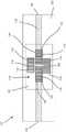
参考图1A,示出了串联压力换能器100的顶视图。类似地,图1B示出了压力换能器100的侧视图,并且图1C示出了在箭头A-A处截取的压力换能器100的剖视图。压力换能器100包括主体102、流体入口104、流体出口106以及在流体入口104和流体出口106之间延伸的流体腔108。流体腔108由主体102包封。虽然所示的实施方案包括流体入口104和流体出口106两者,但设想的其他实施方案包括单端换能器,该单端换能器包括充当流体入口和流体出口两者的单个流体入口。在该实施方案中,单个流体入口可被认为是流体接口端口。Referring to Figure 1A, a top view of a
应变仪110设置在位于主体102外部的表面112上。表面112可以是如图所示的平坦表面。在其他实施方案中,表面112可包括其上的一个或多个弯曲部。应变仪110包括惠斯通电桥,该惠斯通电桥具有位于表面112上的流体腔108的正上方的第一有效栅格114和第二有效栅格116,以及设置在表面112上的流体腔108的上方的第一平衡栅格118和设置在表面112上的流体腔108的下方的第二平衡栅格120。The strain gauges 110 are disposed on a
有效栅格114、116和平衡栅格118、120可各自包括图案化到直接附接到表面112的薄载体背衬124上的一个或多个电阻元件122或电阻器。薄载体背衬124可包括粘合剂层,该粘合剂层被配置为将栅格114、116、118、120附接到表面112。电阻元件122可各自为箔的薄金属线,该薄金属线具有随着电阻元件122上的应变而改变的特定电阻。电阻元件122可各自通过薄载体背衬124与主体102可操作地接触。本文的“可操作地接触”应意指其中由主体102经历的应变被传递到电阻元件122以改变电阻元件122的电阻的状态。换句话讲,尽管出于测量应变的目的,电阻元件122可操作地接触主体102,但薄载体背衬124可位于电阻元件122和主体102之间。
主体102可由具有第一热膨胀系数的材料制成。例如,主体102可由例如钛制成,并且可包括为或约为10.8 × 10⁻⁶的热膨胀系数。在其他实施方案中,主体102可由具有介于约17 × 10-6和18 × 10-6之间的热膨胀系数的钢或不锈钢制成。在其他实施方案中,主体102可由具有介于10 × 10-6至12 × 10-6之间的热膨胀系数的任何金属材料制成。主体102还可由热膨胀系数高达40 × 10-6(例如,对于锌而言)和低达2 × 10⁻⁶(例如,对于因瓦合金而言)的金属制成。The
电阻元件122可由具有与主体102的热膨胀系数不同的热膨胀系数的金属材料制成。例如,电阻元件122可由铝制成,其具有为或约为21 × 10-6的热膨胀系数。在其他实施方案中,电阻元件122可由康铜和镍铬铝铁合金制成,镍铬铝铁合金允许包括例如具有在13× 10-6至14 × 10-6之间的热膨胀系数的镍-铬。在其他实施方案中,电阻元件122可由钢或不锈钢制成,其具有介于约17 × 10-6至18 × 10-6之间的热膨胀系数。无论实施方案如何,电阻元件122可包括与主体102不同的热膨胀系数。换句话讲,电阻元件122可具有相对于主体102的失配的热膨胀系数。The
在示例性实施方案中,主体102可由具有10.8 × 10⁻⁶的热膨胀系数的钛制成,而电阻元件122可与具有介于17 × 10-6和18 × 10-6之间的热膨胀系数的不锈钢或钢匹配。在该示例性实施方案中,电阻元件122的热膨胀系数可高于主体102的热膨胀系数。然而,设想了其他实施方案,其中电阻元件122的热膨胀系数可低于主体102的热膨胀系数。设想了其他示例,诸如主体102和电阻元件122两者由不同的钢制成。在其他实施方案中,主体102可由钢制成,并且电阻元件可与铝匹配。In an exemplary embodiment, the
主体102和电阻元件122的热膨胀系数之间的失配水平可取决于在流体路径108或路径和应变仪110位于其上的表面112之间主体材料的厚度,或换句话讲,幅材厚度。在其中主体102由钛制成并且幅材厚度为.025英寸的情况下,主体102和电阻元件122的热膨胀系数之间的失配可以是大约10 × 10-6。换句话讲,电阻元件122可具有比主体102的热膨胀系数高10 × 10-6的热膨胀系数。已发现该量校正色谱溶剂的热诱导瞬态,例如在液相色谱系统中。各种其他程度的失配可以校正具有各种幅材厚度并经受各种形式的绝热热事件的压力换能器。The level of mismatch between the thermal expansion coefficients of the
在其他实施方案中,仅有效栅格114、116而不是平衡栅格118、120可具有相对于主体102的失配的热膨胀系数。在其他实施方案中,平衡栅格118、120而不是有效栅格114、116可包括相对于主体102的失配的热膨胀系数。在其他实施方案中,所有栅格114、116、118、120均包括相对于主体102的失配的系数热膨胀。在其他实施方案中,主体102可由具有第一热膨胀系数的第一材料制成,有效栅格114、116可由具有第二热膨胀系数的第二材料制成,并且平衡栅格118、120可由具有第三热膨胀系数的第三材料制成。In other embodiments, only the
栅格114、116、118、120的热膨胀系数可与主体102的热膨胀系数失配,使得热膨胀系数之间的差值可足够大,使得绝热热脉冲期间的输出电压变为正。在其他实施方案中,栅格114、116、118、120和主体102之间的热膨胀系数之间的差值可被配置为减少绝热热脉冲之后相对于第二压力换能器的稳定时间,该第二压力换能器具有与压力换能器100相同的性质,除了第二压力换能器在栅格和第二压力换能器的主体之间具有良好匹配的热膨胀系数之外。例如,栅格114、116、118、120和主体102之间的热膨胀系数之间的差值可被配置为相对于第二压力换能器将稳定时间减少至少50%。在其他实施方案中,与良好匹配的热膨胀系数相比,通过在栅格和主体之间使用失配的热膨胀系数,稳定时间可减少至少80%。这样,栅格114、116、118、120和主体102中的热膨胀系数的差值可被配置为补偿由例如下述因素引起的绝热脉冲:通过致动阀或从泵致动循环快速增大或减小压力,其中流体在液相色谱系统(诸如图11所示和下文所述的系统)中被快速压缩和解压缩。在其他实施方案中,设想了稳定时间可通过失配的热膨胀系数有意地增加,而不是有意地减少。The thermal expansion coefficients of the
流体腔108可被认为是被配置为接收加压流体的流体路径或其他流体主体。应变仪110可被配置为通过测量由主体102上的加压流体引起的应变来检测流体腔108或腔中的压力。表面112可以是从主体102移除的移除部分。在其他实施方案中,表面112可被模制或以其他方式整合到主体102中。如图1B和图1C所示,表面112被定位成比主体102的外圆周的其余部分更靠近流体腔108。The
在图1A至图1C所示的实施方案中,有效栅格114、116被定位成靠近流体腔108,而平衡栅格118、120被定位成相对于有效栅格114、116在流体腔108远侧。换句话讲,有效栅格114、116直接定位在流体腔108上面,而平衡栅格118、120分别定位在有效栅格114、116上方和下方。在其他实施方案中,如图2A至图2C所示,有效栅格和平衡栅格可被定位成彼此成直线。在该实施方案中,有效栅格和平衡栅格可相对于彼此正交地取向。In the embodiment shown in FIGS. 1A-1C , the
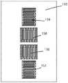
图2A至图2C示出了以设想的其他布置进行定位的有效栅格和平衡栅格的各种实施方案。这些实施方案所示的栅格可具有与其上放置栅格的主体失配的热膨胀系数,相似于上文关于图1A至图1C所述的实施方案。图2A至图2C示出了设想的实施方案不受栅格的任何特定位置或取向的限制。在图2A所示的实施方案中,表面130被示出为具有应变仪的第一有效栅格132、第二有效栅格134、第一平衡栅格136和第二平衡栅格138。有效栅格132、134和平衡栅格136、138可包括与图1A至图1C所示的有效栅格114、116和平衡栅格118、120相同的特征。然而,栅格132、134、136、138可以与栅格114、116、118、120不同的布置进行取向。应当理解,表面130可以是串联压力换能器的表面,诸如压力换能器100的表面112。然而,表面130可以是比表面112更长的表面,以便容纳应变仪的串联栅格114、116、118、120。在图2A所示的实施方案中,两个有效栅格132、134可串联地位于两个平衡栅格136、138之间。如图所示,有效栅格132、134可具有与水平延伸的导线长度和竖直延伸的连接弯曲部的栅格对准,而平衡栅格136、138可具有与竖直延伸的导线长度和水平延伸的连接弯曲部的栅格对准。这样,有效栅格132、134和平衡栅格136、138可相对于彼此正交地取向。Figures 2A-2C illustrate various embodiments of active and balanced grids positioned in other arrangements envisaged. The grids shown in these embodiments may have thermal expansion coefficients that are mismatched with the body on which the grid is placed, similar to the embodiments described above with respect to FIGS. 1A-1C . Figures 2A-2C illustrate that the contemplated embodiments are not limited by any particular position or orientation of the grid. In the embodiment shown in FIG. 2A, the
如图2B所示,表面140被示出为具有应变仪的第一有效栅格142、第二有效栅格144、第一平衡栅格146和第二平衡栅格148。有效栅格142、144、和平衡栅格146、148可包括与图1A至图1C所示的有效栅格114、116和平衡栅格118、120相同的特征。表面140可包括与图2A所示的表面130相同的特征。在图2B所示的实施方案中,第一有效栅格142可被放置在底部位置,接着是第一平衡栅格146,接下来是第二有效栅格144,并且最后是顶部上的第二平衡栅格148,所有这些栅格都是串联取向的。相似于图2A中的实施方案,有效栅格142、144可相对于平衡栅格146、148正交地取向。As shown in FIG. 2B,
如图2C所示,表面150被示出为具有应变仪的第一有效栅格152、第二有效栅格154、第一平衡栅格156和第二平衡栅格158。有效栅格152、154和平衡栅格156、158可包括与图1A至图1C所示的有效栅格114、116和平衡栅格118、120相同的特征。表面150可包括与图2A所示的表面130相同的特征。在图2C所示的实施方案中,第一有效栅格152可被放置在底部位置,接着是第一平衡栅格156,接下来是第二平衡栅格158,并且最后是顶部上的第二有效栅格154,所有这些栅格都是串联取向的。相似于图2A中的实施方案,有效栅格152、154可相对于平衡栅格156、158正交地取向。As shown in FIG. 2C,
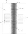
现在参考图3,示出了压力换能器100的表面112。在该图中,表面112上的变暗区域160表示由绝热事件引起的表面应变,该绝热事件诸如由热室或流体路径108内的压力的快速变化引起的绝热加热或冷却。因此,由于主体102受到来自绝热事件或热波的压缩,可将有效栅格114、116置于压缩状态。该压缩未冲击平衡栅格118、120。相反,由主体102牵拉至中心实际上可在位于平衡栅格118、120下面的主体102的位置处产生膨胀状态。随着热波向外扩展(未示出),波幅可消散并且收缩应变可径向地朝向表面112的左侧和右侧上的外边缘。随着热波耗散,栅格开始返回到其正常等温状态。在栅格114、116、118、120中的热膨胀系数高于主体102的情况下,当主体102由于绝热热事件而收缩时,栅格114、116、118、120将收缩得更多。由于栅格114、116、118、120粘结到主体102的表面112并且由此受到薄载体背衬124的约束,因此栅格114、116、118、120的收缩程度不能与它们处于自由非粘结状态时的收缩程度一样大。结果是尽管绝热事件的热波自然引起收缩,应变仪110所测量的实际应变也会增加。取决于失配的量,即使主体102经历导致绝热事件的收缩,甚至可能发生导致正输出电压的收缩热事件。在失配较小的情况下,应变仪110的输出电压可以为较小的负值和/或可以具有较小的峰值。Referring now to FIG. 3 , the
现在参考图4,示出了压力换能器100与除了在主体102与栅格114、116、118、120之间具有良好匹配的热膨胀系数之外具有与压力换能器100相同的性质的压力换能器相比的曲线图170,该压力换能器100的应变仪110在主体与栅格之间具有失配的热膨胀系数。曲线图170绘制了沿y轴的应变仪的压力输出对x轴上的稳定时间。具体地讲,在失配的压力换能器100的曲线172中,应变仪压力输出在仅两秒之后返回到零。相比之下,良好匹配的压力换能器的曲线174在十秒之后返回到零。在其中必须立即检测压力并且常见绝热热事件的行业和应用中,这种长的稳定时间可能是不可取的。Referring now to FIG. 4 , the
现在参考图5,示出了根据一个实施方案的压力换能器诸如压力换能器100的应变仪180的电气原理图。应变仪180可类似于应变仪110,并且可包括两个有效栅格181、182和两个平衡栅格183、184。然而,与应变仪110不同,应变仪180可包括附加的热电阻器185、186、187、188。栅格181、182、183、184不是相对于主体的热膨胀具有失配的热膨胀系数的电阻元件,而是附加的热电阻器185、186、187、188可以是相对于它们所附接的主体具有失配的热阻系数的电阻元件。在其他实施方案中,栅格181、182、183、184和附加热电阻器185、186、187、188均可包括相对于主体的失配的热阻系数。附加热电阻器185、186、187、188可以是低阻抗和/或低电阻电路元件。热电阻器185、186、187、188可各自串联连接到相应的有效栅格181、182和平衡栅格183、184,如图所示。在所示的实施方案中,靠近有效栅格181、182的热电阻器185、186可具有与靠近平衡栅格183、184的热电阻器187、188相同的热膨胀系数,但可具有不同的电阻。在其他实施方案中,热电阻器185、186、187、188中的每个热电阻器可具有相同的电阻和热阻系数。在其他实施方案中,热电阻器185、186、187、188中的每个热电阻器可具有相同的电阻和不同的热阻系数。在其他实施方案中,热电阻器185、186、187、188中的每个热电阻器可具有不同的电阻和不同的热阻系数。Referring now to FIG. 5, an electrical schematic of a pressure transducer, such as
参考图6,示出了根据一个实施方案的压力换能器诸如压力换能器100的应变仪190的电气原理图。应变仪190可类似于应变仪110,并且可包括两个有效栅格191、192和两个平衡栅格193、194。然而,与应变仪110不同但与应变仪180相似,应变仪190可包括附加的热电阻器195、196、197、198。栅格191、192、193、194不是相对于主体具有失配的热膨胀系数的电阻元件,而附加的热电阻器195、196、197、198可以是相对于它们所附接的主体具有失配的热阻系数的电阻元件。在其他实施方案中,栅格191、192、193、194和附加热电阻器195、196、197、198均可包括相对于主体的失配的热阻系数。附加热电阻器195、196、197、198可以是高阻抗和/或电阻电路元件,特别是与上文关于应变仪180所述的串联连接的热电阻器185、186、187、188相比。热电阻器195、196、197、198可各自并联连接到相应的有效栅格191、192和平衡栅格193、194,如图所示。在所示的实施方案中,与有效栅格191、192并联连接的热电阻器195、196可具有与并联连接到平衡栅格193、194的热电阻器197、198相同的热阻系数,但可具有不同的电阻。在其他实施方案中,热电阻器195、196、197、198中的每个热电阻器可具有相同的电阻和不同的热膨胀系数。在其他实施方案中,热电阻器195、196、197、198中的每个热电阻器可具有相同的电阻和不同的热阻系数。在其他实施方案中,热电阻器195、196、197、198中的每个热电阻器可具有不同的电阻和不同的热阻系数。Referring to FIG. 6, an electrical schematic of a pressure transducer, such as
虽然附图中描绘的实施方案仅包括串联压力换能器,但是设想了将相对于主体的应变仪上的失配电阻元件用于其他类型的压力换能器(包括例如膜片式压力换能器)的其他实施方案。While the embodiments depicted in the figures include only series pressure transducers, it is contemplated that mismatched resistive elements on the strain gauges relative to the body are used for other types of pressure transducers (including, for example, diaphragm pressure transducers) device) other implementations.
还设想了检测压力的方法。例如,检测压力的方法可包括提供第一压力换能器,诸如具有主体(诸如主体102)和电阻元件(诸如附接到主体的电阻元件122中的一个或多个电阻元件122)的第一压力换能器100。该方法可包括使主体的第一热膨胀系数与电阻元件的第二热膨胀系数失配。该方法可包括利用第一压力换能器检测流体系统的压力。该方法可包括在绝热热脉冲期间利用压力换能器检测压力。该方法还可包括相对于第二压力换能器将绝热热脉冲后的稳定时间减少至少50%,该第二压力换能器具有与第一压力换能器相同的性质,除了第二压力换能器具有良好匹配的热膨胀系数之外。第二热膨胀系数可大于第一热膨胀系数。该方法还可包括在绝热热脉冲期间输出正输出电压。该方法可包括利用失配的第一系数热膨胀和第二系数热膨胀来补偿绝热热脉冲。Methods of detecting pressure are also contemplated. For example, a method of detecting pressure may include providing a first pressure transducer, such as a first having a body (such as body 102 ) and a resistive element (such as one or more of
现在参考图7A,示出了根据一个实施方案的串联压力换能器200的顶视图。类似地,图7B示出了压力换能器200的侧视图,并且图7C示出了在箭头B-B处截取的压力换能器200的剖视图。压力换能器200包括主体202、流体入口204、流体出口206以及在流体入口204和流体出口206之间延伸的流体腔208。流体入口204和流体出口206可以包括内螺纹(未示出),该内螺纹被配置为接收连接器、端口、配件或其他联接件,以用于将串联压力换能器200连接到流体系统,诸如液相色谱系统。虽然所示的实施方案包括流体入口204和流体出口206两者,但设想的其他实施方案包括单端换能器,该单端换能器包括充当流体入口和流体出口两者的单个流体入口。在该实施方案中,单个流体入口可被认为是流体接口端口。Referring now to FIG. 7A, a top view of a
流体腔208由主体202包封。应变仪210设置在位于主体202外侧上的表面212上。表面212可以是如图所示的平坦表面。在其他实施方案中,表面212可包括其上的一个或多个弯曲部。应变仪210包括惠斯通电桥,该惠斯通电桥具有位于表面212上的流体腔208的正上方的第一有效栅格214和第二有效栅格216,以及设置在表面212上的流体腔208的上方的第一平衡栅格218和设置在表面212上的流体腔208的下方的第二平衡栅格220。所示的有效栅格214、216和平衡栅格218、220的取向和位置是示例性的,并且设想了各种其他取向。
流体腔208可被认为是被配置为接收加压流体的流体路径或其他流体主体。应变仪210可被配置为通过测量由主体202上的加压流体引起的应变来检测流体腔208或腔中的压力。表面212可以是从主体202移除的移除部分。在其他实施方案中,表面212可被模制或以其他方式整合到主体202中。如图2B和图2C所示,表面212被定位成比主体202的外圆周的其余部分更靠近流体腔208。
在流体腔208内示出了填料主体230。填料主体230可延伸流体腔208的相当大的长度,如图7A和图7B所示。填料主体230可延伸流体腔208的几乎整个长度。在其他实施方案中,填料主体320可仅位于应变仪210和/或表面212的正下方的位置处。The packing
填料主体230可以位于流体腔或流体腔208内,并且可以被配置为减小对压力换能器200的主体202的绝热热效应。填料主体230可以减小流体腔208内的体积。如图7C所示,填料主体230还可被配置为将流体腔或流体腔208的横截面积减小到减小的横截面积232。在流体入口204和流体出口206已成直线连接到如上文所述的流体系统之后,减小的横截面积232可以是比在流体入口204和/或流体出口206处的最小横截面积更大或更巨大的面积。在其他实施方案中,在流体入口204和流体出口206已成直线连接到如上文所述的流体系统之后,减小的横截面积232可以是与在流体入口204和/或流体出口206处的最小横截面积相等的横截面积。无论实施方案如何,减小的横截面积232可以不是用于减小通过流体系统的流体流的体积的限制尺寸。The
在一个实施方案中,填料主体230可包含与压力换能器200的主体202相同的材料。在其他实施方案中,填料主体230可由与主体202的材料不同的材料制成。填料主体230和主体202可由金属材料,诸如,例如锌、不锈钢、钛、因瓦合金或铝制成。在其他实施方案中,主体202可以是金属材料,但填料主体230可由非金属材料诸如塑料、复合材料或合成材料制成。填料主体230可以是在压力换能器200的制造期间设置在流体腔208内的与流体腔208的形状分开的部件。将填料主体230设置在流体腔208内可包括将填料主体焊接或以其他方式附接到流体腔208中。在其他实施方案中,填料主体230可简单地为流体腔208的整体形状。In one embodiment, the
如图7C所示,填料主体230可具有圆柱形形状。填料主体230的圆柱形主体或形状可具有比流体腔208的直径更小的直径。填料主体230被示为位于流体腔或流体腔208内的在应变仪210远侧的位置处。具体地讲,填料主体230位于流体腔208的底部。因此,填料主体230可不接触位于应变仪210正下方的流体腔208的内表面的感测区域231。感测区域可包括流体腔208的内表面的上半部。这可以允许流体紧密地流动到幅材厚度,使得压力换能器200可以更容易地检测流体腔208内的压力。填料主体230可以是如图所示的实心圆柱体。流体路径空间232位于填料主体230上方,在填料主体230与流体腔208的圆周之间。As shown in Figure 7C, the
尽管图7A至图7C的填料主体230是位于流体腔208内的实心圆柱体,但设想了其他成形填料主体,如图8A至图8F所示。尽管在图8A至图8F中示出了若干形状,但本发明并不限于这些形状。Although the
图8A描绘了在沿其长度的中点处的串联压力换能器240的剖视图。压力换能器240包括应变仪242和流体腔或路径244。压力换能器还包括设置在流体腔或路径244内的填料主体246,该填料主体246被配置为在任何给定时间减小存在于流体腔或路径244内的流体体积。第一流体路径空间248可位于填料主体246外侧,并且第二流体路径空间249可位于填料主体246之内。在该实施方案中,填料主体246可具有中空圆柱形状。换句话讲,填料主体246可以是具有比流体腔或路径244的直径更小的直径的管状主体,并且可位于流体腔或路径244的中间。填料主体246可以松散或未附接的方式设置在流体腔或路径244内。在其他实施方案中,填料主体246可用延伸部分(未示出)附接到流体腔或路径244,该延伸部分在填料主体246和流体腔244之间延伸并将填料主体246保持在所示位置中。8A depicts a cross-sectional view of the
图8B示出了在沿其长度的中点处的串联压力换能器250的剖视图。压力换能器250包括应变仪252和流体腔或路径254。压力换能器还包括设置在流体腔或路径254内的填料主体256,该填料主体256被配置为在任何给定时间减小存在于流体腔或路径254内的流体体积。流体路径空间258可位于填料主体246外侧。在该实施方案中,填料主体256可具有大于上文所述的填料主体230的实心圆柱形形状。填料主体256可以与填料主体230类似的方式设置在流体腔或路径256内,在流体腔或路径254的底部处。Figure 8B shows a cross-sectional view of the
图8C描绘了在沿其长度的中点处的串联压力换能器260的剖视图。压力换能器260包括应变仪262和流体腔或路径264。压力换能器还包括设置在流体腔或路径264内的填料主体266,该填料主体266被配置为在任何给定时间减小存在于流体腔或路径264内的流体体积。流体路径空间268可位于填料主体266上方。当填料主体266附接到流体腔264时,填料主体266可具有圆柱形形状,其中平坦的移除部分沿圆柱形的长度设置在靠近应变仪262的周向位置处。填料主体266可附接到流体腔或路径264。除了移除的部分之外,填料主体266可具有与流体腔或路径264的圆周基本上类似的外圆周。8C depicts a cross-sectional view of the
图8D描绘了在沿其长度的中点处的串联压力换能器270的剖视图。压力换能器270包括应变仪272和流体腔或路径274。压力换能器还包括设置在流体腔或路径274内的填料主体276,该填料主体276被配置为在任何给定时间减小存在于流体腔或路径274内的流体体积。第一流体路径空间278可位于填料主体276上方,并且第二流体路径空间279可位于填料主体276下方。在该实施方案中,填料主体276可以是平条,该平条延伸跨过具有弯曲边缘的流体腔或路径274的横截面积。弯曲边缘可在尺寸上对应于流体腔或路径274的圆周。填料主体276可在弯曲边缘处附接到流体腔或路径274。8D depicts a cross-sectional view of the
图8E描绘了在沿其长度的中点处的串联压力换能器280的剖视图。压力换能器280包括应变仪282和流体腔或路径284。压力换能器还包括设置在流体腔或路径284内的填料主体286,该填料主体286被配置为在任何给定时间减小存在于流体腔或路径284内的流体体积。填料主体286可以是“X”形的,并且可在X的延伸部处附接到流体腔或路径284。第一流体路径空间285可位于填料主体286上方,第二流体路径空间287可位于填料主体286的右侧,第三流体路径空间288可位于填料主体286下方,并且第四流体路径空间289可位于填料主体286的左侧。8E depicts a cross-sectional view of the
图8F描绘了在沿其长度的中点处的串联压力换能器290的剖视图。压力换能器290包括应变仪292和流体腔或路径294。压力换能器还包括设置在流体腔或路径294内的填料主体296,该填料主体296被配置为在任何给定时间减小存在于流体腔或路径294内的流体体积。填料主体296可具有带有倒圆或倒角外边缘的正方形横截面,并且可在倒圆外边缘处附接到流体腔或路径294。第一流体路径空间295可位于填料主体296上方,第二流体路径空间297可位于填料主体296的右侧,第三流体路径空间298可位于填料主体296下方,并且第四流体路径空间299可位于填料主体296的左侧。8F depicts a cross-sectional view of the
图9A描绘了根据一个实施方案的膜片压力换能器300的顶视图,而图9B描绘了在箭头C-C处截取的图8A的压力换能器的剖面图。膜片压力换能器300包括主体302、流体入口304、流体出口306,以及位于流体入口304和流体出口306之间并由主体202包封的流体腔308。尽管所示的实施方案包括流体入口304和流体出口306两者,但设想的其他实施方案包括单端换能器,该单端换能器包括充当流体入口和流体出口两者的单个流体入口。在该实施方案中,单个流体入口可被认为是流体接口端口。9A depicts a top view of a
应变仪310设置在位于膜片压力换能器300的主体302的外侧上的膜片表面312上。应变仪310包括具有如上文所述的栅格的惠斯通电桥。应变仪310可被配置为通过测量由主体302或膜片表面312上的加压流体引起的应变来检测流体腔308中的压力。膜片表面312可以是位于流体腔308上方的表面。The strain gauges 310 are disposed on the
在流体腔308内示出了填料主体330。相似于上文所述的填料主体,填料主体330可以位于流体腔308内,并且可以被配置为减小压力换能器300的主体302上的绝热热效应。填料主体330可减小流体腔308内的体积。如图9B所示,填料主体330还可被配置为减小流体腔308的横截面积。腔308的减小的横截面积可以是比流体入口304和/或流体出口306处的最小横截面积更大或更巨大的面积。在其他实施方案中,减小的横截面积可以是与流体入口304和/或流体出口306处的最小横截面积相等的横截面积。无论实施方案如何,减小的横截面积可以不是用于减小通过流体系统的流体流的体积的限制尺寸。The packing
膜片压力换能器300的填料主体330和主体302可以由与上文关于串联压力换能器200的填料主体230和主体202所述的那些材料相同的材料制成。在产生或制造膜片压力换能器300时,主体302的下部主体部分314和主体302的上部主体部分316可在填料主体330已被设置、附接或以其他方式包括在腔308中之后接合、焊接或以其他方式附接。在其他实施方案中,填料主体330可简单地为流体腔308的整体形状。The packing
图10描绘了压力换能器200与除了不具有与流体腔或路径一起定位的填料主体之外具有与压力换能器200相同的性质的压力换能器相比的曲线图400,该压力换能器200被示出具有设置或以其他方式包括在流体腔或路径208中的填料主体230。曲线图400绘制了沿y轴的应变仪的压力输出对x轴上的稳定时间。具体地讲,曲线412示出了包括填料主体230的压力换能器200,应变仪压力输出在仅0.15秒之后返回到零。相比之下,没有填料主体的压力换能器的曲线410在一整秒之后返回到零。在其中必须立即检测压力并且常见绝热热事件的行业和应用中,这种长的响应时间可能是不可取的。FIG. 10 depicts a
还设想了制造压力换能器和/或检测压力的其他方法。在一个实施方案中,一种方法包括提供压力换能器,诸如压力换能器200、300中的一个压力换能器,其具有流体入口,诸如流体入口204、304中的一个流体入口,流体出口,诸如流体出口206、306中的一个流体出口,以及位于由换能器主体包封的流体入口和流体出口之间的流体腔,诸如流体腔208、308中的一个流体腔。该方法可包括将应变仪附接到换能器主体,诸如应变仪210、310中的一个应变仪。该方法可包括将填料主体整合在流体腔内,诸如填料主体230、246、256、266、276、286、296、330中的一个填料主体。该方法可包括利用填料主体减小流体腔的体积。此外,该方法可包括相对于第二压力换能器利用填料主体来减小换能器主体上的绝热热效应,该第二压力换能器具有与压力换能器相同的性质,除了第二压力换能器被制造成没有填料主体之外。该方法还可包括沿具有填料主体的腔的长度将腔横截面积减小到减小的横截面积。减小的横截面积可大于或等于流体入口处的入口横截面积。该方法可包括使流体腔的内表面的感测区域不与填料主体接触,该感测区域诸如感测区域231位于填料腔内的应变仪的正下方。Other methods of making pressure transducers and/or detecting pressure are also contemplated. In one embodiment, a method includes providing a pressure transducer, such as one of
图11描绘了根据一个实施方案的液相色谱系统500的示意图。液相色谱系统500可包括各种特征,诸如溶剂或流动相贮存器510、泵、溶剂管理器或其他溶剂递送系统520、具有样品注射器或样品管理器540的样品容器530、液相色谱柱550、检测器560、废物贮存器或系统570以及控制或计算机系统或其他色谱图580。液相色谱系统500可以是流体系统,该流体系统被配置为向分离柱550提供包含溶剂510和样品530两者的混合液体以用于由检测器进行分离和分析。液相色谱系统500可以是高效液相色谱系统、气相色谱系统等。本文所述的压力换能器中的一个或多个压力换能器可包括在液相色谱系统500中以检测流体压力和/或提供系统控制和/或系统反馈。在一个实施方案中,本文所述的压力换能器中的一个或多个压力换能器可在泵、溶剂管理器或溶剂递送系统520之前、之后和/或之内包括在液相色谱系统500中。还设想了系统中的其他位置。此外,除了液相色谱系统之外,其他流体系统可结合与本文所述实施方案一致的压力换能器。FIG. 11 depicts a schematic diagram of a
虽然已经参考特定实施方案示出和描述了本发明,但是本领域的技术人员应理解,在不脱离如所附权利要求中叙述的本发明的实质和范围的情况下,可以在形式和细节上进行各种改变。例如,微量吸移管的各种实施方案被描述为分配三个或四个等分试样,应当认识到,在其他实施方案中,微量吸移管可被配置为从单个样品收集中递送其他数量的等分试样。Although the present invention has been shown and described with reference to specific embodiments, it will be understood by those skilled in the art that changes may be made in form and detail without departing from the spirit and scope of the invention as recited in the appended claims Make various changes. For example, while various embodiments of micropipettes are described as dispensing three or four aliquots, it will be appreciated that in other embodiments, micropipettes may be configured to deliver other quantities from a single sample collection Aliquots.
Claims (18)
Translated fromChinesePriority Applications (1)
| Application Number | Priority Date | Filing Date | Title |
|---|---|---|---|
| CN202211150331.4ACN115452241A (en) | 2018-05-24 | 2019-05-23 | Pressure transducers, systems and methods |
Applications Claiming Priority (3)
| Application Number | Priority Date | Filing Date | Title |
|---|---|---|---|
| US201862675849P | 2018-05-24 | 2018-05-24 | |
| US62/675849 | 2018-05-24 | ||
| PCT/US2019/033753WO2019226895A1 (en) | 2018-05-24 | 2019-05-23 | Pressure transducer, system and method |
Related Child Applications (1)
| Application Number | Title | Priority Date | Filing Date |
|---|---|---|---|
| CN202211150331.4ADivisionCN115452241A (en) | 2018-05-24 | 2019-05-23 | Pressure transducers, systems and methods |
Publications (2)
| Publication Number | Publication Date |
|---|---|
| CN112204366A CN112204366A (en) | 2021-01-08 |
| CN112204366Btrue CN112204366B (en) | 2022-09-20 |
Family
ID=66998476
Family Applications (2)
| Application Number | Title | Priority Date | Filing Date |
|---|---|---|---|
| CN201980034965.3AActiveCN112204366B (en) | 2018-05-24 | 2019-05-23 | Pressure transducers, systems and methods |
| CN202211150331.4APendingCN115452241A (en) | 2018-05-24 | 2019-05-23 | Pressure transducers, systems and methods |
Family Applications After (1)
| Application Number | Title | Priority Date | Filing Date |
|---|---|---|---|
| CN202211150331.4APendingCN115452241A (en) | 2018-05-24 | 2019-05-23 | Pressure transducers, systems and methods |
Country Status (4)
| Country | Link |
|---|---|
| US (2) | US11204293B2 (en) |
| EP (2) | EP4560281A3 (en) |
| CN (2) | CN112204366B (en) |
| WO (1) | WO2019226895A1 (en) |
Families Citing this family (3)
| Publication number | Priority date | Publication date | Assignee | Title |
|---|---|---|---|---|
| CN112204366B (en)* | 2018-05-24 | 2022-09-20 | 沃特世科技公司 | Pressure transducers, systems and methods |
| US11156511B2 (en)* | 2019-04-09 | 2021-10-26 | Honeywell International Inc. | Load cell |
| DE102020112982A1 (en)* | 2020-05-13 | 2021-11-18 | Voss Fluid Gmbh | Connection piece for fluid-carrying line systems |
Family Cites Families (15)
| Publication number | Priority date | Publication date | Assignee | Title |
|---|---|---|---|---|
| US4574640A (en)* | 1984-11-29 | 1986-03-11 | Bourns Instruments, Inc. | Integrated dual-range pressure transducer |
| DE8610711U1 (en)* | 1986-04-18 | 1986-11-13 | Haenni & Cie Mbh, 7000 Stuttgart | Pipe pressure seal |
| US4726232A (en)* | 1986-06-02 | 1988-02-23 | Gould Inc. | Temperature coefficient compensated pressure transducer |
| US4994781A (en)* | 1988-04-07 | 1991-02-19 | Sahagen Armen N | Pressure sensing transducer employing piezoresistive elements on sapphire |
| CN1024842C (en)* | 1989-08-25 | 1994-06-01 | 株式会社长野计器制作所 | Strain detection element and pressure transducer using the same |
| JP4337656B2 (en) | 2004-06-29 | 2009-09-30 | 株式会社デンソー | Pressure sensor |
| US6928878B1 (en)* | 2004-09-28 | 2005-08-16 | Rosemount Aerospace Inc. | Pressure sensor |
| DE102008055123B3 (en)* | 2008-12-23 | 2010-07-22 | Robert Bosch Gmbh | Ultrasonic transducer for use in a fluid medium |
| US7775119B1 (en)* | 2009-03-03 | 2010-08-17 | S3C, Inc. | Media-compatible electrically isolated pressure sensor for high temperature applications |
| US9304115B2 (en) | 2010-05-10 | 2016-04-05 | Waters Technologies Corporation | Pressure sensing and flow control in diffusion-bonded planar devices for fluid chromatography |
| JP5454628B2 (en) | 2012-06-29 | 2014-03-26 | 株式会社デンソー | Pressure sensor |
| WO2014188817A1 (en) | 2013-05-24 | 2014-11-27 | 日立金属株式会社 | Pressure sensor, and mass flow meter and mass flow controller using same |
| GB2542650B (en)* | 2015-06-10 | 2018-05-30 | Waters Technologies Corp | Sensor body for a flow through pressure sensor |
| US10620071B2 (en)* | 2016-06-29 | 2020-04-14 | Danfoss A/S | Pressure sensor and method for manufacturing a pressure sensor |
| CN112204366B (en)* | 2018-05-24 | 2022-09-20 | 沃特世科技公司 | Pressure transducers, systems and methods |
- 2019
- 2019-05-23CNCN201980034965.3Apatent/CN112204366B/enactiveActive
- 2019-05-23EPEP25169503.7Apatent/EP4560281A3/enactivePending
- 2019-05-23EPEP19732157.3Apatent/EP3803308B1/enactiveActive
- 2019-05-23USUS16/420,845patent/US11204293B2/enactiveActive
- 2019-05-23CNCN202211150331.4Apatent/CN115452241A/enactivePending
- 2019-05-23WOPCT/US2019/033753patent/WO2019226895A1/ennot_activeCeased
- 2021
- 2021-11-09USUS17/521,986patent/US11927498B2/enactiveActive
Also Published As
| Publication number | Publication date |
|---|---|
| US20220065721A1 (en) | 2022-03-03 |
| US11927498B2 (en) | 2024-03-12 |
| US11204293B2 (en) | 2021-12-21 |
| EP3803308A1 (en) | 2021-04-14 |
| EP3803308B1 (en) | 2025-05-21 |
| US20190360883A1 (en) | 2019-11-28 |
| EP4560281A3 (en) | 2025-08-20 |
| CN112204366A (en) | 2021-01-08 |
| EP4560281A2 (en) | 2025-05-28 |
| CN115452241A (en) | 2022-12-09 |
| WO2019226895A1 (en) | 2019-11-28 |
Similar Documents
| Publication | Publication Date | Title |
|---|---|---|
| US11927498B2 (en) | Adiabatic reducing pressure transducer, system and method | |
| US5750899A (en) | Capacitive pressure sensor with sensing element mechanically isolated from the casing | |
| JP5153126B2 (en) | Sensor device for measuring fluid pressure and temperature | |
| JP3431923B2 (en) | Coriolis flow meter with axially flexible case end | |
| US7373830B2 (en) | Metal/thermo plastic port design for media isolated pressure transducers | |
| CN207556734U (en) | Pressure sensor assembly | |
| US11499881B2 (en) | Variable thickness diaphragm pressure transducer and method | |
| CN106248290B (en) | Sensor body for a flow-through pressure sensor | |
| US7921724B2 (en) | Apparatus and method for eliminating varying pressure fluctuations in a pressure transducer | |
| CN107782485B (en) | Differential pressure sensor integrated with common mode error compensation | |
| KR101209762B1 (en) | Flow sensor and mass flow control device using it | |
| US7559246B2 (en) | Sensor for measuring low dynamic pressures in the presence of high static pressures | |
| US8739632B2 (en) | Pressure sensor structure and associated method of making a pressure sensor | |
| US7360430B2 (en) | High impedance thin film for strain gauge applications | |
| US4306460A (en) | Differential pressure transducer | |
| Bannikoppa et al. | Design of piezoresistive pressure sensor for enhanced sensitivity | |
| JP2007101544A (en) | Method for detecting pressure of medium, and pressure measurement device | |
| CN212254177U (en) | Pipeline graphene composite film sensor | |
| US20230221202A1 (en) | Pressure sensor formed by strain gauge on a deformable membrane of a fluid device | |
| JP2013148468A (en) | Pressure measuring device |
Legal Events
| Date | Code | Title | Description |
|---|---|---|---|
| PB01 | Publication | ||
| PB01 | Publication | ||
| SE01 | Entry into force of request for substantive examination | ||
| SE01 | Entry into force of request for substantive examination | ||
| GR01 | Patent grant | ||
| GR01 | Patent grant |