CN112180075B - Automatic medical urine sample collecting equipment - Google Patents
Automatic medical urine sample collecting equipmentDownload PDFInfo
- Publication number
- CN112180075B CN112180075BCN202011013331.0ACN202011013331ACN112180075BCN 112180075 BCN112180075 BCN 112180075BCN 202011013331 ACN202011013331 ACN 202011013331ACN 112180075 BCN112180075 BCN 112180075B
- Authority
- CN
- China
- Prior art keywords
- liquid storage
- collection chamber
- output end
- arc
- sample collection
- Prior art date
- Legal status (The legal status is an assumption and is not a legal conclusion. Google has not performed a legal analysis and makes no representation as to the accuracy of the status listed.)
- Active
Links
Images


Classifications
- G—PHYSICS
- G01—MEASURING; TESTING
- G01N—INVESTIGATING OR ANALYSING MATERIALS BY DETERMINING THEIR CHEMICAL OR PHYSICAL PROPERTIES
- G01N33/00—Investigating or analysing materials by specific methods not covered by groups G01N1/00 - G01N31/00
- G01N33/48—Biological material, e.g. blood, urine; Haemocytometers
- G01N33/483—Physical analysis of biological material
- G01N33/487—Physical analysis of biological material of liquid biological material
- G01N33/493—Physical analysis of biological material of liquid biological material urine
- G—PHYSICS
- G01—MEASURING; TESTING
- G01N—INVESTIGATING OR ANALYSING MATERIALS BY DETERMINING THEIR CHEMICAL OR PHYSICAL PROPERTIES
- G01N35/00—Automatic analysis not limited to methods or materials provided for in any single one of groups G01N1/00 - G01N33/00; Handling materials therefor
- G01N35/10—Devices for transferring samples or any liquids to, in, or from, the analysis apparatus, e.g. suction devices, injection devices
- G01N35/1009—Characterised by arrangements for controlling the aspiration or dispense of liquids
- Y—GENERAL TAGGING OF NEW TECHNOLOGICAL DEVELOPMENTS; GENERAL TAGGING OF CROSS-SECTIONAL TECHNOLOGIES SPANNING OVER SEVERAL SECTIONS OF THE IPC; TECHNICAL SUBJECTS COVERED BY FORMER USPC CROSS-REFERENCE ART COLLECTIONS [XRACs] AND DIGESTS
- Y02—TECHNOLOGIES OR APPLICATIONS FOR MITIGATION OR ADAPTATION AGAINST CLIMATE CHANGE
- Y02W—CLIMATE CHANGE MITIGATION TECHNOLOGIES RELATED TO WASTEWATER TREATMENT OR WASTE MANAGEMENT
- Y02W30/00—Technologies for solid waste management
- Y02W30/10—Waste collection, transportation, transfer or storage, e.g. segregated refuse collecting, electric or hybrid propulsion
Landscapes
- Health & Medical Sciences (AREA)
- Life Sciences & Earth Sciences (AREA)
- Engineering & Computer Science (AREA)
- Chemical & Material Sciences (AREA)
- Biomedical Technology (AREA)
- Physics & Mathematics (AREA)
- General Physics & Mathematics (AREA)
- Immunology (AREA)
- Pathology (AREA)
- Urology & Nephrology (AREA)
- General Health & Medical Sciences (AREA)
- Biochemistry (AREA)
- Analytical Chemistry (AREA)
- Medicinal Chemistry (AREA)
- Food Science & Technology (AREA)
- Biophysics (AREA)
- Hematology (AREA)
- Molecular Biology (AREA)
- Investigating Or Analysing Biological Materials (AREA)
- Sampling And Sample Adjustment (AREA)
Abstract
Description
Translated fromChinese技术领域technical field
本发明属于医疗设备技术领域,特别是涉及一种医疗用尿液样本自动化采集设备。The invention belongs to the technical field of medical equipment, in particular to an automatic medical urine sample collection equipment.
背景技术Background technique
尿液物理化学分析作为一种常见医学检查项目,在实际医疗活动中经常要求病人留取尿液进行检测。尿液检查对泌尿系统疾病来说,是一项重要的诊断依据。留尿时最好留取中段尿。按排尿的先后次序,可将尿液分为前段、中段、后段。因前段尿和后段尿容易被污染,因此,做尿常规和尿细菌学检查时,一般都留取中段尿。目前通常采用的方法是使用尿杯采集尿液,但是这种方法很容易将尿液撒到手上或其他部位,同时,由于尿杯没有杯盖,一不小心尿液就会撒漏,尿液的气味也会散发,对其他就医人员造成不便,而且不容易采集到中段尿,也很难控制采集量。另一方面,在尿液取样时,没有经验的用户会对采集的过程感到尴尬,用户体验较差。Urine physicochemical analysis is a common medical examination item, and patients are often required to retain urine for testing in actual medical activities. Urine examination is an important diagnostic basis for urinary system diseases. When urinating, it is best to keep the middle urine. According to the sequence of urination, the urine can be divided into front, middle and back. Because the front-segment urine and the back-segment urine are easily contaminated, the middle-segment urine is generally retained when doing urine routine and urine bacteriological examination. At present, the commonly used method is to use a urine cup to collect urine, but this method is easy to scatter the urine on the hands or other parts. The smell of the urine will also be distributed, causing inconvenience to other medical personnel, and it is not easy to collect the middle urine, and it is also difficult to control the collection amount. On the other hand, when taking urine samples, inexperienced users will feel embarrassed about the collection process, and the user experience is poor.
发明内容Contents of the invention
本发明的目的之一在于提供一种医疗用尿液样本自动化采集设备,通过利用第二驱动机构进行取样工作,利用传送机构、弧形储液管进行储液工作,实现了对尿液样本的自动化采集,减少了用户的直接接触,使得尿液取样过程更加人性化、卫生化。One of the objects of the present invention is to provide a medical urine sample automatic collection device, by using the second driving mechanism to carry out the sampling work, using the transmission mechanism and the arc-shaped liquid storage tube to carry out the liquid storage work, the urine sample is realized. Automatic collection reduces the direct contact of users and makes the urine sampling process more humanized and hygienic.
本发明的目的之一在于提供一种医疗用尿液样本自动化采集设备,弧形储液管的设置,提高了对用户中段尿液的取样精度,第三矩形板的设置,减少了多余尿液对取样管或本发明设备的污染。One of the objectives of the present invention is to provide an automatic medical urine sample collection device. The arrangement of the arc-shaped liquid storage tube improves the sampling accuracy of the user's mid-section urine, and the arrangement of the third rectangular plate reduces excess urine. Contamination of the sampling line or the device of the invention.
本发明的目的之一在于提供一种医疗用尿液样本自动化采集设备,两第二夹持块与第一弹簧的配合,既实现了对取样管的夹持,也便于用户取走取样管。One of the objectives of the present invention is to provide an automatic urine sample collection device for medical use. The cooperation between the two second clamping blocks and the first spring not only realizes the clamping of the sampling tube, but also facilitates the user to remove the sampling tube.
为解决上述技术问题,本发明是通过以下技术方案实现的,当然,实施本发明的任一产品并不一定需要同时达到以上所述的所有优点:In order to solve the problems of the technologies described above, the present invention is achieved through the following technical solutions. Of course, implementing any product of the present invention does not necessarily need to reach all the advantages described above simultaneously:
一种医疗用尿液样本自动化采集设备,包括:壳体,壳体内设有储液管收集室、样本采集室,储液管收集室与样本采集室之间设有隔板,隔板上侧装设有传送机构,传送机构上装设有多个弧形储液管,弧形储液管的中部设有橡胶塞;An automatic urine sample collection device for medical use, comprising: a casing, a liquid storage tube collection chamber and a sample collection chamber are arranged in the casing, a partition is provided between the liquid storage tube collection chamber and the sample collection chamber, and the upper side of the partition is A transmission mechanism is installed, and a plurality of arc-shaped liquid storage tubes are installed on the transmission mechanism, and a rubber plug is provided in the middle of the arc-shaped liquid storage tubes;
样本采集室包括设于远离隔板一侧的侧板,侧板的宽度方向上开设有通孔、与储液管相对应的通道;样本采集室内装设有第二驱动机构,第二驱动机构的输出端装设有第一夹持组件,第一夹持组件的上部装设有取样管,取样管内设有螺纹柱。The sample collection chamber includes a side plate located on the side away from the partition, and a through hole and a channel corresponding to the liquid storage tube are opened on the width direction of the side plate; a second drive mechanism is installed in the sample collection chamber, and the second drive mechanism A first clamping assembly is installed at the output end of the first clamping assembly, a sampling tube is installed on the upper part of the first clamping assembly, and a threaded column is arranged inside the sampling tube.
可选的,第二驱动机构包括x、y轴平移组件,x、y轴平移组件的输出端装设有第一电动推杆,第一电动推杆的输出端装设有第二矩形板,第二矩形板的输出端装设有旋转电机,第一夹持组件装设于旋转电机的输出端。Optionally, the second drive mechanism includes an x, y axis translation assembly, the output end of the x, y axis translation assembly is equipped with a first electric push rod, and the output end of the first electric push rod is equipped with a second rectangular plate, A rotating motor is installed on the output end of the second rectangular plate, and the first clamping assembly is installed on the output end of the rotating motor.
可选的,第一夹持组件包括装设于旋转电机输出端的两第二夹持块,且两第二夹持块之间装设有第一弹簧,取样管底部装设有两凸块。Optionally, the first clamping assembly includes two second clamping blocks installed at the output end of the rotating motor, and a first spring is installed between the two second clamping blocks, and two protrusions are installed at the bottom of the sampling tube.
可选的,x、y轴平移组件包括装设于样本采集室内壁横向方向的第一电动导轨,第一电动导轨的输出端装设有第二电动导轨,且第一电动导轨与第二电动导轨位置上垂直,第一电动推杆装设于第二电动导轨的输出端。Optionally, the x and y-axis translation components include a first motorized guide rail installed in the lateral direction of the sample collection chamber wall, a second motorized guide rail is installed at the output end of the first motorized guide rail, and the first motorized guide rail and the second motorized guide rail The position of the guide rail is vertical, and the first electric push rod is installed at the output end of the second electric guide rail.
可选的,样本采集室内壁开设有储物槽,储物槽两侧分别设有滑道、槽道,滑道内放置有多个取样管,且滑道相对于水平面倾斜设置,储物槽的槽口处设有挡板。Optionally, a storage tank is provided on the inner wall of the sample collection chamber, slides and grooves are respectively provided on both sides of the storage tank, and a plurality of sampling tubes are placed in the slides, and the slides are arranged inclined relative to the horizontal plane. A baffle is provided at the notch.
可选的,传送机构包括输送机,输送机包括输送带,输送带上均布有第二夹持组件。Optionally, the transmission mechanism includes a conveyor, and the conveyor includes a conveyor belt, and the second clamping components are evenly distributed on the conveyor belt.
可选的,第二夹持组件包括设于输送带上的矩形块,矩形块上装设有第一矩形板,第一矩形板上装设有四个第一夹持块,且四个第一夹持块首尾依次通过第二弹簧连接,且四个第一夹持块之间形成一夹持空间。Optionally, the second clamping assembly includes a rectangular block arranged on the conveyor belt, a first rectangular plate is mounted on the rectangular block, four first clamping blocks are mounted on the first rectangular plate, and the four first clamping blocks The head and tail of the holding blocks are sequentially connected by the second spring, and a holding space is formed between the four first holding blocks.
可选的,弧形储液管中部设有出口管,且橡胶塞位于出口管内,且橡胶塞的底部设有与螺纹柱相配合的第一螺纹槽。Optionally, an outlet pipe is provided in the middle of the arc-shaped liquid storage pipe, and the rubber plug is located in the outlet pipe, and the bottom of the rubber plug is provided with a first threaded groove matching the threaded column.
可选的,取样管的上部设有盖板,且盖板一面设有与螺纹柱相配合的第二螺纹槽。Optionally, the upper part of the sampling tube is provided with a cover plate, and one side of the cover plate is provided with a second thread groove matched with the threaded column.
可选的,通孔靠近样本采集室的一端为缩口,通孔远离样本采集室的一端为扩口,通孔内放置有漏斗,且漏斗的缩口外径小于弧形储液管的内径。Optionally, the end of the through hole close to the sample collection chamber is narrowed, and the end of the through hole away from the sample collection chamber is flared. A funnel is placed in the through hole, and the outer diameter of the narrowed mouth of the funnel is smaller than the inner diameter of the curved liquid storage tube.
附图说明Description of drawings
构成本申请的一部分的说明书附图用来提供对本发明的进一步理解,本发明的示意性实施例及其说明用于解释本发明,并不构成对本发明的不当限定。在附图中:The accompanying drawings constituting a part of the present application are used to provide a further understanding of the present invention, and the schematic embodiments and descriptions of the present invention are used to explain the present invention, and do not constitute an improper limitation of the present invention. In the attached picture:
图1为本发明一实施例的立体结构示意图;Fig. 1 is the three-dimensional structure schematic diagram of an embodiment of the present invention;
图2为本发明一实施例的第二驱动机构结构示意图;Fig. 2 is a schematic structural diagram of a second drive mechanism according to an embodiment of the present invention;
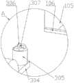
图3为图2中A处结构示意图;Fig. 3 is a schematic diagram of the structure at A in Fig. 2;
图4为图2中B处结构示意图;Fig. 4 is a schematic diagram of the structure at B in Fig. 2;
图5为本发明一实施例的夹持机构结构示意图;Fig. 5 is a schematic structural diagram of a clamping mechanism according to an embodiment of the present invention;
图6为本发明一实施例的第三矩形板与弧形储液管配合结构示意图;Fig. 6 is a schematic diagram of the cooperation structure of the third rectangular plate and the arc-shaped liquid storage tube according to an embodiment of the present invention;
图7为本发明一实施例的第一夹持组件与取样管配合结构示意图;Fig. 7 is a schematic diagram of the cooperative structure of the first clamping assembly and the sampling tube according to an embodiment of the present invention;
图8为本发明一实施例的第二夹持组件结构示意图;Fig. 8 is a schematic structural diagram of a second clamping assembly according to an embodiment of the present invention;
图9为本发明一实施例的漏斗与弧形储液管配合结构示意图。Fig. 9 is a schematic diagram of the cooperation structure of the funnel and the arc-shaped liquid storage tube according to an embodiment of the present invention.
具体实施方式Detailed ways
下面将结合本发明实施例中的附图,对本发明实施例中的技术方案进行清楚、完整地描述,显然,所描述的实施例仅仅是本发明一部分实施例,而不是全部的实施例。基于本发明中的实施例,本领域普通技术人员在没有作出创造性劳动前提下所获得的所有其它实施例,都属于本发明保护的范围。The following will clearly and completely describe the technical solutions in the embodiments of the present invention with reference to the accompanying drawings in the embodiments of the present invention. Obviously, the described embodiments are only some, not all, embodiments of the present invention. Based on the embodiments of the present invention, all other embodiments obtained by persons of ordinary skill in the art without creative efforts fall within the protection scope of the present invention.
为了保持本发明实施例的以下说明清楚且简明,本发明省略了已知功能和已知部件的详细说明,且本申请所涉及的用电器件均可通过蓄电池供电或外接电源。In order to keep the following description of the embodiments of the present invention clear and concise, the present invention omits detailed descriptions of known functions and known components, and the electrical devices involved in this application can be powered by batteries or external power sources.
请参阅图1、2所示,在本实施例中提供了一种医疗用尿液样本自动化采集设备,包括:壳体1,壳体1内设有储液管收集室103、样本采集室104,储液管收集室103与样本采集室104之间设有隔板,隔板上侧装设有传送机构2,传送机构2上装设有多个弧形储液管4,弧形储液管4的中部设有橡胶塞403;Please refer to Figures 1 and 2, in this embodiment, a medical urine sample automatic collection device is provided, including: a housing 1, a liquid storage
样本采集室104包括设于远离隔板一侧的侧板,侧板的宽度方向上开设有通孔101、与弧形储液管4相对应的通道102,通道102用于弧形储液管4的输送;样本采集室104内装设有第二驱动机构3,第二驱动机构3的输出端装设有第一夹持组件,第一夹持组件的上部装设有取样管8,取样管8内设有螺纹柱802。The
值得注意的是,本申请所附图纸,仅是为了说明结构原理,并不代表一定采用该图纸实施,为了提升用户体验,减少内部结构的裸露,减少气味的泄露,使得取样工作更加隐私化、人性化,对于增加对壳体1的覆盖程度的结构均在本申请的保护范围之内,本申请并不以此为限。It is worth noting that the drawings attached to this application are only to illustrate the structural principle, and do not mean that the drawings must be used for implementation. In order to improve the user experience, reduce the exposure of the internal structure, reduce the leakage of the smell, and make the sampling work more private. Humanization, structures that increase the degree of coverage of the housing 1 are within the protection scope of the present application, and the present application is not limited thereto.
如图2、3所示,本实施例的第二驱动机构3包括x、y轴平移组件,x、y轴平移组件的输出端装设有第一电动推杆303,第一电动推杆303的输出端装设有第二矩形板304,第二矩形板304的输出端装设有旋转电机305,第一夹持组件装设于旋转电机305的输出端。As shown in Figures 2 and 3, the
第一夹持组件包括装设于旋转电机305输出端的两第二夹持块306,且两第二夹持块306之间装设有第一弹簧307,如图7所示,取样管8底部装设有两凸块801。The first clamping assembly includes two
x、y轴平移组件包括装设于样本采集室104内壁横向方向的第一电动导轨301,第一电动导轨301的输出端装设有第二电动导轨302,且第一电动导轨301与第二电动导轨302位置上垂直,第一电动推杆303装设于第二电动导轨302的输出端。The x, y-axis translation assembly includes a first
具体的,第二夹持块306为矩形块结构,且该矩形块结构的端部设有楔形部,从而便于插入两凸块801之间;第二驱动机构3用于拿取取样管8,并将弧形储液管4内的尿液灌至取样管8内,然后提升至壳体1上方,便于用户取走。Specifically, the
如图3所示,本实施例的样本采集室104内壁开设有储物槽105,储物槽105两侧分别设有滑道、槽道,滑道内放置有多个取样管8,且滑道相对于水平面倾斜设置,储物槽105的槽口处设有挡板106。As shown in Figure 3, a
具体的,使用前将多个取样管8放置在滑道内,当第一夹持组件取走位于储物槽105槽口处的取样管8后,其后的取样管8依次滑落至槽口,从而便于下次拿取。Specifically, a plurality of
如图2、8所示,本实施例的传送机构2包括输送机,输送机包括输送带,输送带上均布有第二夹持组件。As shown in FIGS. 2 and 8 , the conveying
第二夹持组件包括设于输送带上的矩形块201,矩形块201上装设有第一矩形板202,第一矩形板202上装设有四个第一夹持块203,且四个第一夹持块203首尾依次通过第二弹簧204连接,且四个第一夹持块203之间形成一夹持空间,且该夹持空间从一端到另一端依次设有扩口、平口,扩口便于管体进入,平口用于稳定夹持,减少晃动。The second clamping assembly includes a
具体的,传送机构2用于输送弧形储液管4,使用前将多个弧形储液管4通过第二夹持组件安装在输送带周侧即可,值得注意的是,可将弧形储液管4安装在输送带下侧的第二夹持组件内,从而减少了散落尿液对传送机构2的污染。矩形块201由于与输送带的接触面积较小,所以当第二夹持组件被驱动经过输送带两端的弧形面时,顺畅度增加。弧形储液管4一端设有管体,用于被第二夹持组件夹持。Specifically, the
如图7所示,本实施例的弧形储液管4中部设有出口管402,且橡胶塞403位于出口管402内,且橡胶塞403的底部设有与螺纹柱802相配合的第一螺纹槽。As shown in Figure 7, an
取样管8的上部设有盖板,且盖板一面设有与螺纹柱802相配合的第二螺纹槽。The upper part of the
具体的,弧形储液管4在被放置时,中部的弯折处朝向下方,用户在向弧形储液管4内输送尿液时,其中段尿液会靠近弧形储液管4的中部,利于对位于弧形储液管4中部的尿液进行取样。Specifically, when the arc-shaped
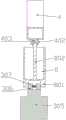
如图9所示,本实施例的通孔101靠近样本采集室104的一端为缩口,通孔101远离样本采集室104的一端为扩口,通孔101内放置有漏斗7,且漏斗7的缩口外径小于弧形储液管4的内径。As shown in Figure 9, the end of the through
具体的,漏斗7可用户自行放置或取走,也可通过机械手放置或取走,需要注意的是,该漏斗7可被其他能够折弯的物体替代,如具有防水薄膜且被弯折的硬质纸片,只要能将用户的尿液输送至弧形储液管4内即可。另一方面,可在壳体1一侧安装小型垃圾桶,用于放置漏斗7。Specifically, the funnel 7 can be placed or taken away by the user, or can be placed or taken away by a manipulator. It should be noted that the funnel 7 can be replaced by other objects that can be bent, such as a bent hard High-quality paper sheet, as long as the urine of the user can be delivered to the curved
如图4、6所示,本实施例的隔板靠近样本采集室104的一侧设有第一驱动机构6,第一驱动机构6包括位于隔板侧壁上的矩形条板,矩形条板上装设有第二电动推杆601,第二电动推杆601的输出端装设有推板602;As shown in Figures 4 and 6, the partition of this embodiment is provided with a
弧形储液管4横截面为矩形,弧形储液管4两侧对称设有开口,开口内滑动配合有第三矩形板401。The cross section of the arc-shaped
具体的,弧形储液管4在两开口之间的空间,所储存的尿液量,可与需要取样的尿液量相等,从而实现了定量取样的效果,且该尿液量小于取样管8的容积。Specifically, the amount of urine stored in the space between the two openings of the arc-shaped
如图5所示,本实施例的储液管收集室103上部装设有夹持机构5,夹持机构5包括第三电动推杆,第三电动推杆的输出端装设有机械手501,机械手501可采用常规机械手臂的设计,也可在第三电动推杆的输出端装设第四矩形板,在第四矩形板两侧分别装设固定块、夹块,需要夹取时,利用第四电动推杆推动夹块向固定块的方向移动,即可对管体进行夹持。As shown in Figure 5, the upper part of the liquid storage
具体的,夹持机构5用于将已被取样的弧形储液管4从传送机构2上取走,并放置在储液管收集室103内,该储液管收集室103内可放置抽屉,从而便于将废弃弧形储液管4转移走。Specifically, the
本实施例一个方面的应用为:The application of one aspect of this embodiment is:
取样前的准备工作,将弧形储液管4的管体部夹持在夹持空间内,驱动输送机以使弧形储液管4远离管体的一端对准通孔101;将取样管8放置在滑道内,驱动第二驱动机构3以使第一夹持组件向槽道内移动,然后驱动第一电动推杆303,第一电动推杆303带动第一夹持组件向滑道内移动,此时两第二夹持块306的楔形部进入一取样管8底部的两凸块801之间,此时第一弹簧307被逐渐压缩,进而两第二夹持块306的矩形块结构进入两凸块801之间,从而对取样管8起到夹持效果,然后第二电动导轨302驱动第一夹持组件向上移动以越过挡板106,然后第一电动导轨301带动取样管8移至弧形储液管4中部的橡胶塞403下方,驱动旋转电机305以使螺纹柱802的端部旋入第一螺纹槽内。Preparation work before sampling, clamp the tube body of the arc-shaped
取样时,将漏斗7的缩口处通过通孔101放置在弧形储液管4远离管体的一端内,排尿结束后,按压控制按钮,处理器接收到指令后,驱动第二电动推杆601以使推板602向靠近弧形储液管4的方向移动,直至推动第三矩形板401将开口封堵住,然后第二电动导轨302带动螺纹柱802向下移动,从而将橡胶塞403取下,此时两第三矩形板401之间的尿液经出口管402,并在螺纹柱802的引流作用下流入取样管8内,从而进一步减少了尿液的洒落;取样结束后,第二电动导轨302将螺纹柱802向上移动,从而使橡胶塞403再次进入出口管402内,然后旋转电机305倒转,完成螺纹柱802与橡胶塞403的分离,此时,第二电动导轨302将取样管8移至壳体1上方即可,用户可将盖板通过螺纹柱802盖在取样管8的管口处,并顺着楔形部的方向取下取样管8即可。When sampling, place the constriction of the funnel 7 through the through
取样结束后,驱动第三电动推杆向靠近管体的一侧移动,机械手501将管体夹持住,然后第三电动推杆带动机械手501向靠近储液管收集室103的一侧移动,此时,可利用机械手臂将弧形储液管4的端口封堵住,然后机械手501松开弧形储液管4,弧形储液管4掉落至储液管收集室103内,最后按照前述步骤进行取样前的准备工作即可。After the sampling is finished, drive the third electric push rod to move to the side close to the tube body, the
上述实施例可以相互结合。The above-described embodiments can be combined with each other.
需要说明的是,本申请的说明书和权利要求书及上述附图中的术语“第一”、“第二”等是用于区别类似的对象,而不必用于描述特定的顺序或先后次序。应该理解这样使用的数据在适当情况下可以互换,以便这里描述的本申请的实施方式能够以除了在这里图示或描述的那些以外的顺序实施。It should be noted that the terms "first" and "second" in the description and claims of the present application and the above drawings are used to distinguish similar objects, but not necessarily used to describe a specific sequence or sequence. It is to be understood that the data so used are interchangeable under appropriate circumstances such that the embodiments of the application described herein can be practiced in sequences other than those illustrated or described herein.
在本发明的描述中,需要理解的是,方位词如“前、后、上、下、左、右”、“横向、竖向、垂直、水平”和“顶、底”等所指示的方位或位置关系通常是基于附图所示的方位或位置关系,仅是为了便于描述本发明和简化描述,在未作相反说明的情况下,这些方位词并不指示和暗示所指的装置或元件必须具有特定的方位或者以特定的方位构造和操作,因此不能理解为对本发明保护范围的限制;方位词“内、外”是指相对于各部件本身的轮廓的内外。In the description of the present invention, it should be understood that orientation words such as "front, back, up, down, left, right", "horizontal, vertical, vertical, horizontal" and "top, bottom" etc. indicate the orientation Or positional relationship is generally based on the orientation or positional relationship shown in the drawings, and is only for the convenience of describing the present invention and simplifying the description. In the absence of a contrary description, these orientation words do not indicate or imply the device or element referred to. It must have a specific orientation or be constructed and operated in a specific orientation, so it should not be construed as limiting the protection scope of the present invention; the orientation words "inner and outer" refer to the inner and outer relative to the outline of each component itself.
以上公开的本发明优选实施例只是用于帮助阐述本发明。优选实施例并没有详尽叙述所有的细节,也不限制该发明仅为所述的具体实施方式。显然,根据本说明书的内容,可作很多的修改和变化。本说明书选取并具体描述这些实施例,是为了更好地解释本发明的原理和实际应用,从而使所属技术领域技术人员能很好地理解和利用本发明。本发明仅受权利要求书及其全部范围和等效物的限制。The preferred embodiments of the invention disclosed above are only to help illustrate the invention. The preferred embodiments are not exhaustive in all detail, nor are the inventions limited to specific embodiments described. Obviously, many modifications and variations can be made based on the contents of this specification. This description selects and specifically describes these embodiments in order to better explain the principle and practical application of the present invention, so that those skilled in the art can well understand and utilize the present invention. The invention is to be limited only by the claims, along with their full scope and equivalents.
Claims (5)
Translated fromChinesePriority Applications (1)
| Application Number | Priority Date | Filing Date | Title |
|---|---|---|---|
| CN202011013331.0ACN112180075B (en) | 2020-09-24 | 2020-09-24 | Automatic medical urine sample collecting equipment |
Applications Claiming Priority (1)
| Application Number | Priority Date | Filing Date | Title |
|---|---|---|---|
| CN202011013331.0ACN112180075B (en) | 2020-09-24 | 2020-09-24 | Automatic medical urine sample collecting equipment |
Publications (2)
| Publication Number | Publication Date |
|---|---|
| CN112180075A CN112180075A (en) | 2021-01-05 |
| CN112180075Btrue CN112180075B (en) | 2023-04-07 |
Family
ID=73956142
Family Applications (1)
| Application Number | Title | Priority Date | Filing Date |
|---|---|---|---|
| CN202011013331.0AActiveCN112180075B (en) | 2020-09-24 | 2020-09-24 | Automatic medical urine sample collecting equipment |
Country Status (1)
| Country | Link |
|---|---|
| CN (1) | CN112180075B (en) |
Families Citing this family (1)
| Publication number | Priority date | Publication date | Assignee | Title |
|---|---|---|---|---|
| CN119896500A (en)* | 2025-03-31 | 2025-04-29 | 连云港市第一人民医院 | Urine testing and processing device |
Family Cites Families (9)
| Publication number | Priority date | Publication date | Assignee | Title |
|---|---|---|---|---|
| CA1173272A (en)* | 1981-10-06 | 1984-08-28 | Rajko Kenda | Apparatus for separately catching successive streams of urine at taking samples to laboratorial and bacteriological examination |
| US5919146A (en)* | 1997-02-06 | 1999-07-06 | Tri-State Hospital Supply Corp. | Urine sampling and drainage device |
| EP3165247B1 (en)* | 2006-02-09 | 2020-10-28 | DEKA Products Limited Partnership | Pumping fluid delivery systems and methods using force application assembley |
| CN109313209B (en)* | 2015-12-18 | 2022-08-16 | 雅培实验室 | System and method for automated analysis |
| EP3196654B1 (en)* | 2016-01-22 | 2023-06-21 | Roche Diagnostics GmbH | Method and device for transferring sample tubes between a laboratory automation system and a sample archiving system |
| EP3519093B1 (en)* | 2016-09-30 | 2021-03-10 | Koninklijke Philips N.V. | System for applying a reagent to a sample |
| CN209377623U (en)* | 2018-12-20 | 2019-09-13 | 白玲玉 | A kind of obstetrics and gynecology department sampler |
| CN110074821B (en)* | 2019-04-25 | 2022-01-25 | 重庆医科大学附属第三医院(捷尔医院) | Urine sampling device for physical examination of pregnant woman |
| CN110736850A (en)* | 2019-10-31 | 2020-01-31 | 北京享云智汇科技有限公司 | kinds of urine detecting instrument |
- 2020
- 2020-09-24CNCN202011013331.0Apatent/CN112180075B/enactiveActive
Also Published As
| Publication number | Publication date |
|---|---|
| CN112180075A (en) | 2021-01-05 |
Similar Documents
| Publication | Publication Date | Title |
|---|---|---|
| CN112180075B (en) | Automatic medical urine sample collecting equipment | |
| CN206540729U (en) | A kind of urine sampler | |
| CN210204785U (en) | Clinical leucorrhea sample censorship device of gynaecology | |
| CN217066422U (en) | Urine sampling device is used in nephrology dept inspection | |
| CN114778195A (en) | A urine sampler for medical examination | |
| CN205038081U (en) | A disposable liquid collection device | |
| CN211668875U (en) | Urine three-cup test collection device | |
| CN209996367U (en) | Urine collector for clinical examination | |
| CN219516364U (en) | Female patient urine sampler | |
| CN210784435U (en) | Gynaecology's urine examination device | |
| CN211155898U (en) | Urine collector | |
| CN116491990A (en) | Urine device is got in special use of physical examination center women | |
| CN108324330A (en) | The Multifunctional body fluid of anti-cross infection collects feeding device for inspection | |
| CN211796614U (en) | Obstetrical clinical secretion sampling device | |
| CN211061269U (en) | Urine sampling device that medical science inspection was used | |
| CN220708829U (en) | Pollution-free urine sampling device for patient examination | |
| CN221154178U (en) | Urine specimen collection device | |
| CN114451932A (en) | A body private department sampling equipment for gynaecology | |
| CN108652682B (en) | A kind of automatic collection equipment of urine sample for hospital | |
| CN213180725U (en) | Vomitus sampling device for gastroenterology | |
| CN208140433U (en) | A kind of self-sealing urine collector | |
| CN221725598U (en) | A disposable sterile feces collection bottle | |
| CN219147670U (en) | Urine sample collector | |
| CN221555941U (en) | Blood sampling sample collection management device for physical examination nursing | |
| CN201497661U (en) | Urine sampling device |
Legal Events
| Date | Code | Title | Description |
|---|---|---|---|
| PB01 | Publication | ||
| PB01 | Publication | ||
| SE01 | Entry into force of request for substantive examination | ||
| SE01 | Entry into force of request for substantive examination | ||
| GR01 | Patent grant | ||
| GR01 | Patent grant |