CN112168511B - Restraint device for wheelchair occupant - Google Patents
Restraint device for wheelchair occupantDownload PDFInfo
- Publication number
- CN112168511B CN112168511BCN202010326545.7ACN202010326545ACN112168511BCN 112168511 BCN112168511 BCN 112168511BCN 202010326545 ACN202010326545 ACN 202010326545ACN 112168511 BCN112168511 BCN 112168511B
- Authority
- CN
- China
- Prior art keywords
- wheelchair
- occupant
- buckle
- retractor
- belt
- Prior art date
- Legal status (The legal status is an assumption and is not a legal conclusion. Google has not performed a legal analysis and makes no representation as to the accuracy of the status listed.)
- Expired - Fee Related
Links
Images


Classifications
- A—HUMAN NECESSITIES
- A61—MEDICAL OR VETERINARY SCIENCE; HYGIENE
- A61G—TRANSPORT, PERSONAL CONVEYANCES, OR ACCOMMODATION SPECIALLY ADAPTED FOR PATIENTS OR DISABLED PERSONS; OPERATING TABLES OR CHAIRS; CHAIRS FOR DENTISTRY; FUNERAL DEVICES
- A61G3/00—Ambulance aspects of vehicles; Vehicles with special provisions for transporting patients or disabled persons, or their personal conveyances, e.g. for facilitating access of, or for loading, wheelchairs
- A61G3/08—Accommodating or securing wheelchairs or stretchers
- A61G3/0808—Accommodating or securing wheelchairs
- B—PERFORMING OPERATIONS; TRANSPORTING
- B60—VEHICLES IN GENERAL
- B60R—VEHICLES, VEHICLE FITTINGS, OR VEHICLE PARTS, NOT OTHERWISE PROVIDED FOR
- B60R22/00—Safety belts or body harnesses in vehicles
- B60R22/48—Control systems, alarms, or interlock systems, for the correct application of the belt or harness
- A—HUMAN NECESSITIES
- A61—MEDICAL OR VETERINARY SCIENCE; HYGIENE
- A61F—FILTERS IMPLANTABLE INTO BLOOD VESSELS; PROSTHESES; DEVICES PROVIDING PATENCY TO, OR PREVENTING COLLAPSING OF, TUBULAR STRUCTURES OF THE BODY, e.g. STENTS; ORTHOPAEDIC, NURSING OR CONTRACEPTIVE DEVICES; FOMENTATION; TREATMENT OR PROTECTION OF EYES OR EARS; BANDAGES, DRESSINGS OR ABSORBENT PADS; FIRST-AID KITS
- A61F5/00—Orthopaedic methods or devices for non-surgical treatment of bones or joints; Nursing devices ; Anti-rape devices
- A61F5/37—Restraining devices for the body or for body parts; Restraining shirts
- A61F5/3769—Restraining devices for the body or for body parts; Restraining shirts for attaching the body to beds, wheel-chairs or the like
- A61F5/3776—Restraining devices for the body or for body parts; Restraining shirts for attaching the body to beds, wheel-chairs or the like by means of a blanket or belts
- A—HUMAN NECESSITIES
- A61—MEDICAL OR VETERINARY SCIENCE; HYGIENE
- A61F—FILTERS IMPLANTABLE INTO BLOOD VESSELS; PROSTHESES; DEVICES PROVIDING PATENCY TO, OR PREVENTING COLLAPSING OF, TUBULAR STRUCTURES OF THE BODY, e.g. STENTS; ORTHOPAEDIC, NURSING OR CONTRACEPTIVE DEVICES; FOMENTATION; TREATMENT OR PROTECTION OF EYES OR EARS; BANDAGES, DRESSINGS OR ABSORBENT PADS; FIRST-AID KITS
- A61F5/00—Orthopaedic methods or devices for non-surgical treatment of bones or joints; Nursing devices ; Anti-rape devices
- A61F5/37—Restraining devices for the body or for body parts; Restraining shirts
- A61F5/3769—Restraining devices for the body or for body parts; Restraining shirts for attaching the body to beds, wheel-chairs or the like
- A61F5/3792—Restraining devices for the body or for body parts; Restraining shirts for attaching the body to beds, wheel-chairs or the like to chairs, e.g. wheelchairs
- B—PERFORMING OPERATIONS; TRANSPORTING
- B60—VEHICLES IN GENERAL
- B60R—VEHICLES, VEHICLE FITTINGS, OR VEHICLE PARTS, NOT OTHERWISE PROVIDED FOR
- B60R22/00—Safety belts or body harnesses in vehicles
- B60R22/12—Construction of belts or harnesses
- B—PERFORMING OPERATIONS; TRANSPORTING
- B60—VEHICLES IN GENERAL
- B60R—VEHICLES, VEHICLE FITTINGS, OR VEHICLE PARTS, NOT OTHERWISE PROVIDED FOR
- B60R22/00—Safety belts or body harnesses in vehicles
- B60R22/18—Anchoring devices
- B—PERFORMING OPERATIONS; TRANSPORTING
- B60—VEHICLES IN GENERAL
- B60R—VEHICLES, VEHICLE FITTINGS, OR VEHICLE PARTS, NOT OTHERWISE PROVIDED FOR
- B60R22/00—Safety belts or body harnesses in vehicles
- B60R22/34—Belt retractors, e.g. reels
- B60R22/343—Belt retractors, e.g. reels with electrically actuated locking means
- B—PERFORMING OPERATIONS; TRANSPORTING
- B60—VEHICLES IN GENERAL
- B60R—VEHICLES, VEHICLE FITTINGS, OR VEHICLE PARTS, NOT OTHERWISE PROVIDED FOR
- B60R22/00—Safety belts or body harnesses in vehicles
- B60R22/34—Belt retractors, e.g. reels
- B60R22/347—Belt retractors, e.g. reels with means for permanently locking the retractor during the wearing of the belt
- B60R22/35—Belt retractors, e.g. reels with means for permanently locking the retractor during the wearing of the belt the locking means being automatically actuated
- B60R22/357—Belt retractors, e.g. reels with means for permanently locking the retractor during the wearing of the belt the locking means being automatically actuated in response to fastening of the belt buckle
- A—HUMAN NECESSITIES
- A61—MEDICAL OR VETERINARY SCIENCE; HYGIENE
- A61G—TRANSPORT, PERSONAL CONVEYANCES, OR ACCOMMODATION SPECIALLY ADAPTED FOR PATIENTS OR DISABLED PERSONS; OPERATING TABLES OR CHAIRS; CHAIRS FOR DENTISTRY; FUNERAL DEVICES
- A61G2200/00—Information related to the kind of patient or his position
- A61G2200/30—Specific positions of the patient
- A61G2200/34—Specific positions of the patient sitting
- A—HUMAN NECESSITIES
- A61—MEDICAL OR VETERINARY SCIENCE; HYGIENE
- A61G—TRANSPORT, PERSONAL CONVEYANCES, OR ACCOMMODATION SPECIALLY ADAPTED FOR PATIENTS OR DISABLED PERSONS; OPERATING TABLES OR CHAIRS; CHAIRS FOR DENTISTRY; FUNERAL DEVICES
- A61G2203/00—General characteristics of devices
- A61G2203/30—General characteristics of devices characterised by sensor means
- A61G2203/36—General characteristics of devices characterised by sensor means for motion
- B—PERFORMING OPERATIONS; TRANSPORTING
- B60—VEHICLES IN GENERAL
- B60R—VEHICLES, VEHICLE FITTINGS, OR VEHICLE PARTS, NOT OTHERWISE PROVIDED FOR
- B60R22/00—Safety belts or body harnesses in vehicles
- B60R22/48—Control systems, alarms, or interlock systems, for the correct application of the belt or harness
- B60R2022/4808—Sensing means arrangements therefor
- B60R2022/4816—Sensing means arrangements therefor for sensing locking of buckle
Landscapes
- Health & Medical Sciences (AREA)
- Engineering & Computer Science (AREA)
- Public Health (AREA)
- Mechanical Engineering (AREA)
- Animal Behavior & Ethology (AREA)
- Life Sciences & Earth Sciences (AREA)
- General Health & Medical Sciences (AREA)
- Veterinary Medicine (AREA)
- Heart & Thoracic Surgery (AREA)
- Vascular Medicine (AREA)
- Biomedical Technology (AREA)
- Orthopedic Medicine & Surgery (AREA)
- Nursing (AREA)
- Textile Engineering (AREA)
- Automation & Control Theory (AREA)
- Automotive Seat Belt Assembly (AREA)
Abstract
Description
Translated fromChinese技术领域technical field
本发明涉及轮椅乘坐者用约束装置。The present invention relates to a restraint device for a wheelchair occupant.
背景技术Background technique
在日本特开2017-148445中公开了一种通过束缚带(轮椅用带构件)使轮椅束缚于车厢地板并通过乘坐者安全带(乘坐者用带构件)约束乘坐者的轮椅固定装置。此外,在日本特开2018-90143中公开了一种通过带使轮椅固定(束缚)于地板并使座椅安全带绕在落座于轮椅的乘坐者的身体来约束乘坐者的构造。Japanese Patent Application Laid-Open No. 2017-148445 discloses a wheelchair fixing device that restrains a wheelchair to the floor of a vehicle compartment with a restraint belt (belt member for a wheelchair) and restrains an occupant with a seat belt for an occupant (belt member for a passenger). In addition, JP 2018-90143 discloses a structure in which a wheelchair is fixed (constrained) to the floor by a belt and a seat belt is wound around the body of the occupant seated in the wheelchair to restrain the occupant.
然而,在约束乘坐者之后再束缚轮椅的情况下,有时因乘坐者的身体活动被限制而难以进行操作。此外,有时会忘记束缚轮椅,因此存在改善的余地。However, in the case of restraining the wheelchair after restraining the occupant, it may be difficult to operate because the physical activity of the occupant is restricted. In addition, wheelchairs are sometimes forgotten to be restrained, so there is room for improvement.
发明内容Contents of the invention
本发明考虑到上述事实,其目的在于得到一种能抑制忘记束缚轮椅并且高效地进行轮椅的束缚和乘坐者的约束的轮椅乘坐者用约束装置。The present invention takes the above circumstances into consideration, and an object of the present invention is to obtain a restraint device for a wheelchair occupant that can suppress forgetting to restrain the wheelchair and perform restraint of the wheelchair and restraint of the occupant efficiently.
方案1的轮椅乘坐者用约束装置具有:轮椅用卷收器,将轮椅用带构件的一端部以能拉出的方式卷取;轮椅用带扣,能供装配于所述轮椅用带构件的另一端部的轮椅用舌板装接;乘坐者用卷收器,将乘坐者用带构件的一端部以能拉出的方式卷取;乘坐者用带扣,能供装配于所述乘坐者用带构件的另一端部的乘坐者用舌板装接;带扣传感器,对所述轮椅用舌板已被装接于所述轮椅用带扣进行感测;以及乘坐者用带锁定机构,被配置为能对将所述乘坐者用带构件设为不能拉出的锁定状态和将所述乘坐者用带构件设为能拉出的锁定解除状态进行切换,在通过所述带扣传感器感测到所述轮椅用舌板已被装接于所述轮椅用带扣的情况下,从所述锁定状态向所述锁定解除状态切换。The restraint device for a wheelchair occupant according to claim 1 includes: a retractor for a wheelchair that retracts one end of a belt member for a wheelchair so that it can be pulled out; a belt buckle for a wheelchair that can be attached to the belt member for a wheelchair; The other end of the wheelchair is connected with a tongue plate; the occupant uses a retractor to take up one end of the occupant's belt member in a pull-out manner; the occupant's buckle is capable of being assembled on the occupant an occupant tongue attached to the other end of the belt member; a buckle sensor that senses that the wheelchair tongue has been attached to the wheelchair buckle; and an occupant belt locking mechanism, configured to switch between a locked state in which the occupant belt member cannot be pulled out and an unlocked state in which the occupant belt member can be pulled out, and is sensed by the buckle sensor. When it is detected that the wheelchair tongue is attached to the wheelchair buckle, the locked state is switched to the unlocked state.
在方案1的轮椅乘坐者用约束装置中,轮椅用带构件的一端部以能拉出的方式被轮椅用卷收器卷取,在轮椅用带构件的另一端部装配有轮椅用舌板。此外,轮椅用舌板被设为能装接于轮椅用带扣。由此,从轮椅用卷收器拉出轮椅用带构件并使该轮椅用带构件越过轮椅的框架,将轮椅用舌板装接于轮椅用带扣,就能束缚轮椅。In the restraint device for a wheelchair occupant according to claim 1, one end of the wheelchair belt member is pulled out by the wheelchair retractor, and the wheelchair tongue is attached to the other end of the wheelchair belt member. In addition, the tongue plate for a wheelchair is configured to be attachable to the buckle for a wheelchair. Thereby, the wheelchair belt member is pulled out from the wheelchair retractor, passed over the wheelchair frame, and the wheelchair tongue plate is attached to the wheelchair buckle, thereby constraining the wheelchair.
另一方面,乘坐者用带构件的一端部以能拉出的方式被乘坐者用卷收器卷取,在乘坐者用带构件的另一端部装配有乘坐者用舌板。并且,乘坐者用舌板被设为能装接于乘坐者用带扣。由此,从乘坐者用卷收器拉出乘坐者用带构件并将乘坐者用舌板装接于乘坐者用带扣,就能约束轮椅的乘坐者。On the other hand, one end portion of the seat belt member is pulled out by the seat retractor, and the seat tongue plate is attached to the other end portion of the seat belt member. In addition, the occupant's tongue is configured to be attachable to the occupant's buckle. Accordingly, the occupant of the wheelchair can be restrained by pulling out the occupant belt member from the occupant retractor and attaching the occupant tongue plate to the occupant buckle.
此外,在通过带扣传感器感测到轮椅用舌板已被装接于轮椅用带扣的情况下,能通过乘坐者用带锁定机构从锁定状态向锁定解除状态切换。由此,不能在束缚轮椅之前拉出乘坐者用带构件,能抑制忘记束缚。而且,由于在进行轮椅的束缚后进行乘坐者的约束,因此在进行轮椅的束缚时乘坐者的身体活动不会被限制。In addition, when the buckle sensor senses that the wheelchair tongue is attached to the wheelchair buckle, it is possible to switch from the locked state to the unlocked state by the occupant belt lock mechanism. Thereby, the occupant's belt member cannot be pulled out before the wheelchair is restrained, and it is possible to suppress forgetting to restrain the wheelchair. Furthermore, since the occupant is restrained after the wheelchair is restrained, the occupant's physical activity is not restricted during the wheelchair restraint.
对于方案2的轮椅乘坐者用约束装置,在方案1中,所述乘坐者用带锁定机构被配置为能对所述锁定状态和所述锁定解除状态进行电切换。In the wheelchair occupant restraint device of claim 2, in claim 1, the occupant belt locking mechanism is configured to be electrically switchable between the locked state and the unlocked state.
在方案2的轮椅乘坐者用约束装置中,与机械地切换乘坐者用带构件的锁定状态和锁定解除状态的构成相比,能实现简易的构造。In the restraint device for a wheelchair occupant of claim 2, a simpler structure can be realized compared to a configuration in which the locked state and the unlocked state of the occupant belt member are mechanically switched.
对于方案3的轮椅乘坐者用约束装置,在方案1或2中,具备轮椅用带锁定机构,所述轮椅用带锁定机构在通过所述带扣传感器感测到所述轮椅用舌板已被装接于所述轮椅用带扣的情况下,使所述轮椅用带构件不能从所述轮椅用卷收器拉出。Regarding the restraint device for wheelchair occupants of Plan 3, in Plan 1 or 2, a wheelchair belt locking mechanism is provided, and the wheelchair belt locking mechanism senses that the wheelchair tongue has been locked by the buckle sensor. When attached to the wheelchair buckle, the wheelchair belt member cannot be pulled out from the wheelchair retractor.
在方案3的轮椅乘坐者用约束装置中,仅通过将轮椅用舌板装接于轮椅用带扣,就能通过轮椅用带锁定机构使轮椅用带构件不能拉出。In the restraint device for a wheelchair occupant of claim 3, simply by attaching the wheelchair tongue plate to the wheelchair buckle, the wheelchair belt member cannot be pulled out by the wheelchair belt lock mechanism.
对于方案4的轮椅乘坐者用约束装置,在方案1~3中的任一项中,所述轮椅用带扣和所述乘坐者用带扣配设于立起设置在车厢内的立设构件且配设于落座在轮椅的乘坐者的手够得到的高度。Regarding the restraint device for a wheelchair occupant according to the fourth proposal, in any one of the proposals 1 to 3, the buckle for the wheelchair and the buckle for the occupant are arranged on an erecting member erected in the compartment And it is arranged at a height within reach of the hand of the occupant seated in the wheelchair.
在方案4的轮椅乘坐者用约束装置中,落座于轮椅的乘坐者能从配设于立设构件的轮椅用卷收器拉出轮椅用带构件。此外同样地,落座于轮椅的乘坐者能从乘坐者用卷收器拉出乘坐者用带构件。需要说明的是,在此所说的“落座于轮椅的乘坐者的手够得到的高度”是指标准体型的成人女性在落座于轮椅的状态下手够得到的高度。In the restraint device for a wheelchair occupant of claim 4, the occupant seated in the wheelchair can pull out the belt member for the wheelchair from the retractor for the wheelchair arranged on the upright member. In addition, similarly, the occupant seated in the wheelchair can pull out the belt member for the occupant from the retractor for the occupant. It should be noted that the "reachable height of the hand of the occupant seated in the wheelchair" referred to here refers to the height at which the hand of an adult woman with a standard body can reach when sitting in the wheelchair.
对于方案5的轮椅乘坐者用约束装置,在方案4中,所述乘坐者用卷收器和所述轮椅用带扣在车辆上下方向上配设于不同的高度。In the wheelchair occupant restraint device of claim 5, in claim 4, the retractor for the passenger and the buckle for the wheelchair are arranged at different heights in the vertical direction of the vehicle.
在方案5的轮椅乘坐者用约束装置中,通过将乘坐者用卷收器和轮椅用带扣配设于不同的高度,在束缚轮椅之后从乘坐者用卷收器拉出乘坐者用带构件来约束乘坐者时,轮椅用带构件不易成为障碍。In the restraint device for a wheelchair occupant according to claim 5, by arranging the retractor for the occupant and the buckle for the wheelchair at different heights, the belt member for the occupant is pulled out from the retractor for the occupant after the wheelchair is restrained. When restraining the occupant, the wheelchair belt member is less likely to become an obstacle.
如以上所说明的,根据方案1的轮椅乘坐者用约束装置,能抑制忘记束缚轮椅并且高效地进行轮椅的束缚和乘坐者的约束。As described above, according to the restraint device for a wheelchair occupant of claim 1, restraint of the wheelchair and restraint of the occupant can be efficiently performed while suppressing forgetting to restrain the wheelchair.
根据方案2的轮椅乘坐者用约束装置,与机械地切换乘坐者用带构件的锁定状态和锁定解除状态的构成相比,能使乘坐者用带锁定机构小型化。According to the restraint device for a wheelchair occupant of claim 2, the seat belt locking mechanism can be downsized compared to a configuration in which the seat belt member is mechanically switched between the locked state and the unlocked state.
根据方案3的轮椅乘坐者用约束装置,乘坐者无需进行特别的操作就能使轮椅用带构件的拉出锁定。According to the restraint device for a wheelchair occupant of claim 3, the occupant can pull out and lock the belt member for the wheelchair without performing a special operation.
根据方案4的轮椅乘坐者用约束装置,能通过落座于轮椅的乘坐者的手来进行轮椅的束缚。According to the restraint device for a wheelchair occupant of claim 4, the wheelchair can be restrained by the hands of the occupant seated on the wheelchair.
根据方案5的轮椅乘坐者用约束装置,与乘坐者用卷收器和轮椅用带扣配设于相同高度的构造相比,能顺畅地进行乘坐者的约束。According to the restraint device for a wheelchair occupant of claim 5, the occupant can be restrained more smoothly than the structure in which the retractor for the occupant and the buckle for the wheelchair are arranged at the same height.
附图说明Description of drawings
下面参照附图,对本发明的示例性实施例的特征、优点以及技术和工业意义进行说明,在附图中相同的附图标记表示相同的元件,其中,The features, advantages and technical and industrial significance of exemplary embodiments of the present invention are described below with reference to the accompanying drawings, in which the same reference numerals represent the same elements, wherein,
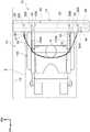
图1是从车辆宽度方向观察应用了实施方式的轮椅乘坐者用约束装置的车辆的车厢内的侧视图。FIG. 1 is a side view of the interior of a vehicle to which a restraint device for a wheelchair occupant according to an embodiment is applied, viewed from the vehicle width direction.
图2是从车辆上方观察应用了实施方式的轮椅乘坐者用约束装置的车辆的车厢内的俯视图。2 is a plan view of the interior of a vehicle to which the restraint device for a wheelchair occupant according to the embodiment is applied, viewed from above the vehicle.
图3是表示实施方式的轮椅乘坐者用约束装置的硬件构成的框图。3 is a block diagram showing the hardware configuration of the restraint device for a wheelchair occupant according to the embodiment.
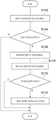
图4是表示约束乘坐者的情况下的锁定切换处理的流程图。Fig. 4 is a flowchart showing a lock switching process when a passenger is restrained.
图5是表示乘坐者约束状态下的紧急时的锁定切换处理的流程图。FIG. 5 is a flowchart showing an emergency lock switching process in the occupant restraint state.
图6是表示实施方式的轮椅乘坐者用约束装置的第一变形例的、与图1对应的侧视图。Fig. 6 is a side view corresponding to Fig. 1 , showing a first modified example of the restraint device for a wheelchair occupant according to the embodiment.
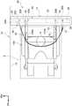
图7是表示实施方式的轮椅乘坐者用约束装置的第二变形例的、与图2对应的俯视图。Fig. 7 is a plan view corresponding to Fig. 2 , showing a second modified example of the restraint device for a wheelchair occupant of the embodiment.
具体实施方式Detailed ways
以下,参照附图对实施方式的轮椅乘坐者用约束装置10进行说明。需要说明的是,各图的箭头FR、箭头UP以及箭头RH分别表示应用了轮椅乘坐者用约束装置的车辆的行进方向(车辆前侧)、车辆上侧以及车辆右侧。在使用前后左右上下的方向进行说明的情况下,除非另有说明,否则表示车辆前后方向的前后、朝向行进方向的状态下的左右、车辆上下方向的上下。Hereinafter, a
如图1和图2所示,在应用了本实施方式的轮椅乘坐者用约束装置10的车辆12中设定有用于束缚轮椅100的束缚空间S,在束缚空间S的后方侧设有作为立设构件的立壁14。As shown in FIGS. 1 and 2, a restraint space S for restraining the
立壁14立起设置于地板面板16并在车辆上下方向和车辆宽度方向延伸,被配置为包括带固定板20、支承板22以及罩24。带固定板20位于立壁14的下部,以车辆前后方向为板厚方向沿车辆宽度方向延伸。此外,带固定板20的车辆右侧的端部固定于车厢侧壁18,带固定板20的车辆左侧的端部固定于作为立起设置于地板面板16的立设构件的扶手26。The standing
扶手26形成为大致圆柱状,延伸至车辆12的顶棚部。此外,在扶手26固定有支承板22的车辆左侧的端部。The
支承板22位于立壁14的上部,构成能从车辆后方侧支承轮椅100的承受面。具体而言,支承板22以车辆前后方向为板厚方向在比带固定板20靠车辆前方侧沿车辆宽度方向延伸。此外,支承板22的车辆右侧的端部固定于车厢侧壁18,支承板22的车辆左侧的端部如上所述地固定于扶手26。The
罩24为内装饰件,立起设置于地板面板16。并且,带固定板20和支承板22的整体被该罩24覆盖。The
在此,在带固定板20装配有轮椅用卷收器30、轮椅用带扣32、乘坐者用卷收器34以及乘坐者用带扣36。需要说明的是,在图1中,为了便于说明,将轮椅用卷收器30和轮椅用带扣32的高度描绘为不同的高度,但在本实施方式中配设于大致相同的高度。同样,将乘坐者用卷收器34和乘坐者用带扣36的高度描绘为不同的高度,但在本实施方式中配设于大致相同的高度。Here, a
第一装配片20A从带固定板20的下端部向车辆前方侧延伸出。如图2所示,第一装配片20A相对于束缚空间S设于车辆右侧。在此所说的“相对于束缚空间S的车辆右侧”是指比束缚空间S的车辆宽度方向的中心靠车辆右侧。并且,轮椅用卷收器30通过螺栓和螺母被紧固于该第一装配片20A。The
如图1所示,轮椅用卷收器30具备卷筒30A,轮椅用带构件31的一端部以能拉出的方式被卷取于该卷筒30A。卷筒30A被未图示的复位弹簧向卷取轮椅用带构件31的方向施力,因此轮椅用带构件31成为在无负荷状态下除了另一端部之外均被轮椅用卷收器30卷取的状态。在此,在本实施方式中作为一个例子,轮椅用卷收器30以倾斜的状态被紧固于第一装配片20A,以便向车辆前方侧且向车辆上方侧倾斜地拉出轮椅用带构件31。As shown in FIG. 1 , the
此外,轮椅用卷收器30具备紧急锁定机构(ELR:Emergency Locking Retractor),所述紧急锁定机构被配置为:在车辆12碰撞时等轮椅用带构件31突然拉出时,限制该轮椅用带构件31的拉出。而且,轮椅用卷收器30具备对轮椅用带构件31的拉出进行锁定和解除锁定的轮椅用带锁定机构63(参照图3)。该轮椅用带锁定机构63被配置为能对将轮椅用带构件31设为不能拉出的锁定状态和将轮椅用带构件31设为能拉出的锁定解除状态进行电切换。作为这样的锁定机构,在本实施方式中采用使用了螺线管和锁定杆的轮椅用带锁定机构63。在该轮椅用带锁定机构63中,通过对螺线管通电来驱动锁定杆而使卷筒30A成为锁定解除状态,另一方面在未对螺线管通电的情况下,锁定杆向相反侧移动而使卷筒30A成为锁定状态。In addition, the
轮椅用带构件31以与用于约束乘坐者P的织带相同的布料形成为长条状。即,轮椅用带构件31以与后述的乘坐者用带构件35相同的布料形成。此外,在本实施方式中作为一个例子,在轮椅用带构件31的一个面上描绘有模仿轮椅的标记,从而能直观地识别出是用于束缚轮椅100的安全带。而且,在轮椅用带构件31的另一端部装配有轮椅用舌板33。The
如图2所示,在比第一装配片20A靠车辆左侧设有第二装配片20B。第二装配片20B与第一装配片20A同样地从带固定板20的下端部向车辆前方侧延伸出,轮椅用带扣32通过螺栓和螺母被紧固于该第二装配片20B。As shown in FIG. 2 , the
轮椅用带扣32相对于束缚空间S配设于轮椅用卷收器30的相反侧,轮椅用舌板33能装接于该轮椅用带扣32。此外,在轮椅用带扣32设有带扣传感器64(参照图3),所述带扣传感器64对轮椅用舌板33已被装接于轮椅用带扣32进行感测。需要说明的是,在此所说的“相对于束缚空间S的、轮椅用卷收器30的相反侧”是指相对于束缚空间S的车辆宽度方向的中心的、轮椅用卷收器30的相反侧。此外,对于本实施方式的轮椅用带扣32而言,为了易于装接轮椅用舌板33,轮椅用带扣32以倾斜的状态被紧固于第二装配片20B,以便轮椅用舌板33的插入孔倾斜地朝向车辆前方侧且朝向车辆上方侧。The
在图1和图2中,图示出轮椅用舌板33越过轮椅100的框架100A装接于轮椅用带扣32的状态,在该状态下轮椅100被束缚。In FIGS. 1 and 2 , a state in which the
在比第二装配片20B靠车辆左侧设有第三装配片20C。第三装配片20C从带固定板20的上端部向车辆前方侧延伸出,乘坐者用卷收器34通过螺栓和螺母被紧固于该第三装配片20C。即,乘坐者用卷收器34配设于比轮椅用带扣32远离束缚空间S的位置。此外,乘坐者用卷收器34配设于比轮椅用带扣32靠车辆上方侧。The
如图1所示,乘坐者用卷收器34具备卷筒34A,乘坐者用带构件35的一端部以能拉出的方式被卷取于该卷筒34A。卷筒34A被未图示的复位弹簧向卷取乘坐者用带构件35的方向施力,因此乘坐者用带构件35成为在无负荷状态下除了另一端部之外均被乘坐者用卷收器34卷取的状态。在此,在本实施方式中作为一个例子,乘坐者用卷收器34以倾斜的状态被紧固于第三装配片20C,以便向车辆前方侧且向车辆上方侧倾斜地拉出乘坐者用带构件35。As shown in FIG. 1 , the
此外,乘坐者用卷收器34具备紧急锁定机构(ELR:Emergency LockingRetractor),该紧急情况锁定机构被配置为:在车辆12碰撞时等乘坐者用带构件35突然拉出时,限制该乘坐者用带构件35的拉出。In addition, the
在此,乘坐者用卷收器34具备对乘坐者用带构件35的拉出进行锁定和解除锁定的乘坐者用带锁定机构62(参照图3)。该乘坐者用带锁定机构62被配置为能对将乘坐者用带构件35设为不能拉出的锁定状态和将乘坐者用带构件35设为能拉出的锁定解除状态进行电切换。作为这样的锁定机构,在本实施方式中采用使用了螺线管和锁定杆的乘坐者用带锁定机构62。在该乘坐者用带锁定机构62中,通过对螺线管通电来驱动锁定杆而使卷筒34A成为锁定解除状态,另一方面在未对螺线管通电的情况下,锁定杆向相反侧移动而使卷筒34A成为锁定状态。Here, the
如图2所示,在比第一装配片20A靠车辆右侧设有第四装配片20D。第四装配片20D与第三装配片20C同样地从带固定板20的上端部向车辆前方侧延伸出,乘坐者用带扣36通过螺栓和螺母被紧固于该第四装配片20D。即,乘坐者用带扣36配设于比轮椅用卷收器30远离束缚空间S的位置。此外,乘坐者用带扣36配设于比轮椅用卷收器30靠车辆上方侧。As shown in FIG. 2 , a
乘坐者用带扣36相对于束缚空间S配设于乘坐者用卷收器34的相反侧。此外,装配于乘坐者用带构件35的另一端部的乘坐者用舌板37能装接于乘坐者用带扣36。此外,对于本实施方式的乘坐者用带扣36而言,为了易于装接乘坐者用舌板37,乘坐者用带扣36以倾斜的状态被紧固于第四装配片20D,以便乘坐者用舌板37的插入孔倾斜地朝向车辆前方侧且朝向车辆上方侧。The
如以上那样,在本实施方式中,轮椅用卷收器30、轮椅用带扣32、乘坐者用卷收器34以及乘坐者用带扣36配设于构成立壁14的带固定板20。因此,落座于轮椅100的乘坐者P的手够得到轮椅用卷收器30、轮椅用带扣32、乘坐者用卷收器34以及乘坐者用带扣36。As described above, in the present embodiment, the
图3是表示轮椅乘坐者用约束装置10的硬件构成的框图。如该图3所示,轮椅乘坐者用约束装置10具备作为控制部的ECU(Electrical Control Unit:电子控制单元)50。此外,ECU50被配置为包括CPU(Central Processing Unit:中央处理单元)52、ROM(Read OnlyMemory:只读存储器)54、RAM(Random Access Memory:随机存取存储器)56、存储器(Storage)58以及输入输出接口60。各构成经由总线51相互可通信地连接。FIG. 3 is a block diagram showing a hardware configuration of the
CPU52为中央运算处理单元,执行各种程序或者控制各部。即,CPU52从ROM54或存储器58读出程序,将RAM56作为作业区域来执行程序。CPU52按照记录于ROM54或存储器58的程序来进行上述各构成的控制和各种运算处理。The
ROM54储存各种程序和各种数据。RAM56作为作业区域临时存储程序或数据。存储器58由HDD(Hard Disk Drive:硬盘驱动器)或SSD(Solid State Drive:固态驱动器)构成,储存包括操作系统的各种程序和各种数据。在本实施方式中,在ROM54或存储器58储存有在约束乘坐者P的情况下对乘坐者用带锁定机构62进行切换的锁定切换处理程序和在乘坐者约束状态下的紧急时对乘坐者用带锁定机构62进行切换的锁定切换处理程序等。The
在输入输出接口60连接有乘坐者用带锁定机构62(乘坐者用卷收器34)、轮椅用带锁定机构63以及带扣传感器64(轮椅用带扣32)。此外,在输入输出接口60连接有对作用于车辆12的加速度进行检测的加速度传感器66。并且,基于来自ECU50的信号进行乘坐者用卷收器34的控制。A seat belt lock mechanism 62 (seat retractor 34 ), a wheelchair
(锁定切换处理的一个例子)(An example of lock switching processing)
在此,在通过带扣传感器64感测到轮椅用舌板33已被装接于轮椅用带扣32的情况下,ECU50通过乘坐者用带锁定机构62将乘坐者用带构件35从锁定状态向锁定解除状态切换。此外,在通过加速度传感器66检测到的加速度为规定值以上的情况和车辆12相对于水平的角度(倾斜)为规定值以上的情况中的至少一种情况下,ECU50通过乘坐者用带锁定机构62对乘坐者用带构件35的拉出进行锁定。参照图4和图5的流程图对该锁定切换处理的一个例子进行说明。CPU52从ROM54或存储器58读出锁定切换程序,在RAM56中展开并执行该锁定切换程序,由此执行该锁定切换处理。首先,参照图4对约束乘坐者P的情况下的锁定切换处理进行说明,接着参照图5对紧急时的锁定切换处理进行说明。Here, when the
如图4所示,在步骤S102中,CPU52通过乘坐者用带锁定机构62使乘坐者用带构件35的拉出锁定。即,将乘坐者用带锁定机构62切换为锁定状态。在乘坐者用带锁定机构62为锁定状态的情况下,维持锁定状态。As shown in FIG. 4 , in step S102 , the
CPU52在步骤S104中判断轮椅用带扣32的带扣传感器64是否打开。通过轮椅用舌板33被装接于轮椅用带扣32而从带扣传感器64向ECU50发送信号,CPU52判断为带扣传感器64已打开。此外,在轮椅用舌板33未被装接于轮椅用带扣32的情况下,判断为带扣传感器64关闭,即,判断为未打开。In step S104, the
CPU52在步骤S104中判断为带扣传感器64打开的情况下,移至步骤S106的处理。此外,CPU52在步骤S104中判断为带扣传感器64未打开的情况下,结束锁定切换处理。When the
CPU52在步骤S106中通过轮椅用带锁定机构63来使轮椅用带构件31锁定。即,使轮椅用带构件31不能从轮椅用卷收器30拉出。The
接着,CPU52在步骤S108中解除由乘坐者用带锁定机构62实现的锁定状态。即,使乘坐者用卷收器34的卷筒34A成为锁定解除状态。由此,卷筒34A能旋转,乘坐者用带构件35能从乘坐者用卷收器34拉出。需要说明的是,步骤S106的处理和步骤S108的处理也可以按相反的顺序进行,还可以大致同时进行。Next, the
接着,CPU52在步骤S110中判断带扣传感器64是否已关闭。即,在轮椅100的乘坐者P要下车的情况下,在卸下乘坐者用带构件35后,将束缚着轮椅100的轮椅用舌板33从轮椅用带扣32卸下。基于此,从带扣传感器64向ECU50发送信号,CPU52判断为带扣传感器64已关闭。此外,在维持轮椅用舌板33被装接于轮椅用带扣32的状态的情况下,CPU52判断为带扣传感器64维持打开的状态。即,CPU52判断为带扣传感器64未关闭。Next, the
CPU52在步骤S110中判断为带扣传感器64关闭的情况下,移至步骤S112的处理。此外,CPU52在步骤S110中判断为带扣传感器64未关闭的情况下,结束锁定切换处理。When the
CPU52在步骤S112中通过乘坐者用带锁定机构62使乘坐者用带构件35的拉出锁定并结束锁定切换处理。即,将乘坐者用带锁定机构62切换为锁定状态,使乘坐者用带构件35不能从乘坐者用卷收器34拉出。In step S112 , the
接着,参照图5对乘坐者P被约束的状态下的紧急时的锁定切换处理进行说明。Next, an emergency lock switching process in a state where the occupant P is restrained will be described with reference to FIG. 5 .
如图5所示,CPU52在步骤S202中判断车辆12的加速度是否为规定的阈值(规定值)以上。在通过加速度传感器66检测到的车辆12的加速度为规定值以上的情况下,CPU52移至步骤S204的处理。此外,在通过加速度传感器66检测到的车辆12的加速度小于规定的阈值的情况下,CPU52移至步骤S210的处理。As shown in FIG. 5 , in step S202 , the
在车辆12的加速度为规定值以上的情况下,CPU52在步骤S204中通过乘坐者用带锁定机构62使乘坐者用带构件35的拉出锁定。即,对乘坐者用带锁定机构62进行电切换来使卷筒34A成为锁定状态。如此,乘坐者用带构件35的拉出被锁定,由此乘坐者P的惯性移动被抑制。When the acceleration of the
接着,CPU52在步骤S206中判断车辆12的加速度是否小于规定的阈值(规定值)。即,在通过加速度传感器66检测到的车辆12的加速度小于规定值的情况下,CPU52移至步骤S208的处理。此外,在车辆12的加速度不小于规定的阈值的情况下,即,在车辆12的加速度维持规定值以上的情况下,CPU52重复步骤S206的处理。Next, the
CPU52在步骤S208中解除由乘坐者用带锁定机构62实现的锁定状态。即,通过对螺线管通电来驱动锁定杆,使乘坐者用卷收器34的卷筒34A成为锁定解除状态。然后,结束锁定切换处理。In step S208 , the
另一方面,在步骤S202中通过加速度传感器66检测到的车辆12的加速度小于规定的阈值的情况下,CPU52如上所述地移至步骤S210的处理。On the other hand, when the acceleration of the
CPU52在步骤S210中判断车辆12的倾斜是否大于正常范围。在本实施方式中作为一个例子,基于来自加速度传感器66的信号计算车辆12相对于水平的角度(倾斜)。然后,在该角度为规定值以上的情况下,CPU52判断为车辆12的倾斜大于正常范围并移至步骤S212的处理。此外,在车辆12相对于水平的角度小于规定值的情况下,CPU52判断为车辆12的倾斜为正常范围并结束锁定切换处理。即,在车辆12的加速度小于规定值且车辆12的倾斜为正常范围的情况下,结束处理而不切换乘坐者用带锁定机构62。The
CPU52在步骤S212中通过乘坐者用带锁定机构62使乘坐者用带构件35的拉出锁定。即,乘坐者用带锁定机构62被电切换,由此使卷筒34A成为锁定状态。乘坐者用带构件35的拉出被锁定,由此乘坐者P的惯性移动被抑制。In step S212 , the
CPU52在步骤S214中判断车辆12的倾斜是否为正常范围。然后,在车辆12相对于水平的角度小于规定值的情况下,CPU52判断为车辆12的倾斜为正常范围并移至步骤S216的处理。此外,在该角度为规定值以上的情况下,CPU52判断为车辆12的倾斜大于正常范围并重复步骤S214的处理。In step S214, the
CPU52在步骤S216中解除由乘坐者用带锁定机构62实现的锁定状态。即,通过对螺线管通电来驱动锁定杆,使乘坐者用卷收器34的卷筒34A成为锁定解除状态。然后,结束锁定切换处理。In step S216 , the
(作用)(effect)
接着,对本实施方式的作用进行说明。Next, the operation of this embodiment will be described.
在本实施方式的轮椅乘坐者用约束装置10中,如图1和图2所示,在已使轮椅100移动至束缚空间S的状态下,如果从轮椅用卷收器30拉出轮椅用带构件31使该轮椅用带构件31越过轮椅100的框架100A并将轮椅用舌板33装接于轮椅用带扣32,则能束缚轮椅100。此外,如果在束缚了轮椅100的状态下从乘坐者用卷收器34拉出乘坐者用带构件35并将乘坐者用舌板37装接于乘坐者用带扣36,则能约束轮椅100的乘坐者P。In the wheelchair
在此,在本实施方式中,如以图4的流程图说明的那样,在通过带扣传感器64感测到轮椅用舌板33已被装接于轮椅用带扣32的情况下,通过乘坐者用带锁定机构62从锁定状态向锁定解除状态切换。由此,若不束缚轮椅100,则乘坐者用带构件35被设为不能从乘坐者用卷收器34拉出。其结果是,能抑制忘记束缚轮椅100。此外,由于在进行轮椅100的束缚后进行乘坐者P的约束,因此在进行轮椅100的束缚时乘坐者P的身体活动不会被限制。其结果是,能抑制忘记束缚轮椅100并且高效地进行轮椅100的束缚和乘坐者P的约束。Here, in this embodiment, as described with the flow chart of FIG. The user uses the
特别是,在本实施方式中是通过乘坐者用带锁定机构62对锁定进行电切换的构造,因此与机械地切换乘坐者用带构件35的锁定和解除锁定的构成相比,能实现简易的构造。即,能使乘坐者用带锁定机构62小型化。In particular, in the present embodiment, the seat
此外,在本实施方式中,仅通过将轮椅用舌板33装接于轮椅用带扣32,就能通过轮椅用带锁定机构63使轮椅用带构件31不能拉出。由此,乘坐者P无需进行特别的操作就能使轮椅用带构件31的拉出锁定。In addition, in this embodiment, only by attaching the
特别是,在本实施方式中是通过轮椅用带锁定机构63对锁定进行电切换的构造,因此,与机械地切换轮椅用带构件31的锁定和解除锁定的构成相比,能实现简易的构造。即,能使轮椅用带锁定机构63小型化。In particular, in the present embodiment, the lock is electrically switched by the wheelchair
而且,在本实施方式中,如图1所示,轮椅用卷收器30、轮椅用带扣32、乘坐者用卷收器34以及乘坐者用带扣36装配于带固定板20。由此,落座于轮椅100的乘坐者P能用自己的手从轮椅用卷收器30拉出轮椅用带构件31,此外乘坐者P能从乘坐者用卷收器34拉出乘坐者用带构件35。Furthermore, in this embodiment, as shown in FIG. 1 , the
另外,在本实施方式中,用于约束乘坐者P的乘坐者用卷收器34和乘坐者用带扣36配设于比用于束缚轮椅100的轮椅用卷收器30和轮椅用带扣32靠车辆上方侧,因此在进行乘坐者P的约束时轮椅用带构件31不会成为障碍。即,与乘坐者用卷收器34和轮椅用带扣32配设于相同高度的构造相比,能顺畅地进行乘坐者P的约束。In addition, in the present embodiment, the
此外,本实施方式的乘坐者用卷收器34相对于束缚空间S配设于与轮椅用带扣32相同的一侧。由此,能在乘坐者P将轮椅用舌板33装接于轮椅用带扣32后,接着从乘坐者用卷收器34拉出乘坐者用带构件35。即,能顺畅地进行乘坐者P的约束,能缩短轮椅100的束缚和乘坐者P的约束所需的时间。In addition, the
而且,在本实施方式中,如图2所示,乘坐者用卷收器34和乘坐者用带扣36配设于比轮椅用带扣32和轮椅用卷收器30远离束缚空间S的位置。即,乘坐者用卷收器34和轮椅用带扣32配置于俯视观察时与束缚空间S在车辆宽度方向上的距离不同的位置。因此,在这一点上,在进行乘坐者P的约束时轮椅用带构件31也不会成为障碍,能顺畅地进行乘坐者P的约束。In addition, in this embodiment, as shown in FIG. 2 , the seated
另外,在本实施方式中,如以图5的流程图说明的那样,在车辆12的加速度为规定值以上的情况下、车辆12相对于水平的角度为规定值以上的情况下,使乘坐者用带构件35的拉出锁定。由此,能良好地约束轮椅100的乘坐者P,能提高对于乘坐者P的安全性能。In addition, in this embodiment, as described with the flowchart of FIG. It is locked with the pull-out of the
需要说明的是,在本实施方式中,作为约束乘坐者P的带,使用了所谓两点式的座椅安全带,但并不限定于此。例如,也可以采用图6所示的第一变形例的构造。此外,在本实施方式中,相对于束缚空间S将乘坐者用卷收器34和轮椅用带扣32配设于同一侧,但并不限定于此。例如,也可以采用图7所示的第二变形例的构造。In addition, in the present embodiment, a so-called two-point seat belt is used as a belt for restraining the occupant P, but the present invention is not limited thereto. For example, the configuration of the first modified example shown in FIG. 6 may also be employed. In addition, in this embodiment, although the
(第一变形例)(first modified example)
如图6所示,在本变形例的轮椅乘坐者用约束装置70中,在扶手26装配有乘坐者用卷收器72。乘坐者用卷收器72配设于比支承板22靠车辆上方侧并具备卷筒72A。并且,乘坐者用带构件74的一端部以能拉出的方式被卷取于该卷筒72A。卷筒72A被未图示的复位弹簧向卷取乘坐者用带构件74的方向施力,因此乘坐者用带构件74成为在无负荷状态下除了另一端部之外均被乘坐者用卷收器72卷取的状态。As shown in FIG. 6 , in a restraint device 70 for a wheelchair occupant according to this modified example, a retractor 72 for an occupant is attached to the
此外,乘坐者用卷收器72具备紧急锁定机构(ELR:Emergency LockingRetractor),所述紧急情况锁定机构被配置为:在车辆12碰撞时等乘坐者用带构件74突然拉出时,限制该乘坐者用带构件74的拉出。In addition, the retractor 72 for the occupant is equipped with an emergency locking mechanism (ELR: Emergency Locking Retractor) configured to restrict the occupant when the
乘坐者用带构件74的另一端部固定于带固定板20的第三装配片20C。即,在本变形例中,第三装配片20C作为固定器发挥功能。此外,乘坐者用舌板37越过乘坐者用带构件74,该乘坐者用舌板37被装接于乘坐者用带扣36。The other end portion of the
在此,乘坐者用带构件74被配置为包括约束乘坐者P的状态的肩部安全带部74A和约束乘坐者P的腰部的腰部安全带部74B。即,从乘坐者用卷收器72被拉出并从乘坐者P的左侧的肩部向右侧的腰部倾斜地延伸的部分为肩部安全带部74A。此外,从右侧的腰部向左侧的腰部沿车辆宽度方向延伸的部分为腰部安全带部74B。Here, the
如以上那样,在本变形例中,通过三点式的座椅安全带约束乘坐者P,与通过两点式的座椅安全带约束乘坐者P的情况相比,能进一步提高乘坐者P的安全性能。As described above, in this modified example, the occupant P is restrained by the three-point seat belt, and the safety performance of the occupant P can be further improved compared with the case where the occupant P is restrained by the two-point seat belt. .
(第二变形例)(second modified example)
如图7所示,本变形例的轮椅乘坐者用约束装置80除了乘坐者用卷收器34和乘坐者用带扣36的位置相反这一点之外成为与实施方式相同的构成。As shown in FIG. 7 , a wheelchair
即,在本变形例中,乘坐者用卷收器34紧固在设于比第一装配片20A靠车辆右侧的第四装配片20D,乘坐者用带构件35以能拉出的方式被该乘坐者用卷收器34卷取。That is, in this modified example, the
另一方面,乘坐者用带扣36紧固在设于比第二装配片20B靠车辆左侧的第三装配片20C,乘坐者用舌板37被设为能装接于该乘坐者用带扣36。On the other hand, the occupant's
如以上那样,本变形例的构造也能在感测到轮椅用舌板33已被装接于轮椅用带扣32的情况下,通过乘坐者用带锁定机构62从锁定状态向锁定解除状态切换。由此,在束缚轮椅100前的状态下,乘坐者用带构件35不能拉出,能抑制忘记束缚轮椅100。As described above, the structure of this modified example can also switch from the locked state to the unlocked state by the occupant
以上,对实施方式和变形例的轮椅乘坐者用约束装置进行了说明,但在不脱离本发明的主旨的范围内,当然可以通过各种方案来实施。例如,在上述实施方式和变形例中,采用了在通过带扣传感器64感测到轮椅用舌板33已被装接于轮椅用带扣32的情况下通过乘坐者用带锁定机构62从锁定状态向锁定解除状态切换的构成,但并不限定于此。即,除了通过带扣传感器64进行的感测之外,也可以在通过室内摄像机等感测到轮椅100的情况下向锁定解除状态切换。这样的话,即使在轮椅用舌板33在轮椅100的乘坐者P未搭乘的状态下已被误装接于轮椅用带扣32的情况下,也能维持乘坐者用卷收器34的锁定状态。As mentioned above, although embodiment and the restraint device for a wheelchair occupant of a modified example were demonstrated, it cannot be overemphasized that it can implement in various aspects in the range which does not deviate from the summary of this invention. For example, in the above-mentioned embodiments and modifications, when the
此外,在上述实施方式和变形例中,如图2所示,将乘坐者用卷收器34配设于比轮椅用带扣32远离束缚空间S的位置,但并不限定于此。例如,如果将乘坐者用卷收器34配设于与轮椅用带扣32在车辆宽度方向上相同的位置且配设于比轮椅用带扣32靠车辆上方侧,则在进行乘坐者P的约束时轮椅用带构件31不会成为障碍。此外,也可以将乘坐者用卷收器34配设于比轮椅用带扣32靠近束缚空间S的位置。In addition, in the above-described embodiment and modification, as shown in FIG. 2 , the
而且,在上述实施方式和变形例中,如图1所示,将乘坐者用卷收器34配设于比轮椅用带扣32靠车辆上方侧,但并不限定于此。例如,如果将乘坐者用卷收器34配设于与轮椅用带扣32在车辆上下方向上相同的高度且配设于比轮椅用带扣32远离束缚空间S的位置,则在进行乘坐者P的约束时轮椅用带构件31不会成为障碍。此外,也可以将乘坐者用卷收器34配设于比轮椅用带扣32靠车辆下方侧。In addition, in the above-described embodiment and modification, as shown in FIG. 1 , the
另外,在上述实施方式和变形例中,如图3所示,采用通过使用螺线管和锁定杆的乘坐者用带锁定机构62来对乘坐者用卷收器34的锁定和解除锁定进行电切换的构成,但并不限定于此。例如,也可以使用马达等对乘坐者用卷收器34的锁定和解除锁定进行电切换。此外,也可以设置对乘坐者用带构件35的锁定和解除锁定机械地进行切换的锁定机构。在该情况下,即使在供电被切断的状态下也能对乘坐者用带构件35的锁定和解除锁定进行切换。In addition, in the above-described embodiment and modified example, as shown in FIG. 3 , the seat
此外,在上述实施方式和变形例中,在轮椅用带构件31的一个面上描绘有模仿轮椅的标记,但并不限定于此。例如,也可以代替标记而通过颜色和图案等来区别轮椅用带构件31和乘坐者用带构件35。此外,也可以通过将轮椅用带构件31形成为比乘坐者用带构件35窄幅来进行区别。In addition, in the above-mentioned embodiment and modified example, the mark imitating the wheelchair was drawn on one surface of the
另外,也可以在轮椅用带扣32和乘坐者用带扣36采用误联接防止构造。即,在束缚空间S的邻座配设有其他乘坐者的座椅的情况下,也可以采用误联接防止构造以防止错误地将乘坐者用舌板37装接于邻座的带扣。作为这样的误联接防止构造,可以采用变更轮椅用带扣32和乘坐者用带扣36的插入孔的宽度、深度的构造。In addition, an incorrect connection preventing structure may be employed for the
Claims (6)
Applications Claiming Priority (2)
| Application Number | Priority Date | Filing Date | Title |
|---|---|---|---|
| JP2019125379AJP7156188B2 (en) | 2019-07-04 | 2019-07-04 | Wheelchair occupant restraint system |
| JP2019-125379 | 2019-07-04 |
Publications (2)
| Publication Number | Publication Date |
|---|---|
| CN112168511A CN112168511A (en) | 2021-01-05 |
| CN112168511Btrue CN112168511B (en) | 2022-11-01 |
Family
ID=73919145
Family Applications (1)
| Application Number | Title | Priority Date | Filing Date |
|---|---|---|---|
| CN202010326545.7AExpired - Fee RelatedCN112168511B (en) | 2019-07-04 | 2020-04-23 | Restraint device for wheelchair occupant |
Country Status (3)
| Country | Link |
|---|---|
| US (1) | US11491060B2 (en) |
| JP (1) | JP7156188B2 (en) |
| CN (1) | CN112168511B (en) |
Families Citing this family (4)
| Publication number | Priority date | Publication date | Assignee | Title |
|---|---|---|---|---|
| JP7188364B2 (en)* | 2019-11-25 | 2022-12-13 | トヨタ自動車株式会社 | wheelchair passenger restraint structure |
| CN113924672B (en) | 2020-02-25 | 2025-08-19 | 微控制系统有限公司 | Apparatus and method for generating nitrogen by dehumidifying and filtering fuel cell exhaust gas |
| JP7439795B2 (en)* | 2021-06-16 | 2024-02-28 | トヨタ自動車株式会社 | vehicle backrest structure |
| US12054117B1 (en)* | 2023-04-20 | 2024-08-06 | GM Global Technology Operations LLC | Seatbelt system for individuals using a wheelchair in a vehicle |
Citations (1)
| Publication number | Priority date | Publication date | Assignee | Title |
|---|---|---|---|---|
| JPH02102850A (en)* | 1988-10-13 | 1990-04-16 | Nissan Motor Co Ltd | seat belt device |
Family Cites Families (22)
| Publication number | Priority date | Publication date | Assignee | Title |
|---|---|---|---|---|
| JPH0889532A (en) | 1994-09-26 | 1996-04-09 | Nippon Seiko Kk | Wheelchair fixing device |
| CA2208465C (en)* | 1996-12-02 | 2005-05-10 | James A. Ditch | Tie down for wheelchairs |
| US6113325A (en)* | 1997-09-29 | 2000-09-05 | Craft; Richard D. | Wheelchair restraint system for a transportation vehicle |
| JP4144126B2 (en) | 1999-08-03 | 2008-09-03 | トヨタ車体株式会社 | Seat belt device for wheelchair in passenger car |
| JP3636074B2 (en)* | 2001-01-15 | 2005-04-06 | トヨタ車体株式会社 | Vehicle wheelchair lashing device |
| US7040847B1 (en)* | 2001-05-21 | 2006-05-09 | Kinedyne Corporation | Electro mechanical webbed pre-tensioning wheelchair securement system |
| DE10255324A1 (en)* | 2002-11-27 | 2004-06-17 | Cherry Gmbh | Device for querying the locking status of a belt buckle for vehicles |
| US20050214088A1 (en)* | 2004-03-08 | 2005-09-29 | Aaron Acton | Wheelchair occupant restraint system |
| JP4916733B2 (en) | 2006-02-22 | 2012-04-18 | 本田技研工業株式会社 | Wheelchair fixing belt device |
| JP5034479B2 (en)* | 2006-12-18 | 2012-09-26 | トヨタ車体株式会社 | Vehicle seat belt device |
| JP4995601B2 (en)* | 2007-03-09 | 2012-08-08 | 株式会社オーテックジャパン | controller |
| EP2016925B1 (en)* | 2007-07-18 | 2011-01-12 | Rodney John Brotherwood | Wheelchair restraints |
| US10350120B2 (en)* | 2008-10-05 | 2019-07-16 | Valeda Company, Llc | Wheelchair passenger securement system with movable bumper |
| JP2011036593A (en)* | 2009-08-18 | 2011-02-24 | Toyota Auto Body Co Ltd | Seat belt structure of vehicle |
| DE102010007096A1 (en)* | 2010-02-06 | 2011-08-11 | Hermann Schnierle GmbH, 86368 | Wheelchair holder for vehicles |
| NL1039041C2 (en)* | 2011-09-15 | 2013-03-28 | Verbu B V B A | Improved methods for ensuring the safety of a wheelchair passenger in a transport vehicle. |
| JP2015181922A (en)* | 2014-03-26 | 2015-10-22 | パラマウントベッド株式会社 | Patient seats, seat belts used for patient chairs and reporting systems |
| JP6278916B2 (en)* | 2015-02-24 | 2018-02-14 | 株式会社東海理化電機製作所 | Seat belt device |
| JP2017148445A (en) | 2016-02-26 | 2017-08-31 | トヨタ自動車東日本株式会社 | Wheelchair fixing device |
| JP6762862B2 (en)* | 2016-12-06 | 2020-09-30 | トヨタ紡織株式会社 | Seatbelt wiring structure and vehicle seats equipped with it |
| JP7124603B2 (en)* | 2018-09-26 | 2022-08-24 | トヨタ自動車株式会社 | VEHICLE SEAT AND VEHICLE SEAT ARRANGEMENT STRUCTURE |
| JP7188301B2 (en)* | 2019-07-04 | 2022-12-13 | トヨタ自動車株式会社 | Wheelchair fixing device |
- 2019
- 2019-07-04JPJP2019125379Apatent/JP7156188B2/enactiveActive
- 2020
- 2020-04-21USUS16/854,308patent/US11491060B2/enactiveActive
- 2020-04-23CNCN202010326545.7Apatent/CN112168511B/ennot_activeExpired - Fee Related
Patent Citations (1)
| Publication number | Priority date | Publication date | Assignee | Title |
|---|---|---|---|---|
| JPH02102850A (en)* | 1988-10-13 | 1990-04-16 | Nissan Motor Co Ltd | seat belt device |
Also Published As
| Publication number | Publication date |
|---|---|
| US11491060B2 (en) | 2022-11-08 |
| CN112168511A (en) | 2021-01-05 |
| US20210000668A1 (en) | 2021-01-07 |
| JP7156188B2 (en) | 2022-10-19 |
| JP2021010474A (en) | 2021-02-04 |
Similar Documents
| Publication | Publication Date | Title |
|---|---|---|
| CN112168511B (en) | Restraint device for wheelchair occupant | |
| EP3628538B1 (en) | Vehicle seat and vehicle seat arrangement structure | |
| JP3449500B2 (en) | Seat belt equipment | |
| US20090069983A1 (en) | Occupant restraint systems for use in military land vehicles and other vehicles | |
| CN112406778B (en) | Structure for binding wheelchair | |
| EP2030849B1 (en) | Seatbelt retractor and seatbelt unit having the same | |
| CN112168509B (en) | Restraint device for wheelchair occupant | |
| US10703329B2 (en) | Seatbelt assembly including a two-point seatbelt | |
| JP5034479B2 (en) | Vehicle seat belt device | |
| CN112168510B (en) | Wheelchair fixing device | |
| JP2001287622A (en) | Vehicle seat belt pretensioner operating method | |
| JP2001522332A (en) | Retractor | |
| JP4259444B2 (en) | Seat belt device | |
| US4291897A (en) | Unlocking device for seatbelt system | |
| EP1992530B1 (en) | Cover structure of seat belt retractor | |
| JPH0585304A (en) | Seat belt structure for automobile | |
| JP4569809B2 (en) | Vehicle seat belt device | |
| JP2011201412A (en) | Vehicular seat belt device | |
| US7793984B2 (en) | Seat belt retractor and seat belt apparatus | |
| JP2007001577A (en) | Webbing insertion member | |
| JP3166640B2 (en) | Occupant restraint | |
| CN113895391A (en) | Safety belt device and vehicle | |
| JP2005254920A (en) | Vehicular occupant crash protection system |
Legal Events
| Date | Code | Title | Description |
|---|---|---|---|
| PB01 | Publication | ||
| PB01 | Publication | ||
| SE01 | Entry into force of request for substantive examination | ||
| SE01 | Entry into force of request for substantive examination | ||
| GR01 | Patent grant | ||
| GR01 | Patent grant | ||
| CF01 | Termination of patent right due to non-payment of annual fee | Granted publication date:20221101 | |
| CF01 | Termination of patent right due to non-payment of annual fee |