CN112166041B - Optically variable security element with reflective surface area - Google Patents
Optically variable security element with reflective surface areaDownload PDFInfo
- Publication number
- CN112166041B CN112166041BCN201980035864.8ACN201980035864ACN112166041BCN 112166041 BCN112166041 BCN 112166041BCN 201980035864 ACN201980035864 ACN 201980035864ACN 112166041 BCN112166041 BCN 112166041B
- Authority
- CN
- China
- Prior art keywords
- relief structure
- security element
- ink
- ink coating
- layer
- Prior art date
- Legal status (The legal status is an assumption and is not a legal conclusion. Google has not performed a legal analysis and makes no representation as to the accuracy of the status listed.)
- Active
Links
Images


Classifications
- B—PERFORMING OPERATIONS; TRANSPORTING
- B42—BOOKBINDING; ALBUMS; FILES; SPECIAL PRINTED MATTER
- B42D—BOOKS; BOOK COVERS; LOOSE LEAVES; PRINTED MATTER CHARACTERISED BY IDENTIFICATION OR SECURITY FEATURES; PRINTED MATTER OF SPECIAL FORMAT OR STYLE NOT OTHERWISE PROVIDED FOR; DEVICES FOR USE THEREWITH AND NOT OTHERWISE PROVIDED FOR; MOVABLE-STRIP WRITING OR READING APPARATUS
- B42D25/00—Information-bearing cards or sheet-like structures characterised by identification or security features; Manufacture thereof
- B42D25/30—Identification or security features, e.g. for preventing forgery
- B42D25/324—Reliefs
- B—PERFORMING OPERATIONS; TRANSPORTING
- B42—BOOKBINDING; ALBUMS; FILES; SPECIAL PRINTED MATTER
- B42D—BOOKS; BOOK COVERS; LOOSE LEAVES; PRINTED MATTER CHARACTERISED BY IDENTIFICATION OR SECURITY FEATURES; PRINTED MATTER OF SPECIAL FORMAT OR STYLE NOT OTHERWISE PROVIDED FOR; DEVICES FOR USE THEREWITH AND NOT OTHERWISE PROVIDED FOR; MOVABLE-STRIP WRITING OR READING APPARATUS
- B42D25/00—Information-bearing cards or sheet-like structures characterised by identification or security features; Manufacture thereof
- B42D25/20—Information-bearing cards or sheet-like structures characterised by identification or security features; Manufacture thereof characterised by a particular use or purpose
- B42D25/29—Securities; Bank notes
- B—PERFORMING OPERATIONS; TRANSPORTING
- B42—BOOKBINDING; ALBUMS; FILES; SPECIAL PRINTED MATTER
- B42D—BOOKS; BOOK COVERS; LOOSE LEAVES; PRINTED MATTER CHARACTERISED BY IDENTIFICATION OR SECURITY FEATURES; PRINTED MATTER OF SPECIAL FORMAT OR STYLE NOT OTHERWISE PROVIDED FOR; DEVICES FOR USE THEREWITH AND NOT OTHERWISE PROVIDED FOR; MOVABLE-STRIP WRITING OR READING APPARATUS
- B42D25/00—Information-bearing cards or sheet-like structures characterised by identification or security features; Manufacture thereof
- B42D25/30—Identification or security features, e.g. for preventing forgery
- B42D25/351—Translucent or partly translucent parts, e.g. windows
- B—PERFORMING OPERATIONS; TRANSPORTING
- B42—BOOKBINDING; ALBUMS; FILES; SPECIAL PRINTED MATTER
- B42D—BOOKS; BOOK COVERS; LOOSE LEAVES; PRINTED MATTER CHARACTERISED BY IDENTIFICATION OR SECURITY FEATURES; PRINTED MATTER OF SPECIAL FORMAT OR STYLE NOT OTHERWISE PROVIDED FOR; DEVICES FOR USE THEREWITH AND NOT OTHERWISE PROVIDED FOR; MOVABLE-STRIP WRITING OR READING APPARATUS
- B42D25/00—Information-bearing cards or sheet-like structures characterised by identification or security features; Manufacture thereof
- B42D25/30—Identification or security features, e.g. for preventing forgery
- B42D25/36—Identification or security features, e.g. for preventing forgery comprising special materials
- B42D25/373—Metallic materials
- B—PERFORMING OPERATIONS; TRANSPORTING
- B42—BOOKBINDING; ALBUMS; FILES; SPECIAL PRINTED MATTER
- B42D—BOOKS; BOOK COVERS; LOOSE LEAVES; PRINTED MATTER CHARACTERISED BY IDENTIFICATION OR SECURITY FEATURES; PRINTED MATTER OF SPECIAL FORMAT OR STYLE NOT OTHERWISE PROVIDED FOR; DEVICES FOR USE THEREWITH AND NOT OTHERWISE PROVIDED FOR; MOVABLE-STRIP WRITING OR READING APPARATUS
- B42D25/00—Information-bearing cards or sheet-like structures characterised by identification or security features; Manufacture thereof
- B42D25/30—Identification or security features, e.g. for preventing forgery
- B42D25/36—Identification or security features, e.g. for preventing forgery comprising special materials
- B42D25/378—Special inks
- B—PERFORMING OPERATIONS; TRANSPORTING
- B42—BOOKBINDING; ALBUMS; FILES; SPECIAL PRINTED MATTER
- B42D—BOOKS; BOOK COVERS; LOOSE LEAVES; PRINTED MATTER CHARACTERISED BY IDENTIFICATION OR SECURITY FEATURES; PRINTED MATTER OF SPECIAL FORMAT OR STYLE NOT OTHERWISE PROVIDED FOR; DEVICES FOR USE THEREWITH AND NOT OTHERWISE PROVIDED FOR; MOVABLE-STRIP WRITING OR READING APPARATUS
- B42D25/00—Information-bearing cards or sheet-like structures characterised by identification or security features; Manufacture thereof
- B42D25/40—Manufacture
- B42D25/405—Marking
- B42D25/425—Marking by deformation, e.g. embossing
- B—PERFORMING OPERATIONS; TRANSPORTING
- B42—BOOKBINDING; ALBUMS; FILES; SPECIAL PRINTED MATTER
- B42D—BOOKS; BOOK COVERS; LOOSE LEAVES; PRINTED MATTER CHARACTERISED BY IDENTIFICATION OR SECURITY FEATURES; PRINTED MATTER OF SPECIAL FORMAT OR STYLE NOT OTHERWISE PROVIDED FOR; DEVICES FOR USE THEREWITH AND NOT OTHERWISE PROVIDED FOR; MOVABLE-STRIP WRITING OR READING APPARATUS
- B42D25/00—Information-bearing cards or sheet-like structures characterised by identification or security features; Manufacture thereof
- B42D25/40—Manufacture
- B42D25/405—Marking
- B42D25/43—Marking by removal of material
- B42D25/445—Marking by removal of material using chemical means, e.g. etching
- G—PHYSICS
- G02—OPTICS
- G02B—OPTICAL ELEMENTS, SYSTEMS OR APPARATUS
- G02B27/00—Optical systems or apparatus not provided for by any of the groups G02B1/00 - G02B26/00, G02B30/00
- G02B27/42—Diffraction optics, i.e. systems including a diffractive element being designed for providing a diffractive effect
- G02B27/4272—Diffraction optics, i.e. systems including a diffractive element being designed for providing a diffractive effect having plural diffractive elements positioned sequentially along the optical path
- G—PHYSICS
- G02—OPTICS
- G02B—OPTICAL ELEMENTS, SYSTEMS OR APPARATUS
- G02B30/00—Optical systems or apparatus for producing three-dimensional [3D] effects, e.g. stereoscopic images
- G—PHYSICS
- G02—OPTICS
- G02B—OPTICAL ELEMENTS, SYSTEMS OR APPARATUS
- G02B5/00—Optical elements other than lenses
- G02B5/18—Diffraction gratings
- G02B5/1828—Diffraction gratings having means for producing variable diffraction
- G—PHYSICS
- G02—OPTICS
- G02B—OPTICAL ELEMENTS, SYSTEMS OR APPARATUS
- G02B5/00—Optical elements other than lenses
- G02B5/18—Diffraction gratings
- G02B5/1842—Gratings for image generation
- G—PHYSICS
- G02—OPTICS
- G02B—OPTICAL ELEMENTS, SYSTEMS OR APPARATUS
- G02B5/00—Optical elements other than lenses
- G02B5/20—Filters
- G02B5/22—Absorbing filters
- B—PERFORMING OPERATIONS; TRANSPORTING
- B42—BOOKBINDING; ALBUMS; FILES; SPECIAL PRINTED MATTER
- B42D—BOOKS; BOOK COVERS; LOOSE LEAVES; PRINTED MATTER CHARACTERISED BY IDENTIFICATION OR SECURITY FEATURES; PRINTED MATTER OF SPECIAL FORMAT OR STYLE NOT OTHERWISE PROVIDED FOR; DEVICES FOR USE THEREWITH AND NOT OTHERWISE PROVIDED FOR; MOVABLE-STRIP WRITING OR READING APPARATUS
- B42D25/00—Information-bearing cards or sheet-like structures characterised by identification or security features; Manufacture thereof
- B42D25/20—Information-bearing cards or sheet-like structures characterised by identification or security features; Manufacture thereof characterised by a particular use or purpose
- B42D25/23—Identity cards
- B—PERFORMING OPERATIONS; TRANSPORTING
- B42—BOOKBINDING; ALBUMS; FILES; SPECIAL PRINTED MATTER
- B42D—BOOKS; BOOK COVERS; LOOSE LEAVES; PRINTED MATTER CHARACTERISED BY IDENTIFICATION OR SECURITY FEATURES; PRINTED MATTER OF SPECIAL FORMAT OR STYLE NOT OTHERWISE PROVIDED FOR; DEVICES FOR USE THEREWITH AND NOT OTHERWISE PROVIDED FOR; MOVABLE-STRIP WRITING OR READING APPARATUS
- B42D25/00—Information-bearing cards or sheet-like structures characterised by identification or security features; Manufacture thereof
- B42D25/20—Information-bearing cards or sheet-like structures characterised by identification or security features; Manufacture thereof characterised by a particular use or purpose
- B42D25/24—Passports
- B—PERFORMING OPERATIONS; TRANSPORTING
- B42—BOOKBINDING; ALBUMS; FILES; SPECIAL PRINTED MATTER
- B42D—BOOKS; BOOK COVERS; LOOSE LEAVES; PRINTED MATTER CHARACTERISED BY IDENTIFICATION OR SECURITY FEATURES; PRINTED MATTER OF SPECIAL FORMAT OR STYLE NOT OTHERWISE PROVIDED FOR; DEVICES FOR USE THEREWITH AND NOT OTHERWISE PROVIDED FOR; MOVABLE-STRIP WRITING OR READING APPARATUS
- B42D25/00—Information-bearing cards or sheet-like structures characterised by identification or security features; Manufacture thereof
- B42D25/20—Information-bearing cards or sheet-like structures characterised by identification or security features; Manufacture thereof characterised by a particular use or purpose
- B42D25/26—Entrance cards; Admission tickets
Landscapes
- Physics & Mathematics (AREA)
- General Physics & Mathematics (AREA)
- Optics & Photonics (AREA)
- Engineering & Computer Science (AREA)
- Manufacturing & Machinery (AREA)
- Chemical & Material Sciences (AREA)
- Chemical Kinetics & Catalysis (AREA)
- General Chemical & Material Sciences (AREA)
- Business, Economics & Management (AREA)
- Accounting & Taxation (AREA)
- Finance (AREA)
- Credit Cards Or The Like (AREA)
- Diffracting Gratings Or Hologram Optical Elements (AREA)
Abstract
Description
Translated fromChinese技术领域technical field
本发明涉及一种用于保护有价物品的具有平面载体和布置在该载体上的反射平面区域的光学可变防伪元件。本发明还涉及一种制造这样的防伪元件的方法、以及一种配有这样的防伪元件的数据载体。The invention relates to an optically variable security element for the protection of a value item having a flat carrier and a reflective flat area arranged on the carrier. The invention also relates to a method for producing such a security element, and to a data carrier provided with such a security element.
背景技术Background technique
诸如有价文件或识别文件等数据载体以及诸如品牌商品等其它有价物品常常带有用于防伪目的的防伪元件,这种防伪元件允许对数据载体的真伪进行验证,同时作为防范非法复制的防护手段。防伪元件例如可构造为嵌入在钞票中的防伪线、具有孔的钞票覆箔、加装的防伪条、自我支持的转印元件的形式,或者构造为直接印刷在有价文件上的特征区域的形式。Data carriers, such as documents of value or identification documents, and other items of value, such as branded goods, often carry security elements for security purposes, which allow the authenticity of the data carriers to be verified and at the same time serve as protection against illegal copying means. The security element can be designed, for example, in the form of a security thread embedded in the banknote, a banknote foil with holes, an additional security strip, a self-supporting transfer element, or as a feature area printed directly on the document of value. form.
防伪元件利用与视角相关的视觉效果在验证保证中起到了特殊作用,因为即使采用最先进的复制设备也无法对其进行复制。用于此目的的防伪元件配有光学可变元件,在从不同视角观察时,这些光学可变元件向观察者呈现不同的图像效果,例如,根据视角,显现出不同的颜色效果或亮度效果和/或不同的图形图案。例如,在现有技术中,说明了光学可变效果为运动效果、泵送效果、深度效果或翻转效果,这些光学可变效果是借助于全息图、微透镜或微镜实现的。Anti-counterfeiting elements play a special role in verification assurance by using visual effects related to the viewing angle, since they cannot be reproduced even with the most advanced reproduction equipment. Security elements used for this purpose are equipped with optically variable elements which, when viewed from different viewing angles, present to the observer different image effects, for example, depending on the viewing angle, different color effects or brightness effects and / or different graphic patterns. For example, in the prior art, the optically variable effects are described as motion effects, pumping effects, depth effects or flipping effects, and these optically variable effects are realized by means of holograms, microlenses or micromirrors.
发明内容SUMMARY OF THE INVENTION
从这一点出发,本发明的目的是进一步提高通用光学可变防伪元件的防伪性和视觉吸引力,尤其是使光学可变防伪元件具有不同颜色的两种或多种不同外观和/或效果并且完美套准。From this point of view, it is an object of the present invention to further improve the security and visual appeal of universal optically variable security elements, in particular to provide optically variable security elements with two or more different appearances and/or effects in different colours and Perfect registration.
此目的是通过由独立权利要求限定的特征实现的。本发明的进一步改进是独立权利要求的主题。This object is achieved by the features defined by the independent claims. Further developments of the invention are the subject of the independent claims.
为了实现上述目的,本发明包括一种具有多色反射区域的光学可变防伪元件,尤其是用于保护有价物品的光学可变防伪元件,其中防伪元件或反射平面区域的平面限定了垂直于该平面的z轴。该反射平面区域包括布置在较高层的第一浮雕结构和布置在较低层的第二浮雕结构,这些浮雕结构在z方向上布置在不同的高度层。In order to achieve the above-mentioned objects, the present invention comprises an optically variable security element having a polychromatic reflective area, in particular an optically variable security element for protecting valuables, wherein the security element or the plane of the reflective plane area defines a plane perpendicular to the The z-axis of this plane. The reflective planar area comprises a first relief structure arranged in a higher layer and a second relief structure arranged in a lower layer, these relief structures being arranged in different height layers in the z direction.
第一浮雕结构设有第一油墨涂层,第二浮雕结构设有不同的第二油墨涂层。这两个浮雕结构在重叠区域中重叠。The first relief structure is provided with a first ink coating, and the second relief structure is provided with a different second ink coating. The two relief structures overlap in the overlapping area.
布置在较高层的第一浮雕结构的第一油墨涂层在重叠区域中具有至少一个凹部,该凹部的尺寸大于140微米。因此,第一油墨涂层包括与该凹部邻接的边缘区域。The first ink coating of the first relief structure arranged in the higher layer has at least one recess in the overlapping area, the recess having a size greater than 140 microns. Thus, the first ink coating comprises an edge region adjoining the recess.
作为一种双色套准特征,第一浮雕结构使第一油墨涂层的边缘区域以第一颜色效果呈现,而第二浮雕结构使第二油墨涂层以相互套准的第二不同颜色效果透过凹部呈现。As a two-color registration feature, the first relief structure renders the edge region of the first ink coating a first color effect, while the second relief structure allows the second ink coating to be transparent with a second, different color effect in register with each other Shown through the recess.
重叠区域中的凹部的尺寸最好大于140微米,尤其是大于250微米,甚至大于500微米或1毫米。因此,凹部在浮雕结构的多个局部元件上延伸。凹部只能在横向上超过上述尺寸;但是,凹部最好在每个横向上都大于上述尺寸。特别有利的是,这些尺寸大于肉眼的分辨率极限,从而无需辅助工具即可识别它们的平面区域。The dimensions of the recesses in the overlapping area are preferably larger than 140 microns, especially larger than 250 microns, or even larger than 500 microns or 1 mm. Thus, the recesses extend over several local elements of the relief structure. The recesses can only exceed the above-mentioned dimensions in the transverse direction; however, the recesses are preferably larger than the above-mentioned dimensions in each transverse direction. It is particularly advantageous that these dimensions are larger than the resolution limit of the naked eye, so that their flat areas can be identified without aids.
第一油墨涂层的边缘区域在至少两个侧面上与凹部邻接。优选该边缘区域包围凹部。The edge region of the first ink coating adjoins the recess on at least two sides. Preferably, the edge region surrounds the recess.
浮雕结构优选是压印结构。尤其是,进一步优选在可固化层中压印,例如紫外线固化漆。也可设想替代产生方法,例如减材激光制造或增材制造(例如使用3D打印),但是这种方法不太经济高效。The relief structure is preferably an embossed structure. In particular, embossing in a curable layer, such as a UV-curable lacquer, is further preferred. Alternative production methods can also be envisaged, such as subtractive laser manufacturing or additive manufacturing (eg using 3D printing), but such methods are less cost-effective.
在本发明的一种有利的变化形式中,反射平面区域精确地包括两个浮雕结构,每个浮雕结构布置在特定的高度层。In an advantageous variant of the invention, the reflective plane area comprises exactly two relief structures, each of which is arranged at a specific height level.
但是,根据一种同样有利的变化形式,也可将浮雕结构的至少一部分浮雕元件(压印结构的压印元件)布置在不同的高度,以优化浮雕结构的有效反射面积。例如,若布置在两个高度层上,则布置在较低层处的浮雕结构的一个反射面会被布置在较高层处的浮雕结构的反射面从相关效果方向部分地遮挡,为了补救这一点,可将布置在较低层处的浮雕结构的反射面向上移位和/或将布置在较高层处的浮雕结构的反射面向下移位。优选将所述反射面在x-y平面的相同横向位置向上或向下移位,而不改变它们在z方向上的浮雕轮廓,以便减少遮挡。该移位最好小于所涉及的高度层的距离的80%,尤其是小于60%。可替代地或另外,也可将所述反射面在其横向位置移位,以减少遮挡。However, according to an equally advantageous variant, at least part of the relief elements of the relief structure (embossed elements of the embossed structure) can also be arranged at different heights in order to optimize the effective reflection area of the relief structure. For example, if arranged on two height levels, one reflective surface of the relief structure arranged at the lower level would be partially occluded from the direction of the relevant effect by the reflective surface of the relief structure arranged at the higher level, to remedy this, The reflective surfaces of the relief structures arranged at the lower layers can be shifted upwards and/or the reflective surfaces of the relief structures arranged at the higher layers can be shifted downwards. The reflective surfaces are preferably displaced up or down at the same lateral position in the x-y plane without changing their relief profile in the z direction, in order to reduce occlusion. The displacement is preferably less than 80%, in particular less than 60%, of the distance of the level involved. Alternatively or additionally, the reflective surface may also be displaced in its lateral position to reduce occlusion.
优选所述多色反射平面区域的第一和/或第二浮雕结构与其油墨涂层一起形成第一和/或第二单色反射浮雕结构。对于观察者来说,该双色套准特征至少在不同于z方向的一个视角下显现。根据视角,油墨涂层此时以彩色的反射方式显现。在视角下,光从浮雕结构向观察者反射,因此在此意义上显现,其中油墨涂层决定颜色效果。众所周知,由于入射光也有优选方向(尤其是基本垂直的方向),因此为观察者产生可清楚地感知的彩色光反射。Preferably the first and/or second relief structures of the polychromatic reflective planar area together with their ink coating form the first and/or second monochromatic reflective relief structures. To the observer, the two-color registration feature appears at least at one viewing angle different from the z-direction. Depending on the viewing angle, the ink coating then appears as a colored reflection. At viewing angle, light is reflected from the relief structure towards the viewer and thus appears in the sense that the ink coating determines the colour effect. It is well known that since the incident light also has a preferred direction (especially a substantially vertical direction), a clearly perceptible colored light reflection is produced for the observer.
优选对于观察者来说,所述油墨涂层在包括第一视角的视角范围内或在第二视角下以相互配准的形式显现。Preferably to an observer, the ink coating appears in co-registration over a range of viewing angles including the first viewing angle or at a second viewing angle.
或者或另外,对于观察者来说,两个浮雕结构中的至少一个在第二视角范围内或第三视角下不显现为彩色的。Alternatively or additionally, at least one of the two relief structures does not appear colored in the second viewing angle range or at the third viewing angle to the observer.
在另一些实施例中,所述第二油墨涂层可在由凹部和视角限定的观察区域中的整个区域或局部区域(即,与边缘区域邻接的区域)上显现。In other embodiments, the second ink coating may appear over the entire area or a partial area (ie, the area adjacent to the edge area) in the viewing area defined by the recess and the viewing angle.
所述双色套准特征可形成独立的光学可变特征。两个浮雕结构都适于共同产生独立的光学可变特征。例如,所述双色套准特征可沿凹部边缘移动。根据视角,所述独立的光学可变特征例如可以是静态的(尤其是静态三维和/或静态浮动的)或动态的(尤其是以运动方式呈现为三维的形式和/或以运动方式浮动的)。凹部的内部区域中的光学可变特征可以是静态的、三维的和/或以不同方式运动的。同样,双色套准特征可集成在反射平面区域的光学可变特征中。凹部中的静态、三维和/或运动特征与边缘区域一起形成双色套准特征。或者,该双色套准特征可包括透过两个浮雕结构的两种相互匹配的不同光学可变局部特征。这两种光学可变特征尤其可从优选在多组特征之一方面不同的光学可变特征中选择:静态/动态、平面/三维和/或布置在基材平面内/浮动在基材平面上方或下方。因此,能够特别突出两种颜色效果和光学可变性(和/或效果)的精确配准。The two-color registration features may form independent optically variable features. Both relief structures are adapted to collectively produce independent optically variable features. For example, the two-color registration feature can move along the edge of the recess. Depending on the viewing angle, the independent optically variable features may for example be static (especially static three-dimensional and/or static floating) or dynamic (especially kinematically rendered three-dimensional and/or kinematically floating) ). The optically variable features in the interior regions of the recesses may be static, three-dimensional, and/or move in different ways. Likewise, a two-color registration feature can be integrated into an optically variable feature in the reflective planar area. Static, three-dimensional and/or motion features in the recesses together with the edge regions form two-color registration features. Alternatively, the two-color registration feature may comprise two mutually matched different optically variable local features through the two relief structures. These two optically variable features are especially selectable from optically variable features which preferably differ in one of several sets of features: static/dynamic, planar/three-dimensional and/or arranged in/floating above the plane of the substrate or below. Thus, precise registration of the two color effects and optical variability (and/or effects) can be particularly highlighted.
所述反射平面区域通常包括不止一个凹部;优选包括两个、三个或更多凹部。所述双色套准特征相应地在这些凹部之中的每一个内呈现。这些凹部相互匹配,以形成反射平面区域的光学可变特征。例如,凹部具有相同的形状和/或在不同的视角下(尤其是在视角范围内)以第二种颜色效果显现。The reflective planar area typically comprises more than one recess; preferably two, three or more recesses. The two-color registration features are correspondingly present in each of these recesses. These recesses are matched to each other to form optically variable features of the reflective planar area. For example, the recesses have the same shape and/or appear with a second color effect at different viewing angles, especially within the viewing angle range.
在重叠区域的其它部分或重叠区域之外,可采用其它油墨涂层,尤其是具有第三和/或第四种颜色效果的油墨涂层。在另外的凹部中,可存在不同的双色配准特征,尤其是具有第三种颜色效果(以及第一或第二种颜色效果),或者具有第三和第四种颜色效果。同样,套准特征外部或重叠区域外部的(第一、第二、第三或第四)油墨涂层之一可具有不同的彩色色调。Other ink coatings, especially ink coatings with third and/or fourth color effects, may be employed in other parts of or outside the overlapping area. In further recesses, there may be different two-color registration features, especially with a third color effect (and a first or second color effect), or with a third and fourth color effect. Likewise, one of the (first, second, third or fourth) ink coatings outside the registration features or outside the overlapping area may have a different color tone.
所述浮雕结构优选为微镜构造,尤其是具有定向微镜的微镜构造。所述微镜构造是消色差微镜构造,尤其是非衍射型的。微镜构造的定向反射镜按照优选的反射方向来区分,该反射方向例如可通过倾角和/或方位角来设定。在光线下产生光学效果的反射小平面构造称为微镜构造,这种反射小平面像小镜子一样向由条件“入射角等于反射角”给出的反射方向导引入射光。微镜构造的各个定向微镜向观察者反射光或不反射光(亮或暗),这取决于它们相对于视角的取向。微镜只有透过油墨涂层才会显现色差反射或不显现色差反射(色差亮或暗)。由于微镜构造代表浮雕结构,因此在本说明书中它们也称为微镜浮雕。平面微镜特别适合作为定向微镜。或者,可采用定向凹面镜和/或菲涅耳型定向镜。The relief structure is preferably a micromirror structure, especially a micromirror structure with directional micromirrors. The micromirror construction is an achromatic micromirror construction, in particular of the non-diffractive type. Directional mirrors in the form of micromirrors are differentiated according to a preferred reflection direction, which can be set, for example, by an inclination angle and/or an azimuth angle. A reflective facet configuration that produces an optical effect in light is called a micromirror configuration, and this reflective facet acts like a small mirror to direct incoming light in the direction of reflection given by the condition "Angle of Incidence equals Angle of Reflection". The individual directional micromirrors of the micromirror configuration reflect or do not reflect light (bright or dark) to the viewer, depending on their orientation relative to the viewing angle. The micromirror can only show chromatic aberration reflection or not show chromatic aberration reflection (light or dark chromatic aberration) only through the ink coating. Since the micromirror configurations represent relief structures, they are also referred to as micromirror reliefs in this specification. Flat micromirrors are particularly suitable as directional micromirrors. Alternatively, directional concave mirrors and/or Fresnel-type directional mirrors may be employed.
在微镜构造中,微镜最好形成为具有在4微米和100微米之间、优选在5微米和30微米之间的边缘长度。微镜优选具有小于20微米、尤其是小于10微米、进一步优选小于5微米的(最大)高度。微镜优选在具有4微米至100微米、优选5微米至30微米的周期长度的周期性网格中布置在一个或两个微镜构造中。In the micromirror configuration, the micromirrors are preferably formed with edge lengths between 4 and 100 microns, preferably between 5 and 30 microns. The micromirrors preferably have a (maximum) height of less than 20 micrometers, in particular less than 10 micrometers, further preferably less than 5 micrometers. The micromirrors are preferably arranged in one or two micromirror configurations in a periodic grid having a period length of 4 to 100 microns, preferably 5 to 30 microns.
仅平行或垂直于多色反射平面区域取向的区域不是此意义上的定向反射镜。定向微镜可规则或不规则地构造(例如相同形状或变化的形状)和/或排列(例如排列为图案或以准随机方式分布)。An area that is only oriented parallel or perpendicular to the polychromatic reflective plane area is not a directional mirror in this sense. The directional micromirrors can be regularly or irregularly configured (eg, the same shape or varying shapes) and/or arranged (eg, arranged in a pattern or distributed in a quasi-random fashion).
反射平面区域的两个浮雕结构最好分别具有最大高度的特征,其中z方向上的相邻高度层之间的距离大于分别布置在较低层的浮雕结构区域的最大高度。该距离优选大于最大高度的150%,特别优选大于最大高度的200%。进一步优选在z方向上的相邻高度层之间的距离在布置在较低层的浮雕结构区域的最大高度的150%和750%之间,特别优选在200%和500%之间,进一步优选在200%和400%之间。The two relief structures of the reflective planar area are preferably each characterized by a maximum height, wherein the distance between adjacent height layers in the z-direction is greater than the maximum height of the areas of the relief structures respectively arranged on the lower layer. This distance is preferably greater than 150% of the maximum height, particularly preferably greater than 200% of the maximum height. It is further preferred that the distance between adjacent height layers in the z direction is between 150% and 750% of the maximum height of the area of the relief structure arranged in the lower layer, particularly preferably between 200% and 500%, further preferred between 200% and 400%.
例如,若浮雕结构由微镜构造形成,则微镜的高度取决于它们的横向尺寸和倾角。即使具有相同的横向尺寸,微镜的倾角通常也是不同的,从而微镜具有不同的高度。但是,微镜的最大高度是微镜构造的特征。上述最大高度(“高度小于此值”)是优选的。例如,若微镜具有10微米边长和30°最大倾角,则微镜构造的最大高度由下式给出:For example, if the relief structure is formed from a micromirror configuration, the height of the micromirrors depends on their lateral dimension and tilt angle. Even with the same lateral dimension, the inclination angles of the micromirrors are usually different, so that the micromirrors have different heights. However, the maximum height of the micromirror is characteristic of the micromirror construction. The above-mentioned maximum height ("height less than this value") is preferred. For example, if a micromirror has a side length of 10 microns and a maximum tilt angle of 30°, the maximum height of the micromirror construction is given by:
Gmax=10微米*tan(30°)=5.8微米,Gmax = 10 microns * tan (30°) = 5.8 microns,
其中,根据倾角,各个微镜的高度可在0和Gmax之间。该微镜构造与布置在其上方的微镜构造之间的距离最好大于5.8微米,尤其是在8.7微米(Gmax的150%)和23.2微米(Gmax的400%)之间。通常,微镜具有统一的尺寸,尤其是边长。在其它优选实施例中,微镜构造的微镜具有统一的最大高度,但是边长不同。若为具有较大角度的微镜选择较小的边长,则可保持较小的最大高度。优选提供倾角小于临界角度且尺寸(或边长)一致的微镜和倾角大于临界角度且尺寸(或边长)减小的微镜。在上面计算的例子中,在微镜构造中Gmax=5.8微米,这样,若微镜的边长只有5微米而不是10微米,则可存在最大倾角大约为49度的微镜。Among them, the height of each micromirror may be between 0 and Gmax according to the inclination angle. The distance between the micromirror structure and the micromirror structure arranged above it is preferably greater than 5.8 micrometers, in particular between 8.7 micrometers (150% ofGmax ) and 23.2 micrometers (400% ofGmax ). Generally, micromirrors have uniform dimensions, especially side lengths. In other preferred embodiments, the micromirrors of the micromirror configuration have a uniform maximum height, but different side lengths. If you choose a smaller side length for a micromirror with a larger angle, you can keep the maximum height smaller. It is preferable to provide a micromirror with an inclination angle smaller than a critical angle and a uniform size (or side length) and a micromirror with an inclination angle larger than the critical angle and a reduced size (or side length). In the example calculated above,Gmax = 5.8 microns in the micromirror configuration, so that if the side lengths of the micromirrors are only 5 microns instead of 10 microns, a micromirror with a maximum tilt angle of about 49 degrees can exist.
虽然该过程是基于微镜构造说明的,但是也可类似地为其它压印浮雕结构确定压印浮雕结构的最大高度。Although the process is described based on a micromirror configuration, the maximum height of the imprinted relief structure can be similarly determined for other imprinted relief structures.
在有利的实施例中,浮雕结构区域的油墨涂层由上光油墨形成。还可采用例如铝、银或合金(例如铜铝合金)的金属化层,也可采用薄膜结构,尤其是变色薄膜结构、颜色稳定的滤色薄膜结构(在反射和透射中呈现不同颜色)或硅铝薄膜。油墨涂层也可由背衬有金属镜面涂层(例如铝)的上光油墨形成。油墨涂层可代表多种背衬有镜面涂层(例如铝)的上光油墨的光亮图像。也可考虑采用发光油墨(尤其是带有金属镜面涂层的荧光油墨)作为油墨涂层。油墨涂层也可由结构油墨形成。最后,还可考虑采用纳米粒子油墨作为油墨涂层,例如金蓝粒子、各种效果颜料、变色颜料或超银。In an advantageous embodiment, the ink coating of the area of the relief structure is formed by a varnishing ink. Metallized layers such as aluminum, silver or alloys (eg copper-aluminum alloys) can also be used, as can thin-film structures, especially color-changing thin-film structures, color-stabilized color-filtering thin-film structures (different colors in reflection and transmission) or Silicon aluminum film. The ink coating can also be formed from a varnish ink backed with a metallic mirror coating (eg, aluminum). The ink coating can represent a glossy image of a variety of varnish inks backed with a specular coating (eg, aluminum). Luminescent inks (especially fluorescent inks with metallic mirror coatings) can also be considered as ink coatings. Ink coatings can also be formed from structural inks. Finally, nanoparticle inks, such as gold blue particles, various effect pigments, color-changing pigments or super silver, can also be considered as ink coatings.
油墨涂层优选遵循其浮雕结构的浮雕过程。油墨涂层的一个表面(或两个表面)遵循浮雕结构。油墨涂层的第二表面优选也遵循浮雕结构。或者,第二表面可构造为平面。在另一个更难制造的替代方案中,油墨涂层的第二表面包括发色团彩色结构,例如亚波长、纳米或二元结构。油墨涂层优选直接施加到浮雕结构上,尤其是施加到微镜构造上。在彼此相邻或上下重叠的某些区域中也可存在不同的油墨涂层。但是,在多层构造的油墨涂层的情况下(例如具有背景金属化层的上光油墨),也可能仅将多层中的一部分层(例如背景金属化层)直接施加到浮雕结构上。然后,这些层的其余部分(例如上光油墨)可布置在浮雕结构上方,例如在涂覆的浮雕结构区域与布置在较高层的相邻浮雕结构区域之间。油墨涂层的部分反射层的第二表面优选也遵循浮雕结构。油墨涂层的部分上光油墨层的第二表面也可遵循浮雕结构,构造为平面的或遵循其它浮雕结构。这些层的其余部分也可与其它层结合。例如,可对用于布置在较高层的相邻浮雕结构区域的压印漆染色,并由此代表用于布置在较低层的浮雕结构区域的连续部分油墨涂层。(第一)染色压印漆的下表面优选遵循下浮雕结构,而染色压印漆的上表面形成上(第一)浮雕结构。The ink coating preferably follows a relief process of its relief structure. One surface (or both) of the ink coating follows the relief structure. The second surface of the ink coating preferably also follows the relief structure. Alternatively, the second surface may be configured as a plane. In another more difficult to manufacture alternative, the second surface of the ink coating includes chromophore colored structures, such as subwavelength, nanometer or binary structures. The ink coating is preferably applied directly to the relief structures, especially to the micromirror structures. Different ink coatings may also be present in certain areas adjacent to or overlapping each other. However, in the case of ink coatings of multilayer structures (eg varnish inks with background metallization layers), it is also possible to apply only some of the layers of the multilayer (eg background metallization layers) directly to the relief structure. The remainder of these layers (eg varnish inks) may then be disposed over the relief structure, eg between the area of the applied relief structure and an adjacent area of the relief structure disposed in a higher layer. The second surface of the partially reflective layer of the ink coating preferably also follows the relief structure. The second surface of the partially glazing ink layer of the ink coating may also follow a relief structure, be configured to be planar, or follow other relief structures. The remainder of these layers can also be combined with other layers. For example, an embossing lacquer for adjacent areas of relief structures arranged in a higher layer can be dyed and thus represent a continuous partial ink coating for areas of relief structures arranged in a lower layer. The lower surface of the (first) dyed embossing lacquer preferably follows the lower relief structure, while the upper surface of the dyed imprint lacquer forms the upper (first) relief structure.
第一和第二油墨涂层的颜色效果不同;它们的色调不同。两个油墨涂层优选均产生彩色色调。或者,两个油墨涂层之中的一个可为观察者产生非彩色色调(优选为银色),而另一个产生彩色色调。The color effects of the first and second ink coats are different; their shades are different. Both ink coatings preferably produce color shades. Alternatively, one of the two ink coatings may produce an achromatic tint (preferably silver) for the observer, while the other produces a chromatic tint.
除了布置在较高层的浮雕结构区域的油墨涂层之外,布置在较低层的浮雕结构区域的油墨涂层只能存在于某些区域中。存在于某些区域中的油墨涂层可在某些区域中涂覆和/或在全面积涂覆后有选择性地重新去除。下面说明一些用于仅在某些区域中提供上述油墨涂层的有利方法。本领域技术人员知道,并非每种方法都适合于所有类型的油墨涂层。尤其是,若在防伪元件中使用多种不同的油墨涂层,则也可使用多种不同的方法来进行结构化。In addition to the ink coating arranged in the relief structure region of the higher layer, the ink coating arranged in the relief structure region of the lower layer can only be present in certain regions. The ink coating present in certain areas may be applied in certain areas and/or selectively re-removed after full area application. Some advantageous methods for providing the above-described ink coating only in certain areas are described below. Those skilled in the art know that not every method is suitable for all types of ink coatings. In particular, if several different ink coatings are used in the security element, several different methods can also be used for structuring.
例如,可使用清洗油墨来产生具有金属油墨、薄膜油墨、结构油墨或纳米颗粒的结构化油墨涂层。为此,在胶版印刷中对相应的浮雕结构印刷清洗油墨,然后在整个区域上进行金属化,随后进行清洗。为了避免在印刷清洗油墨时可能出现的公差,可进一步调整浮雕结构。浮雕结构可在某些区域中包括减小(和/或增大)附着力的精细结构,该精细结构尤其具有疏水(或亲水)效果。因此,一个区域中的减小附着力的精细结构尤其防止清洗染料在该区域中附着。具有减小附着力的精细结构的第一区域可选地可与具有增大附着力的精细结构的第二区域邻接。与上光油墨结合采用可选地染色的抗蚀剂尤其有利。为此,可首先完全涂覆浮雕结构,然后印刷抗蚀剂,其中不对所需区域进行印刷,并且最后对涂层进行蚀刻。通过施加激光,尤其可在某些区域中以很高的分辨率去除金属油墨、金属镜面涂层和对激光敏感的上光油墨。可在浮雕结构的某些区域中设置吸收光的精细结构,例如蛾眼结构或准随机结构。这能增加光的吸收,因此不再需要采用激光。也可使用普通光源(例如紫外线灯或发光二极管)进行去除。可在套准状态下直接印刷金属薄片、纳米粒子墨水或超银(通常是纳米级铝粒子)。可首先在整个区域上施加可选地染色的光致抗蚀剂,然后在某些区域中曝光,而不是使用上述的抗蚀剂。根据所使用的抗蚀剂,曝光或未曝光的区域随后溶解在蚀刻浴中,使得布置在下面的金属溶解,而被光致抗蚀剂覆盖的金属区域受到保护,不受蚀刻的影响。For example, cleaning inks can be used to create structured ink coatings with metallic inks, thin film inks, structured inks, or nanoparticles. For this purpose, the corresponding relief structures are printed with a cleaning ink in offset printing, then metallized over the entire area and subsequently cleaned. To avoid possible tolerances when printing wash inks, the relief structure can be further adjusted. The relief structure may include, in certain regions, fine structures that reduce (and/or increase) adhesion, which fine structures have, inter alia, a hydrophobic (or hydrophilic) effect. Thus, the adhesion-reducing fine structure in one area prevents, in particular, the adhesion of cleaning dyes in this area. A first region with fine structures that reduce adhesion can optionally be adjoined by a second region with fine structures that increase adhesion. The use of an optionally dyed resist in combination with a varnishing ink is particularly advantageous. To this end, the relief structure can be fully coated first, then the resist is printed, where the desired areas are not printed, and finally the coating is etched. By applying a laser, metallic inks, metallic mirror coatings and laser-sensitive varnishing inks can be removed with very high resolution, in particular in certain areas. Fine structures that absorb light, such as moth-eye structures or quasi-random structures, can be provided in certain areas of the relief structure. This increases the absorption of light, thus eliminating the need for a laser. Removal can also be performed using common light sources such as UV lamps or light emitting diodes. Metal flakes, nanoparticle inks, or supersilver (usually nanoscale aluminum particles) can be directly printed in register. Instead of using the above-described resist, an optionally dyed photoresist can be applied first over the entire area and then exposed in certain areas. Depending on the resist used, the exposed or unexposed areas are subsequently dissolved in the etching bath, so that the underlying metal is dissolved, while the metal areas covered by the photoresist are protected from the etching.
油墨涂层也可通过金属转移过程产生。借助压印工具对将脱金属的区域进行高压印。这样,以这种方式预处理的箔片被完全金属化,并且高压印位置的金属被另一个箔片有选择性地重新剥离,使得金属仅在凹陷中保留。油墨转移也可以类似的方式产生。随后显现为彩色的区域相对于其余区域是高压印的。将着色剂(例如薄片、纳米粒子油墨、超银或上光油墨)施加到辊上,并有选择性地转移到箔片的高压印区域。相反,在油墨填充法中,产生所需的油墨涂层,因为随后显现为彩色的区域相对于剩余区域是深压印的。将着色剂(例如薄片、纳米粒子墨水、超银或上光墨水)印刷在整个区域上,然后用经过硬度调节的腔式刮刀剥离或用布擦除着色剂,使得油墨仅在凹陷中保留。Ink coatings can also be produced by metal transfer processes. The areas to be demetallised are high pressure stamped with the help of stamping tools. In this way, the foil pretreated in this way is fully metallized, and the metal at the high pressure stamp location is selectively re-stripped by another foil, so that the metal remains only in the depressions. Ink transfer can also occur in a similar manner. The areas that subsequently appear in color are high pressure printed with respect to the remaining areas. Colorants, such as flakes, nanoparticle inks, super silver, or varnish inks, are applied to the roll and selectively transferred to the high-pressure printed areas of the foil. In contrast, in the ink filling method, the desired ink coating is produced because the areas that subsequently appear colored are deeply imprinted relative to the remaining areas. Colorants such as flakes, nanoparticle inks, super silver, or varnish inks are printed over the entire area and then peeled off with a durometer-adjusted chambered doctor blade or wiped off with a cloth so that the ink remains only in the depressions.
所述的防伪元件还可配有无色或彩色的阴文标记。为此,重叠区域尤其还包括带有阴文标记的局部区域,在这些局部区域中,布置在较高层的浮雕结构区域的油墨涂层以及布置在较低层的浮雕结构区域的油墨涂层的至少一部分是凹陷的。Said security element can also be provided with colourless or coloured negative markings. For this purpose, the overlapping area also includes, in particular, partial areas with negative markings in which at least some of the ink coating arranged in the area of the relief structure of the higher layer and the ink coating arranged in the area of the relief structure of the lower layer are at least Part of it is concave.
在阴文标记局部区域中布置在较低层的浮雕结构区域的油墨涂层可以是完全凹陷的,使得阴文标记不会产生两个油墨涂层的任何颜色效果。阴文标记尤其显现为无色的,在透射光中特别容易辨认。The ink coating arranged in the area of the relief structure of the lower layer in the local area of the negative indicia can be completely recessed so that the negative indicia does not produce any color effect of the two ink coatings. The negative inscriptions in particular appear colorless and are particularly easily recognizable in transmitted light.
在另一种配置中,布置在较低层的浮雕结构区域的油墨涂层被构造为多层的形式,其中所述多个层中的至少一层在阴文标记局部区域中是凹陷的,从而产生彩色阴文标记。布置在较低层的浮雕结构区域的油墨涂层最好包括不透明局部层(尤其是金属化层)和半透明油墨层,其中所述不透明局部层在阴文标记局部区域中是凹陷的,而所述半透明油墨层则不是,从而产生具有半透明油墨层的颜色效果的阴文标记。In another configuration, the ink coating disposed in the area of the relief structure of the lower layer is configured in the form of multiple layers, wherein at least one of the multiple layers is recessed in the negative inscription local area, thereby Produces colored negative marks. The ink coating disposed in the area of the relief structure of the lower layer preferably comprises an opaque partial layer (especially a metallized layer) and a translucent ink layer, wherein the opaque partial layer is recessed in the negative inscription partial area, and the The translucent ink layer is not, thereby producing negative inscriptions with the color effect of the translucent ink layer.
彼此重叠设置的阴文标记的凹陷区的线宽最好大于100微米,优选大于150微米,尤其优选大于300微米,以确保阴文标记容易辨认。The line width of the recessed regions of the negative inscriptions arranged overlapping each other is preferably larger than 100 microns, preferably larger than 150 microns, particularly preferably larger than 300 microns, to ensure easy recognition of the negative inscriptions.
在阴文标记中,布置在较低层的浮雕结构区域的油墨涂层内的凹陷区最好形成为具有比布置在较高层的浮雕结构区域的油墨涂层内的凹陷区稍大的面积,以补偿两个浮雕结构区域之间的套准波动。In the negative indicia, the recessed areas arranged in the ink coating of the relief structure area of the lower layer are preferably formed to have a slightly larger area than the recessed areas arranged in the ink coating layer of the relief structure area of the higher layer, so as to Compensates for registration fluctuations between two relief structure regions.
在一个有利的实施例中,浮雕结构区域布置在透明载体箔片的两面上。或者,浮雕结构区域重叠地布置在载体箔片的同一面上,该载体箔片优选是透明的。浮雕结构区域可直接重叠布置,也可通过粘胶层(例如层压粘胶层或层压箔片)彼此分开。层压箔片也可形成防伪元件的平面载体。在将防伪元件施加到目标数据载体上之后,目标数据载体的载体也可作为防伪元素的平面载体。In an advantageous embodiment, the areas of relief structures are arranged on both sides of the transparent carrier foil. Alternatively, the relief structure regions are arranged overlapping on the same side of the carrier foil, which is preferably transparent. The areas of the relief structure can be arranged directly on top of each other, or they can be separated from each other by an adhesive layer (eg laminated adhesive layer or laminated foil). Laminated foils can also form flat carriers for security elements. After the security element has been applied to the target data carrier, the carrier of the target data carrier can also serve as a flat carrier for the security element.
本发明还包括一种带有所述类型的防伪元件的数据载体。该数据载体尤其可以是有价文件,例如钞票(尤其是纸质钞票、聚合物材料钞票或薄膜复合材料钞票)、股票、权证、证书、票券、支票、优质入场券,但是也可以是识别卡,例如信用卡、银行卡、现金卡、授权卡、个人身份证或护照的个性化页面。The invention also includes a data carrier with a security element of the type described. The data carrier can in particular be a document of value, such as a banknote (in particular a paper banknote, a polymer banknote or a film composite banknote), a stock, a warrant, a certificate, a ticket, a check, a premium ticket, but also a Identification cards, such as credit cards, bank cards, cash cards, authorization cards, personal ID cards or personalised pages of passports.
最后,本发明还包括一种制造光学可变防伪元件的方法,该光学可变防伪元件优选是上述类型的光学可变防伪元件,其中Finally, the present invention also includes a method of manufacturing an optically variable security element, preferably an optically variable security element of the type described above, wherein
-设有载体,该载体的平面扩展限定x-y平面和垂直于该平面的z轴,- provided with a carrier, the plane extension of which defines an x-y plane and a z-axis perpendicular to this plane,
-所述载体带有多色反射平面区域,该平面区域形成有至少两个浮雕结构,这些浮雕结构相对于平面载体在z方向上布置在不同的高度层,并且以重叠的方式布置,- the carrier is provided with a polychromatic reflective planar area formed with at least two relief structures arranged at different height levels in the z-direction with respect to the planar carrier and arranged in an overlapping manner,
-所述两个浮雕结构设有不同的油墨涂层,并且- the two relief structures are provided with different ink coatings, and
-在重叠区域中布置在较高层的浮雕结构的油墨涂层配有尺寸大于140微米的凹部,其中布置在较高层的浮雕结构的油墨涂层包括与该凹部邻接的边缘区域,并且- the ink coating of the relief structure arranged in the higher layer in the overlapping area is provided with a recess with a size greater than 140 microns, wherein the ink coating of the relief structure arranged in the higher layer comprises an edge region adjoining the recess, and
-作为一种双色套准特征,第一浮雕结构配置为使第一油墨涂层的边缘区域以第一颜色效果呈现,而第二浮雕结构配置为使第二油墨涂层以相互套准的第二不同颜色效果透过凹部呈现。- As a two-color registration feature, the first relief structure is configured to render the edge region of the first ink coating in a first color effect, and the second relief structure is configured to cause the second ink coating to be in register with each other in a first color effect Two different color effects are presented through the recess.
为了完整起见,应说明的是,向观察者呈现的最终颜色效果由油墨涂层决定,因而本发明的浮雕结构也可称为消色差浮雕结构。从此意义上说,浮雕结构不是色差结构,例如以波长选择性方式过滤、衍射和/或反射白光并为观察者产生自己的颜色效果的衍射光栅、亚波长光栅或闪耀光栅。在一些实施例中,所述载体可以是防伪元件的一部分。在其它实施例中,防伪元件可从载体移除,例如在将防伪元件从载体转移到目标基材上时。For the sake of completeness, it should be noted that the final color effect presented to the observer is determined by the ink coating, and thus the relief structure of the present invention may also be referred to as an achromatic relief structure. In this sense, relief structures are not chromatic structures, such as diffraction gratings, subwavelength gratings or blazed gratings that filter, diffract and/or reflect white light in a wavelength-selective manner and produce their own color effects for the observer. In some embodiments, the carrier may be part of a security element. In other embodiments, the security element may be removed from the carrier, eg, when transferring the security element from the carrier to the target substrate.
附图说明Description of drawings
下面将参照附图说明本发明的更多示例性实施例和优点,为了提高清晰性,附图不是按比例绘制的。Further exemplary embodiments and advantages of the present invention will be described below with reference to the accompanying drawings, which are not drawn to scale in order to improve clarity.
在附图中:In the attached image:
图1是带有本发明的防伪元件的钞票的示意图;Fig. 1 is the schematic diagram of the banknote with the anti-counterfeiting element of the present invention;
图2以截面图示意性地示出了图1的防伪元件的细节;Fig. 2 schematically shows a detail of the security element of Fig. 1 in a sectional view;
图3是图1的防伪元件的细节的平面图;Figure 3 is a plan view of a detail of the security element of Figure 1;
图4示出了图2和3的配置的一种变化形式,其中布置在较高层的微镜构造的油墨涂层具有交替的条形凹部和相同尺寸的条形剩余区域;Figure 4 shows a variation of the configuration of Figures 2 and 3, wherein the ink coating of the micromirror configuration disposed in the higher layers has alternating strip-shaped recesses and strip-shaped remaining areas of the same size;
图5(a)-(d)示出了本发明的防伪元件的一些有利的箔片结构;Figures 5(a)-(d) show some advantageous foil structures of the security element of the present invention;
图6示出了本发明的具有附加区域的防伪元件,该附加区域具有无色的阴文标记;以及Figure 6 shows a security element of the present invention having an additional area with colorless negative inscription; and
图7示出了本发明的具有附加区域的防伪元件,该附加区域具有彩色的阴文标记。Figure 7 shows a security element of the invention with additional areas with colored negative inscriptions.
具体实施方式Detailed ways
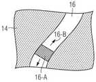
现在将基于用于钞票的防伪元件的例子来说明本发明。图1示出了具有本发明的光学可变防伪元件12的钞票10的示意图,该光学可变防伪元件12为粘合转移元件的形式。但是不言而喻,本发明不限于转移元件和钞票,而是可用于所有类型的防伪元件,例如用在货物和包装上或用于保护文件、身份证、护照、信用卡、医保卡等的标签。在钞票和类似的文件的情况下,除了转移元件(具有或不具有自己的载体层的贴片)之外,还可设想防伪线或防伪条等。The invention will now be explained based on the example of a security element for banknotes. Figure 1 shows a schematic view of a
图1所示的防伪元件12本身构造为非常平坦,但是仍然向观察者传达图案14的三维印象,该图案14明显从钞票10的平面凸出,并且该图案以第一颜色(例如蓝色)显现。图案14例如可表示数字、肖像或其它图形图案。在局部区域16中的蓝色图案14内,能看到第二种颜色的运动效果,例如在局部区域16中,当倾斜钞票10时,亮红色条看起来沿着该局部区域上下运动,产生所谓的滚动条效果。作为一个显著的特殊特征,不同颜色(红色或蓝色)和不同效果(三维图案或运动条)的区域以精确的相互配准的方式布置。因此,这种配准在下文中也称为颜色-效果配准。The
现在参照图2和3更详细地说明本发明的光学可变防伪元件的特殊结构,其中图2以横截面图示意性地示出了防伪元件12的细节,而图3为了展示视觉外观的目的示出了防伪元件12的细节的平面图。The particular structure of the optically variable security element of the present invention will now be explained in more detail with reference to Figures 2 and 3, wherein Figure 2 schematically shows the details of the
首先请参考图2的横截面图,防伪元件12包括平面载体18,该平面载体的平面扩展限定x-y平面和垂直于该平面的z轴。Referring first to the cross-sectional view of FIG. 2, the
在载体18上布置有多色反射平面区域20,并且该多色反射平面区域20包括在z方向上相对于平面载体20布置在两个特定的不同高度层的两个压印结构区域24、34。在此示例性实施例中,每个浮雕结构区域均代表微镜浮雕或微镜构造24、34,每个微镜浮雕或微镜构造都由相对于x-y平面倾斜的多个微镜形成。微镜的局部倾角在此精确地选择为使得微镜构造24、34的浮雕结构在油墨涂覆之后产生期望的光学外观,例如图案14的凸出三维效果或局部区域16的滚动条效果。不同的高度层由载体18上方的微镜构造24、34的基底区域的不同高度H1、H2给出。A polychromatic reflective
为了产生所需颜色效果的视觉对比,微镜构造24、34分别设有油墨涂层26、36,这些油墨涂层为观察者40产生微镜构造的不同颜色效果。在此示例性实施例中,下层的微镜构造24涂有红色上光油墨26,而上层的微镜构造34涂有蓝色上光油墨36。In order to create a visual contrast of desired color effects, the
微镜构造24、34分别被压印到透明压印漆层22、32中,并且在施加相应的油墨涂层26、36并可选地进行结构化之后,分别用透明面漆层28或38找平。面漆层具有与压印漆层22、32基本相同的折射率,从而没有油墨涂层的区域中的微镜不会因压印漆层与面漆层之间没有折射率差异而在视觉上显现出来。The
防伪元件12是针对从上方观察(或在反射中观察)而构造的,因而远离观察者40的微镜构造24称为布置在较低层的微镜构造,而靠近观察者40的微镜构造34称为布置在较高层的微镜构造。The
在此示例性实施例中,两个微镜构造24、34在防伪元件12的整个平面区域20中彼此叠置。在局部区域16中,布置在较高层34处的微镜构造的油墨涂层36具有大面积凹部42,例如为5毫米宽和2厘米长的弯曲条的形状。在凹部42的区域中,由于漆层32、38之间没有折射率差,因此微镜构造34的微镜不会产生光学效果,因而观察者40能透过这些漆层看到布置在较低层24的具有红色油墨涂层26的微镜构造。另一方面,在凹部42外,平面区域20的视觉效果由布置在较高层34的具有蓝色油墨涂层36的微镜构造决定。In this exemplary embodiment, the two
因此,如图3所示,观察者在凹部42外感知到由微镜构造34产生的蓝色图案14,而在凹部42内,在局部区域16中显现红色滚动条效果,其中当钞票10倾斜时,亮条16-A显现为沿箭头16-B的方向来回运动。两个微镜构造24、34的高度差在数微米或数十微米的范围内,因此观察者40察觉不到。因此,对于观察者40来说,两个不同颜色的图案和不同效果14、16看起来是精确配准地彼此并排布置的。对于观察者40来说,如图2中的由两条虚线所示,在凹部42的两侧实现了精确配准。Thus, as shown in FIG. 3 , the observer perceives the
图4示出了图2和3的配置的一种变化形式,其中布置在较高层34的微镜构造的油墨涂层36具有交替的条形凹部42和相同尺寸的条形剩余区域。在图4的实施例中,微镜构造24、34的微镜的局部倾角选择为使得每个微镜构造产生具有相反的运动方向的滚动条效果。在防伪元件倾斜时,观察者在保留了蓝色墨水涂层36的局部区域14中看到蓝色滚动条效果,并且在局部区域16的凹部中看到与其精确套准的红色滚动条效果。对于观察者来说,蓝色条14-A和红色条16-A分别沿相反方向运动,如图4所示。FIG. 4 shows a variation of the configuration of FIGS. 2 and 3 in which the
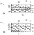
图5示出了本发明的防伪元件的一些有利的箔片结构。Figure 5 shows some advantageous foil structures of the security element of the invention.
在图5(a)的防伪元件50中,具有所需的微镜压印层24、34、油墨涂层26、36和透明面漆层28、38的透明压印漆层22、32布置在透明聚酯载体箔片18的两个相反侧面上。防伪元件50是针对从油墨涂层36的侧面观察而构造的,因而布置在较高层34的微镜构造的油墨涂层36设有大面积凹部42,观察者在该凹部中能看到布置在较低层24的具有油墨涂层26的微镜构造。In the
图5(b)的防伪元件52具有已经针对图2说明的层结构。两个微镜浮雕层24、34都布置在载体箔片18的同一侧,在此实施例中,该载体箔片18不一定必须是透明的。在载体箔片上,依次布置有带有布置在较低层24的第一微镜压印层的第一压印漆层22、第一油墨涂层26、第一透明面漆层28、带有布置在较高层34的第二微镜压印层的第二透明压印漆层32、第二油墨涂层36、以及第二透明面漆层38。防伪元件52是针对从油墨涂层36的侧面观察而构造的,因而布置在较高层34的微镜构造的油墨涂层36设有大面积凹部42,观察者在该凹部中能看到布置在较低层24的具有油墨涂层26的微镜构造。The
图5b的其它变化形式在附图中未单独示出。透明箔片也可布置在另外的层22、26、28和32、36、38之上。透明箔片可以是防伪元件的载体箔片18或另一个载体箔片,或者用作保护箔片。另外的层22、26、28和32、36、38的顺序可以不变。或者,第一压印漆层22可布置在第一面漆层28之上和/或第二压印漆层32可布置在第二面漆层38之上。例如,在布置在上方的透明箔片18下面,其它的层按照32、36、38、22、26、28的顺序布置。Other variants of Figure 5b are not shown separately in the figures. Transparent foils may also be arranged over the
不论载体箔片18处于哪个位置,从图5b开始,以下的变化形式是可能的。油墨涂层26和面漆层28和/或油墨涂层36和面漆层38可由具有上表面(尤其是平坦的上表面)的油墨涂层26或36形成。油墨涂层26和/或36包括在两个表面上遵循浮雕结构的反射局部层(例如金属化层)、以及在下表面上遵循浮雕结构的上光油墨局部层,而上光油墨局部层的上表面不遵循浮雕结构,优选构造为平面的。在另一个变化形式中,图5b中的下油墨涂层26的上彩色上光局部层形成下面漆层28,同时形成上压印漆层32。油墨涂层26优选又包括在两个表面上遵循浮雕结构的反射局部层(例如金属化层)。油墨涂层26的上光染色局部层(优选是压印漆层)的下表面遵循下浮雕结构24,并且其上表面遵循上浮雕结构34。在另一个变化形式中,下油墨涂层至少(或精确地)包括三个局部层:反射局部层、补偿局部层、以及带有上光油墨(优选是染色压印漆)的局部层。反射局部层的一个(或两个)表面遵循第二下浮雕结构24,而彩色上光局部层的上侧遵循第一上浮雕结构34。Regardless of the position of the
在其它配置中,两个箔片18-A、18-B也可用于防伪元件的制造,每个箔片分别设有微镜结构22-28或32-38之一,然后适当地层压在一起。In other configurations, two foils 18-A, 18-B can also be used in the manufacture of security elements, each foil being provided with one of the micromirror structures 22-28 or 32-38, respectively, and then suitably laminated together .
在图5(c)的防伪元件54中,两个载体箔片18-A、18-B层压在一起,使得微镜结构22-28和32-38布置在内侧。层压结构56可包括层压箔片,或者可仅由层压粘胶形成。在这种配置中,载体箔片18-A、18-B中的一个或两个可在层压后剥离,以使防伪元件54构造得尽可能薄。尤其是,在采用层压箔片时,甚至两个载体箔片18-A、18-B均可剥离,因为防伪元件54的稳定性由在此作为防伪元件的平面载体的层压箔片保证。防伪元件54也是针对从油墨涂层36的侧面观察而构造的,因而布置在较高层34的微镜构造的油墨涂层36设有大面积凹部42,观察者在该凹部中能看到布置在较低层24的具有油墨涂层26的微镜构造。In the
在图5(d)的防伪元件58中,载体箔片18-A、18-B层压在一起,使得一个微镜结构22-28布置在内侧,而另一个微镜结构32-38布置在外侧。层压结构56可包括层压箔片,或者可仅由层压粘胶形成。位于外侧的载体箔片18-A可在层压后剥离,以使防伪元件58构造得尽可能薄。大面积凹部42在此也设置在位于较高层34的微镜构造的油墨涂层36中,以使观察者能够看到布置在较低层24的具有油墨涂层26的微镜构造。In the
在附图中未示出的另一种变化形式最终是将载体箔片层压在一起,使得微镜结构22-28或32-38、42都布置在外侧。Another variant, not shown in the figures, is ultimately to laminate the carrier foils together so that the micromirror structures 22-28 or 32-38, 42 are all arranged on the outside.
在上文中已经更详细地说明,油墨涂层26、36不仅可由上光油墨形成,而且可由金属化层、薄膜结构、背衬有金属化层的上光油墨、具有金属镜面的发光油墨、结构油墨或纳米颗粒油墨等形成。As explained in more detail above, the
同样如上所述,载体箔片18是可选的元件。因此,在所示出、述及或随后的每个变化形式中可将其省略。例如,图5(b)中的载体箔片18、图5(c)中的载体箔片18-A/B或图5(d)中的载体箔片18-A可在将防伪元件施加到目标基材上之前(或之后)去除。在这种配置中设有布置在载体箔片与另外的层之间的分离层(未示出)。Also as described above, the
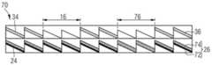
如图6和7所示,本发明的防伪元件还可包括带有阴文标记的区域,例如阴文文字。为了简化起见,在这些图中,仅示出了微镜构造22-28和32-38,而没有示出载体箔片或层结构的其它层。As shown in Figures 6 and 7, the security element of the present invention may also include regions bearing inscriptions in cymbal, such as text in cymbal. For simplicity, in these figures, only the micromirror configurations 22-28 and 32-38 are shown, and no other layers of the carrier foil or layer structure are shown.
图6的防伪元件60在结构上基本上与图2的防伪元件12类似,尤其是,布置在较高层34的微镜构造的油墨涂层36在局部区域16中包括凹部42,该凹部42布置在位于较低层24的微镜构造的涂层区域26上方,并产生上述的颜色-效果配准。此外,防伪元件60还具有局部区域62,在该局部区域中,两个微镜构造24、34的油墨涂层26、36是凹陷的(凹部44和42),从而防伪元件60在这些区域中不显现两个油墨涂层的任何颜色效果。The
局部区域62的形状形成在透射光中特别好辨认的阴文标记,尤其是阴文文字,而防伪元件的其它层至少是半透明构造的。在局部区域62中,布置在较低层24的微镜构造的油墨涂层26的凹部44的面积稍大于油墨涂层36中的相关凹部42的面积,以吸收两个压印结构24、34之间的套准波动。重叠布置的凹部42、44的线宽大于100微米,尤其是大于300微米,以确保阴文标记易辨认。The shape of the
还可设置彩色阴文标记,如图7的防伪元件70所示。在此示例性实施例中,布置在较低层24的微镜构造的油墨涂层26由背衬有金属化层72的上光油墨74组成。如图6所示,在局部区域16中,油墨涂层36的凹部42布置在位于较低层24的微镜构造的全涂层区域26上方,从而在这些局部区域中产生如上所述的颜色-效果配准。Colored negative indicia can also be provided, as shown in the
此外,防伪元件70包括局部区域76,在该局部区域中,除了布置在较高层34的微镜构造的油墨涂层36之外,布置在较低层24的微镜构造的油墨涂层26的金属化层72也是凹陷的,但是上光油墨74被保留。虽然防伪元件70在局部区域16中透过金属化层72显现为彩色且不透明的,但是由于在该处没有金属化层72,因此局部区域76是有色且半透明的。因此,局部区域76的形状形成在透射光中特别好辨认的彩色阴文标记,尤其是阴文文字,而防伪元件的其它层至少是半透明构造的。同样,在图7的示例性实施例中,金属化层72中的凹部最好构造为具有比油墨涂层36中的凹部42稍大的面积,以吸收套准波动。重叠布置的凹部的线宽也优选大于100微米,尤其是大于300微米,以确保彩色阴文标记易辨认。Furthermore, the
附图标记列表List of reference signs
10 钞票10 banknotes
12 防伪元件12 Anti-counterfeiting elements
14-A 凸出图案14-A Raised Pattern
16 局部区域16 Local area
16-A 亮条16-A Bright bar
16-B 运动方向16-B Direction of movement
18 载体18 carriers
18-A、18-B 载体箔片18-A, 18-B Carrier foil
20 反射平面区域20 Reflecting Plane Area
22 压印漆层22 Embossed Lacquer Layers
24 微镜构造24 Micromirror Construction
26 油墨涂层26 Ink coating
28 面漆层28 topcoat layers
32 压印漆层32 Embossed Lacquer Layers
34 微镜构造34 Micromirror Construction
36 油墨涂层36 Ink coating
38 面漆层38 topcoat layers
40 观察者40 Observers
42 大面积凹部42 Large-area recesses
44 凹部44 Recess
50、52、54 防伪元件50, 52, 54 Anti-counterfeiting elements
56 层压结构56 Laminated structure
58 防伪元件58 Anti-counterfeiting elements
60 防伪元件60 Security elements
62 带有阴文标记的局部区域62 Local area with engraved marking
70 防伪元件70 Anti-counterfeiting elements
72 金属化72 Metallization
74 上光油墨层74 Coating ink layer
Claims (23)
Applications Claiming Priority (3)
| Application Number | Priority Date | Filing Date | Title |
|---|---|---|---|
| DE102018005474.9ADE102018005474A1 (en) | 2018-07-09 | 2018-07-09 | Optically variable security element with reflective surface area |
| DE102018005474.9 | 2018-07-09 | ||
| PCT/EP2019/000209WO2020011391A1 (en) | 2018-07-09 | 2019-07-09 | Optically variable security element having reflective surface region |
Publications (2)
| Publication Number | Publication Date |
|---|---|
| CN112166041A CN112166041A (en) | 2021-01-01 |
| CN112166041Btrue CN112166041B (en) | 2022-09-27 |
Family
ID=67383717
Family Applications (1)
| Application Number | Title | Priority Date | Filing Date |
|---|---|---|---|
| CN201980035864.8AActiveCN112166041B (en) | 2018-07-09 | 2019-07-09 | Optically variable security element with reflective surface area |
Country Status (5)
| Country | Link |
|---|---|
| US (1) | US11654709B2 (en) |
| EP (1) | EP3820714B1 (en) |
| CN (1) | CN112166041B (en) |
| DE (1) | DE102018005474A1 (en) |
| WO (1) | WO2020011391A1 (en) |
Families Citing this family (19)
| Publication number | Priority date | Publication date | Assignee | Title |
|---|---|---|---|---|
| DE102018005474A1 (en) | 2018-07-09 | 2020-01-09 | Giesecke+Devrient Currency Technology Gmbh | Optically variable security element with reflective surface area |
| DE102019004325A1 (en) | 2019-06-18 | 2020-12-24 | Giesecke+Devrient Currency Technology Gmbh | Security substrate and document of value produced therefrom |
| WO2021205366A1 (en)* | 2020-04-07 | 2021-10-14 | Entrust Corporation | Laser textured identification document surfaces |
| DE102020004091A1 (en)* | 2020-07-07 | 2022-01-13 | Giesecke+Devrient Currency Technology Gmbh | Optically variable security element |
| DE102020004959A1 (en) | 2020-08-13 | 2022-02-17 | Giesecke+Devrient Currency Technology Gmbh | Optically variable security element |
| DE102020005522A1 (en) | 2020-09-09 | 2022-03-10 | Giesecke+Devrient Currency Technology Gmbh | Optically variable security element |
| DE102020005912A1 (en) | 2020-09-28 | 2022-03-31 | Giesecke+Devrient Currency Technology Gmbh | Process for producing an optically variable security element |
| DE102020005932A1 (en) | 2020-09-28 | 2022-03-31 | Giesecke+Devrient Currency Technology Gmbh | Optically variable security element with reflective surface area |
| DE102020006902A1 (en) | 2020-11-10 | 2022-05-12 | Giesecke+Devrient Currency Technology Gmbh | Optically variable security element and method for producing an optically variable security element |
| DE102020007013A1 (en) | 2020-11-16 | 2022-05-19 | Giesecke+Devrient Currency Technology Gmbh | Optically variable security element with reflective/transmissive feature area |
| CN114905881B (en)* | 2021-02-10 | 2023-08-22 | 中钞特种防伪科技有限公司 | Security element, method for producing the same, and security product |
| DE102021001589A1 (en) | 2021-03-25 | 2022-09-29 | Giesecke+Devrient Currency Technology Gmbh | Manufacturing process for an optically variable security element |
| DE102021001588A1 (en)* | 2021-03-25 | 2022-09-29 | Giesecke+Devrient Currency Technology Gmbh | Manufacturing process for an optically variable security element |
| DE102021001582A1 (en) | 2021-03-25 | 2022-09-29 | Giesecke+Devrient Currency Technology Gmbh | Optically variable security element, manufacturing process and embossing arrangement |
| DE102021001898A1 (en) | 2021-04-13 | 2022-10-13 | Giesecke+Devrient Currency Technology Gmbh | OPTICALLY VARIABLE SECURITY ELEMENT AND VALUABLE DOCUMENT WITH THE OPTICALLY VARIABLE SECURITY ELEMENT |
| CN115230364B (en)* | 2021-04-25 | 2024-03-29 | 中钞特种防伪科技有限公司 | Optical security element, method for designing an optical security element, security product and data carrier |
| DE102021002599A1 (en) | 2021-05-18 | 2022-11-24 | Giesecke+Devrient Currency Technology Gmbh | Optically variable display element |
| DE102023125600A1 (en)* | 2023-09-21 | 2025-03-27 | Giesecke+Devrient Currency Technology Gmbh | Method for producing a security element with a relief structure and security element with a relief structure |
| DE102024109646A1 (en)* | 2024-04-05 | 2025-10-09 | Giesecke+Devrient Currency Technology Gmbh | Optically variable display element |
Family Cites Families (17)
| Publication number | Priority date | Publication date | Assignee | Title |
|---|---|---|---|---|
| ATE357345T1 (en)* | 1995-11-28 | 2007-04-15 | Ovd Kinegram Ag | OPTICAL INFORMATION CARRIER |
| US6060143A (en)* | 1996-11-14 | 2000-05-09 | Ovd Kinegram Ag | Optical information carrier |
| GB0504959D0 (en) | 2005-03-10 | 2005-04-20 | Rue International De La Ltd | Security device based on customised microprism film |
| DE102005061749A1 (en)* | 2005-12-21 | 2007-07-05 | Giesecke & Devrient Gmbh | Optically variable security element for making valuable objects safe has an achromatic reflecting micro-structure taking the form of a mosaic made from achromatic reflecting mosaic elements |
| DE102007005884B4 (en)* | 2007-02-07 | 2022-02-03 | Leonhard Kurz Stiftung & Co. Kg | security document |
| DE102007039996B4 (en)* | 2007-02-07 | 2020-09-24 | Leonhard Kurz Stiftung & Co. Kg | Security element for a security document and method for its production |
| WO2008146422A1 (en)* | 2007-05-25 | 2008-12-04 | Toppan Printing Co., Ltd. | Indicator and information printed matter |
| DE102007061827A1 (en)* | 2007-12-20 | 2009-06-25 | Giesecke & Devrient Gmbh | Security element and method for its production |
| DE102008009296A1 (en) | 2008-02-15 | 2009-08-20 | Giesecke & Devrient Gmbh | Security element and method for its production |
| DE102008017652A1 (en)* | 2008-04-04 | 2009-10-08 | Leonhard Kurz Stiftung & Co. Kg | Security element and method for producing a security element |
| DE102010047250A1 (en) | 2009-12-04 | 2011-06-09 | Giesecke & Devrient Gmbh | Security element, value document with such a security element and manufacturing method of a security element |
| DE102010025775A1 (en)* | 2010-07-01 | 2012-01-05 | Giesecke & Devrient Gmbh | Security element and value document with such a security element |
| JP5659820B2 (en) | 2011-01-24 | 2015-01-28 | 大日本印刷株式会社 | Hologram sheet |
| DE102013005937A1 (en) | 2013-04-05 | 2014-10-09 | Giesecke & Devrient Gmbh | Method for producing a security element with negative writing |
| US10281626B2 (en)* | 2015-07-25 | 2019-05-07 | NanoMedia Solutions Inc. | Color image display devices comprising structural color pixels that are selectively activated and/or deactivated by material deposition |
| DE102015010945A1 (en) | 2015-08-19 | 2017-02-23 | Giesecke & Devrient Gmbh | value document |
| DE102018005474A1 (en) | 2018-07-09 | 2020-01-09 | Giesecke+Devrient Currency Technology Gmbh | Optically variable security element with reflective surface area |
- 2018
- 2018-07-09DEDE102018005474.9Apatent/DE102018005474A1/ennot_activeWithdrawn
- 2019
- 2019-07-09WOPCT/EP2019/000209patent/WO2020011391A1/ennot_activeCeased
- 2019-07-09CNCN201980035864.8Apatent/CN112166041B/enactiveActive
- 2019-07-09USUS17/258,719patent/US11654709B2/enactiveActive
- 2019-07-09EPEP19742126.6Apatent/EP3820714B1/enactiveActive
Also Published As
| Publication number | Publication date |
|---|---|
| US20210283939A1 (en) | 2021-09-16 |
| EP3820714B1 (en) | 2023-07-19 |
| US11654709B2 (en) | 2023-05-23 |
| CN112166041A (en) | 2021-01-01 |
| WO2020011391A1 (en) | 2020-01-16 |
| EP3820714A1 (en) | 2021-05-19 |
| DE102018005474A1 (en) | 2020-01-09 |
Similar Documents
| Publication | Publication Date | Title |
|---|---|---|
| CN112166041B (en) | Optically variable security element with reflective surface area | |
| CN112118965B (en) | Optically variable security element with reflective surface area | |
| US9176266B2 (en) | Security element, value document comprising such a security element and method for producing such a security element | |
| US11807029B2 (en) | Method for producing an optically variable security element | |
| US9902187B2 (en) | Security devices and methods of manufacture thereof | |
| US9724955B2 (en) | Security devices and methods of manufacture thereof | |
| CN115066338B (en) | Optically variable security elements | |
| EP3445592B1 (en) | Security devices and methods of manufacture thereof | |
| CN106573488B (en) | Visually variable security elements | |
| US20170313121A1 (en) | Multi-Layer Body and Method for Producing Same | |
| WO2017068769A1 (en) | Display body, display body-equipped article, and display body observation method | |
| AU2014250641A1 (en) | Security element, value document comprising such a security element and method for producing such a security element | |
| CN109154792B (en) | Method for producing a volume holographic film with a security element formed as a transfer section | |
| CN115835966A (en) | Optically variable security element | |
| CN113950414A (en) | Optically variable security element | |
| WO2018172764A1 (en) | Methods of manufacturing security devices and image arrays therefor | |
| US12128702B2 (en) | Method for producing a security element comprising micro-imaging elements | |
| CN116075435B (en) | Optically variable security elements | |
| JP2020519478A (en) | Security element and manufacturing method thereof | |
| AU2016228200A1 (en) | Security element, value document comprising such a security element and method for producing such a security element | |
| HK1243978B (en) | Security element with effect pigments and an embossing structure and method for the production thereof |
Legal Events
| Date | Code | Title | Description |
|---|---|---|---|
| PB01 | Publication | ||
| PB01 | Publication | ||
| SE01 | Entry into force of request for substantive examination | ||
| SE01 | Entry into force of request for substantive examination | ||
| GR01 | Patent grant | ||
| GR01 | Patent grant |