CN112165961A - Negative pressure pump and related methods - Google Patents
Negative pressure pump and related methodsDownload PDFInfo
- Publication number
- CN112165961A CN112165961ACN201980034693.7ACN201980034693ACN112165961ACN 112165961 ACN112165961 ACN 112165961ACN 201980034693 ACN201980034693 ACN 201980034693ACN 112165961 ACN112165961 ACN 112165961A
- Authority
- CN
- China
- Prior art keywords
- reservoir
- spring
- plunger
- negative pressure
- drive assembly
- Prior art date
- Legal status (The legal status is an assumption and is not a legal conclusion. Google has not performed a legal analysis and makes no representation as to the accuracy of the status listed.)
- Pending
Links
- 238000000034methodMethods0.000titleclaimsabstractdescription32
- 210000001124body fluidAnatomy0.000claimsabstractdescription47
- 238000004519manufacturing processMethods0.000claimsdescription13
- 238000004804windingMethods0.000claimsdescription7
- 238000004891communicationMethods0.000claimsdescription5
- 238000007789sealingMethods0.000claimsdescription2
- 230000003213activating effectEffects0.000claims1
- 230000007246mechanismEffects0.000description55
- 206010052428WoundDiseases0.000description16
- 208000027418Wounds and injuryDiseases0.000description16
- 238000003860storageMethods0.000description15
- 230000004913activationEffects0.000description13
- 239000000463materialSubstances0.000description12
- 239000010839body fluidSubstances0.000description10
- 239000012530fluidSubstances0.000description9
- 239000000203mixtureSubstances0.000description8
- 239000004033plasticSubstances0.000description8
- 229920003023plasticPolymers0.000description8
- 229920001971elastomerPolymers0.000description7
- -1but not limited toSubstances0.000description6
- 239000002184metalSubstances0.000description6
- 229910052751metalInorganic materials0.000description6
- 239000005060rubberSubstances0.000description6
- 230000008901benefitEffects0.000description5
- 230000000994depressogenic effectEffects0.000description5
- 239000011521glassSubstances0.000description5
- 229920001296polysiloxanePolymers0.000description5
- 239000000853adhesiveSubstances0.000description4
- 230000001070adhesive effectEffects0.000description4
- VLKZOEOYAKHREP-UHFFFAOYSA-Nn-HexaneChemical compoundCCCCCCVLKZOEOYAKHREP-UHFFFAOYSA-N0.000description4
- 238000000576coating methodMethods0.000description3
- 230000007423decreaseEffects0.000description3
- 230000000881depressing effectEffects0.000description3
- 230000035876healingEffects0.000description3
- 230000008569processEffects0.000description3
- 238000012546transferMethods0.000description3
- 239000011248coating agentSubstances0.000description2
- 208000014674injuryDiseases0.000description2
- 230000003993interactionEffects0.000description2
- 239000007788liquidSubstances0.000description2
- 238000012986modificationMethods0.000description2
- 230000004048modificationEffects0.000description2
- IJDNQMDRQITEOD-UHFFFAOYSA-Nn-butaneChemical compoundCCCCIJDNQMDRQITEOD-UHFFFAOYSA-N0.000description2
- 239000007787solidSubstances0.000description2
- 238000001356surgical procedureMethods0.000description2
- 230000008733traumaEffects0.000description2
- 238000009825accumulationMethods0.000description1
- 230000009471actionEffects0.000description1
- 239000000956alloySubstances0.000description1
- 229910045601alloyInorganic materials0.000description1
- 230000000712assemblyEffects0.000description1
- 238000000429assemblyMethods0.000description1
- 230000004888barrier functionEffects0.000description1
- 230000000903blocking effectEffects0.000description1
- 230000008859changeEffects0.000description1
- 238000004140cleaningMethods0.000description1
- 239000004020conductorSubstances0.000description1
- 230000008878couplingEffects0.000description1
- 238000010168coupling processMethods0.000description1
- 238000005859coupling reactionMethods0.000description1
- 239000000806elastomerSubstances0.000description1
- 229920001746electroactive polymerPolymers0.000description1
- 239000003292glueSubstances0.000description1
- 238000005304joiningMethods0.000description1
- 230000013011matingEffects0.000description1
- 150000002739metalsChemical class0.000description1
- 238000003825pressingMethods0.000description1
- 238000011084recoveryMethods0.000description1
- 238000011160researchMethods0.000description1
- 230000000284resting effectEffects0.000description1
- 238000000926separation methodMethods0.000description1
- 238000012800visualizationMethods0.000description1
Images


Classifications
- A—HUMAN NECESSITIES
- A61—MEDICAL OR VETERINARY SCIENCE; HYGIENE
- A61M—DEVICES FOR INTRODUCING MEDIA INTO, OR ONTO, THE BODY; DEVICES FOR TRANSDUCING BODY MEDIA OR FOR TAKING MEDIA FROM THE BODY; DEVICES FOR PRODUCING OR ENDING SLEEP OR STUPOR
- A61M1/00—Suction or pumping devices for medical purposes; Devices for carrying-off, for treatment of, or for carrying-over, body-liquids; Drainage systems
- A61M1/64—Containers with integrated suction means
- A61M1/67—Containers incorporating a piston-type member to create suction, e.g. syringes
- A—HUMAN NECESSITIES
- A61—MEDICAL OR VETERINARY SCIENCE; HYGIENE
- A61F—FILTERS IMPLANTABLE INTO BLOOD VESSELS; PROSTHESES; DEVICES PROVIDING PATENCY TO, OR PREVENTING COLLAPSING OF, TUBULAR STRUCTURES OF THE BODY, e.g. STENTS; ORTHOPAEDIC, NURSING OR CONTRACEPTIVE DEVICES; FOMENTATION; TREATMENT OR PROTECTION OF EYES OR EARS; BANDAGES, DRESSINGS OR ABSORBENT PADS; FIRST-AID KITS
- A61F13/00—Bandages or dressings; Absorbent pads
- A61F13/05—Bandages or dressings; Absorbent pads specially adapted for use with sub-pressure or over-pressure therapy, wound drainage or wound irrigation, e.g. for use with negative-pressure wound therapy [NPWT]
- A—HUMAN NECESSITIES
- A61—MEDICAL OR VETERINARY SCIENCE; HYGIENE
- A61M—DEVICES FOR INTRODUCING MEDIA INTO, OR ONTO, THE BODY; DEVICES FOR TRANSDUCING BODY MEDIA OR FOR TAKING MEDIA FROM THE BODY; DEVICES FOR PRODUCING OR ENDING SLEEP OR STUPOR
- A61M1/00—Suction or pumping devices for medical purposes; Devices for carrying-off, for treatment of, or for carrying-over, body-liquids; Drainage systems
- A61M1/71—Suction drainage systems
- A61M1/76—Handpieces
- A—HUMAN NECESSITIES
- A61—MEDICAL OR VETERINARY SCIENCE; HYGIENE
- A61M—DEVICES FOR INTRODUCING MEDIA INTO, OR ONTO, THE BODY; DEVICES FOR TRANSDUCING BODY MEDIA OR FOR TAKING MEDIA FROM THE BODY; DEVICES FOR PRODUCING OR ENDING SLEEP OR STUPOR
- A61M1/00—Suction or pumping devices for medical purposes; Devices for carrying-off, for treatment of, or for carrying-over, body-liquids; Drainage systems
- A61M1/80—Suction pumps
- A61M1/81—Piston pumps, e.g. syringes
- A61M1/815—Piston pumps, e.g. syringes the barrel serving as aspiration container, e.g. in a breast pump
- A—HUMAN NECESSITIES
- A61—MEDICAL OR VETERINARY SCIENCE; HYGIENE
- A61M—DEVICES FOR INTRODUCING MEDIA INTO, OR ONTO, THE BODY; DEVICES FOR TRANSDUCING BODY MEDIA OR FOR TAKING MEDIA FROM THE BODY; DEVICES FOR PRODUCING OR ENDING SLEEP OR STUPOR
- A61M1/00—Suction or pumping devices for medical purposes; Devices for carrying-off, for treatment of, or for carrying-over, body-liquids; Drainage systems
- A61M1/90—Negative pressure wound therapy devices, i.e. devices for applying suction to a wound to promote healing, e.g. including a vacuum dressing
- A61M1/96—Suction control thereof
- A61M1/962—Suction control thereof having pumping means on the suction site, e.g. miniature pump on dressing or dressing capable of exerting suction
- A—HUMAN NECESSITIES
- A61—MEDICAL OR VETERINARY SCIENCE; HYGIENE
- A61M—DEVICES FOR INTRODUCING MEDIA INTO, OR ONTO, THE BODY; DEVICES FOR TRANSDUCING BODY MEDIA OR FOR TAKING MEDIA FROM THE BODY; DEVICES FOR PRODUCING OR ENDING SLEEP OR STUPOR
- A61M1/00—Suction or pumping devices for medical purposes; Devices for carrying-off, for treatment of, or for carrying-over, body-liquids; Drainage systems
- A61M1/71—Suction drainage systems
- A61M1/74—Suction control
- A61M1/741—Suction control with means for varying suction manually
- A—HUMAN NECESSITIES
- A61—MEDICAL OR VETERINARY SCIENCE; HYGIENE
- A61M—DEVICES FOR INTRODUCING MEDIA INTO, OR ONTO, THE BODY; DEVICES FOR TRANSDUCING BODY MEDIA OR FOR TAKING MEDIA FROM THE BODY; DEVICES FOR PRODUCING OR ENDING SLEEP OR STUPOR
- A61M2205/00—General characteristics of the apparatus
- A61M2205/10—General characteristics of the apparatus with powered movement mechanisms
- A61M2205/103—General characteristics of the apparatus with powered movement mechanisms rotating
Landscapes
- Health & Medical Sciences (AREA)
- Heart & Thoracic Surgery (AREA)
- General Health & Medical Sciences (AREA)
- Engineering & Computer Science (AREA)
- Biomedical Technology (AREA)
- Life Sciences & Earth Sciences (AREA)
- Animal Behavior & Ethology (AREA)
- Vascular Medicine (AREA)
- Public Health (AREA)
- Veterinary Medicine (AREA)
- Anesthesiology (AREA)
- Hematology (AREA)
- Infusion, Injection, And Reservoir Apparatuses (AREA)
- Media Introduction/Drainage Providing Device (AREA)
Abstract
Description
Translated fromChinese相关申请的交叉引用CROSS-REFERENCE TO RELATED APPLICATIONS
依照美国法典第35章第119条,本专利申请要求于2018年4月2日提交的美国临时专利申请第62/651,407号和于2019年3月20日提交的美国临时专利申请第62/820,912号的权益,这些临时专利申请的全部内容以参考的方式并入本文中。This patent application claims U.S. Provisional Patent Application No. 62/651,407, filed April 2, 2018, and U.S. Provisional Patent Application No. 62/820,912, filed March 20, 2019, pursuant to 35 U.S.C. § 119 The entire contents of these provisional patent applications are incorporated herein by reference.
技术领域technical field
本公开涉及一种负压泵。该负压泵可用于内部创伤或外部创伤或者用于其他医疗应用和/或非医疗应用。The present disclosure relates to a negative pressure pump. The negative pressure pump can be used for internal or external trauma or for other medical and/or non-medical applications.
背景技术Background technique
会发生可排除不受欢迎的体液聚集的情况。例如,在医疗手术中,在手术之前、之后或期间,体液会在患者的治疗部位汇集。体液的排除可加速愈合(例如在治疗部位),或者促进患者的康复。因此,对于以有效、低成本的方式从治疗部位吸出体液的装置和方法存在着需求。Circumstances can occur that preclude undesired accumulation of bodily fluids. For example, in medical surgery, body fluids can pool at the patient's treatment site before, after, or during surgery. Removal of bodily fluids may accelerate healing (eg, at the treatment site), or facilitate the recovery of the patient. Accordingly, there exists a need for devices and methods for aspirating bodily fluids from a treatment site in an efficient, low-cost manner.
发明内容SUMMARY OF THE INVENTION
本公开的一些实施方案旨在提供一种一次性负压泵;该负压泵包括贮室,其包括沿贮室的纵向轴线而限定腔体的内壁、联接到贮室的驱动组件(该驱动组件包括弹簧、形成抵接贮室内壁的密封且可在腔体内部沿纵向轴线滑动的柱塞);和延伸经过腔体的线缆,该线缆具有联接到驱动组件的第一端和联接到柱塞的第二端,其中利用驱动组件使柱塞沿贮室滑动在腔体内部产生负压。贮室可沿贮室的全长具有恒定的截面尺寸并且线缆可在线缆附接点联接到驱动组件。此外,驱动组件可包括第一鼓和第二鼓,其中线缆附接点可在第二鼓上。弹簧可联接到第二鼓,或者联接到第一鼓和第二鼓的每个鼓。在至少一个实施方案中,将弹簧卷绕于第一鼓上可导致线缆卷绕于第二鼓上,并且将线缆卷绕于第二鼓上可使柱塞沿贮室的纵向轴线移动。用于从靶部位排除体液的医疗系统可包括患者治疗单元,该患者治疗单元包括分流管和上述负压泵。Some embodiments of the present disclosure aim to provide a disposable negative pressure pump; the negative pressure pump comprising a reservoir including an inner wall defining a cavity along a longitudinal axis of the reservoir, a drive assembly (the drive assembly) coupled to the reservoir The assembly includes a spring, a plunger forming a seal against the inner wall of the reservoir and slidable along a longitudinal axis inside the cavity); and a cable extending through the cavity, the cable having a first end coupled to the drive assembly and a coupling to the second end of the plunger, wherein the plunger is slid along the reservoir chamber with a drive assembly to create a negative pressure inside the cavity. The reservoir may have a constant cross-sectional dimension along the entire length of the reservoir and the cable may be coupled to the drive assembly at the cable attachment point. Additionally, the drive assembly may include a first drum and a second drum, wherein the cable attachment point may be on the second drum. The spring may be coupled to the second drum, or to each of the first and second drums. In at least one embodiment, winding the spring on the first drum can cause the cable to be wound on the second drum, and winding the cable on the second drum can cause the plunger to move along the longitudinal axis of the reservoir . A medical system for removing bodily fluids from a target site may include a patient treatment unit including a shunt and the negative pressure pump described above.
本公开的各实施方案还旨在提供一种从靶部位排除体液的方法。该方法包括:将分流管的第一端放置在靶部位,其中分流管的第二端联接到负压泵,该负压泵包括:贮室,其包括沿贮室的纵向轴线限定腔体的内壁,分流管与贮室连通;联接到贮室且包括弹簧的驱动组件;和联接到驱动组件的柱塞,该柱塞具有与贮室的截面尺寸相对应的截面尺寸;以及启动负压泵的驱动组件,其中弹簧的运动使柱塞在腔体的内部移动以在贮室内部产生负压。靶部位可以是内部创伤、外部创伤、在患者上的任意位置、或与患者相关的任意位置。在患者上的位置可包括在患者身体内部的位置、在患者皮肤上的位置、患者治疗部位(其可未必是创伤)、手术部位等。与患者相关的位置可包括使在患者治疗、手术部位、临床研究部位等中所使用的器械或装置。弹簧可由扭转弹簧组成。Embodiments of the present disclosure also aim to provide a method of removing bodily fluids from a target site. The method includes placing a first end of the shunt tube at the target site, wherein the second end of the shunt tube is coupled to a negative pressure pump, the negative pressure pump including a reservoir including a cavity along a longitudinal axis of the reservoir defining a cavity an inner wall, a shunt in communication with the reservoir; a drive assembly coupled to the reservoir and including a spring; and a plunger coupled to the drive assembly, the plunger having a cross-sectional dimension corresponding to the cross-sectional dimension of the reservoir; and actuating the negative pressure pump The drive assembly in which the movement of the spring moves the plunger inside the cavity to create a negative pressure inside the reservoir. The target site may be an internal wound, an external wound, any location on the patient, or any location in relation to the patient. A location on a patient may include a location inside the patient's body, a location on the patient's skin, a patient treatment site (which may not necessarily be a wound), a surgical site, and the like. A patient-related location may include instruments or devices used in patient treatment, surgical sites, clinical research sites, and the like. The spring may consist of a torsion spring.
柱塞可在启动驱动组件之前沿贮室的纵向轴线与驱动组件间隔,并且在启动驱动组件之后柱塞可与驱动组件相邻。在至少一个实施方案中,驱动组件可经由沿纵向轴线延伸的线缆而联接到柱塞,并且驱动组件可进一步包括第一鼓和第二鼓。线缆可联接到第二鼓,并且当驱动组件被启动时弹簧可与第一鼓和第二鼓的每个鼓接合。The plunger may be spaced from the drive assembly along the longitudinal axis of the reservoir prior to actuation of the drive assembly, and the plunger may be adjacent to the drive assembly after actuation of the drive assembly. In at least one embodiment, the drive assembly can be coupled to the plunger via a cable extending along the longitudinal axis, and the drive assembly can further include a first drum and a second drum. The cable can be coupled to the second drum, and the spring can engage with each of the first and second drums when the drive assembly is activated.
本公开的各实施方案还包括一种制造负压泵的方法,该方法包括:使驱动组件的弹簧偏置以将其从第一鼓卷绕至第二鼓,其中负压泵的贮室包括限定沿贮室纵向轴线的腔体的内壁,驱动组件联接到贮室,并且其中驱动组件经由延伸经过贮室的腔体的线缆而联接到柱塞。偏置可包括将弹簧卷绕于第二鼓上并将弹簧锁定至偏置位置。可替换地或另外,偏置可包括经由齿轮进入孔而进入驱动组件的弹簧卷绕齿轮,及可能地在使弹簧偏置之后将齿轮进入孔加以密封。Embodiments of the present disclosure also include a method of making a negative pressure pump, the method comprising: biasing a spring of a drive assembly to wind it from a first drum to a second drum, wherein the reservoir of the negative pressure pump includes An inner wall defining the cavity along the longitudinal axis of the reservoir, the drive assembly is coupled to the reservoir, and wherein the drive assembly is coupled to the plunger via a cable extending through the cavity of the reservoir. Biasing may include wrapping the spring on the second drum and locking the spring in the biased position. Alternatively or additionally, the biasing may include entering the spring wrap gear of the drive assembly via the gear access hole, and possibly sealing the gear access hole after biasing the spring.
附图说明Description of drawings
并入本说明书中且构成本说明书的一部分的附图图解说明说明了各种示例性实施方案,并且连同描述用来解释本公开的原理。这些附图示出了本公开的不同方面,并且在适当的情况下在不同附图中说明类似结构、部件、材料和/或元件的附图标记则类似地进行标注。可以理解的是,除了具体示出以外的结构、部件、和/或元件的各种组合和/或省略是可想到的,并且是在本公开的范围内。The accompanying drawings, which are incorporated in and constitute a part of this specification, illustrate various exemplary embodiments and together with the description serve to explain the principles of the disclosure. The drawings illustrate different aspects of the present disclosure, and where appropriate, reference numerals describing similar structures, components, materials, and/or elements in the different drawings have been labeled similarly. It is to be understood that various combinations and/or omissions of structures, components, and/or elements other than those specifically shown are conceivable and are within the scope of the present disclosure.
存在着在本文中进行描述且在本文中进行说明的许多发明。所描述的发明并不局限于任何单个方面或者其实施方案,也不局限于上述方面和/或实施方案的任意组合和/或排列。此外,所描述发明的每个方面和/或其实施方案可单独地或者连同所描述发明和/或其实施方案的一个或多个其他方面而应用。为了简洁起见,本文中对某些排列和组合未进行论述并且/或者单独地进行说明。特别地,本文中被描述为“示例性”的实施方案或实施例不应被理解为优选的或有利的,例如相较于其他实施方案或实施例;相反,其意图是反映或表示该实施方案是“示范性”的实施方案。There are many inventions described and illustrated herein. The described invention is not limited to any single aspect or embodiment thereof, nor to any combination and/or permutation of the foregoing aspects and/or embodiments. Furthermore, each aspect of the described invention and/or its embodiments may be applied alone or in conjunction with one or more other aspects of the described invention and/or its embodiments. For the sake of brevity, certain permutations and combinations are not discussed herein and/or are individually described. In particular, an embodiment or example described herein as "exemplary" should not be construed as preferred or advantageous, such as over other embodiments or examples; rather, it is intended to reflect or represent that implementation Scenarios are "exemplary" implementations.
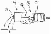
图1提供了根据本公开一个实施方案的示例性负压泵的可重复使用驱动单元和一次性贮室的分解视图。1 provides an exploded view of a reusable drive unit and disposable reservoir of an exemplary negative pressure pump according to one embodiment of the present disclosure.
图2A-图2D提供了根据本公开一个实施方案的图1的可重复使用驱动单元的机械驱动机构的各种视图。2A-2D provide various views of the mechanical drive mechanism of the reusable drive unit of FIG. 1 according to one embodiment of the present disclosure.
图3A-图3C提供了根据本公开一个实施方案的可将可重复使用驱动单元紧固到一次性贮室的示例性锁定机构的各种视图。3A-3C provide various views of an exemplary locking mechanism that can secure a reusable drive unit to a disposable reservoir, according to one embodiment of the present disclosure.
图4A-图4G提供了根据本公开一个实施方案的使用由可重复使用驱动单元和一次性贮室所组成的示例性负压泵的示例性方法。4A-4G provide an exemplary method of using an exemplary negative pressure pump composed of a reusable drive unit and a disposable reservoir, according to one embodiment of the present disclosure.
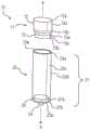
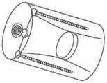
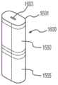
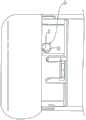
图5提供了根据公开第二实施方案的示例性一次性负压泵的视图。5 provides a view of an exemplary disposable negative pressure pump according to a second embodiment of the disclosure.
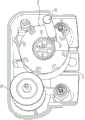
图6A-图6C提供了根据本公开第二实施方案的一次性负压泵的机械驱动组件的各种视图。6A-6C provide various views of a mechanical drive assembly of a disposable negative pressure pump according to a second embodiment of the present disclosure.
图7A-图7C描绘了根据本公开第二实施方案的驱动组件的示例性操作。7A-7C depict exemplary operation of a drive assembly according to a second embodiment of the present disclosure.
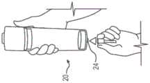
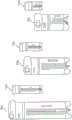
图8A-图8D提供了根据本公开一个实施方案的使用一次性负压泵的示例性方法。8A-8D provide an exemplary method of using a disposable negative pressure pump according to one embodiment of the present disclosure.
图9A-图9B、图10A-图10C、图11A-图11B和图12示出了根据本公开实施方案的负压泵的驱动组件的各种替代实施方案。9A-9B, 10A-10C, 11A-11B, and 12 illustrate various alternative embodiments of drive assemblies for negative pressure pumps according to embodiments of the present disclosure.
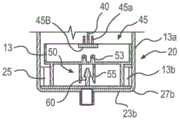
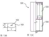
图13A-图13F提供了根据本公开一个实施方案的示例性压力致动负压泵的各种视图。13A-13F provide various views of an exemplary pressure-actuated negative pressure pump according to one embodiment of the present disclosure.
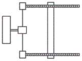
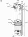
图14A和图14B提供了根据本公开一个实施方案的示例性恒转矩弹簧驱动负压泵的剖面透视图。14A and 14B provide cutaway perspective views of an exemplary constant torque spring driven negative pressure pump according to one embodiment of the present disclosure.
图14C和图4D提供了根据本公开一个实施方案的图14A和图14B的负压泵的示例性驱动组件的分解视图。14C and 4D provide exploded views of an exemplary drive assembly of the negative pressure pump of FIGS. 14A and 14B according to one embodiment of the present disclosure.
图14E和图14F提供了根据本公开一个实施方案的图14A和图14B的负压泵的示例性驱动组件锁具的视图。14E and 14F provide views of an exemplary drive assembly lock for the negative pressure pump of FIGS. 14A and 14B according to one embodiment of the present disclosure.
图14G-图14I提供了根据本公开一个实施方案的用于给图14A和图14B的负压泵的各自恒转矩弹簧进行赋能的示例性机构的视图。14G-14I provide views of an exemplary mechanism for energizing the respective constant torque springs of the negative pressure pump of FIGS. 14A and 14B according to one embodiment of the present disclosure.
图14J提供了根据本公开实施方案的图14A和图14B的各种尺寸的恒转矩弹簧驱动负压泵的视图。14J provides views of the various sized constant torque spring driven negative pressure pumps of FIGS. 14A and 14B in accordance with embodiments of the present disclosure.
本文中使用的术语“包括(comprise)”、“包括(comprising)”、“包含(include)”、“包含(including)”或它们的任何其他变型意图涵盖非排他性包含,因而包括一系列元件的过程、方法、物件、或器械不仅包含这些元件,而且可包含未明确列出的或者这种过程、方法、物件、或器械所特有的其他元件。术语“示例性”是在“示范性”而不是“理想”的意义上而使用。另外,本文中的术语“第一”、“第二”等不表示任何顺序、数量、或重要性,但相反是用于将一个元件或结构与另一个元件或结构加以区别。此外,本文中的术语“一”和“一种”并不表示对数量的限制,相反表示一个或多个引用物件的存在。The terms "comprise", "comprising", "include", "including" or any other variation thereof as used herein are intended to encompass a non-exclusive inclusion, thus including a list of elements A process, method, article, or instrument includes not only these elements, but may include other elements not expressly listed or specific to such a process, method, article, or instrument. The term "exemplary" is used in the sense of "exemplary" rather than "ideal". In addition, the terms "first," "second," etc. herein do not denote any order, quantity, or importance, but rather are used to distinguish one element or structure from another. Furthermore, the terms "a" and "an" herein do not denote a limitation of quantity, but rather denote the presence of one or more of the referenced item.
具体实施方式Detailed ways
本公开的实施方案涉及一种泵(例如负压泵),该泵可用于从靶部位排除体液。该泵可包括驱动机构和贮室。在使用中,管道分流管可连接到贮室并且该泵可用于在靶部位提供负压以促进愈合。例如,医学专业人员可使用该泵从患者中排除体液,例如以促进愈合。驱动机构可在贮室中形成负压室,从而将体液吸入贮室中。本公开描述了包括弹簧致动和压力致动负压泵装置的各种实施方案。Embodiments of the present disclosure relate to a pump (eg, a negative pressure pump) that can be used to remove bodily fluids from a target site. The pump may include a drive mechanism and a reservoir. In use, a conduit shunt can be connected to the reservoir and the pump can be used to provide negative pressure at the target site to promote healing. For example, a medical professional may use the pump to remove bodily fluids from a patient, eg, to promote healing. The drive mechanism may form a negative pressure chamber in the reservoir, thereby drawing bodily fluids into the reservoir. The present disclosure describes various embodiments including spring-actuated and pressure-actuated negative pressure pump devices.
弹簧致动机械负压泵的第一实施方案可包括联接到一次性贮室的可重复使用机械驱动机构。弹簧致动机械负压泵的第二实施方案可包括完全一次性的负压泵(其中机械驱动机构和贮室两者均可以是一次性)。另一个实施方案的压力致动负压泵可包括基于气体/压力的驱动机构。例如,该实施方案可利用气体压力的变化而不是利用机械能使柱塞移动经过贮室以产生负压(例如,在泵的腔或贮室中在100mmHg至760mmHg范围内的压力)。至少一部分的压力致动负压泵可以是一次性的。下面更详细地描述了本公开的这些和其他方面。A first embodiment of a spring-actuated mechanical negative pressure pump may include a reusable mechanical drive mechanism coupled to a disposable reservoir. A second embodiment of the spring-actuated mechanical negative pressure pump may include a fully disposable negative pressure pump (wherein both the mechanical drive mechanism and the reservoir may be disposable). Another embodiment of the pressure actuated negative pressure pump may include a gas/pressure based drive mechanism. For example, this embodiment may utilize changes in gas pressure rather than mechanical energy to move the plunger through the reservoir to create a negative pressure (eg, a pressure in the cavity or reservoir of the pump in the range of 100 mmHg to 760 mmHg). At least a portion of the pressure-actuated negative pressure pump may be disposable. These and other aspects of the present disclosure are described in greater detail below.
如在图1中所示,带一次性贮室的负压泵10的第一实施方案可包括可重复使用驱动单元11和沿纵向中心轴线x布置的贮室20。可重复使用驱动单元11可包括驱动外壳12和载架13。驱动外壳12可具有任意合适的截面形状,包括但不限于:矩形、圆形、椭圆形、三角形、或卵形。驱动外壳12可由合适的材料构成,包括但不限于:玻璃、塑料、金属、橡胶、聚硅氧烷、或它们的组合。至少一部分的驱动外壳12可以是不透明的、透明的、或半透明的。例如,驱动外壳12可包括一个或多个透明/半透明的开口或窗口,这允许驱动外壳12的内容物的可视化(在图2A-图2D中详细地描绘)。As shown in FIG. 1 , a first embodiment of a
驱动外壳12可包括由伸长表面12c所连接的第一端12a和第二端12b。第一端12a、第二端12b、和伸长表面12c可形成驱动外壳12的外表面。在一个实施方案中,第一端12a或伸长表面12c可包括用于可重复使用驱动单元11(例如,按钮或开关)的启动机构。在一个实施方案中,驱动外壳12的第二端12b可包括可接纳载架13的边缘。The
驱动外壳12可联接到载架13。在一个实施方案中,弹簧或金属丝(未图示)可从驱动外壳12延伸至载架13。例如,该弹簧或金属丝可延伸经过载架13的至少一部分长度,因而可将载架13设置在弹簧或金属丝的端部(如在图2D中所描绘)。The
在一个实施方案中,载架13的截面可具有与驱动外壳12相同的形状(例如,矩形、圆形、椭圆形、三角形、卵形等)。载架13可包括第一部13a和第二部13b。在一个实施方案中,载架13的形状可设计成使得第一部13a与驱动外壳12的第二端12b为同轴。例如,驱动外壳12可包括经过载架13的第一部13a朝向载架13的第二部13b而延伸的边缘。这样,驱动外壳12可至少部分地包围载架13。In one embodiment, the cross-section of the
在一个实施方案中,载架13的第一部13a可形成抵接驱动外壳12的第二端12b的密封。例如,载架13的第一部13a可在与驱动外壳12的第二端12b齐平的默认(例如,存放)位置。在一个实施方案中,驱动外壳12和载架13可包括可将载架13紧固到驱动外壳12的联锁特征。在一个实施方案中,第一部13a的尺寸也可被设计成装配入贮室20内部。In one embodiment, the
在一个实施方案中,至少一部分的第二部13b可具有与驱动外壳12和第一部13a相同的截面形状。第二部13b的尺寸可被设计成装配入柱塞25内部。在一个实施方案中,第一部13a可大于第二部13b。例如,由于第一部13a大于第二部13b,因而凸缘13c可存在于第一部13a与第二部13b之间。图2A-图2D中进一步描绘了驱动单元11的驱动机构。In one embodiment, at least a portion of the
在一个实施方案中,体液贮室20可连接到可重复使用驱动单元11。例如,至少一部分的驱动外壳12可附接到贮室20,并且可将载架13设置在贮室20的腔体内部。贮室20可以是具有任意合适截面形状(包括但不限于:矩形、圆形、椭圆形、三角形、或卵形)的空心容器。在一个实施方案中,贮室20的截面形状可与驱动外壳12的截面形状相对应。贮室20的截面尺寸和形状在贮室20的整个长度上可以是一致的(除了分流管接头24,如下面更详细地说明)。例如,贮室20可具有纵向轴线或者沿纵向轴线而布置,并且贮室20可具有沿纵向轴线的长度为一致的截面形状。例如,贮室20可呈圆筒形并且具有沿贮室20的纵向轴线为一致的直径。贮室20的其他形状是可以想到的并且包含于本文中,例如其他多边形形状,诸如矩形、三角形等。贮室20可由一次性材料构成,包括但不限于:玻璃、塑料、金属、橡胶、聚硅氧烷、或它们的组合。至少一部分的贮室20可以是不透明的、透明的(以便看见在其中的内容物)、或半透明的。在一个实施方案中,贮室20的外表面可进一步包括标志或标记,例如指示体积。贮室20可进一步包括防滑涂层、凸起、突出物、胶粘剂、或它们的组合,以便于操作。In one embodiment, the
贮室20可包括外壳21、分流管接头24、和柱塞25。在一个实施方案中,外壳21可包括由壁23c连接的第一端23a和第二端23b。第一端23a可包括通向贮室20的开口。在至少一个实施方案中,第一端23a可紧靠驱动外壳12的第二端12b。可将贮室20的第一端23a紧固到驱动外壳12的第二端12b。例如,第一端23a和第二端12b可包括彼此对齐或在彼此内部的联锁部件、螺纹、或表面。第一端23a与第二端12b可形成密封(例如,使用O形圈),因此当第一端23a与第二端12b接触时贮室20的内容物不能从贮室20中漏出或泄漏出。
在至少一个实施方案中,第二端23b可将贮室20封闭。第一端23a可包括贮室20的空心或开放的截面,并且第二端23b可包括呈贮室20的截面形状的固体表面。在至少一个实施方案中,第一端23a和第二端23b可共有相同的截面形状和/或尺寸。In at least one embodiment, the
在至少一个实施方案中,第二端23b可包括分流管接头24。分流管接头24可包括容纳阀(例如单向阀)的腔体。在负压泵10的使用期间,分流管可附接到分流管接头24。该附接可将靶部位(例如在患者内部)与贮室20的内腔(由第一端23a、第二端23b和壁23c所形成)连接(例如,提供它们之间的流体连通)。In at least one embodiment, the
在至少一个实施方案中,壁23c可形成外壳21的腔体。壁23c可包括外表面23d和内表面23e。可将防滑涂层、凸起、突出物、和胶粘剂设置在外表面23d上。内表面23e可形成贮室20的腔体或内室。内表面23e可具有与外表面23d的截面相对应或一致的截面。在至少一个实施方案中,内表面23e可包括平滑的表面。In at least one embodiment,
在至少一个实施方案中,贮室20可进一步容纳柱塞25。柱塞25可包括与轴线x对准的壁27a、和与轴线x垂直的基部27b。柱塞壁27a可具有与贮室内表面23e和/或载架13的第二部13b相对应的截面。柱塞壁27a可附接到柱塞基部27b。柱塞基部27b可从贮室20在柱塞25下面的区域将由柱塞壁27a所形成的腔体加以密封(如在图4E-图4G中所示)。In at least one embodiment, the
在至少一个实施方案中,贮室第二端23b和贮室内表面23e可在贮室20的腔体内部容纳柱塞25。具体地,当贮室处在未使用、存放、或默认位置时,柱塞基部27b可与位于贮室第二端23b的贮室基部接触。当贮室在使用中时,柱塞25可沿贮室内表面23e滑动。在至少一个实施方案中,柱塞壁27a可与贮室内表面23e直接接触(例如常接触),例如柱塞壁27a的外表面可抵接贮室的内表面23e。可替换地,柱塞壁27a可具有O形圈或在其周围的其他密封件,用以抵接贮室壁23c。In at least one embodiment, the reservoir
在至少一个实施方案中,柱塞25可通过与载架13联锁而沿贮室内表面23e移动(如在图3A和图3B中更详细地描绘)。在一些情况下,柱塞壁27a可在其腔体内部接纳或容纳至少载架的第二部13b。此外,在一些情况下,柱塞壁27a可进一步接纳载架13的第一部13a的至少一部分或全部。在至少一个实施方案中,载架13的第二部13b的底面可紧靠柱塞25的基部25b。柱塞壁27a的顶边也可与载架13的凸缘13c接触。在至少一个实施方案中,柱塞25的基部25b可包括锁定机构,该锁定机构接合,或捕获,载架13的相应锁定特征。结合图3A和图3B更详细地描述了示例性锁定机构。In at least one embodiment,
图2A-图2D示出了可启动负压泵10的使用的示例性驱动机构30。例如,驱动机构30可用于使弹簧40(和载架13)朝向柱塞25延伸。可将驱动机构30设置在驱动外壳12内部。在至少一个实施方案中,驱动机构30可包括致动器(例如按钮31)、电池(未图示)、电机35、弹簧40、齿轮系统39、和离合器44。弹簧40可由缠绕的驱动弹簧、恒转矩弹簧、主弹簧、或任何类型的扭转弹簧所组成。FIGS. 2A-2D illustrate an
如在图2A中所示,驱动机构30可由致动器(被图示为按钮31)启动。按钮31可包括从驱动外壳12中延伸出的任何小块、突出物、释放、或致动机构。例如,按钮31可从第一端12a的顶部延伸出或者从伸长表面12c径向地向外延伸。一旦按钮31与驱动机构30接合,驱动机构30可推动驱动弹簧40和载架13经过贮室外壳21的腔体。应注意的是,其他类型的致动器(诸如开关)可用于与驱动机构30接合。一旦弹簧40/载架13接纳柱塞25,柱塞25可连接到弹簧40/载架13。As shown in Figure 2A, the
图2B-图2D提供了示例性驱动机构30的视图,该驱动机构30包括电机35、齿轮系统39、弹簧40、锁定齿轮机构41(示于图2C和图2D)、接触轮43、和支架45。在至少一个实施方案中,按钮31(图2A的)可启动驱动机构30的电机35。电机35可包括任何类型的电动、电池供电的、单次使用的、或可充电电机。在一个实施方案中,当载架13与柱塞25接触或者接合时,电机35可停止运行。驱动机构30的电机35可导致齿轮系统39的运动。FIGS. 2B-2D provide views of an
齿轮系统39可包括转矩降低的齿轮系列,该齿轮系列将由电机35提供的动力转移至弹簧40。例如,电机35可连接到齿轮系统39的齿轮39a(例如,如在图2B中所示)。如在图2C中所示,齿轮39a可与第二齿轮(例如齿轮39b)相邻。电机35可使齿轮39a运动,该齿轮然后可将运动转移至齿轮39b。齿轮39b可包括齿轮轴39c。齿轮轴39c可与弹簧40接触。在至少一个实施方案中,齿轮轴39c可包括可与其他齿轮(例如,锁定齿轮机构41,如下面更详细地说明)联锁的齿或突出物。
在至少一个实施方案中,驱动机构包括两个或更多的弹簧,这些弹簧可以是绕线驱动弹簧和/或恒转矩弹簧。例如,弹簧40可包括两个绕线驱动弹簧。此外,齿轮轴39c可位于两个驱动弹簧(例如,如在图2C中所示)之间。在至少一个实施方案中,弹簧40的两个绕线驱动弹簧都可被偏置从而缩回在驱动外壳12中。示例性弹簧可包括恒转矩弹簧。当处于示例性默认位置,弹簧40可被缩回在驱动外壳2内部并且在驱动外壳12内部卷绕。电机35可使齿轮系统39解开弹簧40,并抵抗弹簧40的偏置状态将弹簧40展开。In at least one embodiment, the drive mechanism includes two or more springs, which may be wire-wound drive springs and/or constant torque springs. For example, the
在至少一个实施方案中,齿轮系统39可进一步包括锁定齿轮机构41(例如,如在图C和图2D中所示)。在一个示例性构造中,可将锁定齿轮机构41设置在弹簧40的一侧,同时可将齿轮39a和齿轮39b设置在弹簧40的另一侧,例如相反侧。锁定齿轮机构41可包括与齿轮系统39的相应构件(例如,齿轮轴39c的突出物,如在图2C中所示)联锁的突出物。锁定齿轮机构41与齿轮轴39c的联锁可提供单向离合器44(如在图2C中所示),该离合器可以停止齿轮系统39使弹簧40(和载架13)降低至贮室20的腔体的运动。单向离合器44可用于使电机35与弹簧40分离。离合器44可使任选的待使用外部卷绕手柄/键(作为使弹簧40延长以使载架13移动的电机35的替代物)的连接成为可能。如果使离合器44的(图2C中带齿轮41的)一侧顺时针转动,齿轮39c可轴向地滑动,使得与齿轮41配合的齿由于齿的角度而分离。独立的离合器/机构可用于当弹簧40收回时使电机35分离,因此弹簧40无需提供对反向地驱动电机是必要的转矩。替代的情况可以包括允许摩擦轮分开或齿合从而由于弹簧弹力而分离,或者可以添加另外的界面,该界面仅当电机施加转矩至齿轮时传递力。In at least one embodiment, the
在运行中,电机35可与齿轮系统39接合,以使弹簧40延长经过贮室20直到载架13附接到柱塞25(在贮室20底部的柱塞25的默认位置)。具体地,接触轮43可位于齿轮系统39的下方。接触轮43可包括两个圆形的轮,这两个轮与一个或多个驱动弹簧40接触,将运动转移至弹簧40。可替换地,一个或多个接触轮43可与单个弹簧40接触。接触轮43可由该齿轮系驱动。接触轮43可包括高摩擦的柔性表面(例如,橡胶)。可使各轮43间隔,以便各轮将弹簧40夹在它们之间,从而当各轮转动时利用摩擦使弹簧40行进。轮43可由橡胶或任何防滑材料制成。在至少一个实施方案中,接触轮43可进一步紧固弹簧40的位置并维持与弹簧40的摩擦,以便将弹簧40送入贮室20的腔体中,而不是解绕进入驱动单元11或齿轮系统39中。例如,如果弹簧40包括两个弹簧,每个弹簧40可经过在两个接触轮43之间的接触点43a(例如,如在图2D中所示)而进入。作为一个替代实施方案,弹簧40可以是单个弹簧40。In operation, the
在一个实施方案中,载架13可包括支架45(例如,如在图2B和图2D中所示)。在一个实施方案中,支架45可包括位于载架13与驱动机构30的部件之间的块或突出物。在至少一个实施方案中,支架45可将弹簧40固定到载架13,因此当弹簧40被驱动机构30驱动时载架13也移动。In one embodiment, the
图3A示出了用于在填充贮室20之前将载架13紧固到柱塞25的示例性锁定机构。图3B示出了使载架13与柱塞25分离的一个示例性实施方案,例如一旦贮室20被充满。FIG. 3A shows an exemplary locking mechanism for securing the
在至少一个实施方案中,在柱塞25在贮室20的底部时(例如,在柱塞基部27b抵接在贮室第二端23b的基部时),发生图3A中所示的锁定。在至少一个实施方案中,可使载架13降低经过贮室20的腔体(利用驱动机构30和弹簧40),直到载架13与柱塞25接触。可利用支架45将弹簧40紧固到载架13。在图3A的实施方案中,弹簧40可以以任意合适的方式永久地连接到载架13。此连接可牵涉到与连接的弹簧40和载架13成为整体的独立部件或特征。在一个实施方案中,支架45可包括被紧固到弹簧40的部分45a,以及延伸进入并连接到至少一部分的载架第一部13a的部分45b。如前所述,至少一部分的载架13可被接纳于柱塞25的腔体内部,并且载架13的表面(例如,边缘或凸缘)可与柱塞25的外表面接触。在至少一个实施方案中,载架13可包括一个或多个枢转的倒钩50。在至少一个实施方案中,倒钩50可从载架13的第一部13a延伸至载架13的第二部13b。倒钩50可包括两个倒钩50,这两个倒钩50的每个倒钩包括在一端的圆头53和在相反端的钩55。可使圆头53朝向闭合位置偏置,其中每个钩55大致径向地向内指向柱塞基部27b。In at least one embodiment, the locking shown in Figure 3A occurs when the
在至少一个实施方案中,柱塞25可包括联锁构件60。联锁构件60可包括至少两个表面,这两个表面与钩55的一个或多个表面相对应并与它们接合。当倒钩50的载架13锁定在柱塞25的联锁构件60时,载架13可与柱塞25接合。In at least one embodiment, the
图3B示出了正在释放柱塞25的载架13。一旦弹簧40被完全地收回并且载架第一部13a与驱动外壳12的第二端12b接触,那么图3B的动作会发生。在至少一个实施方案中,载架13与驱动外壳12之间的接触导致倒钩50旋转并释放联锁构件60。在一些实施方案中,当由使用者启动(例如,按下释放按钮或其他致动器)时,倒钩50可释放联锁构件60。图3C示出了包括倒钩50中的一个倒钩的截面。可朝向泵10和贮室20的中心轴线给倒钩50装上弹簧(弹簧未图示)以捕获在柱塞25上的联锁构件60。当载架13(被弹簧40拉动)到达其行程的终点时,在驱动外壳12上的突出物900与每个倒钩50的臂51接触并且使它们枢转使得它们与联锁构件60分离。替代的锁定机构可包括任意构造的磁体、锁栓、卡扣、紧固件、联锁构件、挡圈等。Figure 3B shows the
图4A-图4D图解说明了制备供使用的负压泵10的示例性方法。首先,可将可重复使用驱动单元11紧固到贮室20。如在图4A中所示,在它们的初始位置,载架13可在可重复使用驱动单元11的基部并且柱塞25可在贮室20的基部。图4B描绘了将管紧固到在贮室20基部的分流管接头24的步骤(此步骤可发生于在图4E-图4G的步骤之前的任意点)。该管的相反端可与靶部位流体连通,诸如患者的内部创伤或外部创伤,包括在图4A中所示的步骤之前。4A-4D illustrate an exemplary method of preparing
图4C示出了其中与按钮31的相互作用可启动可重复使用驱动单元11中的电机35(参见图2A-图2D)的步骤。可重复使用驱动单元11可促进弹簧40从可重复使用驱动单元11延伸至贮室20中。例如,电机35可导致弹簧40从驱动外壳12中解卷。驱动单元11可包括附接到弹簧40端部的载架13。当驱动单元11使弹簧40降低至进入贮室20时,弹簧40的运动也可朝向贮室20的基部推动载架13。Figure 4C shows the steps in which interaction with the
图4D图解说明了其中可使弹簧40延伸经过贮室20腔体的长度并且载架13可与柱塞25接触的示例性步骤。在此步骤中,可用柱塞25锁定载架13。在至少一个实施方案中,在接触时,载架13可自动地附接到柱塞25。例如,载架13可通过与模制倒钩特征接合而附接到柱塞25(例如,如在图3A中所示)。FIG. 4D illustrates exemplary steps in which the
图4E-图4G示出了使用负压泵10的一个示例性实施方案。例如,一旦载架13与柱塞25接触并被其锁定,电机35/驱动机构30(参见图2A-图2D)可分离(例如,关闭)。在至少一个实施方案中,可使弹簧40偏置以收回到驱动外壳12内部。当负压泵10在使用中(并且将驱动机构30关闭)时,弹簧40可自动地返回到在驱动外壳12内部的其收回位置。柱塞25的此运动可在贮室20腔体内部产生负压。4E-4G illustrate an exemplary embodiment using
图4E描绘了利用由弹簧提供动力的机构使柱塞移动以产生负压(例如恒定的负压)从而将体液吸入贮室中的步骤。具体地,图4E描绘了其中弹簧40可自动地朝向驱动单元11收回并进入驱动单元11中的示例性步骤。因为弹簧40可连接到柱塞25(经由载架13),所以弹簧40的向上运动也可将柱塞25向上拉动经过贮室腔体。此负压可导致体液从所连接的管道中被吸入贮室20中。换句话说,当载架13和柱塞25向上行进经过贮室腔体时,来自管(被紧固到分流管接头24)的体液可流动进入贮室20的腔体中。这种体液可包括来自患者靶部位的体液,例如内部创伤或外部创伤或患者的其他位置,其中体液的收集和排除会是所期望的。Figure 4E depicts the steps of using a spring powered mechanism to move the plunger to create a negative pressure (eg, a constant negative pressure) to draw bodily fluids into the reservoir. Specifically, FIG. 4E depicts exemplary steps in which the
一旦贮室充满,可任选地将该管与分流管接头24分离(例如,如在图4F中所示)。驱动单元11任选地也可与贮室20分离。在至少一个实施方案中,柱塞25可留在贮室20中以提供密封(例如,通过柱塞25与贮室壁23c之间的O形圈)并防止贮室内容物溢出。例如,将贮室20从驱动单元11中取出可牵涉到使载架13与柱塞25分离(例如,如在图4G中所示)。在图4G中所示的步骤可包括在图3B中所示的解锁机构,或者从载架13中释放出柱塞25的任何其他形式,包括在柱塞25的行程顶部的自动分离。可将贮室20丢弃,例如所使用的贮室20是一次性的,同时驱动单元11可重复使用于另一个贮室20。分流管24可包括单向阀,以便将贮室20的内容物密封于贮室20中。在一些实施方案中,驱动单元11不与体液接触,并因此无需清洗。Once the reservoir is full, the tube can optionally be detached from the shunt fitting 24 (eg, as shown in Figure 4F). The
总之,一旦贮室被充满,柱塞可将该满的贮室密封,以便可将贮室从可重复使用驱动单元中取出。在至少一个实施方案中,可重复使用驱动单元可自动地与柱塞分离(例如,如在图3B的实例中所示)。在一些实施方案中,可在连接件中将重复使用驱动单元与柱塞加以连接,并且使用者可解开该连接以便从驱动单元释放贮室。在至少一种情况下,从驱动单元释放柱塞可牵涉到载架与柱塞分离。在至少一种情况下,载架可自动地释放柱塞而柱塞可将贮室加以密封。然后使用者可手动地从贮室(和柱塞)中取出驱动单元(和载架)。例如,锁栓可将驱动单元保持到贮室,或者驱动单元可通过摩擦配合而与贮室接合。一旦使驱动单元的内部部件与贮室(例如,分别是载架和柱塞)分离,使用者可将驱动单元与贮室分离。In summary, once the reservoir is full, the plunger can seal the full reservoir so that the reservoir can be removed from the reusable drive unit. In at least one embodiment, the reusable drive unit is automatically detachable from the plunger (eg, as shown in the example of FIG. 3B ). In some embodiments, the reusable drive unit can be connected to the plunger in a connector, and the user can disconnect the connection to release the reservoir from the drive unit. In at least one instance, releasing the plunger from the drive unit may involve separation of the carriage from the plunger. In at least one instance, the carrier can automatically release the plunger and the plunger can seal the reservoir. The user can then manually remove the drive unit (and carriage) from the reservoir (and plunger). For example, the latch may hold the drive unit to the reservoir, or the drive unit may engage the reservoir by a friction fit. Once the internal components of the drive unit are detached from the reservoir (eg, the carrier and plunger, respectively), the user can detach the drive unit from the reservoir.
在至少一个实施方案中,一旦将用所收集体液充满的贮室从驱动单元中取出/释放出,可将新的空贮室附接到驱动单元(例如,可重复使用驱动单元)。然后该过程可重新开始(例如,利用图4A-图4D的步骤和新贮室/柱塞),其中使用者可与致动器接触(例如按下按钮),以启动电机驱动机构从而使弹簧降低至进入新贮室的腔体中。载架可附接到新贮室的柱塞并且允许体液填充新贮室。简而言之,可使满的贮室与可重复使用驱动单元分离,可将新的空贮室固定到可重复使用驱动单元,使用者可重新设置弹簧以启动新贮室的使用并且体液的收集可以继续。因此,在各实施方案中,该系统或套件可包括单个可重复使用驱动器和多个一次性贮室、及任选地管道和/或管道分流管。该系统或套件可包括用于给驱动单元的电源进行充电的充电器,诸如可充电电池。In at least one embodiment, once the reservoir filled with collected bodily fluid is removed/released from the drive unit, a new empty reservoir can be attached to the drive unit (eg, a reusable drive unit). The process can then be restarted (eg, using the steps of FIGS. 4A-4D and a new reservoir/plunger), where the user can make contact with the actuator (eg, press a button) to activate the motor drive mechanism to cause the spring Lower into the cavity into the new reservoir. The carrier can be attached to the plunger of the new reservoir and allow bodily fluids to fill the new reservoir. In short, a full reservoir can be detached from the reusable drive unit, a new empty reservoir can be secured to the reusable drive unit, the user can reset the spring to activate the use of the new reservoir and release the body fluids. Collection can continue. Thus, in various embodiments, the system or kit may include a single reusable driver and multiple disposable reservoirs, and optionally tubing and/or tubing shunts. The system or kit may include a charger, such as a rechargeable battery, for charging the power source of the drive unit.
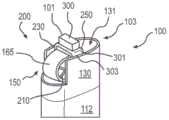
图5描绘了负压泵100的第二示例性实施方案。具体地,图5中所示的实例可用于单次使用,例如完全一次性使用。一次性负压泵100包含适合于单次使用的一种材料或多种材料,包括但不限于:塑料、玻璃、金属、聚硅氧烷、或它们的组合。至少一部分的负压泵100可以是不透明的、透明的、或半透明的。负压泵100可具有任意合适的截面形状,包括但不限于:矩形、圆形、椭圆形、三角形、或卵形。FIG. 5 depicts a second exemplary embodiment of the
在至少一个实施方案中,负压泵100可包括第一端100a、壁100b、和第二端100c。第一端100a可以是负压泵100的固体形态的截面。例如,如果负压泵100包括具有椭圆形截面的塑性结构,那么第一端100a可以是塑性椭圆体。在至少一个实施方案中,第一端100a可包括用于启动按钮101的开口。启动按钮101可呈可从第一端100a中延伸出的任意形状。例如,启动按钮101可以是突出物、锁栓、开关、或它们的任意组合。In at least one embodiment, the
在至少一个实施方案中,壁100b可具有外表面和内表面。在至少一个实施方案中,壁100b的外表面可包括标志或其他标记,例如指示体积。壁100b的外表面可进一步包括防滑涂层、凸起、突出物、胶粘剂、或它们的组合,以便于操作。在至少一个实施方案中,壁100b的内表面可形成腔体112。驱动外壳103、弹簧105、和柱塞107都可容纳于腔体112内部。至少一部分的腔体112可用作贮室109。在一个实施方案中,壁100b的内(或腔体)表面可以是平滑的。In at least one embodiment, the
在至少一个实施方案中,可将驱动外壳103设置在腔体112顶部且与第一端100a相邻的位置。驱动外壳103可容纳由启动按钮101启动的驱动机构。驱动外壳103可包含适合于单次使用的任意一种材料或多种材料,包括但不限于:塑料、玻璃、金属、聚硅氧烷、或它们的组合。下面关于图6A-图7C更详细地描绘了驱动外壳103和容纳于其中的驱动机构。In at least one embodiment, the
弹簧105可包括任意合适类型的弹簧,例如螺旋弹簧、扭转弹簧、时钟弹簧等。在图5的装置中,可偏置弹簧105以便回缩至驱动外壳103中。在一些实施方案中,弹簧105可包括不储存能量的金属丝或线缆。在至少一个实施方案中,在启动按钮101的启动时,弹簧105可收回至驱动外壳103中。可将弹簧105的一端紧固于驱动外壳103内部,并且弹簧105的另一段可附接或联接到柱塞107。在默认位置,在负压泵100的使用之前,柱塞107可位于负压泵100的第二端100c。这会意味着,在默认位置,弹簧105可延长经过腔体112的长度,例如弹簧105可从驱动外壳103(与第一端100a相邻)伸展到柱塞107(在第二端100c)。弹簧105可包括附接到驱动机构的构件的一个或多个弹簧和/或线缆。在至少一个实施方案中,弹簧105可包括弹簧部及线缆或金属丝部。
在至少一个实施方案中,柱塞107可具有与腔体112大致相同的截面。柱塞107可包括顶部107a、侧壁107b、和底部107c。在至少一个实施方案中,顶部107a可固定地附接到弹簧105。柱塞侧壁107b可与壁100b的内表面齐平。例如,柱塞侧壁107b可与壁100b的内表面直接地接触,或者密封件(诸如O形圈)可在柱塞侧壁107b和壁100b的内表面之间并且与它们直接地接触。当负压泵100在默认位置时,柱塞底部107c可位于泵第二端110c。当负压泵100在使用中时,柱塞107可沿腔体112朝向驱动外壳103移动(例如,柱塞107可沿壁100b的内表面滑动)。In at least one embodiment, the
在一个实施方案中,泵第二端100c可包括基部111和分流管接头113。在至少一个实施方案中,基部111可将由泵壁100c所形成的腔体加以封闭。在至少一个实施方案中,柱塞底部107c的默认位置可在腔体112的内部并且与基部111的顶部相邻,例如在基部111的顶部上。基部111可包括开口,该开口包括分流管接头113。该开口可提供对由壁100b所形成腔体的进入。分流管接头113可包括阀(例如单向阀),该阀可附接到管道,该管道延伸至靶部位(例如在患者的身体上或内部),从而允许体液进入贮室109但防止体液从贮室109中液漏。In one embodiment, the pump
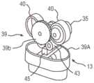
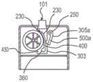
图6A-图6C包括驱动外壳103的各种视图和示例性驱动组件200。因为泵100可为了一次性使用而制造,泵100的一次性驱动组件200可包括更少的部件并且/或者采用与可重复使用驱动单元11的驱动构30所不同的机构。此外,例如,驱动组件200可释放并存放弹簧(如本文中进一步的描述),而驱动机构30可主动地抵抗其偏置位置(状态)移动弹簧。图6A-图6C更详细地描绘了示例性驱动组件200和相关部件。FIGS. 6A-6C include various views of the
如在图6A中所示,驱动外壳103可包括壁130。在至少一个实施方案中,壁130可具有与腔体112相对应的截面。壁130可限定其自身的腔体131。在至少一个实施方案中,壁130可包括切槽150。切槽150可包括处在与壁130的另一个部分不同高度的壁130的一部分。切槽150可具有任意适当的形状或尺寸。在至少一个实施方案中,切槽150可提供对驱动组件200的进入。例如,驱动组件200可位于腔体131内部。在腔体131的整个周长上为相同高度的壁130会阻止向驱动组件200的进入。切槽150可使至少一部分的驱动组件200暴露。As shown in FIG. 6A , the
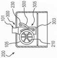
如在图6A-图6C中所示,驱动组件200可包括启动按钮101、弹簧105、毂210、楔块230、和锁栓250。图6B和图6C具体地示出了启动按钮101、楔块230、和锁栓250的示例性构造。在至少一个实施方案中,启动按钮101可包括突出物300、支架301、和臂303(例如,如在图6A和图6B中所示)。启动按钮臂303可进一步包括凹口305(示于图6C并且在下面更详细地说明)。在至少一个实施方案中,突出物300可以是从泵100顶部延伸出的启动按钮101的一部分。使用者通过推动突出物300可启动泵100。突出物300可具有任意形状,包括但不限于矩形(如在图6A-图6C中所示)、圆形、正方形、星形、或椭圆形等。突出物300任选地可包括凹槽或防滑表面,以便于操作。As shown in FIGS. 6A-6C , drive assembly 200 may include
在至少一个实施方案中,可将突出物300设置在支架301顶部上。支架301可包括表面,该表面将突出物300连接到臂303。在至少一个实施方案中,臂303可在弹簧105的任一侧上延伸。例如在图6B中所示,可将弹簧105设置在臂303a与臂303b之间(“臂303”)。在至少一个实施方案中,臂303也可安装在楔块230上方并且将楔块230保持在抵接弹簧105的状态(而在泵100的使用前处在默认位置)。在至少一个实施方案中,每个臂303可包括在一侧的凹口305。例如,图6C示出了带凹口305a的臂303a。锁栓250可位于与臂303的凹口305相同的一侧。In at least one embodiment,
在至少一个实施方案中,弹簧105可包括设置在毂210上的缠绕驱动弹簧。弹簧105可解开并且/或者卷绕于毂210上。在至少一个实施方案中,毂210可包括轮、套管、橡胶辊、或者可以捕获弹簧105使得弹簧105保持解开状态的任何部件。可利用延伸穿过泵100(如在图6C中所示)的轴将毂210固定,使得毂210围绕该轴旋转。In at least one embodiment, the
在至少一个实施方案中,楔块230可包括可枢转臂400,该臂400具有设置在臂400一端的停止器450。在默认位置,启动按钮101的臂303可将停止器450保持为抵接弹簧105(例如,如在图6C和图7A中所示)。In at least one embodiment, the
锁栓250可包括杆500,该杆500将锁定臂500a连接到锁定臂500b(“锁定臂500”),如在图6B中所示。在至少一个实施方案中,杆500可位于启动按钮101的臂303的旁边。杆500可将锁定臂500保持在与凹口305相邻的位置(如在图6C中所示)。在至少一个实施方案中,每个锁定臂500的至少一部分可延伸进入每个凹口305的至少一部分中。例如,锁定臂500a可嵌入凹口305a中。图7A-图7C更详细地说明了锁定臂500与凹口305的相互作用。The
图7A-图7C描绘了驱动组件200的示例性操作。在图7A中所示的一个示例性默认位置,启动按钮101不被按下。突出物300可完全地从泵100的第一端向上延伸并且驱动组件200的内部部件可处于静止状态(例如,不在运动中),包括完全地延伸至贮室109底部的弹簧105。在至少一个实施方案中,楔块230的停止器450可抵靠弹簧105。因此,毂210和弹簧105是固定且静止的。此外,锁栓250的锁定臂500可各自,在凹口305下方且与凹口305相邻位置,抵靠启动按钮臂303的表面(参见图6C)。7A-7C depict exemplary operation of the
当启动按钮101被按下时(如在图7B中所示),突出物300可延伸进入泵100的第一端100a中。支架301(参见图6A和图6B)可将向下运动转移至臂303。因为楔块230可联接到臂303,所以臂303的向下运动可推动停止器450(和/或)的向下运动和细长臂400的枢转。楔块230的运动可释放弹簧105,并且弹簧105可开始卷绕于毂210上。换句话说,按钮101的按下可释放弹簧105,这可导致弹簧105由于其偏置并收回而收回于毂210上。When the
通过完成突出物300的行程,臂303可充分地降低以允许锁定臂500枢转并进入它们的相应凹口305中(如在图7C中所示)。锁栓250可永久地卡住启动按钮101和楔块230。By completing the travel of the
图8A-图8D图解说明了使用负压泵100的示例性方法,其中整个泵装置可以是单次使用的。泵100可包括由弹簧提供动力的负压驱动组件200,该负压驱动组件具有附接的体液贮室109。具体地,泵100可包括拉伸的弹簧105,该弹簧附接到位于贮室109底部的柱塞107(例如,如在图8A中所示)。管的一端可连接到分流管连接件113,并且其他管端部与创伤腔或者需要体液收集的患者身体的其他部分或靶部位流体连通。压下按钮(例如,启动按钮101)可释放驱动组件200中的楔块停止器(未图示)。在使用之前(例如,在制造期间)可装载该弹簧以储存能量。因此,楔块停止器的释放可导致弹簧105收回(例如,如在图8B中所示)。因为弹簧105连接到柱塞107,所以弹簧105的卷绕可拉动柱塞107经过贮室腔体112并在贮室109中产生负压。在至少一个实施方案中,弹簧105的一端可连接到柱塞107。在一些实施方案中,弹簧105可经由线缆而联接到(例如附接到)柱塞107,使得弹簧105的释放拉动线缆,并且拉动附接到柱塞107的线缆以在贮室109中产生负压。贮室109中的负压可允许贮室109从靶部位(例如患者的)抽吸并收集体液(例如,如在图8C中所示)。当贮室109是满的并且/或者期望量的体液被吸入贮室109中时,管道任选地可与分流管接头113分离(例如,如在图8D中所示)。然后可将整个装置(泵100)丢弃。8A-8D illustrate an exemplary method of using the
图9A和图9B示出了包括扭转弹簧的另一个示例性装置。当弹簧被卷绕时由扭转弹簧所产生的转矩可增加并且当弹簧被解开时减小。然而,在柱塞上的大致恒定的力(和大致恒定的负压)会是理想的。在金属丝或其他类型线缆中的张力可以以弹簧转矩除以滑轮半径的方式而进行计算。该金属丝可以被捕获于滑轮中的凹槽中。当弹簧解开并且转矩减小时,其中金属丝离开滑轮处的滑轮半径减小。如果维持弹簧转矩与滑轮直径(其中金属丝离开)的比率,则可以维持恒定的力。9A and 9B illustrate another exemplary device including a torsion spring. The torque produced by the torsion spring may increase when the spring is coiled and decrease when the spring is unwound. However, a substantially constant force (and a substantially constant negative pressure) on the plunger would be ideal. The tension in a wire or other type of cable can be calculated as the spring torque divided by the pulley radius. The wire can be captured in grooves in the pulley. As the spring unwinds and the torque decreases, the radius of the pulley where the wire leaves the pulley decreases. A constant force can be maintained if the ratio of the spring torque to the pulley diameter (where the wire leaves) is maintained.
图10A-图10B示出了采用类似于图9A和图9B的原理的布置。此外,关于与如何可以卷绕或释放弹簧有关联的机制,这些附图不是详尽无遗的。这些附图示出了从时钟弹簧(例如,卷绕多芯带状线缆)中得到恒定力的方法,这些弹簧可提供振荡转矩或脉动转矩。图10A-图10C示出了两个滑轮,这两个滑轮附接到时钟弹簧,因此当时钟弹簧解开时这些滑轮可旋转。可将传动带包缠于滑轮周围并且两个滑轮的每个滑轮附接到变螺距丝杠,以便可将时钟弹簧的转矩和运动传递至这两个丝杠。金属丝可从在丝杠上的螺母连接到柱塞,以便可将螺母上的力施加至柱塞,从而产生负压。螺母上的力可与将螺杆上的转矩除以螺纹导程的商成比例,并且螺杆上的转矩可与弹簧中的转矩成比例。因此,即使在其中弹簧转矩不是恒定的情况下,如果弹簧转矩与螺纹导程的比率是恒定的,则可以维持恒定或大致恒定的力。Figures 10A-10B illustrate arrangements employing principles similar to those of Figures 9A and 9B. Furthermore, these figures are not exhaustive as to the mechanisms associated with how the spring may be wound or released. These figures illustrate a method of obtaining constant force from clock springs (eg, wound multi-conductor ribbon cables) that provide oscillating or pulsating torque. Figures 10A-10C show two pulleys attached to the clock spring so they can rotate when the clock spring is unwound. A drive belt can be wrapped around the pulleys and each of the two pulleys is attached to the variable pitch lead screw so that the torque and motion of the clock spring can be transferred to the two lead screws. A wire can be connected from the nut on the lead screw to the plunger so that the force on the nut can be applied to the plunger, creating a negative pressure. The force on the nut can be proportional to the torque on the screw divided by the thread lead, and the torque on the screw can be proportional to the torque in the spring. Thus, even in situations where the spring torque is not constant, a constant or approximately constant force can be maintained if the ratio of the spring torque to the thread lead is constant.
图11A和图11B可在概念上类似于图9A和图9B的实施方案,除了使用时钟弹簧来代替金属丝扭转弹簧(例如,螺旋弹簧)并且可将两条金属丝包缠于相同的锥形滑轮上以外。如果维持弹簧转矩与滑轮(金属丝离开处)直径的比率,则可以维持恒定的力。Figures 11A and 11B may be conceptually similar to the embodiments of Figures 9A and 9B, except that a clock spring is used instead of a wire torsion spring (eg, a coil spring) and two wires may be wrapped around the same cone off the pulley. A constant force can be maintained if the ratio of the spring torque to the diameter of the pulley (where the wire leaves) is maintained.
图12示出了其中可以将装置顶部上的“旋钮”扭转以便给齿轮传动机构中的弹簧或线缆进行赋能的布置。在这个概念中,柱塞可在贮室的底部开始,并且可将附接到柱塞的线缆包缠于在贮室顶部的滑轮。例如,该线缆可附接到或固定到在滑轮上的线缆附接点。当旋钮被卷绕时,线缆可包缠于滑轮(在至少一个实施方案中,线缆几乎是平直的而不是松弛的)。在此构造中,齿轮传动机构可以与贮室分离。使齿轮传动机构与滑轮接合可收卷线缆并且使柱塞移动。Figure 12 shows an arrangement in which a "knob" on the top of the device can be twisted to energize a spring or cable in the gear mechanism. In this concept, the plunger can start at the bottom of the reservoir, and the cable attached to the plunger can be wrapped around the pulley at the top of the reservoir. For example, the cable may be attached or secured to a cable attachment point on the pulley. When the knob is coiled, the cable can wrap around the pulley (in at least one embodiment, the cable is nearly straight rather than slack). In this configuration, the gear mechanism can be separated from the reservoir. Engaging the gear mechanism with the pulley rewinds the cable and moves the plunger.
图13A-图13F示出了根据本公开一些实施方案的示例性压力致动负压泵。在至少一个实施方案中,每1mL体液可产生260mL的蒸气,从而导致260mL的可能收集体液体积。该体液可以是单一体液或者不同体液的混合物,其具有处在或近似大气压力(760mmHg)加上期望的装置真空压力(例如,125mmHg)加上系统中的机械损失(例如,700mmHg)的蒸气压。因此,在20℃下可采用近似1585mmHg的蒸气压。可以产生此蒸气压的示例性流体混合物是正己烷与正丁烷的混合物。许多其他流体和流体混合物也是可行的。13A-13F illustrate an exemplary pressure-actuated negative pressure pump according to some embodiments of the present disclosure. In at least one embodiment, 260 mL of vapor can be generated per 1 mL of body fluid, resulting in a possible collected body fluid volume of 260 mL. The body fluid may be a single body fluid or a mixture of different body fluids having a vapor pressure at or near atmospheric pressure (760 mmHg) plus the desired device vacuum pressure (eg, 125 mmHg) plus mechanical losses in the system (eg, 700 mmHg) . Thus, a vapor pressure of approximately 1585 mmHg can be employed at 20°C. An exemplary fluid mixture that can generate this vapor pressure is a mixture of n-hexane and n-butane. Many other fluids and fluid mixtures are also possible.
在至少一个实施方案中,在制造期间可将1mL的正己烷/正丁烷混合物放置于装置的正压室1550中。可将该室的柱塞1560锁定,直到使用者启动该装置。该装置可被设计用于处理在存放期期间该混合物的压力,非常类似手持打火机。在启动时,可推动正压室1550中的柱塞1560,从而增加该室的体积并因此也增加负压室1555的体积,因此产生期望的真空压。该流体混合物的体积当它从液体转变成蒸气时可增大例如260倍(1mL增大到260mL),同时维持相同的蒸气压。在250mL贮室真空装置的这种实施方案中,小于1mL的流体可以用于启动该装置。图13A-图13F的装置1600可包括两个室(一个正压室1550、和一个负压室1555),各室具有由刚性结构所连接的柱塞1560。正压室1550可容纳流体的混合物,该混合物产生蒸气压从而导致正压。最初可将柱塞1560锁定在贮室底部,如由图13E所示。当锁定机构被释放时,柱塞1560移动,从而在负压室1555中产生负压。柱塞1560可经过压力室1550和1555移动至最终位置,如在图13F中所示。在装置顶部1601上的槽1603可以是通往大气压的排气口。该整个装置1600可以是一次性或可重复使用的装置。In at least one embodiment, 1 mL of the n-hexane/n-butane mixture can be placed in the
图14A和图14B示出了包括转矩弹簧的另一个示例性负压泵1700的实施方案。负压泵1700可具有任意合适的截面形状,包括但不限于:矩形、圆形、椭圆形、三角形、或卵形。负压泵1700可包含任意合适的一种材料或多种材料,包括但不限于:玻璃、塑料、金属、橡胶、聚硅氧烷、或它们的组合。至少一部分的负压泵1700可以是不透明的、透明的、或半透明的。14A and 14B illustrate another exemplary
负压泵1700可包括驱动组件外壳1701和贮室1703。外壳1701与贮室1703可在接口1702处连接。接口1702可包括在一部分的外壳1701和一部分的贮室1703中的重叠部分,如在图14A和14B中所示。例如,该部分的外壳1701的可构造成嵌入贮室1703内部并抵接该部分的贮室1703的内表面。作为一个替代实施方案,一部分的贮室1703可构造成嵌入外壳1701内部并抵接外壳1701的内表面。外壳1701和贮室1703的同心圆周可形成接口1702。The
在至少一个实施方案中,可将外壳1701与贮室1703固定地联接,因而接口1702是永久的。例如,可利用胶、其他胶粘剂、或另一种永久固定的方法,在接口1702处将外壳1701与贮室1703粘附到一起。在一些实施方案中,泵1700可包括一个单一整体单元。在这种情况下,可在制造期间将外壳1701与贮室1703形成为单一整体单元(例如,由一种材料),而不是通过将外壳贮室1701与贮室1703连接到一起而形成。在一些实施方案中,可将外壳1701与贮室1703可移除地联接,以便可在接口1702处将外壳1701从贮室1703中释放或分离。例如,可通过卡扣配合、摩擦配合、或其他可释放接合,在接口1702处将外壳1701与贮室1703连接。在这种情况下,可将外壳1701从贮室1703中释放出(例如,在贮室1703是满的之后)。然后,外壳1701可联接到第二贮室并重新使用。In at least one embodiment, the
驱动组件外壳1701可包括驱动组件1705。驱动组件1705可由具有锁定机构(在图14E和图14F中更详细地示出)的致动器(例如,按钮1707)启动。驱动组件1705可包括弹簧存放鼓1709、弹簧1711(例如,恒转矩弹簧)、和具有线缆附接点1715的输出鼓1713。在至少一个实施方案中,按钮1707可以可移除地将输出鼓1713和存放鼓1709锁定在固定位置。弹簧存放鼓1709和输出鼓1713可各自包括圆柱形存放单元,该存放单元构造成并且尺寸被设计成容纳弹簧1711。弹簧1711可具有平面的或带状的结构,并且是由金属、合金、塑料、弹性体、电活性聚合物等、或它们的组合制成。弹簧1711可由柔性材料制成并且具有允许弹簧从输出鼓1713解开到弹簧存放鼓1709上的厚度。在制造期间,弹簧1711可被容纳于输出鼓1713上同时在默认位置。另外,在制造期间,通过将弹簧1711卷绕于输出鼓1713上,可使弹簧1711偏置并赋能给该弹簧。在使用期间,当利用按钮1707将鼓从它们的固定位置释放时,弹簧1711可从输出鼓1713卷绕于存放鼓1709上。Drive
驱动组件1705可驱动柱塞的运动。例如,输出鼓1713的线缆附接点1715可以是用于线缆1717的连接点。线缆1717可以是任意合适的柔性细长构件。例如,线缆1717可包括金属丝、绳、绳索、细绳等。线缆1717可延伸经过贮室1703同时在默认位置。线缆1717的一端可附接到线缆附接点1715并且线缆1717的第二端可连接到柱塞1719。柱塞1719可抵接贮室1703内表面形成密封,例如利用在图14A和图14B中所示的O形圈1721、或其他合适的环形密封。柱塞1719可具有在贮室1703基部1723的默认位置。例如,当柱塞1719在其默认位置时,柱塞1719的下表面可与基部1723的表面接触。因此,在来自制造的默认位置,线缆1717可延伸经过贮室1703:线缆1717的一端可在驱动组件1705处连接到输出鼓1713并且另一端可在贮室1703的基部1723连接到柱塞1719。在泵使用期间,输出鼓1713的旋转可导致线缆1717卷绕于输出鼓1713的轴上并且拉动柱塞1719经过贮室1703的长度。换句话说,线缆1717可收回并导致柱塞1719从贮室1703基部1723朝向驱动组件1705移动。柱塞1719可经过贮室1703的腔体、沿由贮室1703所限定的纵向轴线(例如,其中该纵向轴线可类似于图1的轴线x)而移动。The
贮室1703的基部1723可包括接头1725,该接头构造成接纳分流管(例如,患者治疗单元的分流管)。接头1725可包括用于控制压力的阀,例如,使得泵1700不立即“失去”压力,即使分流管尚未附接到接头。该阀可包括构造成允许体液进入(但不离开)贮室1703的单向阀。当柱塞1719移动经过贮室1703时,可将体液从患者治疗单元吸入贮室1703中。柱塞1719可形成贮室1703的体液与驱动组件1705之间的阻隔。The
可在制造期间组装泵1700,以便给弹簧1711进行赋能并且柱塞1719是在贮室1703的基部1723。可将弹簧输出鼓1713锁定(关于图14E和图14F所描述),因而线缆1717是松弛的。当泵1700准备使用时,使用者可将分流管附接到接头1725并按下按钮1707。按下按钮1707可将驱动组件1705解锁,从而导致在输出鼓1713上的转矩产生在线缆1717中的张力。线缆1717中的张力可导致在柱塞1719上的向上力,从而拉动柱塞1719经过贮室1703。当弹簧1711解开并且线缆1717卷绕于输出鼓1713上时,该力可保持恒定。柱塞1719的运动可产生恒定的负压并且将体液从分流管中经过接头1725中的阀吸入贮室1703中。当贮室1703是满的并且/或者期望量的体液从靶部位被排除时,使用者可将分流管与接头1725分离。The
图14C和图14D提供了图14A和图14B的负压泵的示例性驱动组件的分解视图。如在图14C和图14D中所示,驱动组件外壳1701可包括两个分离的半部,各半部具有外表面1800和边缘表面1802。通过使各半部中的外壳固定件803a配对,或者利用永久或可释放接合的任意其他合适方法,可将驱动组件外壳1701的半部在它们的边缘表面1802处连接到一起。驱动组件外壳1701也可包括分离的可压缩构件1801。构件1801的外表面对于使用者而言会是可及的。同时,构件1801的内表面可紧靠按钮1707,例如对于使用者而言是不可及的。驱动组件外壳1701可包括在驱动组件外壳1701内表面内部的固定件1803a、1803b、和1803c。固定件1803a可使驱动组件外壳1701的两个半部对准并且有助于将这两个半部相互紧固。固定件1803b可进一步定位驱动组件外壳1701的两个半部,定位存放鼓1709和输出鼓1713,并且/或者提供结构支撑以便驱动组件外壳1701。固定件1803c(示于图14C)可容纳存放鼓1709和输出鼓1713的主轴1805。固定件803b和803c可构造成允许主轴1805旋转,使得一旦按钮1707被启动那么存放鼓1709和输出鼓1713可自由地旋转。按钮1707可包括紧靠构件1801内表面的头部1807、和延伸至少输出鼓1713的长度的尾部1809。在至少一个实施方案中,尾部1809可包括细长构件,该细长构件具有从尾部1809的纵向中心轴线中延伸出的一个或多个肋片或肋条。14C and 14D provide exploded views of an exemplary drive assembly of the negative pressure pump of FIGS. 14A and 14B. As shown in FIGS. 14C and 14D , the
图14E和图14F提供了图14A和图14B的负压泵的示例性驱动组件锁定的视图。在图示的实施方案中,按钮1707的尾部1809包括按钮锁定突片1811。按钮锁定突片1811可以以垂直于尾部1809纵向轴线的方式而延伸并与输出鼓1713接触。图14E进一步提供了其中按钮1707的尾部1809可包括按钮位置阻挡部1813的一个实施方案,该按钮位置阻挡部1813可沿尾部1809的纵向轴线而延伸并延伸进入由驱动组件外壳1701的固定件803a所形成的腔中。图14F提供了包括在按钮1707的头部1807处的按钮位置阻挡部1813的一个实施方案。按钮位置阻挡部1813可稳定或保持按钮1707的位置。例如,如在图14E中所示,可利用与按钮1707的头部1807接合的构件1801而使按钮1707位于驱动组件外壳1701内部,并且驱动组件外壳1701的固定件803c的内部容纳在按钮1707的尾部1809处的按钮位置阻挡部1813。14E and 14F provide views of exemplary drive assembly locking of the negative pressure pump of FIGS. 14A and 14B . In the illustrated embodiment, the
在至少一个实施方案中,输出鼓1713可包括锁定肋1815,该锁定肋1815可与按钮锁定突片1811重叠并紧靠按钮锁定突片1811。例如,输出鼓1713可包括带基部1817的圆筒。基部1817可被定位成垂直于圆筒的纵向轴线。基部1817可容纳可形成锁定肋1815的肋条、肋片、或突出物。在至少一种情况下,锁定肋1815可被定位成使得它们不在与弹簧1711接触的输出鼓1713的表面上。锁定肋1815可以以相等的间隔从输出鼓1713的中心(如在图14E中所示)或沿基部1817的圆周(如在图14F中所示)而延伸。在默认位置,按钮锁定突片1811通过紧靠输出鼓锁定肋1815可保持输出鼓1713的位置。使用者可通过按下(图14C或图14D的)构件1801操作泵1700,从而在外壳固定件803c的方向上使按钮1707的尾部1809位移。尾部1809朝向外壳固定件1803c的运动可使按钮锁定突片1811发生位移,使得按钮锁定突片1811不再紧靠输出鼓锁定肋1815。此运动由于弹簧1711的预先设置的偏置因而可释放输出鼓1713并使其旋转。输出鼓1713的旋转将线缆1717和柱塞1719(图14A和14B的)收回,从而允许体液被吸入贮室1703中。In at least one embodiment, the
在至少一个实施方案中,输出鼓1713可包括单个锁定肋1815。在一些实施方案中,输出鼓1713可包括多个锁定肋1815,例如围绕输出鼓1713的多个均等间隔肋条(如在图14E或图14F中所示)。多个锁定肋1815可在泵1700的制造中提供制造公差。例如,多个锁定肋1815仅允许输出鼓1713旋转直到按钮锁定突片1811抵靠至少一个鼓锁定肋1815。输出鼓1713上的锁定肋1815越多,则在按钮锁定突片1811与锁定肋1815接触之前输出鼓1713能旋转的越少。In at least one embodiment, the
在至少一个实施方案中,泵1700构造成仅被启动一次。例如,泵1700的结构可被设计成使得按钮1707不与表面1801重新接合并且按钮锁定突片1811不与肋条1815重新接合。在一些实施方案中,可间断地启动泵1700。例如,可使按钮1707偏置以使其与表面1801接触,例如利用位于尾部1809的弹簧。在一种这样的情况下,仅当按钮1707被按下时,泵1700可将体液吸入贮室1703中。例如,当按钮1707被按下时,按钮锁定突片1811可释放输出鼓1713使其旋转,从而解开弹簧1711并收回线缆1717。当按钮1707不被按下时,按钮锁定突片1811可再次紧靠输出鼓锁定肋1815并停止输出鼓1713的旋转,因为可使按钮1707偏置以使其与表面1801接触。输出鼓1713上的多个筒锁定肋1815可确保当按钮1707不被按下时输出鼓1713不转动达全程旋转。该实施方案给使用者提供开始、停止、和重新开始体液进入贮室1703的抽吸的能力,而不是仅提供关于何时开始体液抽吸的控制。在至少一个实施方案中,可控制输出鼓1713的转速,例如利用梯度按钮锁定突片1811,该突片可根据按钮1707被按下的程度而改变输出鼓1713的转速。这种情况给使用者提供控制体液进入贮室腔体中的收回速度的能力。在一些实施方案中,线缆1717的收回可以以恒定的速度发生,使得体液可以以恒定的速度被吸入贮室中。In at least one embodiment, the
如在图14F和图14G中所示,泵1700可包括弹簧卷绕齿轮1819和齿轮进入孔1821。弹簧卷绕齿轮1819和齿轮进入孔1821可允许泵1700的初始启动、间断的体液抽吸、或泵1700的重新使用。例如,弹簧卷绕齿轮1819和齿轮进入孔1821可用于将弹簧1711卷绕至输出鼓1713并因此给弹簧1711赋能。作为上下文,在制造之前,可将弹簧1711缠绕于处在默认状态中的存放鼓1709上。当弹簧1711在存放鼓1709上时,弹簧1711可不被赋能。在制造期间当弹簧1711从存放鼓1709被卷绕至输出鼓1713时,可给弹簧1711进行赋能,例如通过使用经过齿轮进入孔1821而与小齿轮1823接合的弹簧卷绕齿轮1819,如下面进一步的描述。As shown in FIGS. 14F and 14G , the
图14F图解说明了其中可将弹簧卷绕齿轮1819定位于输出鼓1713的基部1817上的一个示例性实施方案。在至少一个实施方案中,弹簧卷绕齿轮1819可与输出鼓1713为同轴的并且具有比输出鼓1713更小的半径。弹簧卷绕齿轮1819可包括沿其外圆周的齿1820。FIG. 14F illustrates an exemplary embodiment in which the
齿轮进入孔1821可以是在驱动组件外壳1701中的开口(如在图14F和14G中所示)。齿轮进入孔1821可偏离弹簧卷绕齿轮1819的中心轴线和其大部分(如在图14G中所示),使得经过齿轮进入孔1821所插入的小齿轮1823可与弹簧卷绕齿轮1819接合。具体地,如在图14H和图14I中所示,小齿轮1823可包括圆柱形的杆,该杆具有沿其外圆周至少一部分的联锁齿1825。小齿轮1823的联锁齿1825可与弹簧卷绕齿轮1819的齿1820接合。在至少一个实施方案中,使小齿轮1823顺时针转动同时使联锁齿1825与齿1820接合可将弹簧1711从存放鼓1709卷绕至输出鼓1713。
如在图14I中所示,固定件831可用于将小齿轮1823引导入齿轮进入孔1821中,维持小齿轮1823的位置,并且保持小齿轮1823的位置与弹簧卷绕齿轮1819对正。虽然图14I示出了正在用手使其转动的小齿轮1823,但可采用任意的多种卷绕方法,包括装电机的卷绕机构。As shown in FIG. 14I , retainer 831 can be used to guide
在至少一个实施方案中,齿轮进入孔1821可仅在泵1700的工厂组装期间可及(例如,在操作期间使用者不可及以排除体液)。例如,齿轮进入孔1821可仅在将驱动组件外壳1701与贮室1703进行组装之前是可及的。因此,弹簧1711可仅在工厂组装期间进行卷绕,而不是在泵1700的使用之前、期间、之后由最终用户进行卷绕。在一种情况下,可在泵1700离开厂址之前,将齿轮进入孔1821加以密封。In at least one embodiment, the
如在图14J(其描绘了三个泵的前视图和后视图)中所示,负压泵1700可具有任意的多种尺寸,例如由泵2000a和泵2000b所示的500mL尺寸、由泵2100a和泵2100b所示的300mL尺寸、及由泵2200a和泵2200b所示的150mL尺寸。As shown in Figure 14J (which depicts front and rear views of three pumps),
上面的描述和实例是说明性的,而并非意图是限制性的。本领域技术人员可在不背离本发明一般范围的前提下作出许多修改和/或变更。例如,并且如已描述的,上述各实施方案(和/或其方面)可彼此结合使用。此外,在不背离本发明的范围的前提下,可去除上述各实施方案的部分。另外,在不背离它们的范围的前提下,可作出修改以使特定的情况或方面适应于各种实施方案的教示。在回顾以上描述时,许多其他各实施方案对于本领域技术人员也将是显而易见的。The above description and examples are illustrative and not intended to be limiting. Numerous modifications and/or changes may be made by those skilled in the art without departing from the general scope of the invention. For example, and as already described, the various embodiments (and/or aspects thereof) described above may be used in conjunction with each other. Furthermore, parts of the various embodiments described above may be removed without departing from the scope of the present invention. In addition, modifications may be made to adapt a particular situation or aspect to the teachings of various embodiments without departing from their scope. Many other various embodiments will also be apparent to those skilled in the art upon reviewing the above description.
此外,虽然描述了本文中所描述各实施方案(及其变型)的若干目的和优点,但根据任何具体实施方案未必可实现所有的这种目的或优点。因此,例如本领域技术人员将认识到,本文中所描述的系统和技术可以在未必实现如可在本文中所教示或提出的其他目的或优点的情况下,以实现或优化如本文中所教示一个优点或一组优点的方式而具体化或实施。Furthermore, although several objects and advantages of the various embodiments described herein (and variations thereof) have been described, not all such objects or advantages may be realized according to any particular implementation. Thus, for example, those skilled in the art will recognize that the systems and techniques described herein may be achieved or optimized as taught herein without necessarily achieving other objectives or advantages as may be taught or suggested herein An advantage or group of advantages can be embodied or carried out.
Claims (20)
Translated fromChineseApplications Claiming Priority (5)
| Application Number | Priority Date | Filing Date | Title |
|---|---|---|---|
| US201862651407P | 2018-04-02 | 2018-04-02 | |
| US62/651,407 | 2018-04-02 | ||
| US201962820912P | 2019-03-20 | 2019-03-20 | |
| US62/820,912 | 2019-03-20 | ||
| PCT/US2019/025120WO2019195134A1 (en) | 2018-04-02 | 2019-04-01 | Negative pressure pumps and related methods |
Publications (1)
| Publication Number | Publication Date |
|---|---|
| CN112165961Atrue CN112165961A (en) | 2021-01-01 |
Family
ID=66175507
Family Applications (1)
| Application Number | Title | Priority Date | Filing Date |
|---|---|---|---|
| CN201980034693.7APendingCN112165961A (en) | 2018-04-02 | 2019-04-01 | Negative pressure pump and related methods |
Country Status (4)
| Country | Link |
|---|---|
| US (1) | US10548778B2 (en) |
| EP (1) | EP3773778A1 (en) |
| CN (1) | CN112165961A (en) |
| WO (1) | WO2019195134A1 (en) |
Families Citing this family (4)
| Publication number | Priority date | Publication date | Assignee | Title |
|---|---|---|---|---|
| JP6787903B2 (en) | 2015-01-27 | 2020-11-18 | メディヴァンス インコーポレイテッドMedivance,Inc. | Improved medical pads and systems for hyperthermia |
| WO2017139394A1 (en)* | 2016-02-09 | 2017-08-17 | Kci Licensing, Inc. | A negative-pressure therapy apparatus with push-to-release actuator |
| US12433785B2 (en) | 2021-02-23 | 2025-10-07 | C. R. Bard, Inc. | Gel pad assembly using free rotatable fluid joints |
| US12241570B2 (en) | 2021-07-07 | 2025-03-04 | C. R. Bard, Inc. | Negative pressure connector seal |
Citations (5)
| Publication number | Priority date | Publication date | Assignee | Title |
|---|---|---|---|---|
| US20100042021A1 (en)* | 2008-02-14 | 2010-02-18 | Spiracur, Inc. | Devices and methods for treatment of damaged tissue |
| US20100228205A1 (en)* | 2009-03-04 | 2010-09-09 | Spiracur Inc. | Devices and methods to apply alternating level of reduced pressure to tissue |
| CN102498292A (en)* | 2009-07-23 | 2012-06-13 | 斯维斯诺弗产品责任有限公司 | Fluid delivery system comprising a fluid pumping device and a drive system |
| CN106924831A (en)* | 2017-03-24 | 2017-07-07 | 陈云松 | A kind of Portable Automatic negative pressure drainage device |
| US20170224885A1 (en)* | 2016-02-09 | 2017-08-10 | Kci Licensing, Inc. | Negative-Pressure Therapy Apparatus With Push-To-Release Actuator |
Family Cites Families (58)
| Publication number | Priority date | Publication date | Assignee | Title |
|---|---|---|---|---|
| US3447479A (en)* | 1967-06-02 | 1969-06-03 | Pall Corp | Syringe pump |
| US3841331A (en)* | 1972-11-17 | 1974-10-15 | J Wilder | Suction-pump assembly for drawing body fluids |
| US5011381A (en)* | 1989-09-22 | 1991-04-30 | Neward Theodore C | Hand-held vacuum pump vacuum release |
| US6129181A (en) | 1998-05-26 | 2000-10-10 | Lockheed Corp | Constant force spring actuator |
| US6669668B1 (en) | 1999-11-05 | 2003-12-30 | Tandem Medical | Medication delivery pump |
| US6685681B2 (en)* | 2000-11-29 | 2004-02-03 | Hill-Rom Services, Inc. | Vacuum therapy and cleansing dressing for wounds |
| US6716226B2 (en) | 2001-06-25 | 2004-04-06 | Inscope Development, Llc | Surgical clip |
| US7156803B2 (en) | 2002-08-19 | 2007-01-02 | Depuy Spine, Inc. | Devices for controlling fluid flow through a medium |
| US6832862B2 (en) | 2003-02-28 | 2004-12-21 | Eastman Kodak Company | System for opening and closing a resealable cartridge |
| GB0325129D0 (en) | 2003-10-28 | 2003-12-03 | Smith & Nephew | Apparatus in situ |
| US20050277884A1 (en) | 2004-05-26 | 2005-12-15 | Kriesel Marshall S | Fluid delivery apparatus with bellows reservoir |
| US7686829B2 (en) | 2004-11-04 | 2010-03-30 | Wound Care Technologies, Inc. | Wound closure product |
| USD544092S1 (en) | 2004-12-03 | 2007-06-05 | Kci Licensing, Inc. | Wearable negative pressure wound care appliance |
| USD547438S1 (en) | 2004-12-04 | 2007-07-24 | Kci Licensing, Inc. | Portable negative pressure wound care appliance |
| UA91241C2 (en) | 2005-12-06 | 2010-07-12 | Кейсиай ЛАЙСЕНСИНГ, ИНК. | Wound treatment apparatus (variants), wound stasis and isolation apparatus, method of providing stasis and isolation to a wound |
| US8556805B2 (en) | 2006-01-13 | 2013-10-15 | Olympus Medical Systems Corp. | Rotational force transmission mechanism, force-attenuating apparatus, medical device, and medical instrument-operation mechanism |
| US8025650B2 (en) | 2006-06-12 | 2011-09-27 | Wound Care Technologies, Inc. | Negative pressure wound treatment device, and methods |
| US7876546B2 (en) | 2006-09-19 | 2011-01-25 | Kci Licensing Inc. | Component module for a reduced pressure treatment system |
| US8366690B2 (en) | 2006-09-19 | 2013-02-05 | Kci Licensing, Inc. | System and method for determining a fill status of a canister of fluid in a reduced pressure treatment system |
| US8968272B2 (en) | 2006-10-06 | 2015-03-03 | Lipocosm Llc | Closed system and method for atraumatic, low pressure, continuous harvesting, processing, and grafting of lipoaspirate |
| US8287507B2 (en) | 2006-10-13 | 2012-10-16 | Kci Licensing, Inc. | Reduced pressure indicator for a reduced pressure source |
| BRPI0715320A2 (en) | 2006-10-13 | 2013-07-09 | Kci Licensing Inc | manually activated reduced pressure treatment system, activating method of a reduced pressure treatment pump and low profile reduced pressure treatment system |
| AU2007311028B2 (en) | 2006-10-17 | 2013-06-27 | Smith & Nephew Plc | Auxiliary powered negative pressure wound therapy apparatuses and methods |
| KR20090117721A (en) | 2007-02-09 | 2009-11-12 | 케이씨아이 라이센싱 인코포레이티드 | Systems and Methods for Applying Reduced Pressure to Tissue Sites |
| USD565177S1 (en) | 2007-04-01 | 2008-03-25 | Kci Licensing, Inc. | Reduced pressure treatment apparatus |
| USD581521S1 (en) | 2007-04-01 | 2008-11-25 | Kci Licensing, Inc. | Reduced pressure treatment device |
| USD581522S1 (en) | 2007-05-11 | 2008-11-25 | Kci Licensing, Inc. | Reduced pressure treatment system |
| USD590934S1 (en) | 2007-05-11 | 2009-04-21 | Kci Licensing, Inc. | Reduced pressure treatment system |
| USD581042S1 (en) | 2007-05-11 | 2008-11-18 | Kci Licensing, Inc. | Reduced pressure treatment system |
| USD602583S1 (en) | 2007-07-02 | 2009-10-20 | Smith & Nephew Plc | Device for applying negative pressure to a wound |
| US8876861B2 (en) | 2007-09-12 | 2014-11-04 | Transluminal Technologies, Inc. | Closure device, deployment apparatus, and method of deploying a closure device |
| EP2203137B1 (en) | 2007-10-11 | 2016-02-24 | Spiracur, Inc. | Closed incision negative pressure wound therapy device |
| WO2009067711A2 (en) | 2007-11-21 | 2009-05-28 | T.J. Smith & Nephew, Limited | Suction device and dressing |
| US8298200B2 (en) | 2009-06-01 | 2012-10-30 | Tyco Healthcare Group Lp | System for providing continual drainage in negative pressure wound therapy |
| JP5122658B2 (en) | 2008-03-13 | 2013-01-16 | ケーシーアイ ライセンシング インコーポレイテッド | System and method for applying reduced pressure |
| USD624177S1 (en) | 2008-05-02 | 2010-09-21 | Kci Licensing, Inc. | Reduced pressure treatment apparatus |
| CN102014982B (en) | 2008-05-02 | 2014-03-26 | 凯希特许有限公司 | Manually actuated reduced pressure therapy pump with adjustable pressure capability |
| USD618337S1 (en) | 2008-05-02 | 2010-06-22 | KCI Licensing, Inc, | Reduced pressure treatment apparatus |
| US8414519B2 (en) | 2008-05-21 | 2013-04-09 | Covidien Lp | Wound therapy system with portable container apparatus |
| EP2977068B1 (en) | 2008-07-11 | 2017-10-11 | KCI Licensing, Inc. | Manually-actuated, reduced-pressure systems for treating wounds |
| US8622965B2 (en) | 2008-09-03 | 2014-01-07 | Bioquiddity, Inc. | Two part fluid dispenser |
| USD614284S1 (en) | 2008-10-10 | 2010-04-20 | Kci Licensing, Inc. | Reduced-pressure unit with a cantilevered arm |
| EP2370130B1 (en) | 2008-12-30 | 2019-03-06 | KCI Licensing, Inc. | Apparatuses and systems for managing liquid flow associated with a tissue site using the presence of reduced pressure |
| GB0900423D0 (en) | 2009-01-12 | 2009-02-11 | Smith & Nephew | Negative pressure device |
| USD629502S1 (en) | 2009-02-17 | 2010-12-21 | Spiracur Inc. | Reduced pressure therapy device |
| USD686724S1 (en) | 2009-02-17 | 2013-07-23 | Spiracur Inc. | Reduced pressure therapy device |
| US8394081B2 (en) | 2010-01-29 | 2013-03-12 | Kci Licensing, Inc. | Wound treatment apparatuses and methods for controlled delivery of fluids to a wound |
| US8604265B2 (en) | 2010-04-16 | 2013-12-10 | Kci Licensing, Inc. | Dressings and methods for treating a tissue site on a patient |
| US8795246B2 (en) | 2010-08-10 | 2014-08-05 | Spiracur Inc. | Alarm system |
| US8753322B2 (en) | 2010-08-10 | 2014-06-17 | Spiracur Inc. | Controlled negative pressure apparatus and alarm mechanism |
| US8689646B2 (en) | 2011-01-26 | 2014-04-08 | Cynthia Kriesmer Carr | Sealed, slim-line constant force, generation unit |
| DE102011013744A1 (en) | 2011-03-11 | 2012-09-13 | Gunnar Loske | Vacuum endoscopy system for endoscopic examination of gastro-intestinal track, has vaccum pump unit that is provided with receptacle to which over tube and endoscope are attached |
| US9474838B2 (en) | 2011-04-20 | 2016-10-25 | Kci Licensing, Inc. | System and method for managing reduced pressure delivered to a tissue site |
| US9084845B2 (en) | 2011-11-02 | 2015-07-21 | Smith & Nephew Plc | Reduced pressure therapy apparatuses and methods of using same |
| CA2857971C (en) | 2012-02-02 | 2022-08-02 | Kci Licensing, Inc. | Systems and methods for delivering fluid to a wound therapy dressing |
| US10758648B2 (en)* | 2013-03-15 | 2020-09-01 | Kci Licensing, Inc. | Vacuum cartridge with integrated valve |
| WO2017066130A1 (en) | 2015-10-12 | 2017-04-20 | Wolgin Mark | Negative pressure wound therapy (npwt) for treatment of periodontal disease |
| SG11201810584UA (en) | 2016-05-24 | 2018-12-28 | Somavac Medical Solutions Inc | Portable device with disposable reservoir for collection of internal fluid after surgery |
- 2019
- 2019-04-01CNCN201980034693.7Apatent/CN112165961A/enactivePending
- 2019-04-01USUS16/371,376patent/US10548778B2/enactiveActive
- 2019-04-01WOPCT/US2019/025120patent/WO2019195134A1/ennot_activeCeased
- 2019-04-01EPEP19717667.0Apatent/EP3773778A1/enactivePending
Patent Citations (5)
| Publication number | Priority date | Publication date | Assignee | Title |
|---|---|---|---|---|
| US20100042021A1 (en)* | 2008-02-14 | 2010-02-18 | Spiracur, Inc. | Devices and methods for treatment of damaged tissue |
| US20100228205A1 (en)* | 2009-03-04 | 2010-09-09 | Spiracur Inc. | Devices and methods to apply alternating level of reduced pressure to tissue |
| CN102498292A (en)* | 2009-07-23 | 2012-06-13 | 斯维斯诺弗产品责任有限公司 | Fluid delivery system comprising a fluid pumping device and a drive system |
| US20170224885A1 (en)* | 2016-02-09 | 2017-08-10 | Kci Licensing, Inc. | Negative-Pressure Therapy Apparatus With Push-To-Release Actuator |
| CN106924831A (en)* | 2017-03-24 | 2017-07-07 | 陈云松 | A kind of Portable Automatic negative pressure drainage device |
Also Published As
| Publication number | Publication date |
|---|---|
| WO2019195134A1 (en) | 2019-10-10 |
| US10548778B2 (en) | 2020-02-04 |
| EP3773778A1 (en) | 2021-02-17 |
| US20190298576A1 (en) | 2019-10-03 |
Similar Documents
| Publication | Publication Date | Title |
|---|---|---|
| CN112165961A (en) | Negative pressure pump and related methods | |
| US8132651B2 (en) | Mechanical motor for toy planes | |
| JP5469599B2 (en) | Delivery device | |
| DK3060272T3 (en) | PORTABLE INFUSION PUMP | |
| CN105209087B (en) | Vacuum box with integrated valve | |
| CN105578992B (en) | Handle assembly for implant delivery device and including force limiter, displacement limiter and/or brake frame assembly | |
| CN102006895B (en) | Devices and methods for treating damaged tissue | |
| JP5277242B2 (en) | Needle insertion and fluid flow connections for infusion medium delivery systems | |
| US20110213450A1 (en) | Medical device delivery system | |
| WO2011141138A2 (en) | Device for adjusting the length of infusion tubing | |
| JP6159379B2 (en) | Clutch release mechanism for vascular closure device | |
| EP3313296B1 (en) | Anchor or staple with barbs | |
| BRPI0806067A2 (en) | biopsy device user interface | |
| BRPI0806150A2 (en) | Biopsy system vacuum module coupling interface | |
| JP2010532210A (en) | Tissue puncture closure device with automatic torque sensing tamping system | |
| CN103153559B (en) | Wire processing for the removal of vehicle glass panels | |
| WO2004088046A1 (en) | Waste collection device | |
| CN117598839A (en) | Recovery device for recovering connecting wires and heart valve prosthesis conveying device | |
| US20210178035A1 (en) | Negative pressure pumps and related methods | |
| JP5096079B2 (en) | Rotating self-propelled endoscope system | |
| US10946146B2 (en) | Syringe driving apparatus and system | |
| US5893528A (en) | Tubing retracting system | |
| CN210009102U (en) | Handheld automatic hemorrhoid ligation device | |
| CN118986439B (en) | A large wound suturing device with multiple nails tightened continuously | |
| US10945894B2 (en) | Devices and methods for directing a medical fabric into a portion of the body |
Legal Events
| Date | Code | Title | Description |
|---|---|---|---|
| PB01 | Publication | ||
| PB01 | Publication | ||
| SE01 | Entry into force of request for substantive examination | ||
| SE01 | Entry into force of request for substantive examination | ||
| WD01 | Invention patent application deemed withdrawn after publication | Application publication date:20210101 | |
| WD01 | Invention patent application deemed withdrawn after publication |