CN112154023B - Filter assembly including removable outlet conduit - Google Patents
Filter assembly including removable outlet conduitDownload PDFInfo
- Publication number
- CN112154023B CN112154023BCN201980033312.3ACN201980033312ACN112154023BCN 112154023 BCN112154023 BCN 112154023BCN 201980033312 ACN201980033312 ACN 201980033312ACN 112154023 BCN112154023 BCN 112154023B
- Authority
- CN
- China
- Prior art keywords
- outlet
- housing
- end cap
- filter
- outlet tube
- Prior art date
- Legal status (The legal status is an assumption and is not a legal conclusion. Google has not performed a legal analysis and makes no representation as to the accuracy of the status listed.)
- Active
Links
Images


Classifications
- B—PERFORMING OPERATIONS; TRANSPORTING
- B01—PHYSICAL OR CHEMICAL PROCESSES OR APPARATUS IN GENERAL
- B01D—SEPARATION
- B01D46/00—Filters or filtering processes specially modified for separating dispersed particles from gases or vapours
- B01D46/24—Particle separators, e.g. dust precipitators, using rigid hollow filter bodies
- B01D46/2403—Particle separators, e.g. dust precipitators, using rigid hollow filter bodies characterised by the physical shape or structure of the filtering element
- B01D46/2411—Filter cartridges
- B01D46/2414—End caps including additional functions or special forms
- B—PERFORMING OPERATIONS; TRANSPORTING
- B01—PHYSICAL OR CHEMICAL PROCESSES OR APPARATUS IN GENERAL
- B01D—SEPARATION
- B01D46/00—Filters or filtering processes specially modified for separating dispersed particles from gases or vapours
- B01D46/0002—Casings; Housings; Frame constructions
- B01D46/0004—Details of removable closures, lids, caps or filter heads
- B—PERFORMING OPERATIONS; TRANSPORTING
- B01—PHYSICAL OR CHEMICAL PROCESSES OR APPARATUS IN GENERAL
- B01D—SEPARATION
- B01D46/00—Filters or filtering processes specially modified for separating dispersed particles from gases or vapours
- B01D46/0039—Filters or filtering processes specially modified for separating dispersed particles from gases or vapours with flow guiding by feed or discharge devices
- B01D46/0041—Filters or filtering processes specially modified for separating dispersed particles from gases or vapours with flow guiding by feed or discharge devices for feeding
- B01D46/0046—Filters or filtering processes specially modified for separating dispersed particles from gases or vapours with flow guiding by feed or discharge devices for feeding provoking a tangential stream
- B—PERFORMING OPERATIONS; TRANSPORTING
- B01—PHYSICAL OR CHEMICAL PROCESSES OR APPARATUS IN GENERAL
- B01D—SEPARATION
- B01D46/00—Filters or filtering processes specially modified for separating dispersed particles from gases or vapours
- B01D46/56—Filters or filtering processes specially modified for separating dispersed particles from gases or vapours with multiple filtering elements, characterised by their mutual disposition
- B01D46/62—Filters or filtering processes specially modified for separating dispersed particles from gases or vapours with multiple filtering elements, characterised by their mutual disposition connected in series
- B01D46/64—Filters or filtering processes specially modified for separating dispersed particles from gases or vapours with multiple filtering elements, characterised by their mutual disposition connected in series arranged concentrically or coaxially
- B—PERFORMING OPERATIONS; TRANSPORTING
- B01—PHYSICAL OR CHEMICAL PROCESSES OR APPARATUS IN GENERAL
- B01D—SEPARATION
- B01D2265/00—Casings, housings or mounting for filters specially adapted for separating dispersed particles from gases or vapours
- B01D2265/02—Non-permanent measures for connecting different parts of the filter
- B01D2265/028—Snap, latch or clip connecting means
- B—PERFORMING OPERATIONS; TRANSPORTING
- B01—PHYSICAL OR CHEMICAL PROCESSES OR APPARATUS IN GENERAL
- B01D—SEPARATION
- B01D2271/00—Sealings for filters specially adapted for separating dispersed particles from gases or vapours
- B01D2271/02—Gaskets, sealings
- B01D2271/022—Axial sealings
- B—PERFORMING OPERATIONS; TRANSPORTING
- B01—PHYSICAL OR CHEMICAL PROCESSES OR APPARATUS IN GENERAL
- B01D—SEPARATION
- B01D2279/00—Filters adapted for separating dispersed particles from gases or vapours specially modified for specific uses
- B01D2279/60—Filters adapted for separating dispersed particles from gases or vapours specially modified for specific uses for the intake of internal combustion engines or turbines
- F—MECHANICAL ENGINEERING; LIGHTING; HEATING; WEAPONS; BLASTING
- F02—COMBUSTION ENGINES; HOT-GAS OR COMBUSTION-PRODUCT ENGINE PLANTS
- F02M—SUPPLYING COMBUSTION ENGINES IN GENERAL WITH COMBUSTIBLE MIXTURES OR CONSTITUENTS THEREOF
- F02M37/00—Apparatus or systems for feeding liquid fuel from storage containers to carburettors or fuel-injection apparatus; Arrangements for purifying liquid fuel specially adapted for, or arranged on, internal-combustion engines
- F02M37/22—Arrangements for purifying liquid fuel specially adapted for, or arranged on, internal-combustion engines, e.g. arrangements in the feeding system
- F02M37/32—Arrangements for purifying liquid fuel specially adapted for, or arranged on, internal-combustion engines, e.g. arrangements in the feeding system characterised by filters or filter arrangements
Landscapes
- Chemical & Material Sciences (AREA)
- Chemical Kinetics & Catalysis (AREA)
- Physics & Mathematics (AREA)
- Geometry (AREA)
- Filtering Of Dispersed Particles In Gases (AREA)
Abstract
Description
Translated fromChinese相关申请的交叉引用CROSS-REFERENCE TO RELATED APPLICATIONS
本申请要求于2018年5月31日提交的标题为“Filter Assembly Including aRemovable Outlet Conduit(包括可移除式出口导管的过滤器组件)”的印度临时专利申请No.201841020376的优先权和权益,其全部公开内容通过引用合并于此。This application claims priority to and the benefit of Indian Provisional Patent Application No. 201841020376, filed on May 31, 2018, entitled "Filter Assembly Including a Removable Outlet Conduit", which The entire disclosure is incorporated herein by reference.
技术领域technical field
本公开总体上涉及一种用于过滤流体的过滤设备。The present disclosure generally relates to a filtering apparatus for filtering fluids.
背景技术Background technique
内燃发动机通常燃烧燃料(例如,柴油、汽油、天然气等)和空气的混合物。在进入发动机之前,燃料通常穿过过滤器元件以在燃烧之前从燃料移除颗粒物质(例如,灰尘、金属颗粒、碎屑等)。例如,用于产生空气/燃料混合物的空气可在提供给燃料喷射系统之前穿过包括用于移除颗粒(例如,灰尘、碎屑、碳、烟灰等)的过滤器元件的过滤器组件。这种过滤器元件通常用在可包括壳体的过滤器组件中,过滤器元件插入在该壳体中。传统的过滤器组件通常不能防止在过滤器组件中使用伪造的或未经许可的过滤器元件。这可能导致过滤效率下降并增加维护成本。Internal combustion engines typically burn a mixture of fuel (eg, diesel, gasoline, natural gas, etc.) and air. Before entering the engine, the fuel typically passes through a filter element to remove particulate matter (eg, dust, metal particles, debris, etc.) from the fuel prior to combustion. For example, the air used to create the air/fuel mixture may pass through a filter assembly that includes filter elements for removing particulates (eg, dust, debris, carbon, soot, etc.) before being provided to the fuel injection system. Such filter elements are typically used in filter assemblies that may include a housing into which the filter element is inserted. Conventional filter assemblies generally do not prevent the use of counterfeit or unauthorized filter elements in filter assemblies. This can lead to reduced filtration efficiency and increased maintenance costs.
发明内容SUMMARY OF THE INVENTION
本文描述的实施方式总体上涉及过滤器组件,该过滤器组件包括限定出口的壳体和穿过出口定位的出口管。出口管可以是椭圆形的,但是包括圆形肋,该圆形肋卡扣配合到限定在壳体的圆形开口中的突出部上,用于将出口管联接到该突出部。其它实施方式涉及限定在壳体的顶部中的凸耳,这些凸耳被构造成插入到限定在过滤器元件的端盖中的对应的槽中,以便于对准以及防止非真正的过滤器元件插入到壳体中并与壳体一起使用。Embodiments described herein generally relate to filter assemblies that include a housing defining an outlet and an outlet tube positioned through the outlet. The outlet tube may be oval in shape, but includes a circular rib that snap-fits onto a projection defined in a circular opening in the housing for coupling the outlet tube to the projection. Other embodiments relate to lugs defined in the top of the housing that are configured to be inserted into corresponding slots defined in the end caps of the filter elements to facilitate alignment and prevent inauthentic filter elements Inserted into and used with the housing.
在一些实施方式中,过滤器组件包括限定内部容积的壳体。壳体限定出口。壳体突出部从出口的边缘径向向内延伸。出口导管包括出口弯管和从出口弯管朝向壳体轴向延伸的出口管。出口管定位在壳体内。肋靠近出口弯管从出口管的外表面径向延伸出。该肋接合壳体突出部,以便将出口导管联接到壳体。过滤器元件定位在壳体内。In some embodiments, the filter assembly includes a housing defining an interior volume. The housing defines an outlet. A housing protrusion extends radially inwardly from the edge of the outlet. The outlet conduit includes an outlet elbow and an outlet tube extending axially from the outlet elbow towards the housing. An outlet tube is positioned within the housing. Ribs extend radially from the outer surface of the outlet tube proximate the outlet elbow. The rib engages the housing protrusion to couple the outlet conduit to the housing. A filter element is positioned within the housing.
在另一组实施方式中,过滤器元件包括过滤器介质,该过滤器介质限定穿过该过滤器介质的轴向通道。第一端盖联接到过滤器介质的第一端,第一端盖限定第一端盖开口。第一端盖开口限定第一非圆形形状,该第一非圆形形状被构造成接收出口导管的出口管,该出口管限定对应于第一非圆形形状的第二非圆形横截面形状。In another set of embodiments, the filter element includes a filter medium defining an axial passage therethrough. A first end cap is coupled to the first end of the filter media, the first end cap defining a first end cap opening. The first end cap opening defines a first non-circular shape configured to receive an outlet tube of the outlet conduit, the outlet tube defining a second non-circular cross-section corresponding to the first non-circular shape shape.
在又一组实施方式中,用于过滤器组件的出口导管包括被构造成延伸远离壳体的出口弯管,该过滤器组件包括壳体,该壳体在其顶部中限定出口,一过滤器元件设置在壳体中,该过滤器元件包括过滤器介质和端盖,该端盖联接到过滤器介质的靠近顶部的第一端,该第一端盖限定第一端盖开口。出口管轴向地延伸远离出口弯管。出口管被构造成延伸到第一端盖开口中,以便与轴向通道流体连通。肋靠近出口弯管从出口管的外表面径向延伸出,该肋被构造成接合壳体突出部,以便将出口导管联接到壳体。In yet another set of embodiments, an outlet conduit for a filter assembly includes an outlet elbow configured to extend away from a housing, the filter assembly including a housing defining an outlet in a top portion thereof, a filter An element is disposed in the housing, the filter element including a filter medium and an end cap coupled to a first end of the filter medium near the top, the first end cap defining a first end cap opening. The outlet pipe extends axially away from the outlet elbow. An outlet tube is configured to extend into the first end cap opening for fluid communication with the axial passage. A rib extends radially from the outer surface of the outlet tube proximate the outlet elbow, the rib being configured to engage the housing protrusion for coupling the outlet conduit to the housing.
应当理解,前述概念和下面更详细讨论的附加概念的所有组合(假设这些概念不是相互矛盾的)都被认为是本文公开的发明主题的一部分。特别地,在本公开中出现的所要求保护的主题的所有组合被认为是本文公开的发明主题的一部分。It should be understood that all combinations of the foregoing concepts and the additional concepts discussed in greater detail below, provided that such concepts are not mutually contradictory, are considered to be part of the inventive subject matter disclosed herein. In particular, all combinations of claimed subject matter appearing in this disclosure are considered to be part of the inventive subject matter disclosed herein.
附图说明Description of drawings
结合附图,根据以下描述和所附权利要求,本公开的前述和其它特征将变得更加完全显而易见。应理解,这些附图仅描绘了根据本公开的若干实现,并且因此不应被认为是对本公开范围的限制,将通过使用附图来用附加的特征和细节描述本公开。The foregoing and other features of the present disclosure will become more fully apparent from the following description and appended claims, taken in conjunction with the accompanying drawings. Understanding that these drawings depict only several implementations in accordance with the present disclosure and are therefore not to be considered limiting of its scope, the present disclosure will be described with additional character and detail through the use of the accompanying drawings.
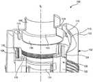
图1是根据一个实施方式的过滤器组件的一部分的侧视横截面图。1 is a side cross-sectional view of a portion of a filter assembly according to one embodiment.
图2是根据一个实施方式的图1的过滤器组件的壳体的仰视图。FIG. 2 is a bottom view of the housing of the filter assembly of FIG. 1 according to one embodiment.
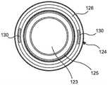
图3是根据一个实施方式的图1的过滤器组件的过滤器元件的俯视图。3 is a top view of a filter element of the filter assembly of FIG. 1 according to one embodiment.
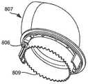
图4是根据另一实施方式的用于过滤器组件的壳体的仰视图。4 is a bottom view of a housing for a filter assembly according to another embodiment.
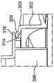
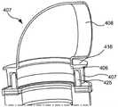
图5是根据一个实施方式的被构造成联接到图4的壳体的出口导管的立体图。5 is a perspective view of an outlet conduit configured to be coupled to the housing of FIG. 4, according to one embodiment.
图6A是图4的壳体的另一仰视图;图6B是沿图6A中的线A-A截取的图6A 的壳体的第一侧视横截面图;以及图6C是沿图6A中的线B-B截取的图6A的壳体的第二侧视横截面图。6A is another bottom view of the housing of FIG. 4; FIG. 6B is a first side cross-sectional view of the housing of FIG. 6A taken along line A-A in FIG. 6A; and FIG. 6C is along line A-A in FIG. 6A A second side cross-sectional view of the housing of Figure 6A taken B-B.
图7是图4的壳体的又一侧视横截面图。FIG. 7 is a further side cross-sectional view of the housing of FIG. 4 .
图8是根据一个实施方式的过滤器组件的分解图。8 is an exploded view of a filter assembly according to one embodiment.
图9A是图8的过滤器组件的出口导管的立体图;图9B是图8的壳体的仰视图,其中出口导管联接到该壳体;图9C是沿图9A中的线A-A截取的图9B的壳体的第一侧视横截面图;以及图9D是沿图9A中的线B-B截取的图9B的壳体的第二侧视横截面图。Figure 9A is a perspective view of the outlet conduit of the filter assembly of Figure 8; Figure 9B is a bottom view of the housing of Figure 8 with the outlet conduit coupled to the housing; Figure 9C is Figure 9B taken along line A-A in Figure 9A and FIG. 9D is a second side cross-sectional view of the housing of FIG. 9B taken along line B-B in FIG. 9A .
图10A是根据一个实施方式的包括在图8的过滤器组件中的过滤器元件的立体图,图10B是该过滤器元件的俯视图。10A is a perspective view of a filter element included in the filter assembly of FIG. 8, and FIG. 10B is a top view of the filter element, according to one embodiment.
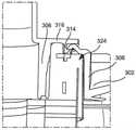
图11是图8的过滤器组件的出口导管的一部分的侧视横截面图,该出口导管联接到图10A至图10B的过滤器元件的端盖。11 is a side cross-sectional view of a portion of the outlet conduit of the filter assembly of FIG. 8 coupled to the end cap of the filter element of FIGS. 10A-10B .
图12是根据另一实施方式的过滤器元件的端盖的俯视立体图。12 is a top perspective view of an end cap of a filter element according to another embodiment.
图13A至图13B是联接到图12的端盖的出口导管的横截面图。13A-13B are cross-sectional views of an outlet conduit coupled to the end cap of FIG. 12 .
图14是根据又一实施方式的过滤器元件的立体图。14 is a perspective view of a filter element according to yet another embodiment.
图15A是根据再一实施方式的出口导管的仰视图;图15B是次过滤器元件的俯视图,该次过滤器元件可定位在主过滤器元件内并与图15A的出口导管的表面形成密封。Figure 15A is a bottom view of an outlet conduit according to yet another embodiment; Figure 15B is a top view of a secondary filter element that can be positioned within the primary filter element and form a seal with the surface of the outlet conduit of Figure 15A.
图16A至图16F是出口导管的各种实施方式的各种视图。16A-16F are various views of various embodiments of an outlet conduit.
在以下详细描述中参考附图。在附图中,除非上下文另有规定,否则类似的符号通常标识类似的部件。在详细描述、附图和权利要求中描述的说明性实现不意味着限制。在不脱离本文所呈现的主题的精神或范围的情况下,可以利用其它实现,并且可以进行其它改变。将容易理解的是,如本文中一般性描述的以及在附图中示出的本公开的各个方面可以以各种各样的不同构造来布置、替换、组合和设计,所有这些都被明确地设想并且构成本公开的一部分。Reference is made to the accompanying drawings in the following detailed description. In the drawings, similar symbols typically identify similar components, unless context dictates otherwise. The illustrative implementations described in the detailed description, drawings, and claims are not meant to be limiting. Other implementations may be utilized, and other changes may be made, without departing from the spirit or scope of the subject matter presented herein. It will be readily appreciated that the various aspects of the present disclosure, as generally described herein and illustrated in the accompanying drawings, may be arranged, substituted, combined and designed in a wide variety of different configurations, all expressly It is contemplated and constitutes a part of this disclosure.
具体实施方式Detailed ways
本文描述的实施方式总体上涉及过滤器组件,该过滤器组件包括限定出口的壳体和穿过出口定位的出口管。出口管可以是椭圆形的,但是包括圆形肋,该圆形肋卡扣配合到限定在壳体的圆形开口中的突出部上,用于将出口管联接到该突出部。其它实施方式涉及限定在壳体的顶部中的凸耳,这些凸耳被构造成插入到限定在过滤器元件的端盖中的对应的槽中,以便于对准以及防止伪造过滤器元件插入到壳体中并与壳体一起使用。Embodiments described herein generally relate to filter assemblies that include a housing defining an outlet and an outlet tube positioned through the outlet. The outlet tube may be oval in shape, but includes a circular rib that snap-fits onto a projection defined in a circular opening in the housing for coupling the outlet tube to the projection. Other embodiments relate to lugs defined in the top of the housing that are configured to be inserted into corresponding slots defined in the end caps of the filter elements to facilitate alignment and prevent insertion of counterfeit filter elements into the filter element. in and with the housing.
本文所述的过滤器组件的实施方式可提供一个或多个益处,包括例如:(1)通过在壳体上设置对应于形成在真正的过滤器元件中的槽的凸耳来防止伪造的过滤器插入到过滤器组件的壳体中;(2)提供椭圆形出口管,所述椭圆形出口管被构造成与限定对应椭圆形开口的真正的过滤器元件接合,从而提供进一步保护以防止伪造的过滤器元件与过滤器组件一起使用;以及(3)提供围绕椭圆形出口管的圆形肋,从而允许出口管相对于壳体的出口以任何合适的径向角度定向。Embodiments of filter assemblies described herein may provide one or more benefits, including, for example: (1) Preventing counterfeit filtering by providing lugs on the housing that correspond to grooves formed in genuine filter elements The filter is inserted into the housing of the filter assembly; (2) an oval outlet tube is provided that is configured to engage with a genuine filter element defining a corresponding oval opening, thereby providing further protection against counterfeiting and (3) providing a circular rib around the elliptical outlet tube, allowing the outlet tube to be oriented at any suitable radial angle relative to the outlet of the housing.
图1是根据一个实施方式的过滤器组件100的一部分的侧视横截面图。过滤器组件100包括限定内部容积的壳体102,过滤器元件120定位在该壳体102内。壳体102 包括入口112,该入口112被切向地限定在壳体102的侧壁103上并且被构造成接收流体(例如,空气、空气/燃料混合物、燃料、润滑剂等)。壳体102可以是如图1 至图2所示的具有圆形横截面的圆柱形形状。在其它实施方式中,壳体102可以具有任何合适的横截面形状,例如正方形、矩形、椭圆形、多边形或其它横截面形状。1 is a side cross-sectional view of a portion of a
壳体102包括顶部104,该顶部104联接到侧壁103的端部并限定轴向出口105。出口弯管108从顶部104的外表面轴向延伸远离壳体102。出口管106从顶部104的内表面轴向延伸到壳体102中。The
现在还参照图3,过滤器元件120定位在由壳体102限定的内部容积内。过滤器元件120包括过滤器介质122,该过滤器介质122限定穿过其中的轴向通道123。过滤器介质122可被构造成当流体从过滤器介质122的外表面和壳体102之间的容积径向地穿过过滤器介质122流入通道123(例如,中心通道)中时过滤流体。第一端盖 124联接到过滤器介质的靠近顶部104的第一端。第一端盖124限定第一端盖开口 125,该第一端盖开口125具有对应于出口弯管108的外径或横截面的直径或横截面,并且被构造成在其中接收出口管106的至少一部分,使得出口弯管108延伸到第一端盖开口125中。出口管106可以与第一端盖124的第一端盖开口125的边缘形成流体密封,以便在被过滤的流体从通道123穿过出口管106和出口弯管108流出壳体102 时使泄漏最小化。例如,出口管106的外横截面尺寸(例如,直径)可以对应于第一端盖开口125的内横截面尺寸(例如,直径),以便与第一端盖开口125的内径向表面形成流体密封。Referring now also to FIG. 3 , the
过滤器介质122包括具有预定孔尺寸的多孔材料,并且被构造成从流过其中的流体过滤颗粒物质。在特定实施方式中,过滤器介质122可包括具有酚醛树脂的纤维素片。在一些实施方式中,过滤器介质122或本文所述的任何其它过滤器介质可包括四面体介质、槽纹过滤器介质、波纹过滤器介质、秸秆介质或它们的变型。Moy等人于2011年10月14日提交并于2013年3月19日授权的题为“PLEATED FILTER ELEMENT WITH TAPERING BEND LINES(带有锥形弯折线的褶皱过滤器元件)”的美国专利No.8,397,920转让给了康明斯过滤工业生产股份有限公司(Cummins Filtration IP Inc),该专利为了全面目的通过引用整体并入本文,其描述了四面体过滤器介质。四面体过滤器介质的一些构造包括多个入口四面体流动通道和多个出口四面体流动通道。入口四面体并入过滤材料的中心部分,从而在空气穿过过滤器介质之前允许空气在入口四面体通道之间轴向交叉流动。这种布置在介质的上游侧提供了额外的灰尘负载,这增加了过滤能力。在特定实施方式中,过滤器介质122可包括褶皱过滤器介质。The
在一些实施方式中,至少一个凸耳可从顶部104轴向延伸到由壳体102限定的内部容积中,并且第一端盖124可限定至少一个槽,该至少一个槽对应于至少一个凸耳并且被构造成当过滤器元件120设置在壳体102中时接收对应的凸耳。例如,如图1 和图2所示,一对凸耳110从顶部104轴向延伸到壳体102中。该对凸耳110彼此相对地定位在出口105的两侧。第一端盖124限定了被构造成接收凸耳110的对应的槽 130。这可以便于将过滤器元件120正确地定位在壳体内并且防止将伪造的过滤器元件定位在壳体102中。在一些实施方式中,第一端盖124可由聚合物材料形成,例如聚氨酯,并且槽130可限定在聚合物材料中。在其它实施方式中,环形构件126可嵌入在聚合物材料内,并且槽130可以限定在环形构件126内。In some embodiments, the at least one lug can extend axially from the top 104 into the interior volume defined by the
在一些实施方式中,过滤器组件的壳体可以包括出口导管,该出口导管包括非圆形出口管,并且该出口导管可移除地联接到过滤器组件的壳体。现在参考图4至图7,示出了根据一个实施方式的用于过滤器组件(例如,本文所述的任何过滤器组件)的壳体202。壳体202包括限定出口205的顶部204。出口205可限定圆形横截面。壳体突出部209从出口205的内边缘201径向向内延伸。在一些实施方式中,壳体突出部209可包括具有定位成远离壳体202的顶点211的弓形构件。壳体202还限定了在壳体202的侧壁203上切向地限定的入口212,该入口212从顶部204轴向地延伸(图 7)。In some embodiments, the housing of the filter assembly can include an outlet conduit that includes a non-circular outlet tube, and the outlet conduit is removably coupled to the housing of the filter assembly. Referring now to FIGS. 4-7 , a
一对凸耳210从壳体202的顶部204轴向延伸到由壳体202限定的内部容积中。该对凸耳210彼此相对地定位在出口205的两侧,并且被构造成如本文先前所述那样插入到过滤器元件中的对应的槽(例如,过滤器元件120的槽130)中。A pair of
出口导管207联接到壳体202。出口导管207包括出口弯管208和从出口管206 朝向壳体202轴向延伸的出口管206。出口管206可以限定椭圆形横截面。出口管206 被构造成穿过出口205定位在壳体202内,并且出口弯管208远离壳体202延伸。肋 214靠近出口弯管208从出口管206的外表面径向延伸出,并且围绕出口管206周向地设置。当出口管206定位成穿过出口205时,肋214接合壳体突出部209,以便将出口管206联接(例如卡扣配合)到出口205。在一些实施方式中,出口205具有圆形形状,并且肋214的外周也限定对应于出口205的形状的圆形形状。
出口导管207还可包括靠近出口管206从出口弯管208或从出口弯管208和出口管206的界面径向向外延伸的周向凸缘216。凸缘216可以具有比肋214的径向长度更长的径向长度。凸缘216可以被构造成用作止动件,以限制出口管206穿过出口 205插入到壳体202中的插入距离。例如,一旦肋214横穿过壳体突出部209,凸缘 216就可接触壳体突出部209的与肋214卡扣配合的表面相反的表面。因此,壳体突出部209可以定位在肋214和凸缘216之间。这样,凸缘216可以防止出口弯管208 进一步插入到壳体202中,并且可以与肋214协作地将出口导管207固定到壳体202。在一些实施方式中,凸缘216可以被构造成与肋214相对地接触壳体突出部(例如,壳体突出部209的顶点211),以便与壳体突出部209形成轴向密封。The
在一些实施方式中,设置在壳体202中的过滤器元件(例如,过滤器元件120) 的第一端盖(例如,第一端盖124)的第一端盖开口(例如,第一端盖开口125)限定第一非圆形形状。在这样的实施方式中,出口管206还限定了对应于第一非圆形形状的第二非圆形横截面形状。在一些实施方式中,第一非圆形形状和第二非圆形横截面形状中的每一个可以包括椭圆形。例如,如图6A至图6C所示,出口管206限定了椭圆形横截面。然而,肋214的外周限定圆形横截面,使得在由出口管206限定的椭圆的长轴处出口管206的外表面与肋214的外边缘之间的第一距离D1大于在该椭圆的短轴处出口管206的外表面与肋214的的外边缘之间的第二距离D2。因此,出口管206可以相对于出口205以任何角度定向穿过出口205定位。这可以简化过滤器组件的组装并降低制造成本。In some embodiments, a first end cap opening (eg, a first end cap) of a first end cap (eg, first end cap 124 ) of a filter element (eg, filter element 120 ) disposed in
图8是根据一个实施方式的过滤器组件300的分解图。过滤器组件300包括限定入口312的壳体302和联接到壳体302的第一端的壳体基部303。主过滤器元件320 定位在壳体302的内部容积内。主过滤器元件320包括主过滤器介质322和远离壳体基部350联接到主过滤器介质322的第一端盖324。第一端盖324限定如本文先前所述的非圆形第一端盖开口325(例如,椭圆形开口) 。FIG. 8 is an exploded view of
次过滤器元件340定位在穿过主过滤器元件320限定的轴向通道内,并可用作安全过滤器,以移除在被过滤器元件320过滤之后可能留在流体中的任何颗粒。次过滤器元件340包括设置在所述轴向通道内的次过滤器介质342以及联接到次过滤器介质 342的次过滤器介质端盖344。The
现在还参照图9A至图9D,出口导管307联接到壳体302。出口导管307包括朝向壳体302延伸并被构造成设置在第一端盖开口325内的出口管306以及延伸远离壳体302的出口弯管308。出口管306具有椭圆形横截面。周向凸缘316从出口管306 和出口弯管308的界面附近径向延伸。一对凸耳310从凸缘316朝向壳体302轴向延伸。肋314也从凸缘316朝向壳体302轴向延伸,并且被构造成接合从限定在壳体 302中的开口的边缘303向内延伸的壳体突出部309,以便将出口导管307卡扣配合到壳体302,如本文先前所述。次过滤器介质端盖344设置在第一端盖开口325内,位于出口管306的径向内侧。在一些实施方式中,次过滤器介质端盖344可具有对应于出口管306的第二非圆形形状的外横截面形状。Referring now also to FIGS. 9A-9D ,
图10A是过滤器元件320的立体图,图10B是过滤器元件320的俯视图。一对槽330限定在过滤器元件320的第一端盖324中,并且对应于从凸缘316朝向过滤器元件320延伸的该对凸耳310。在一些实施方式中,第一端盖324可由聚合物材料(例如聚氨酯)形成,该第一端盖324具有嵌入其中(例如在第一端盖324的模制过程期间)的环326(例如塑料或金属环)。槽330可以限定在环326中。FIG. 10A is a perspective view of
图11是联接到第一端盖324的出口导管307的一部分的侧视横截面图。第一端盖324定位在出口管306、壳体302的侧壁、凸缘316的面向第一端盖324的下表面和肋314的内表面之间。这样,第一端盖324与出口管306和肋314的内表面形成主要径向密封,并且还与凸缘316的下表面形成主要轴向密封。FIG. 11 is a side cross-sectional view of a portion of
现在还参照图12至图13B,图12是根据另一实施方式的过滤器元件420的端盖 424的俯视立体图。端盖424包括从端盖424的第一表面朝向出口导管407突出的联接构件425。图13A至图13B是联接到端盖424的出口导管407的横截面图。出口导管407包括出口弯管408和从凸缘416朝向过滤器元件420延伸的出口管406。出口导管407还包括从凸缘416朝向过滤器元件420轴向延伸并且位于外肋409的径向外侧的外肋409。联接构件425被构造成定位在出口管406和外肋409之间,并且例如经由摩擦配合固定在其中,以便与凸缘416形成轴向密封,并且与出口管406的外表面形成径向密封。Referring now also to Figures 12-13B, Figure 12 is a top perspective view of an
图14是根据又一实施方式的过滤器元件520的立体图。过滤器元件520包括过滤器介质522和端盖524。一对凹口530限定在端盖524中,该端盖524被构造成接收从过滤器组件的壳体的顶部或从出口导管朝向过滤器元件520延伸的一对凸耳(例如,凸耳110、210、310或410),如本文先前所述。14 is a perspective view of a
图15A是根据又一实施方式的出口导管607的仰视图。出口导管607包括出口弯管608。如图15A所示,出口导管607还包括从出口导管607的径向凸缘616轴向延伸的外管606。外管606具有椭圆形横截面,并可被构造成与限定在主过滤器介质或外过滤器介质的端盖中的椭圆形开口接合。出口导管607还包括内管609,该内管 609从径向凸缘616轴向延伸并且定位在外管606的径向内侧。内管609限定圆形横截面,并且被构造成接合定位在主过滤器元件内的次过滤器元件的圆形次过滤器介质端盖。例如,图15B是可基本上类似于本文先前所述的次过滤器元件340的次过滤器元件640的俯视图。次过滤器元件640可包括次过滤器介质(例如,次过滤器介质 642),该次过滤器介质具有联接到其的次过滤器介质端盖644。次过滤器元件640 可定位在主过滤器元件内,次过滤器介质端盖644可定位在主过滤器介质的第一端盖的第一端盖开口内,使得内管609与次过滤器介质端盖644的径向外表面形成密封。Figure 15A is a bottom view of an
虽然本文所述的各种实施方式包括出口导管的具有椭圆形横截面的出口管,但是在各种实施方式中,出口导管的出口管可以具有任何其它合适的非圆形横截面。例如,图16A是根据一个实施方式的包括具有十二边形横截面的出口管706的出口导管707 的仰视图。图16B是根据另一实施方式的出口导管807的仰视立体图。出口导管807 包括出口管806,该出口管806包括限定在出口管806的轴向边缘上的多个凹槽。图 16C是根据又一实施方式的出口导管907的仰视图,该出口导管包括具有带圆角的方形横截面的出口管806。图16D是根据又一实施方式的出口导管1007的仰视图,该出口导管包括限定八边形横截面的出口管1006。图16E是根据又一实施方式的出口导管1107的仰视图,该出口导管包括限定六边形横截面的出口管1106。图16F是根据又一实施方式的出口导管1207的仰视图,该出口导管包括外接在多边形外支撑管中的圆形出口管1206。While the various embodiments described herein include an outlet tube having an oval cross-section of the outlet conduit, in various embodiments, the outlet tube of the outlet conduit may have any other suitable non-circular cross-section. For example, Figure 16A is a bottom view of an
如本文所用,单数形式“一”、“一个”和“该”包括复数指代物,除非上下文另外明确指出。因此,例如,术语“构件”旨在表示单个构件或构件的组合,“材料”旨在表示一种或多种材料或其组合。As used herein, the singular forms "a," "an," and "the" include plural referents unless the context clearly dictates otherwise. Thus, for example, the term "member" is intended to refer to a single member or combination of members, and "material" is intended to refer to one or more materials or a combination thereof.
这里使用的术语“联接”等是指两个构件直接或间接地彼此连接。这种连接可以是固定的(例如,永久的)或可移动的(例如,可移除的或可释放的)。这种连接可以利用两个构件或两个构件和任何附加的中间构件彼此一体地形成为单个整体来实现,或者利用两个构件或两个构件和任何附加的中间构件彼此附接来实现。As used herein, the terms "coupled" and the like mean that two members are directly or indirectly connected to each other. Such connections may be fixed (eg, permanent) or movable (eg, removable or releasable). This connection may be achieved with the two members or the two members and any additional intermediate members being integrally formed with each other as a single unit, or with the two members or the two members and any additional intermediate members attached to each other.
重要的是注意到,各种示例性实施方式的构造和布置仅是说明性的。尽管在本公开中仅详细描述了几个实施方式,但是阅读本公开的本领域技术人员将容易理解,在本质上不脱离本文所述主题的新颖教导和优点的情况下,许多修改是可能的(例如,各种元件的大小、尺寸、结构、形状和比例的变化;参数值、安装布置;材料、颜色、定向的使用等)。另外,应当理解,如本领域普通技术人员将理解的,来自本文公开的一个实施方式的特征可以与本文公开的其它实施方式的特征组合。在不脱离本申请的范围的情况下,也可在各种示例性实施方式的设计、操作条件和布置方面作出其它替代、修改、改变和省略。It is important to note that the construction and arrangement of the various exemplary embodiments are illustrative only. Although only a few embodiments have been described in detail in this disclosure, those skilled in the art who read this disclosure will readily appreciate that many modifications are possible without materially departing from the novel teachings and advantages of the subject matter described herein (eg, variations in size, dimension, configuration, shape, and proportions of various elements; parameter values, mounting arrangements; use of materials, colors, orientations, etc.). Additionally, it should be understood that features from one embodiment disclosed herein may be combined with features of other embodiments disclosed herein, as will be understood by one of ordinary skill in the art. Other substitutions, modifications, changes and omissions may also be made in the design, operating conditions and arrangement of the various exemplary embodiments without departing from the scope of the present application.
虽然本说明书包含许多具体实现细节,但是这些不应被解释为对任何实施方式的范围或者可以要求保护的范围的限制,而是应被解释为对具体实施方式的具体实现所特有的特征的描述。在本说明书中在单独实现的上下文中描述的某些特征也可以在单个实现中组合地实现。相反,在单个实现的上下文中描述的各种特征也可以在多个实现中单独地或以任何合适的子组合实现。此外,尽管特征可以在上面被描述为在某些组合中起作用并且甚至最初被这样要求保护,但是来自所要求保护的组合的一个或多个特征在一些情况下可以从该组合中被去除,并且所要求保护的组合可以针对子组合或子组合的变型。While this specification contains many implementation-specific details, these should not be construed as limitations on the scope of any implementation, or what may be claimed, but rather as descriptions of features specific to particular implementations of specific implementations . Certain features that are described in this specification in the context of separate implementations can also be implemented in combination in a single implementation. Conversely, various features that are described in the context of a single implementation can also be implemented in multiple implementations separately or in any suitable subcombination. Furthermore, although features may be described above as functioning in certain combinations and even originally claimed as such, one or more features from a claimed combination may in some cases be removed from the combination, And claimed combinations may be directed to subcombinations or variations of subcombinations.
Claims (21)
Applications Claiming Priority (3)
| Application Number | Priority Date | Filing Date | Title |
|---|---|---|---|
| IN201841020376 | 2018-05-31 | ||
| IN201841020376 | 2018-05-31 | ||
| PCT/US2019/033759WO2019231820A1 (en) | 2018-05-31 | 2019-05-23 | Filter assembly including a removable outlet conduit |
Publications (2)
| Publication Number | Publication Date |
|---|---|
| CN112154023A CN112154023A (en) | 2020-12-29 |
| CN112154023Btrue CN112154023B (en) | 2022-04-26 |
Family
ID=68697130
Family Applications (1)
| Application Number | Title | Priority Date | Filing Date |
|---|---|---|---|
| CN201980033312.3AActiveCN112154023B (en) | 2018-05-31 | 2019-05-23 | Filter assembly including removable outlet conduit |
Country Status (4)
| Country | Link |
|---|---|
| US (1) | US12115481B2 (en) |
| CN (1) | CN112154023B (en) |
| DE (1) | DE112019002755T5 (en) |
| WO (1) | WO2019231820A1 (en) |
Families Citing this family (2)
| Publication number | Priority date | Publication date | Assignee | Title |
|---|---|---|---|---|
| DE102020128911A1 (en)* | 2020-11-03 | 2022-05-05 | Mann+Hummel Gmbh | Filter system and filter element |
| US12397252B2 (en)* | 2021-04-21 | 2025-08-26 | Donaldson Company, Inc. | Filter housing with drop out chamber and methods |
Citations (3)
| Publication number | Priority date | Publication date | Assignee | Title |
|---|---|---|---|---|
| US6261445B1 (en)* | 1997-04-16 | 2001-07-17 | Earl Roger Singleton | Temporary silt guard for sewer inlet |
| CN105545551A (en)* | 2008-09-24 | 2016-05-04 | 康明斯过滤Ip公司 | Fluid sensor module for filter assembly and filter assembly |
| CN107435576A (en)* | 2016-05-27 | 2017-12-05 | 罗伯特·博世有限公司 | Integrated exhaust gas aftertreatment system |
Family Cites Families (103)
| Publication number | Priority date | Publication date | Assignee | Title |
|---|---|---|---|---|
| GB272544A (en) | 1926-06-11 | 1927-09-29 | Beth Ag Maschf | Improvements in filter bag cleaning devices for air filters |
| DE1302439B (en) | 1962-09-10 | 1971-04-15 | ||
| US3350855A (en) | 1965-10-05 | 1967-11-07 | American Air Filter Co | Roll-type filter construction |
| GB1104643A (en) | 1966-03-23 | 1968-02-28 | Fram Filters Ltd | Improvements in or relating to air filters |
| US3350856A (en) | 1966-04-25 | 1967-11-07 | American Air Filter Co | Media support arrangement for rolltype filter apparatus |
| US3668842A (en) | 1970-03-20 | 1972-06-13 | Singer Co | Vacuum cleaner and exhaust housing |
| US3636681A (en) | 1970-03-20 | 1972-01-25 | Singer Co | Vacuum cleaner filter assembly |
| CH577664A5 (en) | 1974-02-15 | 1976-07-15 | Luwa Ag | |
| US4141700A (en) | 1976-09-27 | 1979-02-27 | Air Refiner, Inc. | Fin structure for air pre-cleaner |
| US4698985A (en) | 1986-03-17 | 1987-10-13 | General Motors Corporation | Accumulator-dehydrator assembly for an air conditioning system |
| US4967443A (en) | 1989-01-09 | 1990-11-06 | Black & Decker, Inc. | Filter assembly for a vacuum cleaner |
| DE4018046C2 (en) | 1990-06-06 | 1993-10-07 | Icleen Entwicklung Vertrieb | Variable air filter system for convection and ventilation air flows |
| DE4241586C1 (en) | 1992-12-10 | 1994-01-27 | Mann & Hummel Filter | Air filter |
| US5547480A (en)* | 1994-01-21 | 1996-08-20 | Donaldson Company, Inc. | Cylindrical air filter with radially directed seal |
| JP3468436B2 (en)* | 1994-09-22 | 2003-11-17 | 豊田紡織株式会社 | Resin air cleaner |
| US5938804A (en) | 1994-11-23 | 1999-08-17 | Donaldson Company, Inc. | Reverse flow air filter arrangement and method |
| DE19623078A1 (en) | 1996-04-26 | 1998-11-19 | Hubert K Block | Table-top bio-active air filter for e.g. offices |
| AU4954797A (en) | 1996-11-14 | 1998-06-03 | Mcleod Russel Holdings Plc | Air filter |
| US5800581A (en)* | 1997-04-07 | 1998-09-01 | Air-Maze Corporation | Air cleaner having filter element integrally formed with housing end cap |
| US5803939A (en) | 1997-04-24 | 1998-09-08 | Alanco Environmental Resources Corp. | Industrial dust collector and method for its use |
| US5846302A (en) | 1997-04-24 | 1998-12-08 | Aqua-Air Technologies, Inc. | Electrostatic air filter device |
| US5865863A (en)* | 1997-05-08 | 1999-02-02 | Siemens Electric Limited | Combined air cleaner-resonator |
| US6051042A (en)* | 1997-09-12 | 2000-04-18 | Donaldson Company, Inc. | Air cleaner assembly |
| JP3849284B2 (en) | 1998-02-24 | 2006-11-22 | 株式会社富士通ゼネラル | Air filter air filter mounting structure |
| US6105576A (en) | 1998-10-14 | 2000-08-22 | Enternet Medical, Inc. | Apparatus for treating respiratory gases including liquid trap |
| US6299661B1 (en)* | 1999-05-12 | 2001-10-09 | Siemens Canada Limited | Twist fit connection for air cleaners |
| US6167862B1 (en)* | 1999-05-12 | 2001-01-02 | Siemens Canada Limited | Air cleaner system |
| DE50014997D1 (en)* | 1999-09-09 | 2008-04-10 | Hengst Gmbh & Co Kg | FLUID FILTER WITH HOUSING FAILED DOMESTIC |
| DE19963088B4 (en) | 1999-12-24 | 2014-02-13 | Mann + Hummel Gmbh | Plate-shaped filter insert with end edge reinforcement |
| US6949189B2 (en)* | 2000-04-20 | 2005-09-27 | Cuno Incorporated | Keyed filter assembly |
| US6723148B2 (en) | 2000-12-08 | 2004-04-20 | Siemens Vdo Automotive, Inc. | Moldable twist lock snap fit design for plastic air cleaner |
| US6569219B1 (en)* | 2001-05-11 | 2003-05-27 | Nelson Industries, Inc. | Air filter with serviceable filter media |
| FR2827642B1 (en) | 2001-07-19 | 2004-01-30 | Mark Iv Systemes Moteurs Sa | AIR FILTER ASSEMBLY FOR INTERNAL COMBUSTION ENGINE VEHICLE |
| US6966940B2 (en)* | 2002-04-04 | 2005-11-22 | Donaldson Company, Inc. | Air filter cartridge |
| US20030188520A1 (en) | 2002-04-05 | 2003-10-09 | Paul Boulva | Air filter system for a free-standing air blowing fan |
| JP2003326123A (en) | 2002-05-09 | 2003-11-18 | Matsushita Electric Ind Co Ltd | Air filter and blower using the same |
| US6797042B2 (en) | 2002-06-21 | 2004-09-28 | Pyramid Air Solutions, Inc. | Pyramid air cleaner |
| US6752846B2 (en) | 2002-07-18 | 2004-06-22 | Kohler Co. | Panel type air filter element with integral baffle |
| CN100406102C (en) | 2002-10-28 | 2008-07-30 | 唐纳森公司 | Air cleaner, replaceable filter cartridge and method of making the same |
| JP4282435B2 (en) | 2002-12-25 | 2009-06-24 | 三洋電機株式会社 | Air conditioner |
| US7128771B2 (en) | 2003-06-25 | 2006-10-31 | Total Filtration Manufacturing | Air filter retaining system |
| US7311748B2 (en) | 2004-03-02 | 2007-12-25 | Parker-Hannifin Corporation | Air filter assembly system and method |
| EP2243536B1 (en) | 2004-06-14 | 2013-11-20 | Donaldson Company, Inc. | Air filter arrangement and cartridge |
| US7828870B1 (en) | 2004-11-24 | 2010-11-09 | Cummins Filtration Ip, Inc. | Filter assembly with cost effective seal |
| US7413588B2 (en) | 2004-11-24 | 2008-08-19 | Fleetguard, Inc. | High efficiency, low restriction, cost effective filter |
| US7491253B2 (en) | 2005-05-31 | 2009-02-17 | Aerospace Filtrations Systems, Inc. | Engine intake system with accessible, interchangeable air filters |
| DE102005031501B4 (en) | 2005-07-06 | 2021-12-09 | Andreas Stihl Ag & Co. Kg | Air filter |
| US7959714B2 (en) | 2007-11-15 | 2011-06-14 | Cummins Filtration Ip, Inc. | Authorized filter servicing and replacement |
| US7815705B2 (en) | 2005-10-19 | 2010-10-19 | Baldwin Filters, Inc. | Air filter with composite end cap |
| EP2664372A1 (en)* | 2006-10-06 | 2013-11-20 | Donaldson Company, Inc. | Air cleaner, replaceable filter cartridges, and methods |
| US7867311B1 (en) | 2006-11-16 | 2011-01-11 | Cummins Filtration Ip, Inc. | Filter assembly with trapped auxiliary flow component |
| US7597735B2 (en) | 2006-12-21 | 2009-10-06 | Cummins Filtration Ip Inc. | Apparatus and system for uniform sealing force in an air filter assembly |
| DE102007006103B4 (en) | 2007-02-02 | 2012-06-06 | Carl Freudenberg Kg | Frame and cassette filter |
| WO2009106588A1 (en)* | 2008-02-26 | 2009-09-03 | Mann+Hummel Gmbh | Filter device, in particular air filter for an internal combustion engine |
| US7662283B2 (en) | 2008-03-21 | 2010-02-16 | Pentair Filtration, Inc. | Modular drinking water filtration system with locking arrangement to assure filter cartridge compatibility |
| US20090236277A1 (en) | 2008-03-21 | 2009-09-24 | Pentair Filtration, Inc. | Modular Drinking Water Filtration System with Internal Sealing Between Valve Spindle and Head |
| US7695619B2 (en) | 2008-03-21 | 2010-04-13 | Pentair Filtration, Inc. | Modular drinking water filtration system with adapter rings for replaceable cartridges to assure proper fit |
| US20090236272A1 (en) | 2008-03-21 | 2009-09-24 | Pentair Filtration, Inc. | Modular Drinking Water Filtration System with Keyed Attachment of Filter Head to Mounting Bracket and Modular Back Plates |
| JP5694637B2 (en) | 2008-06-02 | 2015-04-01 | 進和テック株式会社 | Auto-regenerative air filter |
| US7959700B2 (en) | 2008-07-01 | 2011-06-14 | Mann + Hummel Gmbh | Filter orientation ribs |
| GB0812457D0 (en) | 2008-07-08 | 2008-08-13 | Parker Hannifin U K Ltd | A Filter |
| US8097061B2 (en)* | 2008-09-18 | 2012-01-17 | Cummins Filtration Ip, Inc. | Elliptical seal interface for filter assembly |
| CN201301768Y (en) | 2008-10-27 | 2009-09-02 | 蚌埠市昊业滤清器有限公司 | Air filter element |
| DE102008054878B4 (en) | 2008-12-18 | 2010-12-23 | Kaeser Kompressoren Gmbh | Filter element and compressed air filter for separating foreign substances from a compressed air flow |
| US8142537B2 (en) | 2009-03-17 | 2012-03-27 | Mann + Hummel Gmbh | Support grid and alignment appartus for a filter element and housing |
| US8424153B2 (en) | 2009-03-19 | 2013-04-23 | Bissell Homecare, Inc. | Vacuum cleaner and filters therefor |
| AU2010201003B2 (en) | 2009-03-20 | 2014-05-08 | Bissell Homecare, Inc. | Filter locking arrangement for a vacuum cleaner |
| US7935160B2 (en) | 2009-05-29 | 2011-05-03 | Cummins Filtration Ip, Inc. | Filter assembly with trapped contaminant servicing |
| US8287614B2 (en) | 2009-08-10 | 2012-10-16 | Mann+Hummel Gmbh | Supplemental filter media support insert for an air cleaner |
| CA2695299C (en)* | 2009-08-21 | 2017-07-11 | Roger P. Reid | Keyed system for connection of filter to filter holder |
| DE102009041298A1 (en) | 2009-09-15 | 2011-03-24 | Hengst Gmbh & Co. Kg | Fuel filter of an internal combustion engine |
| CN101811113B (en) | 2010-04-02 | 2012-05-09 | 蚌埠市昊业滤清器有限公司 | Powder spraying curing automatic production line of case of rotary filter |
| DE102010020727B4 (en) | 2010-05-17 | 2012-01-12 | Mann + Hummel Gmbh | Filter, filter element, mounting housing part of a filter housing and telescopic switching element of a switching device of a releasable latching connection |
| CN201823409U (en) | 2010-09-19 | 2011-05-11 | 北京百年恒丰净化设备安装有限公司 | Air pre-filtration device with replaceable filter medium |
| DE102011011595A1 (en) | 2011-02-17 | 2012-08-23 | Mann + Hummel Gmbh | filter element |
| US8551206B2 (en) | 2011-05-18 | 2013-10-08 | General Electric Company | System and method for securing gas turbine air filters |
| US20130062291A1 (en) | 2011-09-12 | 2013-03-14 | Caterpillar Inc. | Re-Entrainment Reduction Structure For Fluid Filter Assembly |
| CN202284849U (en) | 2011-11-09 | 2012-06-27 | 重庆松芝汽车空调有限公司 | Automotive air conditioning assembly with easily detached air filter screen |
| KR101360098B1 (en) | 2012-03-08 | 2014-02-20 | 김종인 | Air filter frame manufacturing equipment |
| CN203154983U (en) | 2013-01-11 | 2013-08-28 | 广州市尚诚过滤器材有限公司 | Detachable air filter screen |
| BR112015028877A2 (en) | 2013-06-06 | 2017-07-25 | Cummins Filtration Ip Inc | filters and their cartridges |
| WO2015061168A1 (en) | 2013-10-23 | 2015-04-30 | Cummins Filtration Ip, Inc. | Filter with engine integrity protection |
| CN203790746U (en) | 2013-12-03 | 2014-08-27 | 东莞市海莎过滤器有限公司 | Air cartridge filter |
| CN104712861A (en) | 2013-12-17 | 2015-06-17 | 曼胡默尔滤清器(上海)有限公司 | Auxiliary positioning structure for air filtering system pipeline connecting |
| CN103934618B (en) | 2014-05-10 | 2016-03-30 | 蚌埠国威滤清器有限公司 | A kind of air filter weld jig |
| US10226727B2 (en) | 2014-06-03 | 2019-03-12 | Cummins Filtration Ip, Inc. | Filter assembly with cam-lock filter interface |
| CN204035339U (en) | 2014-06-30 | 2014-12-24 | 柳州日高滤清器有限责任公司 | A kind of air cleaner casing flanging die |
| CN105268838B (en) | 2014-06-30 | 2017-03-15 | 柳州日高滤清器有限责任公司 | A kind of air cleaner casing flanging die |
| CN204035337U (en) | 2014-06-30 | 2014-12-24 | 柳州日高滤清器有限责任公司 | A kind of air cleaner casing circular arc flanging die |
| CN203990024U (en)* | 2014-08-29 | 2014-12-10 | 金正日 | False proof water purifier |
| US10087898B2 (en) | 2014-09-26 | 2018-10-02 | Ford Global Technologies Llc | Air filter element assembly for a motor vehicle |
| CN104526989B (en) | 2014-11-12 | 2017-07-07 | 浙江神舟机器人科技有限公司 | A kind of mouth of a river cutter sweep of the interface of air filter for automobile |
| CN204279043U (en) | 2014-12-01 | 2015-04-22 | 中国重汽集团济南动力有限公司 | Sectional shelf-unit installed by a kind of air filter of passenger car device-noise silencer |
| US20160332095A1 (en) | 2015-05-11 | 2016-11-17 | Cummins Filtration Ip, Inc. | Filtration System with Anti Drain Valve and Drain X-Seal |
| US10029198B2 (en)* | 2015-06-25 | 2018-07-24 | Donaldson Company, Inc. | Assemblies; components and filter features thereof; and, methods of use and assembly |
| WO2017053177A1 (en) | 2015-09-24 | 2017-03-30 | 3M Innovative Properties Company | Air filter devices with gap sealing unit |
| US10302049B2 (en) | 2015-12-18 | 2019-05-28 | Mann+Hummel Purolator Filters Llc | Dual bellow filter element with communication channels |
| EP4272855A3 (en)* | 2016-02-12 | 2024-01-03 | Donaldson Company, Inc. | Filter elements and air cleaner assemblies |
| DE102016004315A1 (en) | 2016-04-12 | 2017-10-12 | Mann + Hummel Gmbh | A filter assembly |
| CN205606860U (en) | 2016-04-15 | 2016-09-28 | 深圳创维空调科技有限公司 | Panel motion and have its air conditioner |
| CN106091197B (en) | 2016-07-19 | 2021-09-10 | 江苏风神空调集团股份有限公司 | Column air conditioning system without machine room |
| CN206372619U (en) | 2017-01-11 | 2017-08-04 | 佛冈县粤华空调设备有限公司 | Aluminium frame nylon air cleaner |
| US11460481B2 (en)* | 2019-05-30 | 2022-10-04 | AirFlow Directions, Inc. | Directional differential pressure detector having a differential pressure set point indicator |
- 2019
- 2019-05-23CNCN201980033312.3Apatent/CN112154023B/enactiveActive
- 2019-05-23USUS17/058,345patent/US12115481B2/enactiveActive
- 2019-05-23DEDE112019002755.7Tpatent/DE112019002755T5/enactivePending
- 2019-05-23WOPCT/US2019/033759patent/WO2019231820A1/ennot_activeCeased
Patent Citations (3)
| Publication number | Priority date | Publication date | Assignee | Title |
|---|---|---|---|---|
| US6261445B1 (en)* | 1997-04-16 | 2001-07-17 | Earl Roger Singleton | Temporary silt guard for sewer inlet |
| CN105545551A (en)* | 2008-09-24 | 2016-05-04 | 康明斯过滤Ip公司 | Fluid sensor module for filter assembly and filter assembly |
| CN107435576A (en)* | 2016-05-27 | 2017-12-05 | 罗伯特·博世有限公司 | Integrated exhaust gas aftertreatment system |
Non-Patent Citations (1)
| Title |
|---|
| Polarization independent integrated filter based on a cross-slot waveguide;atthieu Roussey;《Optics express》;20141231;第22卷(第20期);24149-24159* |
Also Published As
| Publication number | Publication date |
|---|---|
| US12115481B2 (en) | 2024-10-15 |
| DE112019002755T5 (en) | 2021-02-18 |
| CN112154023A (en) | 2020-12-29 |
| WO2019231820A1 (en) | 2019-12-05 |
| US20210086118A1 (en) | 2021-03-25 |
Similar Documents
| Publication | Publication Date | Title |
|---|---|---|
| CN102046259B (en) | Spin-on filter with external threads and method | |
| JP4334137B2 (en) | Double filter | |
| US7237682B2 (en) | Filter assembly with slip thread | |
| EP2763779B1 (en) | Filter cartridge assembly | |
| US12263428B2 (en) | Radial seal for spin-on filter | |
| US11607633B2 (en) | Filtration system with automatic drain plug | |
| CN115209974B (en) | Filter arrangement for liquids and method of use | |
| CN112154023B (en) | Filter assembly including removable outlet conduit | |
| EP4274671A1 (en) | Filter assemblies with combined axial and radial sealing | |
| US20210129064A1 (en) | Filter element center tube cage with poke yoke feature | |
| AU2015241509B2 (en) | Filter assembly | |
| JPS5912327B2 (en) | fluid filter | |
| US12017171B2 (en) | Filter element and housing having non-circular cross-sections | |
| CN109843409B (en) | Bowl of filter assembly | |
| US11298640B2 (en) | Expandable threaded adaptor for threadless shell | |
| CN210543733U (en) | Filter assembly and filter element | |
| CN111818982B (en) | System and method for securing a sealing member to a filter assembly | |
| US20250262573A1 (en) | Filter assembly with floating seal interface | |
| EP4342566A1 (en) | Gas filter system | |
| CN116096469A (en) | Filter assembly including separate fuel and water flow paths | |
| WO2021071825A1 (en) | Cartridge endplate with integrated sealing and removal feature | |
| US20160038863A1 (en) | Filter Cartridge With Integral Lock Ring | |
| CN115869696A (en) | Filter element and housing having a first engagement area and a second engagement area | |
| CN119095659A (en) | Filter assembly including oval sealing interface |
Legal Events
| Date | Code | Title | Description |
|---|---|---|---|
| PB01 | Publication | ||
| PB01 | Publication | ||
| SE01 | Entry into force of request for substantive examination | ||
| SE01 | Entry into force of request for substantive examination | ||
| GR01 | Patent grant | ||
| GR01 | Patent grant |