CN112153832B - A rotating shaft mechanism and a foldable mobile terminal - Google Patents
A rotating shaft mechanism and a foldable mobile terminalDownload PDFInfo
- Publication number
- CN112153832B CN112153832BCN201910569633.7ACN201910569633ACN112153832BCN 112153832 BCN112153832 BCN 112153832BCN 201910569633 ACN201910569633 ACN 201910569633ACN 112153832 BCN112153832 BCN 112153832B
- Authority
- CN
- China
- Prior art keywords
- displacement
- assembly
- shaft
- rotating
- accommodating groove
- Prior art date
- Legal status (The legal status is an assumption and is not a legal conclusion. Google has not performed a legal analysis and makes no representation as to the accuracy of the status listed.)
- Active
Links
Images


Classifications
- H—ELECTRICITY
- H05—ELECTRIC TECHNIQUES NOT OTHERWISE PROVIDED FOR
- H05K—PRINTED CIRCUITS; CASINGS OR CONSTRUCTIONAL DETAILS OF ELECTRIC APPARATUS; MANUFACTURE OF ASSEMBLAGES OF ELECTRICAL COMPONENTS
- H05K5/00—Casings, cabinets or drawers for electric apparatus
- H05K5/02—Details
- H05K5/0217—Mechanical details of casings
- H—ELECTRICITY
- H04—ELECTRIC COMMUNICATION TECHNIQUE
- H04M—TELEPHONIC COMMUNICATION
- H04M1/00—Substation equipment, e.g. for use by subscribers
- H04M1/02—Constructional features of telephone sets
- H04M1/0202—Portable telephone sets, e.g. cordless phones, mobile phones or bar type handsets
- H04M1/0206—Portable telephones comprising a plurality of mechanically joined movable body parts, e.g. hinged housings
- H04M1/0208—Portable telephones comprising a plurality of mechanically joined movable body parts, e.g. hinged housings characterized by the relative motions of the body parts
- H04M1/0214—Foldable telephones, i.e. with body parts pivoting to an open position around an axis parallel to the plane they define in closed position
- H04M1/0216—Foldable in one direction, i.e. using a one degree of freedom hinge
- H—ELECTRICITY
- H04—ELECTRIC COMMUNICATION TECHNIQUE
- H04M—TELEPHONIC COMMUNICATION
- H04M1/00—Substation equipment, e.g. for use by subscribers
- H04M1/02—Constructional features of telephone sets
- H04M1/0202—Portable telephone sets, e.g. cordless phones, mobile phones or bar type handsets
- H04M1/026—Details of the structure or mounting of specific components
- H04M1/0266—Details of the structure or mounting of specific components for a display module assembly
- H04M1/0268—Details of the structure or mounting of specific components for a display module assembly including a flexible display panel
Landscapes
- Engineering & Computer Science (AREA)
- Signal Processing (AREA)
- Microelectronics & Electronic Packaging (AREA)
- Telephone Set Structure (AREA)
- Casings For Electric Apparatus (AREA)
- Pivots And Pivotal Connections (AREA)
Abstract
Translated fromChinese
Description
Translated fromChinese技术领域technical field
本申请涉及到终端技术领域,尤其涉及到一种转轴机构及可折叠移动终端。The present application relates to the technical field of terminals, and in particular, to a rotating shaft mechanism and a foldable mobile terminal.
背景技术Background technique
随着柔性显示屏技术的逐渐成熟,促使终端设备的显示方式发生了非常大的变化,可折叠柔性屏手机就是未来手机差异化的一大重要演进方向。由于可折叠手机的显示屏具有可根据不同的使用场景进行显示模式的灵活切换的特点,其必将成为主流设备厂商下代手机开发的主方向。未来,可折叠必将成为终端产品的一大卖点。With the gradual maturity of flexible display technology, the display mode of terminal equipment has undergone great changes. Foldable flexible screen mobile phones are an important evolution direction of mobile phone differentiation in the future. Since the display screen of a foldable mobile phone has the characteristics of flexible switching of display modes according to different usage scenarios, it will definitely become the main direction for the development of next-generation mobile phones by mainstream equipment manufacturers. In the future, foldables will surely become a major selling point of end products.
由于柔性显示屏是可折叠移动终端中的关键部件,在可折叠移动终端折叠模式切换的过程中,若可折叠移动终端的折叠以及展开状态不能保持,可能会使其受外力影响导致柔性显示屏的显示异常。因此,如何实现可折叠移动终端的折叠状态以及展开状态的维持,成为了本领域技术人员亟待解决的一大难题。Since the flexible display screen is a key component in the foldable mobile terminal, during the process of switching the folding mode of the foldable mobile terminal, if the folded and unfolded state of the foldable mobile terminal cannot be maintained, it may be affected by external forces and cause the flexible display screen display is abnormal. Therefore, how to maintain the folded state and the unfolded state of the foldable mobile terminal has become a major problem to be solved urgently by those skilled in the art.
发明内容SUMMARY OF THE INVENTION
本申请实施例提供了一种转轴机构及可折叠移动终端,以实现可折叠移动终端的折叠状态的维持。Embodiments of the present application provide a rotating shaft mechanism and a foldable mobile terminal, so as to maintain the folded state of the foldable mobile terminal.
第一方面,提供了一种转轴机构,该转轴机构可应用于可折叠的移动终端,并且作为移动终端的折叠机构,其中,该转轴机构分别与移动终端的两个壳体固定连接,在移动终端折叠时,两个壳体可绕该转轴机构转动以实现折叠。该转轴机构包括主轴,成对设置于主轴的阻尼组,每对阻尼组沿垂直于主轴的轴线方向分设于主轴的两侧,每个阻尼组包括三个部分,分别为:转动组件、位移组件以及弹性模块,其中,转动组件作为该转轴机构的主动部分可带动位移组件转动,同时位移组件与弹性模块相配合可实现转动组件的转动位的限定。其中,转动组件设置有连接部和支撑部,连接部可与主轴的端部转动连接,支撑部包括用于容置位移组件的第一容置槽,以及用于容置弹性模块的第二容置槽,第一容置槽的延伸方向与第二容置槽的延伸方向垂直,而第一容置槽的延伸方向与主轴的轴线垂直。In a first aspect, a rotating shaft mechanism is provided, which can be applied to a foldable mobile terminal and is used as a folding mechanism of the mobile terminal, wherein the rotating shaft mechanism is respectively fixedly connected with two housings of the mobile terminal, and is moved when moving. When the terminal is folded, the two shells can be rotated around the rotating shaft mechanism to realize folding. The rotating shaft mechanism includes a main shaft and a pair of damping groups arranged on the main shaft. Each pair of damping groups is arranged on both sides of the main shaft along an axis perpendicular to the main shaft. Each damping group includes three parts, namely: a rotating assembly and a displacement assembly. and an elastic module, wherein the rotating component as the active part of the rotating shaft mechanism can drive the displacement component to rotate, and at the same time the displacement component cooperates with the elastic module to realize the limitation of the rotation position of the rotating component. The rotating assembly is provided with a connecting portion and a supporting portion, the connecting portion can be rotatably connected with the end of the main shaft, and the supporting portion includes a first accommodating groove for accommodating the displacement assembly, and a second accommodating groove for accommodating the elastic module. The extending direction of the first accommodating groove is perpendicular to the extending direction of the second accommodating groove, and the extending direction of the first accommodating groove is perpendicular to the axis of the main shaft.
这样,当转动组件用于支撑位移组件时,位移组件的一端与主轴转动连接,位移组件的主体容置于第一容置槽,且其靠近第二容置槽一侧的侧壁设置有多个限位凹槽。在具体设置弹性模块时,弹性模块容置于第二容置槽,包括相抵接的滚珠和弹性结构件,滚珠可沿位移组件靠近第二容置槽的侧壁转动。当包含有该转动组件的可折叠的移动终端的折叠状态改变时,转动组件绕主轴转动,位移组件随之转动,同时滚珠沿位移组件的侧壁滚动,由于位移组件靠近第二容置槽的侧壁具有多个限位凹槽,这样滚珠在滚动的过程中会在弹性结构件的弹力作用下落入限位凹槽,以阻止滚珠继续在位移组件上运动,从而使转动组件停止转动,进而可使移动终端维持在对应的折叠位。In this way, when the rotating assembly is used to support the displacement assembly, one end of the displacement assembly is rotatably connected to the main shaft, the main body of the displacement assembly is accommodated in the first accommodating groove, and the side wall on the side close to the second accommodating groove is provided with multiple limit grooves. When the elastic module is specifically arranged, the elastic module is accommodated in the second accommodating groove, and includes abutting balls and elastic structural members, and the balls can rotate along the side wall of the displacement assembly close to the second accommodating groove. When the folded state of the foldable mobile terminal including the rotating assembly changes, the rotating assembly rotates around the main shaft, the displacement assembly rotates accordingly, and the ball rolls along the sidewall of the displacement assembly. The side wall has a plurality of limit grooves, so that the balls will fall into the limit grooves under the elastic force of the elastic structure during the rolling process, so as to prevent the balls from continuing to move on the displacement component, so as to stop the rotation of the rotating component, and then The mobile terminal can be maintained in the corresponding folded position.
在具体设置第一容置槽和位移组件时,第一容置槽还开设有条形孔,该条形孔的延伸方向与第一容置槽的延伸方向相同,同时位移组件还包括可沿条形孔滑动的滑动部,其中,滑动部可以但不限于为设置于位移组件的圆柱形凸起。在位移组件随转动组件转动的过程中,滑动部限位于条形孔,且可沿条形孔滑动,这样可有效的提高位移组件运动的可靠性。When specifically setting the first accommodating slot and the displacement assembly, the first accommodating slot is also provided with a strip hole, and the extending direction of the strip hole is the same as the extending direction of the first accommodating slot. The sliding part of the strip hole slides, wherein the sliding part can be, but not limited to, a cylindrical protrusion provided on the displacement component. When the displacement component rotates with the rotating component, the sliding portion is limited to the strip-shaped hole and can slide along the strip-shaped hole, which can effectively improve the movement reliability of the displacement component.
在具体实现转动组件与主轴的连接时,主轴包括固定连接的主内轴和主外轴,主外轴的端部设置有连接轴,该连接轴的轴线与主轴的轴线平行;同时,转动组件的连接部具有与连接轴相匹配的连接孔,从而可通过使连接轴穿设于连接孔的方式实现转动组件与主轴的连接。When the connection between the rotating assembly and the main shaft is specifically realized, the main shaft includes a main inner shaft and a main outer shaft that are fixedly connected, the end of the main outer shaft is provided with a connecting shaft, and the axis of the connecting shaft is parallel to the axis of the main shaft; at the same time, the rotating assembly The connecting part of the device has a connecting hole matched with the connecting shaft, so that the connection between the rotating component and the main shaft can be realized by passing the connecting shaft through the connecting hole.
而位移组件在与主轴连接时,主外轴还设置有第三容置槽,主内轴设置有用于露出第三容置槽的开口;位移组件靠近主轴的一端容置于第三容置槽,且与第三容置槽转动连接。When the displacement assembly is connected to the main shaft, the main outer shaft is also provided with a third accommodating groove, and the main inner shaft is provided with an opening for exposing the third accommodating groove; the end of the displacement assembly close to the main shaft is accommodated in the third accommodating groove , and is rotatably connected with the third accommodating groove.
在具体设置位移组件时,主外轴的第三容置槽还具有圆弧面,位移组件靠近主轴的一端具有支撑轴,该支撑轴容置于圆弧面,且可沿圆弧面转动,从而实现位移组件与主轴的转动连接。除此之外,位移组件还可通过铰接或者枢装等方式实现与第三容置槽的转动连接,并且位移组件在转动的过程中,主内轴的开口不会对其造成干涉。When the displacement assembly is specifically arranged, the third accommodating groove of the main outer shaft also has an arc surface, and the end of the displacement assembly close to the main shaft has a support shaft, which is accommodated in the arc surface and can rotate along the arc surface. Thus, the rotational connection between the displacement component and the main shaft is realized. In addition, the displacement assembly can also be pivotally connected to the third accommodating groove by means of hinged or pivoted installation, and during the rotation of the displacement assembly, the opening of the main inner shaft will not interfere with it.
在一个可能的实施方式中,在具体设置阻尼组时,阻尼组可包括一一对应设置的转动组件和位移组件。此时,转动组件还包括设置于第二容置槽远离位移组件一端的挡板,弹性结构件的一端固定于该挡板。In a possible implementation manner, when the damping group is specifically arranged, the damping group may include a rotation component and a displacement component arranged in a one-to-one correspondence. At this time, the rotating assembly further includes a baffle plate disposed at one end of the second accommodating groove away from the displacement assembly, and one end of the elastic structural member is fixed to the baffle plate.
其中,弹性结构件可以但不限于为弹簧,当弹性结构件为弹簧时,为了实现对弹簧的限位,以使其在运动过程中不发生弯折,可以在挡板上设置限位支柱,从而使弹簧套设于限位支柱,其中,弹簧可以为一条,也可以为多条。同时,在该弹簧靠近位移组件的一端还设置有连接板,连接板卡接于第二容置槽的槽壁,从而实现弹簧的固定。此时,滚珠与连接板相抵接,并沿连接板的表面运动,这样可减小弹性结构件与滚珠之间的摩擦,使滚珠的运动更加灵活。Wherein, the elastic structural member can be, but is not limited to, a spring. When the elastic structural member is a spring, in order to limit the position of the spring so that it does not bend during the movement process, a limit strut can be set on the baffle plate. Therefore, the spring is sleeved on the limiting strut, wherein the spring can be one or more than one. At the same time, a connecting plate is also provided at one end of the spring close to the displacement component, and the connecting plate is clamped to the groove wall of the second accommodating groove, thereby realizing the fixing of the spring. At this time, the ball abuts against the connecting plate and moves along the surface of the connecting plate, which can reduce the friction between the elastic structure and the ball, and make the movement of the ball more flexible.
除了上述阻尼组的设置方式外,还可以采用其它的方式,例如,阻尼组的一个转动组件对应支撑两个位移组件,这时则需要转动组件设置有两个用于容置位移组件的第一容置槽,以使位移组件能够一一对应的容置于第一容置槽。此时,可使弹性结构件的两端各设置一个滚珠,并使滚珠能够沿对应的位移组件的侧壁滚动。采用该种设置方式可以通过增加阻尼对的方式来有效的增加弹簧模块与位移组件之间的阻尼力,从而实现包含有该转动组件的可折叠移动终端的折叠状态的有效维持。In addition to the above-mentioned setting method of the damping group, other methods can also be used. For example, one rotating component of the damping group supports two displacement components correspondingly. accommodating grooves, so that the displacement components can be accommodated in the first accommodating grooves in a one-to-one correspondence. At this time, two ends of the elastic structural member can be provided with a ball, so that the ball can roll along the side wall of the corresponding displacement component. With this arrangement, the damping force between the spring module and the displacement assembly can be effectively increased by increasing the damping pair, thereby effectively maintaining the folded state of the foldable mobile terminal including the rotating assembly.
第二方面,提供了一种可折叠移动终端,该移动终端包括上述第一方面中任意一种可能的转轴机构、两个壳体,以及与两个壳体固定连接的柔性屏,其中,所述两个壳体分设于转轴机构的两侧,且每个壳体与位于同一侧的转动组件固定连接。该移动终端在使用时,壳体带动转动组件绕主轴转动,以使转动组件与位移组件之间发生相对运动,同时弹性结构件使滚珠在位移组件的侧面上运动产生摩擦力,以形成阻尼。当滚珠运动并落入位移组件的对应的限位凹槽中时,滚珠停止滚动,从而使转动组件停止转动,壳体的转动位被限制,进而实现对移动终端的对应折叠状态的维持。In a second aspect, a foldable mobile terminal is provided. The mobile terminal includes any one of the possible rotating shaft mechanisms in the first aspect, two housings, and a flexible screen fixedly connected to the two housings, wherein all the The two casings are respectively arranged on two sides of the rotating shaft mechanism, and each casing is fixedly connected with the rotating assembly located on the same side. When the mobile terminal is in use, the casing drives the rotating component to rotate around the main shaft, so that relative movement occurs between the rotating component and the displacement component, and the elastic structure makes the ball move on the side of the displacement component to generate friction to form damping. When the ball moves and falls into the corresponding limit groove of the displacement component, the ball stops rolling, so that the rotation component stops rotating, and the rotation position of the housing is limited, thereby maintaining the corresponding folded state of the mobile terminal.
附图说明Description of drawings
图1为本申请实施例提供的可折叠移动终端展开时的状态示意图;FIG. 1 is a schematic diagram of a state of a foldable mobile terminal provided by an embodiment of the present application when it is unfolded;
图2为本申请实施例提供的可折叠移动终端折叠时的状态示意图;FIG. 2 is a schematic diagram of the state of the foldable mobile terminal provided by the embodiment of the present application when it is folded;
图3为本申请实施例提供的转轴机构的结构示意图;3 is a schematic structural diagram of a rotating shaft mechanism provided by an embodiment of the present application;
图4为本申请实施例提供的转轴机构的分解结构示意图;4 is a schematic diagram of an exploded structure of a rotating shaft mechanism provided by an embodiment of the present application;
图5为本申请实施例提供的主外轴的端部结构示意图;FIG. 5 is a schematic diagram of the end structure of the main outer shaft provided by the embodiment of the present application;
图6为本申请实施例提供的转动组件的结构示意图;6 is a schematic structural diagram of a rotating assembly provided by an embodiment of the present application;
图7为本申请实施例提供的位移组件与弹性模块的组合结构示意图;7 is a schematic diagram of a combined structure of a displacement component and an elastic module provided by an embodiment of the present application;
图8为本申请实施例提供的转轴机构的局部结构示意图;FIG. 8 is a schematic partial structure diagram of a rotating shaft mechanism provided by an embodiment of the present application;
图9为本申请实施例提供的展开状态下转轴机构各部分配合的结构示意图;9 is a schematic structural diagram of the cooperation of various parts of the rotating shaft mechanism in the unfolded state provided by the embodiment of the present application;
图10为本申请实施例提供的展开状态下弹性模块与位移组件配合的结构示意图;FIG. 10 is a schematic structural diagram of the cooperation between the elastic module and the displacement assembly in the unfolded state provided by the embodiment of the present application;
图11为本申请实施例提供的折叠状态下转轴机构各部分配合的结构示意图;11 is a schematic structural diagram of the cooperation of various parts of the rotating shaft mechanism in a folded state according to an embodiment of the application;
图12为本申请实施例提供的折叠状态下弹性模块与位移组件配合结构示意图;FIG. 12 is a schematic diagram of the matching structure of the elastic module and the displacement assembly in a folded state provided by an embodiment of the present application;
图13为本申请实施例提供的折叠中间状态下转轴机构各部分配合的结构示意图;13 is a schematic structural diagram of the cooperation of various parts of the rotating shaft mechanism in the intermediate state of folding provided by the embodiment of the application;
图14为本申请实施例提供的折叠中间状态下弹性模块与位移组件配合结构示意图;FIG. 14 is a schematic diagram of the cooperation structure of the elastic module and the displacement assembly in the intermediate state of folding provided by the embodiment of the present application;
图15为本申请实施例提供的另一种转轴机构的结构示意图;15 is a schematic structural diagram of another rotating shaft mechanism provided by an embodiment of the application;
图16为本申请实施例提供的另一种转轴机构的端部结构示意图。FIG. 16 is a schematic diagram of an end structure of another rotating shaft mechanism provided by an embodiment of the present application.
具体实施方式Detailed ways
为了使本申请的目的、技术方案和优点更加清楚,下面将结合附图对本申请作进一步地详细描述。In order to make the objectives, technical solutions and advantages of the present application clearer, the present application will be further described in detail below with reference to the accompanying drawings.
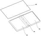
为了方便理解本申请实施例提供的转轴机构,下面首先说明一下其应用场景,该转轴机构可应用于移动终端,尤其为屏幕可折叠的移动终端,如手机、PDA(PersonalDigital Assistant,掌上电脑)、笔记本电脑或平板电脑等。本申请实施例所应用的移动终端均包含如图1中所示的结构:左壳体20、转轴机构10、右壳体30以及与两个壳体固定连接的柔性屏40。移动终端在使用时,可根据不同的使用情景进行折叠及展开。图1展示了移动终端展开(左壳体与右壳体的夹角为180°)时的状态,图2展示了移动终端折叠(左壳体与右壳体的夹角为0°)时的状态,移动终端展开和折叠过程即为左壳体20以及右壳体30绕转轴机构10转动的过程。为方便理解本申请实施例提供的转轴机构10,下面结合附图对其结构进行详细的说明。In order to facilitate the understanding of the rotating shaft mechanism provided by the embodiments of the present application, the application scenario of the rotating shaft mechanism is first described below. The rotating shaft mechanism can be applied to a mobile terminal, especially a mobile terminal with a foldable screen, such as a mobile phone, a PDA (Personal Digital Assistant, palmtop computer), laptop or tablet etc. The mobile terminals applied in the embodiments of the present application all include the structures shown in FIG. 1 : a
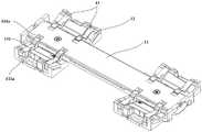
首先参照图3和图4,本申请实施例提供的转轴机构10主要包括主轴11,成对设置于主轴11的阻尼组,每对阻尼组沿垂直于主轴11的轴线方向分设于主轴11的两侧,每个阻尼组包括三个部分,分别为:转动组件12、位移组件13以及弹性模块14。其中,主轴11为一个支撑件,其同时起到转轴的作用;转动组件12与移动终端的壳体连接,其可作为该转轴机构10的主动转动部分来带动位移组件13转动,同时位移组件13与弹性模块14相配合可实现对转动组件12的转动位的限定。下面结合附图对该转轴机构10的各组成部分进行详细说明。Referring first to FIG. 3 and FIG. 4 , the
在具体设置主轴11时,该主轴11可以采用不同的结构。参照图4,本申请实施例提供的主轴11的整体结构为一个半圆柱形,为方便描述,将主轴11的半圆形的柱面称为主外轴111,将其平面称为主内轴112。且主内轴112与主外轴111之间固定连接,继续参考图4,该主内轴112与主外轴111之间可以通过螺钉15可拆卸的固定连接。当然除了图4所示的连接方式外,还可以采用卡扣或者铆钉将主内轴112与主外轴111固定连接。应当理解的是,上述主轴11采用的分体结构仅仅为一个具体的示例,本申请实施例提供的主轴11还可以采用其它的结构形式。此外,在主轴11支撑转动组件12时,该主轴11上设置了与转动组件12对应的结构。为方便理解该主轴11的内部结构,下面结合转动组件12一起说明一下主轴11的结构。When the
参照图3和图6,在具体设置转动组件12时,转动组件12设置有连接部121和支撑部122,连接部121可与主轴11的端部转动连接,支撑部122包括用于容置位移组件13的第一容置槽122a,以及用于容置弹性模块14的第二容置槽122b,第一容置槽122a的延伸方向与第二容置槽122b的延伸方向可以垂直,而第一容置槽122a的延伸方向与主轴11的轴线也可以垂直。3 and 6 , when the rotating
其中,转动组件12的连接部121的设置方式可以有多种。参照图5所示,主外轴111的端部设置有连接轴111c,该连接轴111c的轴线与主轴11的轴线平行;同时,参照图6,转动组件12的连接部121具有与连接轴111c相匹配的连接孔121a,从而可通过使连接轴111c穿设于连接孔121a的方式实现转动组件12与主轴11的连接。应当理解的是,该连接部121的设置只是一种示例,还可以采用铰接等方式来实现转动组件12与主轴11的连接。Wherein, the
参照图3、图6和图7,当转动组件12用于支撑位移组件13时,位移组件13的一端与主轴11转动连接,位移组件13的主体容置于第一容置槽122a,且其靠近第二容置槽122b一侧的侧壁设置有多个限位凹槽131。3, 6 and 7, when the rotating
为了实现位移组件13与主轴11的转动连接,参照图4,可以采用在主外轴111上设置第三容置槽111a的方案。具体的,主外轴111上设置有第三容置槽111a,主内轴112设置有用于露出第三容置槽111a的开口112a;结合图3,位移组件13靠近主轴11的一端容置于第三容置槽111a,且与第三容置槽111a转动连接。结合图7,位移组件13靠近主轴11的一端设置有支撑轴132,同时参照图5,第三容置槽111a包括可容置该支撑轴132的圆弧面111b。采用该结构时,需要先将位移组件13的支撑轴132放置于第三容置槽111a的圆弧面111b上,然后将主内轴112盖设于主外轴111上并加以紧固,从而可使支撑轴132卡设于第三容置槽111a,并可沿圆弧面111b转动。除此之外,位移组件13还可通过铰接或者枢装等方式来实现与第三容置槽111a的转动连接,并且,参照图3和图4,位移组件13在转动的过程中,主内轴112的开口112a不会对其造成干涉。In order to realize the rotational connection between the
参照图6和图7,在具体设置第一容置槽122a和位移组件13时,第一容置槽122a还开设有条形孔122c,该条形孔122c的延伸方向与第一容置槽122a的延伸方向相同,其中,条形孔122c的设置位置可以有多种,在图6所示的实施方式中,条形孔122c设置在第一容置槽122a远离所述第二容置槽122b的槽壁上。同时,参照图7,位移组件13还可以包括可沿条形孔122c滑动的滑动部133,其中,滑动部133可以但不限于为设置于位移组件13的圆柱形凸起。在位移组件13随转动组件12转动的过程中,滑动部133限位于条形孔122c,且可沿条形孔122c滑动,这样在转动组件12转动的过程中,可避免位移组件13脱离转动组件12,从而有效的提高位移组件13运动的可靠性。当然为了实现上述目的,还可以采用在第一容置槽122a中设置挡片等方式。6 and 7 , when the first
弹性模块14是实现转轴机构10旋转位维持的不可或缺的部分,在具体设置弹性模块14时,参照图4、图8和图10,弹性模块14可容置于第二容置槽122b,包括相抵接的滚珠141和弹性结构件142,滚珠141可沿位移组件13靠近第二容置槽122b的侧壁转动。The
为了对包含有该转动组件12的可折叠移动终端的折叠状态改变以及维持做更好的说明,可以同时参照图8、图9和图10,在图8、图9和图10中,移动终端的两个壳体之间的夹角为180°,参照图9,此时,滚珠141落在限位凹槽131中。当需要将移动终端的两个壳体之间的夹角从180°变为0°时,转动组件12绕主轴11转动,位移组件13随之转动,同时滚珠141沿位移组件13的侧壁滚动。参照图11和图12,当滚珠141落入限位凹槽131中时,限位凹槽131的槽壁阻止滚珠141继续在位移组件13上运动,从而使转动组件12停止转动,进而使移动终端的两个壳体维持于0°夹角的状态。由于位移组件13靠近第二容置槽122b的侧壁具有多个限位凹槽131,这样可通过使滚珠141落入对应的限位凹槽131中来实现转动组件12对应转动位的维持,例如,可通过合理设置使移动终端的两个壳体之间的夹角维持在90°。并且,在本申请实施方式中,参照图13和图14,当滚珠141在相邻两个限位凹槽131之间运动时,会使其与位移组件12之间产生恒定的摩擦力,从而可实现转动组件12与位移组件13之间具有恒定的阻尼,此时可使手感恒定。另外,值得一提的是,参照图9和图11,当位移组件13只在与移动终端的两个壳体之间的夹角为0°和180°相对应的位置设置有限位凹槽131时,结合图11和图13,用户在折叠该移动终端时,只需手动使两个壳体之间具有较小的夹角(例如30°),就可以使滚珠141在弹性结构件的作用下进入0°对应的限位凹槽131,以实现两个壳体的自合;同样的,用户在展开该移动终端时,只需手动使两个壳体之间具有较大的夹角(例如150°),就可以使滚珠141在弹性结构件的作用下进入180°对应的限位凹槽131,以实现两个壳体的自开。由此可见,采用本技术方案的转轴机构,可以实现可折叠移动终端的自开合,从而有利于提升用户体验。In order to better describe the change and maintenance of the folded state of the foldable mobile terminal including the rotating
在具体设置弹性结构件142时,参照图10、图12和图14时,在图10、图12和图14所示的实施例中,每个阻尼组中的转动组件12、位移组件13以及弹性模块14为一一对应的设置关系。以图12为例,转动组件12还包括设置于第二容置槽122b远离位移组件13一端的挡板123,弹性结构件142的一端固定于该挡板123。其中,弹性结构件142可以但不限于为弹簧,当弹性结构件142为弹簧时,为了实现对弹簧的限位,以使其在运动过程中不发生弯折,可以在挡板123上设置限位支柱124,从而使弹簧套设于限位支柱124,其中,弹簧可以为一条,也可以为多条,这样可以通过改变弹簧的数量来改变位移组件13与转动组件12之间的阻尼力的大小,除此之外,还可以通过改变弹簧的刚性来改变阻尼力的大小。同时,在该弹簧靠近位移组件13的一端还设置有连接板142a,连接板142a卡接于第二容置槽122b的槽壁,以使弹簧能够限位于第二容置槽122b。继续参照图10、图12和图14,连接板142a上也可以设置限位支柱124,并使弹簧套设于该限位支柱124。此时,滚珠141与连接板142a相抵接,并可沿连接板142a的表面运动,这样可减小弹性结构件142与滚珠141之间的摩擦,使滚珠141的运动更加灵活。10, 12 and 14, in the embodiment shown in FIGS. 10, 12 and 14, the
为了改变位移组件13与转动组件12之间的阻尼力的大小还可以通过改变滚珠141的数量来实现,具体的,参照图15和图16,在图15和图16所示的实施例中,每个阻尼组中的转动组件12为一个、位移组件13为两个,同时两个位移组件13共用一个弹性模块(图中未示出),但是转动组件12、弹性模块以及转轴11的设置方式稍有不同。其中,转动组件12设置有两个用于容置位移组件13的第一容置槽122a,主轴11上的第三容置槽111a与第一容置槽122a一一对应设置,以使位移组件13能够一一对应的容置于第一容置槽122a以及第三容置槽111a。此时,在具体设置弹性结构件142时,可参照图7,不同的是使弹性结构件142的两端各设置一个滚珠141,并使滚珠141能够沿对应的位移组件13的侧壁滚动。可以理解的是,在该实施方式中,两个位移组件13相对设置的侧壁上均设置有多个一一对应的限位凹槽131。弹性结构件142的具体设置方式可参照上一实施例,由弹簧或弹簧组,以及设置于弹簧(或弹簧组)端部的连接板142a组成,滚珠141与对应侧的连接板142a相抵接。其中,为避免弹簧(或弹簧组)在运动的过程中发生弯折,可在连接板142a上设置限位支柱,并使弹簧套设于对应的限位支柱即可。In order to change the magnitude of the damping force between the
第二方面,提供了一种可折叠移动终端,参照图1和图2,该移动终端包括上述任一项所述的转轴机构10,两个壳体,分别为左壳体20和右壳体30,以及分别与左壳体20和右壳体30固定连接的柔性屏40。其中,结合图3,所述两个壳体分设于转轴机构10的两侧,且每个壳体与位于同一侧的转动组件12固定连接。该移动终端在使用时,壳体带动转动组件12绕主轴11转动,以使转动组件12与位移组件13之间发生相对运动,同时,参照图10,弹性结构件142使滚珠141在位移组件13的侧壁上运动产生摩擦力,以形成阻尼。当滚珠141运动并落入位移组件13的对应的限位凹槽131(图10中未示出,可参照图7、图9和图11)中时,滚珠141停止滚动,从而使转动组件12停止转动,壳体的转动位被限制,进而实现对移动终端的对应折叠状态的维持。此时,可继续用力使滚珠141从限位凹槽131中出来继续沿位移组件13的侧壁运动,直到滚珠141进入下一个限位凹槽131。In a second aspect, a foldable mobile terminal is provided. Referring to FIG. 1 and FIG. 2 , the mobile terminal includes the
以上,仅为本申请的具体实施方式,但本申请的保护范围并不局限于此,任何熟悉本技术领域的技术人员在本申请揭露的技术范围内,可轻易想到变化或替换,都应涵盖在本申请的保护范围之内。因此,本申请的保护范围应以权利要求的保护范围为准。The above are only specific embodiments of the present application, but the protection scope of the present application is not limited to this. Any person skilled in the art can easily think of changes or replacements within the technical scope disclosed in the present application, and should cover within the scope of protection of this application. Therefore, the protection scope of the present application shall be subject to the protection scope of the claims.
Claims (10)
Priority Applications (1)
| Application Number | Priority Date | Filing Date | Title |
|---|---|---|---|
| CN201910569633.7ACN112153832B (en) | 2019-06-27 | 2019-06-27 | A rotating shaft mechanism and a foldable mobile terminal |
Applications Claiming Priority (1)
| Application Number | Priority Date | Filing Date | Title |
|---|---|---|---|
| CN201910569633.7ACN112153832B (en) | 2019-06-27 | 2019-06-27 | A rotating shaft mechanism and a foldable mobile terminal |
Publications (2)
| Publication Number | Publication Date |
|---|---|
| CN112153832A CN112153832A (en) | 2020-12-29 |
| CN112153832Btrue CN112153832B (en) | 2022-04-22 |
Family
ID=73868906
Family Applications (1)
| Application Number | Title | Priority Date | Filing Date |
|---|---|---|---|
| CN201910569633.7AActiveCN112153832B (en) | 2019-06-27 | 2019-06-27 | A rotating shaft mechanism and a foldable mobile terminal |
Country Status (1)
| Country | Link |
|---|---|
| CN (1) | CN112153832B (en) |
Families Citing this family (2)
| Publication number | Priority date | Publication date | Assignee | Title |
|---|---|---|---|---|
| CN112887460B (en)* | 2021-01-22 | 2023-05-23 | 维沃移动通信有限公司 | Folding mechanism and electronic equipment |
| CN115250299B (en)* | 2021-04-25 | 2025-07-11 | 华为技术有限公司 | Folding mechanism and electronic equipment |
Citations (5)
| Publication number | Priority date | Publication date | Assignee | Title |
|---|---|---|---|---|
| CN207297616U (en)* | 2017-08-22 | 2018-05-01 | 仁宝电脑工业股份有限公司 | Folding electronic device |
| WO2018210182A1 (en)* | 2017-05-17 | 2018-11-22 | Oppo广东移动通信有限公司 | Foldable mobile terminal |
| WO2018210196A1 (en)* | 2017-05-17 | 2018-11-22 | Oppo广东移动通信有限公司 | Foldable mobile terminal |
| CN208656822U (en)* | 2018-07-13 | 2019-03-26 | Oppo广东移动通信有限公司 | Folding devices and electronic equipment |
| CN109681521A (en)* | 2018-12-29 | 2019-04-26 | 兆利科技工业股份有限公司 | A kind of rotary axis module of folding type device |
Family Cites Families (6)
| Publication number | Priority date | Publication date | Assignee | Title |
|---|---|---|---|---|
| CN2672692Y (en)* | 2003-09-30 | 2005-01-19 | 联想(北京)有限公司 | Damper of cell phone camera head rotary shaft |
| CN203402772U (en)* | 2013-07-30 | 2014-01-22 | 深圳市一康智科技有限公司 | Durable wire taking-up device |
| CN104676522B (en)* | 2013-11-29 | 2019-06-07 | 深圳市海洋王照明工程有限公司 | Lamps and lanterns |
| CN107135288B (en)* | 2017-04-25 | 2020-03-24 | 珠海市魅族科技有限公司 | Folding terminal with flexible screen |
| CN207910845U (en)* | 2018-03-28 | 2018-09-25 | 京东方科技集团股份有限公司 | A kind of Foldable mobile terminal |
| CN208638396U (en)* | 2018-07-27 | 2019-03-22 | Oppo广东移动通信有限公司 | Foldable mobile terminal |
- 2019
- 2019-06-27CNCN201910569633.7Apatent/CN112153832B/enactiveActive
Patent Citations (5)
| Publication number | Priority date | Publication date | Assignee | Title |
|---|---|---|---|---|
| WO2018210182A1 (en)* | 2017-05-17 | 2018-11-22 | Oppo广东移动通信有限公司 | Foldable mobile terminal |
| WO2018210196A1 (en)* | 2017-05-17 | 2018-11-22 | Oppo广东移动通信有限公司 | Foldable mobile terminal |
| CN207297616U (en)* | 2017-08-22 | 2018-05-01 | 仁宝电脑工业股份有限公司 | Folding electronic device |
| CN208656822U (en)* | 2018-07-13 | 2019-03-26 | Oppo广东移动通信有限公司 | Folding devices and electronic equipment |
| CN109681521A (en)* | 2018-12-29 | 2019-04-26 | 兆利科技工业股份有限公司 | A kind of rotary axis module of folding type device |
Also Published As
| Publication number | Publication date |
|---|---|
| CN112153832A (en) | 2020-12-29 |
Similar Documents
| Publication | Publication Date | Title |
|---|---|---|
| US12081686B2 (en) | Hinge mechanism and foldable mobile terminal | |
| CN107135288B (en) | Folding terminal with flexible screen | |
| CN110159648B (en) | Rotating shaft module and folding electronic device | |
| TWI462682B (en) | Connecting mechanism and related electronic device | |
| CN110515426B (en) | Rotating shaft mechanism and electronic equipment | |
| CN112153188A (en) | Folding terminal | |
| CN112153832B (en) | A rotating shaft mechanism and a foldable mobile terminal | |
| CN113643609A (en) | Display device | |
| CN114449067B (en) | Folding device and foldable electronic device | |
| CN119072041A (en) | Hinge and folding display device | |
| CN115949665A (en) | Hinge mechanism and foldable electronic equipment | |
| US20240288903A1 (en) | Hinge and display device | |
| WO2025113359A1 (en) | Hinge mechanism and electronic device | |
| CN117419097B (en) | Rotating shaft mechanism and foldable equipment | |
| CN113643610A (en) | display device | |
| KR101113712B1 (en) | Free Stop Hinge Modules for Mobile Devices | |
| CN115250299B (en) | Folding mechanism and electronic equipment | |
| CN114650326B (en) | Hinge mechanism and foldable electronic device | |
| CN115789072A (en) | Hinge assembly and electronic device | |
| CN212850577U (en) | Folding components and terminal equipment | |
| TWI817506B (en) | Portable electric device | |
| CN115623711B (en) | Hinge assembly and folding screen terminal | |
| TW201410122A (en) | Rotating mechanism and electronic device | |
| CN119496842A (en) | Foldable mechanism and foldable terminal | |
| CN109114096B (en) | Rotating shaft structure |
Legal Events
| Date | Code | Title | Description |
|---|---|---|---|
| PB01 | Publication | ||
| PB01 | Publication | ||
| SE01 | Entry into force of request for substantive examination | ||
| SE01 | Entry into force of request for substantive examination | ||
| GR01 | Patent grant | ||
| GR01 | Patent grant |