CN112140582A - Composite material transverse stabilizer bar preparation method and transverse stabilizer bar prepared by same - Google Patents
Composite material transverse stabilizer bar preparation method and transverse stabilizer bar prepared by sameDownload PDFInfo
- Publication number
- CN112140582A CN112140582ACN202010743254.8ACN202010743254ACN112140582ACN 112140582 ACN112140582 ACN 112140582ACN 202010743254 ACN202010743254 ACN 202010743254ACN 112140582 ACN112140582 ACN 112140582A
- Authority
- CN
- China
- Prior art keywords
- stabilizer bar
- layer
- transverse stabilizer
- wrapping
- transverse
- Prior art date
- Legal status (The legal status is an assumption and is not a legal conclusion. Google has not performed a legal analysis and makes no representation as to the accuracy of the status listed.)
- Pending
Links
Images


Classifications
- B—PERFORMING OPERATIONS; TRANSPORTING
- B29—WORKING OF PLASTICS; WORKING OF SUBSTANCES IN A PLASTIC STATE IN GENERAL
- B29C—SHAPING OR JOINING OF PLASTICS; SHAPING OF MATERIAL IN A PLASTIC STATE, NOT OTHERWISE PROVIDED FOR; AFTER-TREATMENT OF THE SHAPED PRODUCTS, e.g. REPAIRING
- B29C70/00—Shaping composites, i.e. plastics material comprising reinforcements, fillers or preformed parts, e.g. inserts
- B29C70/04—Shaping composites, i.e. plastics material comprising reinforcements, fillers or preformed parts, e.g. inserts comprising reinforcements only, e.g. self-reinforcing plastics
- B29C70/28—Shaping operations therefor
- B29C70/30—Shaping by lay-up, i.e. applying fibres, tape or broadsheet on a mould, former or core; Shaping by spray-up, i.e. spraying of fibres on a mould, former or core
- B29C70/34—Shaping by lay-up, i.e. applying fibres, tape or broadsheet on a mould, former or core; Shaping by spray-up, i.e. spraying of fibres on a mould, former or core and shaping or impregnating by compression, i.e. combined with compressing after the lay-up operation
- B29C70/345—Shaping by lay-up, i.e. applying fibres, tape or broadsheet on a mould, former or core; Shaping by spray-up, i.e. spraying of fibres on a mould, former or core and shaping or impregnating by compression, i.e. combined with compressing after the lay-up operation using matched moulds
- B—PERFORMING OPERATIONS; TRANSPORTING
- B29—WORKING OF PLASTICS; WORKING OF SUBSTANCES IN A PLASTIC STATE IN GENERAL
- B29C—SHAPING OR JOINING OF PLASTICS; SHAPING OF MATERIAL IN A PLASTIC STATE, NOT OTHERWISE PROVIDED FOR; AFTER-TREATMENT OF THE SHAPED PRODUCTS, e.g. REPAIRING
- B29C70/00—Shaping composites, i.e. plastics material comprising reinforcements, fillers or preformed parts, e.g. inserts
- B29C70/04—Shaping composites, i.e. plastics material comprising reinforcements, fillers or preformed parts, e.g. inserts comprising reinforcements only, e.g. self-reinforcing plastics
- B29C70/28—Shaping operations therefor
- B29C70/54—Component parts, details or accessories; Auxiliary operations, e.g. feeding or storage of prepregs or SMC after impregnation or during ageing
- B29C70/545—Perforating, cutting or machining during or after moulding
- B—PERFORMING OPERATIONS; TRANSPORTING
- B29—WORKING OF PLASTICS; WORKING OF SUBSTANCES IN A PLASTIC STATE IN GENERAL
- B29L—INDEXING SCHEME ASSOCIATED WITH SUBCLASS B29C, RELATING TO PARTICULAR ARTICLES
- B29L2031/00—Other particular articles
- B29L2031/30—Vehicles, e.g. ships or aircraft, or body parts thereof
Landscapes
- Chemical & Material Sciences (AREA)
- Engineering & Computer Science (AREA)
- Composite Materials (AREA)
- Mechanical Engineering (AREA)
- Woven Fabrics (AREA)
Abstract
Description
Translated fromChinese技术领域technical field
本发明属于汽车横向稳定杆领域,具体涉及一种应用于汽车悬架的复合材料横向稳定杆的制备方法及其制得的横向稳定杆。The invention belongs to the field of automobile lateral stabilizer bars, and in particular relates to a preparation method of a composite material lateral stabilizer bar applied to an automobile suspension and the prepared lateral stabilizer bar.
背景技术Background technique
随着汽车排放标准的不断升级及能源短缺、环境污染问题的日益严峻,汽车轻量化成为现代汽车的主要发展趋势。横向稳定杆是汽车悬架系统的关键零部件之一,其功用是提供汽车的侧倾角刚度,防止车身在转弯时发生过大的横向侧倾,进而使车身保持平衡,并改善汽车的平顺性。若在汽车转弯过程中横向稳定杆发生断裂,则会使车身失稳进而诱发侧翻等安全事故。因此,横向稳定杆实际上是一个横置的在汽车转弯过程中承受部分垂向及侧向载荷的弹性元件,对行车安全及整车操纵稳定性及舒适性都有非常关键的影响。目前汽车采用的横向稳定杆均用弹簧钢制成,总体形状呈"U"形,横置安装在汽车的前悬架、后悬架上或两者兼有,其自重根据车型不同可达2kg至10kg,具有可观的轻量化潜力,从而提高操作的安全和舒适性。With the continuous escalation of vehicle emission standards, energy shortages, and increasingly severe environmental pollution problems, vehicle lightweighting has become the main development trend of modern vehicles. The stabilizer bar is one of the key components of the car suspension system. Its function is to provide the roll angle stiffness of the car, prevent the body from excessive lateral roll during cornering, so as to maintain the balance of the car body and improve the ride comfort of the car . If the stabilizer bar breaks during the turning process of the car, it will cause the vehicle body to become unstable and induce safety accidents such as rollover. Therefore, the stabilizer bar is actually a transverse elastic element that bears part of the vertical and lateral loads during the turning process of the car, which has a very critical impact on the driving safety, the handling stability and comfort of the whole vehicle. At present, the stabilizer bars used in automobiles are all made of spring steel, and the overall shape is "U" shape. They are installed horizontally on the front suspension, rear suspension or both of the automobile. Its dead weight can reach 2kg according to different models. up to 10kg, with considerable light-weighting potential, thus increasing the safety and comfort of operation.
鉴于上述问题,本发明在现有金属横向稳定杆基础上,提出一种应用于汽车悬架的复合材料横向稳定杆结构及其制备方法。该复合材料横向稳定杆不但具有质量轻、结构件一体成型、无锈蚀问题等优点,而且能提升整车平顺性,本案由此产生。In view of the above problems, the present invention proposes a composite material stabilizer bar structure and a preparation method for the vehicle suspension on the basis of the existing metal stabilizer bar. The composite material lateral stabilizer bar not only has the advantages of light weight, integral molding of structural parts, no corrosion problems, etc., but also can improve the ride comfort of the whole vehicle.
发明内容SUMMARY OF THE INVENTION
本发明提供一种复合材料横向稳定杆制备方法及其制得的横向稳定杆,该制备方法速度快,效率高,且其制成的横向稳定杆具有轻量化,高强度,不易生锈的特点;具体地,本发明是通过以下技术方案实现:The invention provides a preparation method of a composite material transverse stabilizer bar and the obtained transverse stabilizer bar. The preparation method has high speed and high efficiency, and the manufactured transverse stabilizer bar has the characteristics of light weight, high strength and not easy to rust. Specifically, the present invention is realized through the following technical solutions:
一种复合材料横向稳定杆的制备方法,其制备方法步骤如下所述,A preparation method of a composite lateral stabilizer bar, the preparation method steps are as follows:
步骤一、根据设计的横向稳定杆尺寸形状,制备横向稳定杆预成型体:根据设计需要,制备横向稳定杆的中心层、包裹层,并拼接中心层材料棒、包裹层,形成横向稳定杆预成型体;
步骤二、固化横向稳定杆成型:横向稳定杆预成型体置入模具,向模具内注入树脂固化;
步骤三、横向稳定杆后固化及后处理。Step 3: Post-curing and post-processing of the stabilizer bar.
进一步,步骤一中,裁切不同编织方式的增强纤维预浸料,并将其依次由内而外的包裹在预先准备的制作中心层的材料棒上,形成初步的包裹层,从而形成横向稳定杆预成型体,并用绑带扎节以防止预成型体散开。Further, in
进一步,步骤一中,横向稳定杆为实心结构时,则用聚氨酯或橡胶材料作为中心层填充;横向稳定杆为空心结构时,则用可溶性材料作为中心层填充,稳定杆成型后将其溶解。Further, in
进一步,步骤三中,将成型的横向稳定杆脱模并进一步固化,完成后进行抛光打磨;若制作空心稳定杆则需去除中心层中填充的材料。Further, in
进一步,步骤一中,增加制备并拼接横向稳定杆末端的花键结构步骤;增加步骤四,根据设计需要,制备并装配转接接头于稳定杆末端。Further, in the first step, the steps of preparing and splicing the spline structure at the end of the lateral stabilizer bar are added; and the fourth step is added, according to the design requirements, preparing and assembling the adapter joint on the end of the stabilizer bar.
进一步,步骤一中,横向稳定杆末端的花键结构其制作工艺为,裁切用于制作花键凸起的强芯毡,将强芯毡插入横向稳定杆预成型体末端内部,在拟形成花键区域边界处用高强度绑带扎节,该绑带随横向稳定杆预成型体一起固化在杆身中;步骤四中,制备金属转接接头,将金属转接接头花键配合面上涂抹高强度粘接剂,并将金属转接接头花键配合面与复合材料杆身的花键表面配合装配,实现包括粘接及机械连接的混合连接。Further, in
进一步,步骤二中,固化用的树脂采用增强增韧环氧树脂或聚氨酯树脂或其他适应模压、拉挤或RTM工艺的树脂体系。Further, in
一种根据上述复合材料横向稳定杆制备方法制得的横向稳定杆,制得的横向稳定杆的杆身包括中心层和包裹在中心层外的一层或多层包裹层;包裹层为增强纤维编织而成的复合材料;杆身为实体或者内部空心结构。A stabilizer bar prepared according to the above-mentioned composite material stabilizer bar preparation method, the body of the prepared stabilizer bar comprises a center layer and one or more layers of wrapping layers wrapped around the center layer; the wrapping layer is a reinforcing fiber Woven composite material; the shaft is solid or internally hollow.
进一步,当中心层外包裹一层包裹层,则该包裹层中的增强纤维编织方式为平纹编织;当中心层外包裹两层包裹层,则最外层的包裹层中的增强纤维编织方式为平纹编织,其内侧的中间包裹层中的增强纤维编织方式为单向编织。Further, when the center layer is wrapped with a wrapping layer, the reinforcing fiber weaving method in the wrapping layer is plain weave; when the center layer is wrapped with two wrapping layers, the reinforcing fiber weaving method in the outermost wrapping layer is In plain weave, the reinforcing fibers in the middle wrapping layer on the inner side are woven in one direction.
进一步,增强纤维排布方向与杆身轴线呈锐角,该锐角在30°至60°之间。Further, the arrangement direction of the reinforcing fibers forms an acute angle with the shaft axis, and the acute angle is between 30° and 60°.
本发明的有益效果在于:The beneficial effects of the present invention are:
复合材料横向稳定杆是采用纤维增强树脂基复合材料制作的横向稳定杆,其内部引入了编织纤维增强体。在相同刚度的前提下,复合材料横向稳定杆的重量可比金属横向稳定杆轻40%以上。此外,由于复合材料具有比强度、比模量高,不生锈、具有一定的阻尼等优越特性,因此复合材料横向稳定杆的储能能力及衰减振动的能力也比金属横向稳定杆好。因此,复合材料横向稳定杆的综合性能明显优于金属横向稳定杆,具有良好的应用前景。同时,横向稳定杆主要结构一体成型,结构整体可靠性高,能提升整车平顺性。The composite stabilizer bar is a stabilizer bar made of fiber-reinforced resin-based composite materials, and a braided fiber reinforcement is introduced into it. On the premise of the same stiffness, the weight of the composite stabilizer bar can be more than 40% lighter than that of the metal stabilizer bar. In addition, due to the superior characteristics of composite materials such as high specific strength and specific modulus, no rust, and certain damping, the energy storage capacity and vibration damping ability of composite stabilizer bars are also better than those of metal stabilizers. Therefore, the comprehensive performance of the composite stabilizer bar is obviously better than that of the metal stabilizer bar, and it has a good application prospect. At the same time, the main structure of the stabilizer bar is integrally formed, and the overall reliability of the structure is high, which can improve the ride comfort of the whole vehicle.
附图说明Description of drawings
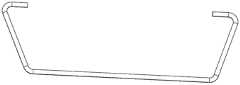
图1为本发明提供的一种无转换接头的复合材料横向稳定杆结构示意图;1 is a schematic structural diagram of a composite material stabilizer bar without a transition joint provided by the present invention;
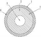
图2为本发明提供的一种两层包裹层的实心杆身横截面图;2 is a cross-sectional view of a solid shaft of a two-layer wrapping layer provided by the present invention;
图3为本发明提供的一种一层包裹层的实心杆身横截面图;3 is a cross-sectional view of a solid shaft of a one-layer wrapping layer provided by the present invention;
图4为本发明提供的一种两层包裹层的空心杆身横截面图;4 is a cross-sectional view of a hollow shaft of a two-layer wrapping layer provided by the present invention;
图5为本发明提供的一种一层包裹层的空心杆身横截面图;5 is a cross-sectional view of a hollow shaft of a one-layer wrapping layer provided by the present invention;
图6为本发明提供的一种连接在横向稳定杆两端的转换接头结构图;6 is a structural diagram of a transition joint connected to both ends of the stabilizer bar provided by the present invention;
图7为本发明提供的一种转接头结构图;FIG. 7 is a structural diagram of an adapter provided by the present invention;
图8为本发明提供的一种复合材料稳定杆杆身末端花键内部结构示意图。FIG. 8 is a schematic diagram of the internal structure of a spline at the end of a composite stabilizer bar shaft provided by the present invention.
其中:1.最外包裹层;2.中间包裹层;3.中心层;4.杆身;5.转换接头;6.平纹布;7.单向布。Among them: 1. Outer wrapping layer; 2. Middle wrapping layer; 3. Center layer; 4. Shaft; 5. Conversion joint; 6. Plain weave; 7. Unidirectional cloth.
具体实施方式Detailed ways
下面结合附图和具体实施方式对本发明作进一步说明。The present invention will be further described below with reference to the accompanying drawings and specific embodiments.
如图1、图2、图3、图4、图5所示,一种复合材料横向稳定杆,形状呈U形,其杆身4的横截面为圆形;横向稳定杆的杆身4包括中心层3和包裹在中心层3外的一层或多层包裹层;所述包裹层由增强纤维编织而成的复合材料组成。As shown in Figure 1, Figure 2, Figure 3, Figure 4, Figure 5, a composite material stabilizer bar has a U-shaped shape, and the cross section of its shaft 4 is circular; the shaft 4 of the stabilizer bar includes The
由于横向稳定杆的最外表面的受力条件最为恶劣,因此最外包裹层1中的复合材料内增强纤维编织方式采取平纹编织方式,即经向和纬向的增强纤维交叉编织形成平纹布6;这种平纹布6不但可以保证杆身4的强度,而且能使杆身4通过整体编织的增强纤维包覆起来,进而增强杆身4的疲劳寿命及抗冲击性能。Since the stress condition on the outermost surface of the lateral stabilizer bar is the worst, the weaving method of the inner reinforcing fibers of the composite material in the
如图2、图4所示,为了使横向稳定杆具有最佳的抗扭转性能及疲劳可靠性,因此在最外包裹层1的内侧添加一层中间包裹层2,形成两层包裹层,包裹在中心层3外,其中,中间包裹层2中的复合材料内增强纤维编织方式为单向编织,即增强纤维单向排列形成单向布7。As shown in Figure 2 and Figure 4, in order to make the stabilizer bar have the best torsion resistance and fatigue reliability, an
根据材料力学,扭转变形条件下,当增强纤维排布方向与杆身4轴线呈一锐角时,该锐角范围在30°至60°之间,尤其是当锐角角度为45°时,能充分发挥增强纤维高强度、高模量特性,因此平纹布6的经向和纬向增强纤维与杆身4轴线呈45°,单向布7的增强纤维排布方向与杆身4轴线呈45°。According to material mechanics, under the condition of torsional deformation, when the arrangement direction of the reinforcing fibers forms an acute angle with the axis of the shaft 4, the acute angle ranges from 30° to 60°, especially when the acute angle is 45°, it can give full play to the The reinforcing fibers have high strength and high modulus, so the warp and weft reinforcing fibers of the
根据使用环境所要求横向稳定杆的强度及疲劳寿命,选择横向稳定杆中处于中心位置的中心层3是否填充。According to the strength and fatigue life of the stabilizer bar required by the use environment, choose whether to fill the
当横向稳定杆用于大型SUV车型等载荷较大的车型中时,为了提高横向稳定杆的抗扭转能力和疲劳寿命,则其处于中心位置的中心层3需要填充,此时该横向稳定杆为实心结构;该中心层3选择为具有一定弹性的聚氨酯或橡胶材料,利用聚氨酯或橡胶材料的弹性变形,协调复合材料杆身4的内部变形,从而提高复合材料杆身4的抗扭转能力及疲劳寿命。When the stabilizer bar is used in a vehicle with a large load such as a large SUV, in order to improve the torsion resistance and fatigue life of the stabilizer bar, the
如图4、图5所示,当横向稳定杆用于载荷较小的小型车型时,在满足轻度和使用寿命的腔体下,为了提高总成的轻量化性能,则其处于中心位置的中心层3无需填充,此时该横向稳定杆为空心结构。As shown in Figure 4 and Figure 5, when the stabilizer bar is used for small vehicles with a small load, in order to improve the lightweight performance of the assembly under the cavity that meets the lightness and service life, it is located in the center position. The
部分车型的金属横向稳定杆出于可靠性的考虑,杆身4末端未设置接头结构,直接利用一段弯折的杆身4通过橡胶衬套与车架连接点连接。在这种情况下,直接将全部杆身4用复合材料制作即可。然而,如图1所示,部分车型的金属横向稳定杆末端采用开孔结构,通过橡胶垫或球头销与悬架导向臂连接,此时拟替换的复合材料横向稳定杆杆身4末端不可避免地需要设计开孔接头结构,而开孔部位是复合材料稳定杆杆身4的薄弱区域,因此需针对此应用场景中的横向稳定杆两端接头结构进行重点设计。For the sake of reliability, the metal stabilizer bar of some models does not have a joint structure at the end of the rod body 4, and a section of the bent rod body 4 is directly connected to the frame connection point through a rubber bushing. In this case, all the shafts 4 may be directly made of the composite material. However, as shown in Figure 1, the metal stabilizer bar end of some models adopts an open-hole structure and is connected to the suspension guide arm through a rubber pad or ball stud. At this time, the end of the composite stabilizer bar shaft 4 to be replaced cannot be used. It is avoided to design the opening joint structure, and the opening part is the weak area of the composite stabilizer bar shaft 4, so it is necessary to focus on the design of the joint structure at both ends of the stabilizer bar in this application scenario.
如图6、图7、图8所示,针对此问题,发明的横向稳定杆两末端头连接有转换接头5,其中杆身4上设置有内花键,转换接头5上设置有外花键,内外花键配合,使得两者连接。其中,复合材料杆身4末端设花键处的铺层方案不变,并保持该区域与杆身4其他铺层增强纤维的连续性,以保证接头载荷的可靠传递。在此前提下,在杆身4末端的中心层3外引入强芯毡等强化物,以填充杆身4末端凸出的花键,强芯毡等强化物外被杆身4的包裹层铺层包覆,这样既可形成杆身4花键的几何结构,也可保证花键的载荷通过连续增强纤维传递,进而保证接头连接的可靠性。为保证结构的整体强度和可靠性,设计过程中还需对接头进行强度校核和可靠性分析。As shown in Figure 6, Figure 7, Figure 8, in response to this problem, the two ends of the stabilizer bar of the invention are connected with
所述复合材料横向稳定杆杆身4通过如下工艺制备:The composite stabilizer bar shaft 4 is prepared by the following process:
一、根据设计的横向稳定杆尺寸形状,制备横向稳定杆预成型体。1. According to the designed size and shape of the stabilizer bar, prepare the stabilizer bar preform.
①根据设计需要,制备横向稳定杆各组件。① Prepare each component of the stabilizer bar according to the design requirements.
根据设计需要,裁切用于制作包裹层的不同编织方式的增强纤维预浸料,增强纤维预浸料为增强纤维编织而成的复合材料的半制品;将增强纤维预浸料裁切为与复合材料横向稳定杆的铺层长度、宽度相适应的形状,即其宽度与复合材料横向稳定杆轴线长度相同,长度与复合材料横向稳定杆的铺层层数有关,而铺层层数由复合材料横向稳定杆的刚度决定。According to the design needs, cut the reinforcing fiber prepreg used to make the wrapping layer with different weaving methods, and the reinforcing fiber prepreg is a semi-product of the composite material woven by the reinforcing fiber; The shape of the layer length and width of the composite stabilizer bar, that is, its width is the same as the axis length of the composite stabilizer bar, and the length is related to the number of layers of the composite stabilizer bar, and the number of layers is determined by the composite stabilizer bar. Material The stiffness of the stabilizer bar determines.
根据设计需要,准备用于制作横向稳定杆中心层3材料棒:其中,横向稳定杆为实心结构,则用聚氨酯棒或橡胶棒作为其中心层3填充;横向稳定杆为空心结构,则用可溶性材料作为中心层3填充。According to the design needs, prepare the material rod for making the
如果稳定杆设计花键,则裁切用于制作花键的强芯毡,其规格根据花键空腔的填充需要确定。If the stabilizer bar is designed with splines, cut the strong core felt used to make the splines, and its specifications are determined according to the filling needs of the spline cavities.
注意如果横向稳定杆末端设计有转换接头5,则中心层3材料棒的总长度短于杆身4芯轴长度,从而为花键接头成型提供操作空间。Note that if the end of the stabilizer bar is designed with a transition joint 5, the overall length of the material rod of the
②根据设计需要,拼接横向稳定杆各组件。② According to the design requirements, splicing the components of the lateral stabilizer bar.
根据需要,拼接横向稳定杆杆身4:将裁切后的不同编织方式的增强纤维预浸料依次由内而外的卷曲包裹在预先准备的中心层3材料棒上,形成横向稳定杆预成型体,并用绑带扎节以防止预成型体散开。Splicing the stabilizer bar shaft 4 as needed: The reinforced fiber prepregs of different weaving methods after cutting are rolled and wrapped on the
③如果稳定杆设计花键,则拼接横向稳定杆末端的花键结构。将预先裁切好的强芯毡等强化物插入预成型体末端的铺层内部。由于预成型体末端的铺层为确定的,因此需引入尼龙制作的花键成型骨架将强芯毡及原有铺层撑起,以形成花键形状。为防止端部铺层撑起影响杆身4整体铺层状态,在拟形成花键区域边界处用高强度绑带扎节,该绑带随预成型体一起固化在复合材料杆身4中。③ If the stabilizer bar is designed with splines, splice the spline structure at the end of the stabilizer bar. Reinforcement such as pre-cut core felt is inserted inside the layup at the end of the preform. Since the layup at the end of the preform is definite, a spline forming skeleton made of nylon needs to be introduced to support the strong core felt and the original layup to form a spline shape. In order to prevent the end laminations from affecting the overall lamination state of the shaft 4, high-strength straps are used to bind the joints at the boundary of the spline area to be formed, and the straps are cured in the composite shaft 4 together with the preform.
二、固化横向稳定杆成型。2. Curing the stabilizer bar molding.
①横向稳定杆预成型体置入模具。①The stabilizer bar preform is placed in the mold.
将制得的预成型体按照预定位置放置在模具内模上,模腔形状与复合材料横向稳定杆杆身4形状相对应。The prepared preform is placed on the inner mold of the mold according to a predetermined position, and the shape of the mold cavity corresponds to the shape of the composite stabilizer bar shaft 4 .
②模具内注入树脂。②Inject resin into the mold.
将外模合模,向模具内进一步注射树脂,使树脂充分浸润预成型体,并根据所选树脂的固化曲线选取合适的温度及模具压力,使复合材料横向稳定杆固化成型。The outer mold is closed, and resin is further injected into the mold to fully infiltrate the preform, and the appropriate temperature and mold pressure are selected according to the curing curve of the selected resin to cure the composite stabilizer bar.
三、横向稳定杆后固化及后处理。3. Post-curing and post-processing of the stabilizer bar.
①脱模固化。①Release and curing.
在复合材料横向稳定杆完成固化成型并脱模后,将其放入恒温箱内,在120℃温度下后固化2小时。After the composite stabilizer bar is cured and molded and demolded, it is placed in a constant temperature oven and post-cured at a temperature of 120° C. for 2 hours.
②横向稳定杆打磨。②The stabilizer bar is polished.
在完成后固化处理后,对其进行去毛刺及打磨处理。After the post-curing treatment is completed, it is deburred and sanded.
对涉及可溶性结构的复合材料杆身4形式,杆身为空心结构时,进行化学试剂融溶处理,以将杆身4内部的可溶性结构溶解掉,制得最终复合材料横向稳定杆杆身4。For the form of the composite material shaft 4 involving a soluble structure, when the shaft is a hollow structure, a chemical reagent melting treatment is performed to dissolve the soluble structure inside the shaft 4, and the final composite material lateral stabilizer shaft 4 is obtained.
四、如果稳定杆连接有花键,则根据设计需要,制备并装配转接接头。4. If the stabilizer bar is connected with splines, prepare and assemble the adapter according to the design requirements.
①制备转换接头5。① Prepare the
通过压铸、机械加工、热处理等手段制备金属转接接头。The metal adapter is prepared by means of die casting, machining, heat treatment, etc.
②装配转换接头5。② Assemble the
将金属转接接头花键配合面上涂抹高强度粘接剂,并将金属转接接头花键配合面与复合材料杆身4的花键表面配合装配,实现包括粘接及机械连接的混合连接。Apply high-strength adhesive on the spline mating surface of the metal adapter, and assemble the spline mating surface of the metal adapter with the spline surface of the composite material shaft 4 to realize a hybrid connection including bonding and mechanical connection .
上述增强纤维根据成本及性能要求选用不同编织方式的单向布7预浸料或平纹布6增强纤维预浸料,固化用的树脂采用增强增韧环氧树脂或聚氨酯树脂或其他适应模压、拉挤或RTM工艺的树脂体系。The above-mentioned reinforcing fibers are unidirectional fabrics with different weaving methods according to cost and performance requirements. Resin systems for extrusion or RTM processes.
至此,复合材料横向稳定杆制备完成。So far, the preparation of the composite stabilizer bar is completed.
以上是本发明优选实施方式,在本发明构思前提下所做出若干其他简单替换和改动,都应当视为属于本发明的保护范畴。The above are the preferred embodiments of the present invention, and some other simple replacements and modifications made under the premise of the present invention should be regarded as belonging to the protection scope of the present invention.
Claims (10)
Priority Applications (1)
| Application Number | Priority Date | Filing Date | Title |
|---|---|---|---|
| CN202010743254.8ACN112140582A (en) | 2020-07-29 | 2020-07-29 | Composite material transverse stabilizer bar preparation method and transverse stabilizer bar prepared by same |
Applications Claiming Priority (1)
| Application Number | Priority Date | Filing Date | Title |
|---|---|---|---|
| CN202010743254.8ACN112140582A (en) | 2020-07-29 | 2020-07-29 | Composite material transverse stabilizer bar preparation method and transverse stabilizer bar prepared by same |
Publications (1)
| Publication Number | Publication Date |
|---|---|
| CN112140582Atrue CN112140582A (en) | 2020-12-29 |
Family
ID=73889019
Family Applications (1)
| Application Number | Title | Priority Date | Filing Date |
|---|---|---|---|
| CN202010743254.8APendingCN112140582A (en) | 2020-07-29 | 2020-07-29 | Composite material transverse stabilizer bar preparation method and transverse stabilizer bar prepared by same |
Country Status (1)
| Country | Link |
|---|---|
| CN (1) | CN112140582A (en) |
Cited By (2)
| Publication number | Priority date | Publication date | Assignee | Title |
|---|---|---|---|---|
| CN113943471A (en)* | 2021-11-04 | 2022-01-18 | 成都鲁晨新材料科技有限公司 | Low-density prepreg, preparation method and application |
| CN114911355A (en)* | 2021-02-09 | 2022-08-16 | 华为技术有限公司 | Electronic equipment, balancing pole and preparation method thereof |
Citations (3)
| Publication number | Priority date | Publication date | Assignee | Title |
|---|---|---|---|---|
| CN104085120A (en)* | 2014-06-30 | 2014-10-08 | 江苏恒神纤维材料有限公司 | Manufacturing process of composite arm frame |
| CN209336434U (en)* | 2018-12-17 | 2019-09-03 | 东莞艾可迅复合材料有限公司 | Lightweight carbon fiber car stabilizer bar |
| CN210178807U (en)* | 2019-06-24 | 2020-03-24 | 浙江新吉奥汽车有限公司 | Torsion bar spring made of carbon fiber composite material |
- 2020
- 2020-07-29CNCN202010743254.8Apatent/CN112140582A/enactivePending
Patent Citations (3)
| Publication number | Priority date | Publication date | Assignee | Title |
|---|---|---|---|---|
| CN104085120A (en)* | 2014-06-30 | 2014-10-08 | 江苏恒神纤维材料有限公司 | Manufacturing process of composite arm frame |
| CN209336434U (en)* | 2018-12-17 | 2019-09-03 | 东莞艾可迅复合材料有限公司 | Lightweight carbon fiber car stabilizer bar |
| CN210178807U (en)* | 2019-06-24 | 2020-03-24 | 浙江新吉奥汽车有限公司 | Torsion bar spring made of carbon fiber composite material |
Cited By (2)
| Publication number | Priority date | Publication date | Assignee | Title |
|---|---|---|---|---|
| CN114911355A (en)* | 2021-02-09 | 2022-08-16 | 华为技术有限公司 | Electronic equipment, balancing pole and preparation method thereof |
| CN113943471A (en)* | 2021-11-04 | 2022-01-18 | 成都鲁晨新材料科技有限公司 | Low-density prepreg, preparation method and application |
Similar Documents
| Publication | Publication Date | Title |
|---|---|---|
| CN105358860B (en) | High-strength light-weight composite material leaf spring and manufacturing method thereof | |
| EP2569175B1 (en) | Composite structural element, particularly for a vehicle suspension, and method for manufacturing the same | |
| US11298898B2 (en) | Chassis component in fiber plastic composite mono construction with duroplastic matrix material and method for the production thereof | |
| CN111331877B (en) | Preparation method of variable-stiffness composite material spiral spring | |
| RU2766127C2 (en) | Three-point suspension lever and method for manufacturing three-point suspension lever | |
| CN112140582A (en) | Composite material transverse stabilizer bar preparation method and transverse stabilizer bar prepared by same | |
| CN110997359B (en) | Three-point connecting rod and method for manufacturing same | |
| CN113021939B (en) | Manufacturing method of light-weight part based on continuous fibers and common fibers and product | |
| JP2019516620A (en) | Four point link | |
| CN102767471A (en) | Vertical axis wind power generator blade and manufacturing method thereof | |
| CN107269750A (en) | A kind of 3 D weaving damp composite material leaf spring and preparation method thereof | |
| EP3481654B1 (en) | A structural member | |
| KR101794067B1 (en) | Manufacture method of control arm for mobile suspension system using composite material | |
| CN209395506U (en) | A kind of hybrid composite automotive hub and automobile | |
| CN107606014B (en) | A kind of leaf spring and its manufacturing process | |
| CN113681931A (en) | Preparation method of composite material plate spring body based on prepreg molding | |
| CN112223785A (en) | Preparation method of torsion bar spring and torsion bar spring | |
| CN112339519B (en) | Automobile chassis connecting rod and preparation method thereof, transverse stabilizer bar assembly and automobile | |
| CN110001329B (en) | Automobile chassis lining and forming method thereof | |
| CN210760624U (en) | Carbon fiber composite anticollision roof beam | |
| CN115534353A (en) | Manufacturing process of composite material axle shell assembly for automobile chassis | |
| Kretschmer | Composites in automotive applications–state of the art and prospects | |
| WO2023070990A1 (en) | Light-weight large-load commercial vehicle stabilizer bar suspender assembly and preparation method therefor | |
| CN112157867A (en) | Transverse stabilizer bar with actively variable rigidity and preparation method thereof | |
| CN215750882U (en) | Die for preparing composite material plate spring body, plate spring body and plate spring assembly |
Legal Events
| Date | Code | Title | Description |
|---|---|---|---|
| PB01 | Publication | ||
| PB01 | Publication | ||
| SE01 | Entry into force of request for substantive examination | ||
| SE01 | Entry into force of request for substantive examination |