CN112137732A - Medical operation magnifying glass based on infrared ray thermoforming technique - Google Patents
Medical operation magnifying glass based on infrared ray thermoforming techniqueDownload PDFInfo
- Publication number
- CN112137732A CN112137732ACN202011064746.0ACN202011064746ACN112137732ACN 112137732 ACN112137732 ACN 112137732ACN 202011064746 ACN202011064746 ACN 202011064746ACN 112137732 ACN112137732 ACN 112137732A
- Authority
- CN
- China
- Prior art keywords
- magnifying glass
- arc plates
- infrared
- connecting piece
- assembly
- Prior art date
- Legal status (The legal status is an assumption and is not a legal conclusion. Google has not performed a legal analysis and makes no representation as to the accuracy of the status listed.)
- Pending
Links
Images


Classifications
- A—HUMAN NECESSITIES
- A61—MEDICAL OR VETERINARY SCIENCE; HYGIENE
- A61B—DIAGNOSIS; SURGERY; IDENTIFICATION
- A61B90/00—Instruments, implements or accessories specially adapted for surgery or diagnosis and not covered by any of the groups A61B1/00 - A61B50/00, e.g. for luxation treatment or for protecting wound edges
- A61B90/36—Image-producing devices or illumination devices not otherwise provided for
- A61B90/361—Image-producing devices, e.g. surgical cameras
- A—HUMAN NECESSITIES
- A61—MEDICAL OR VETERINARY SCIENCE; HYGIENE
- A61B—DIAGNOSIS; SURGERY; IDENTIFICATION
- A61B90/00—Instruments, implements or accessories specially adapted for surgery or diagnosis and not covered by any of the groups A61B1/00 - A61B50/00, e.g. for luxation treatment or for protecting wound edges
- A61B90/36—Image-producing devices or illumination devices not otherwise provided for
- A61B90/37—Surgical systems with images on a monitor during operation
- A—HUMAN NECESSITIES
- A61—MEDICAL OR VETERINARY SCIENCE; HYGIENE
- A61B—DIAGNOSIS; SURGERY; IDENTIFICATION
- A61B90/00—Instruments, implements or accessories specially adapted for surgery or diagnosis and not covered by any of the groups A61B1/00 - A61B50/00, e.g. for luxation treatment or for protecting wound edges
- A61B90/36—Image-producing devices or illumination devices not otherwise provided for
- A61B90/361—Image-producing devices, e.g. surgical cameras
- A61B2090/3616—Magnifying glass
- A—HUMAN NECESSITIES
- A61—MEDICAL OR VETERINARY SCIENCE; HYGIENE
- A61B—DIAGNOSIS; SURGERY; IDENTIFICATION
- A61B90/00—Instruments, implements or accessories specially adapted for surgery or diagnosis and not covered by any of the groups A61B1/00 - A61B50/00, e.g. for luxation treatment or for protecting wound edges
- A61B90/36—Image-producing devices or illumination devices not otherwise provided for
- A61B2090/364—Correlation of different images or relation of image positions in respect to the body
- A61B2090/365—Correlation of different images or relation of image positions in respect to the body augmented reality, i.e. correlating a live optical image with another image
- A—HUMAN NECESSITIES
- A61—MEDICAL OR VETERINARY SCIENCE; HYGIENE
- A61B—DIAGNOSIS; SURGERY; IDENTIFICATION
- A61B90/00—Instruments, implements or accessories specially adapted for surgery or diagnosis and not covered by any of the groups A61B1/00 - A61B50/00, e.g. for luxation treatment or for protecting wound edges
- A61B90/36—Image-producing devices or illumination devices not otherwise provided for
- A61B90/37—Surgical systems with images on a monitor during operation
- A61B2090/373—Surgical systems with images on a monitor during operation using light, e.g. by using optical scanners
Landscapes
- Health & Medical Sciences (AREA)
- Surgery (AREA)
- Life Sciences & Earth Sciences (AREA)
- Nuclear Medicine, Radiotherapy & Molecular Imaging (AREA)
- Engineering & Computer Science (AREA)
- General Health & Medical Sciences (AREA)
- Oral & Maxillofacial Surgery (AREA)
- Veterinary Medicine (AREA)
- Public Health (AREA)
- Biomedical Technology (AREA)
- Heart & Thoracic Surgery (AREA)
- Medical Informatics (AREA)
- Molecular Biology (AREA)
- Animal Behavior & Ethology (AREA)
- Pathology (AREA)
- Gynecology & Obstetrics (AREA)
- Radiology & Medical Imaging (AREA)
- Radiation-Therapy Devices (AREA)
Abstract
Description
Translated fromChinese技术领域technical field
本发明涉及医用放大镜技术领域,特别涉及一种基于红外线热成型技术的医用手术放大镜。The invention relates to the technical field of medical magnifiers, in particular to a medical surgical magnifier based on infrared thermoforming technology.
背景技术Background technique
随着显微外科的发展,医用手术放大镜越来越广泛地应用于涉及细小血管、神经解剖的手术中,尤其在手外科、皮瓣外科以及整形外科的手术中发挥重要作用。With the development of microsurgery, medical surgical magnifiers are more and more widely used in operations involving small blood vessels and nerve anatomy, especially in hand surgery, flap surgery and plastic surgery.
目前医疗器械市场上出现的外科手术放大镜基本上以额戴式或眼镜式的光学放大镜为主,除了放大视野使术者观感更加清晰外并无其他功能,这使得其在某些显微外科手术中的作用较为局限,尤其是涉及寻找穿支血管的皮瓣手术。At present, the surgical magnifiers that appear in the medical device market are basically forehead-mounted or spectacle-type optical magnifiers. They have no other functions except to enlarge the field of view to make the operator's perception clearer, which makes them suitable for some microsurgery operations. Its role is more limited, especially in flap procedures involving the search for perforating vessels.
穿支血管因解剖部位的个体差异性以及不确定性,无法由手术放大镜进行术中定位,因此往往需要在术前提早完成定位,但现有的技术(例如动脉CTA、微泡超声技术、各类定位膜等)定位效果并不确切,从而导致手术时间延长、风险增加。Due to individual differences and uncertainties of anatomical sites, perforator vessels cannot be positioned intraoperatively with a surgical magnifying glass, so it is often necessary to complete the positioning early before surgery, but existing technologies (such as arterial CTA, microbubble ultrasound, various The positioning effect is not exact, resulting in prolonged operation time and increased risk.
发明内容SUMMARY OF THE INVENTION
(一)要解决的技术问题(1) Technical problems to be solved
本发明可以解决现有的设备,无法术中对人体各个部位的穿支血管进行精确定位,无法完成游离皮瓣手术亦或是带穿支血管蒂皮瓣手术的难题。The present invention can solve the problem that the existing equipment cannot accurately locate the perforating vessels in various parts of the human body during the operation, and cannot complete the operation of free skin flaps or the operation of skin flaps with perforator vessels.
(二)技术方案(2) Technical solutions
为了实现上述目的,本发明采用以下技术方案,一种基于红外线热成型技术的医用手术放大镜,包括佩戴组件、放大组件、投影组件和控制组件,所述放大组件安装于所述佩戴组件的侧部,所述投影组件安装于所述佩戴组件的侧部,所述控制组件安装于所述佩戴组件的侧部,其中:In order to achieve the above purpose, the present invention adopts the following technical solutions: a medical surgical magnifying glass based on infrared thermoforming technology, comprising a wearing component, an amplifying component, a projection component and a control component, and the amplifying component is installed on the side of the wearing component , the projection component is mounted on the side of the wearing component, the control component is mounted on the side of the wearing component, wherein:
所述佩戴组件包括两个支撑块、第一连接件、第二连接件和第三连接件,所述第一连接件、所述第二连接件和所述第三连接件均转动分别转动安装于两个所述支撑块之间,所述第二连接件处于所述第一连接件和所述第三连接件之间;The wearing assembly includes two support blocks, a first connecting piece, a second connecting piece and a third connecting piece, and the first connecting piece, the second connecting piece and the third connecting piece are all rotated and installed respectively. between the two supporting blocks, the second connecting piece is located between the first connecting piece and the third connecting piece;
所述放大组件包括连接块、镜片、红外探测器、调节件和放大镜本体,所述连接块安装于所述第一连接件的侧部,所述镜片对称安装于所述第一连接件的侧部,所述红外探测器安装于所述连接块的侧部,所述调节件对称安装于所述红外探测器的侧部,所述放大镜本体安装于所述调节件的侧部,所述放大镜本体与所述镜片相对;The magnifying assembly includes a connecting block, a lens, an infrared detector, an adjustment piece and a magnifying glass body, the connecting block is mounted on the side of the first connecting piece, and the lens is symmetrically mounted on the side of the first connecting piece The infrared detector is installed on the side of the connection block, the adjusting member is symmetrically installed on the side of the infrared detector, the magnifying glass body is installed on the side of the adjusting member, and the magnifying glass is installed on the side of the adjusting member. the body is opposite to the lens;
所述投影组件包括支撑件和VR投影仪,所述支撑件可拆卸的安装于一个所述支撑块的侧部,所述VR投影仪安装于所述支撑件的侧部,所述VR投影仪的镜头与所述镜片的侧部相对;The projection assembly includes a support piece and a VR projector, the support piece is detachably mounted on a side of the support block, the VR projector is mounted on the side of the support piece, and the VR projector the lens is opposite to the side of the lens;
所述控制组件包括盒体、蓄电池、按钮开关和处理器,所述盒体安装于另一个所述支撑块的侧部,所述蓄电池安装于所述盒体的内部,所述按钮开关安装于所述盒体的侧部,所述处理器安装于所述盒体的内侧,所述处理器与所述蓄电池电性相连,所述蓄电池与所述红外探测器电性相连,所述处理器与所述红外探测器信号相连,所述处理器与所述VR投影仪信号相连。The control assembly includes a box body, a battery, a button switch and a processor, the box body is mounted on the side of the other support block, the battery is mounted inside the box body, and the button switch is mounted on the inside of the box body. On the side of the box body, the processor is installed on the inner side of the box body, the processor is electrically connected to the battery, the battery is electrically connected to the infrared detector, and the processor is electrically connected to the battery. The processor is connected to the signal of the infrared detector, and the processor is connected to the signal of the VR projector.
作为本发明的一种优选技术方案,两个所述支撑块相对的侧壁均胶接有柔性垫,两个所述支撑块的侧部均安装有与所述第一连接件、所述第二连接件和所述第三连接件配合的支撑轴,所述支撑轴的侧部安装有限位块。As a preferred technical solution of the present invention, flexible pads are glued to the opposite side walls of the two support blocks, and the sides of the two support blocks are installed with the first connector, the second A support shaft to which the second connecting piece and the third connecting piece are matched, and a limit block is installed on the side of the support shaft.
作为本发明的一种优选技术方案,所述第一连接件包括两个第一弧板和第一套环,两个所述第一弧板分别转动安装于两个所述支撑轴的外侧,两个所述第一弧板分别滑动插接于所述第一套环中部,所述连接块安装于所述第一套环的侧部。As a preferred technical solution of the present invention, the first connector includes two first arc plates and a first collar, and the two first arc plates are respectively rotatably mounted on the outer sides of the two support shafts, The two first arc plates are respectively slidably inserted into the middle part of the first collar, and the connecting block is mounted on the side part of the first collar.
作为本发明的一种优选技术方案,所述第二连接件包括两个第二弧板、第二套环、旋钮和齿轮,两个所述第二弧板分别转动安装于两个所述支撑轴的外侧,两个所述第二弧板分别处于两个所述第一弧板的外侧,两个所述第二弧板的一端侧部均设置有齿条,所述旋钮转动安装于所述第二套环的侧部,所述齿轮安装于所述旋钮的侧部,所述齿轮处于所述第二套环的内部,两个所述齿条分别插入所述第二套环的内侧,两个所述齿条均分别与所述齿轮相啮合。As a preferred technical solution of the present invention, the second connecting member includes two second arc plates, a second collar, a knob and a gear, and the two second arc plates are respectively rotatably mounted on the two supports On the outside of the shaft, the two second arc plates are respectively located on the outside of the two first arc plates, one end side of the two second arc plates is provided with a rack, and the knob is rotatably installed on the the side of the second collar, the gear is mounted on the side of the knob, the gear is located inside the second collar, the two racks are respectively inserted into the inner side of the second collar , the two racks are respectively meshed with the gears.
作为本发明的一种优选技术方案,所述第三连接件包括两个所述第三弧板和柔性布条,两个所述第三弧板分别转动安装于两个所述支撑轴的外侧,两个所述第三弧板的端部通过所述柔性布条相连。As a preferred technical solution of the present invention, the third connecting member includes two third arc plates and flexible cloth strips, and the two third arc plates are respectively rotatably mounted on the outer sides of the two supporting shafts , the ends of the two third arc plates are connected by the flexible cloth strips.
作为本发明的一种优选技术方案,所述调节件包括阻尼转轴、支架、滑块和弹片,所述阻尼转轴安装于所述红外探测器的侧部,所述支架安装于所述阻尼转轴的侧部,所述滑块滑动安装于所述支架的侧部,所述弹片安装于所述滑块的侧部,所述弹片与所述支架的侧壁相抵触,所述放大镜本体安装于所述滑块的侧部。As a preferred technical solution of the present invention, the adjusting member includes a damping shaft, a bracket, a slider and a shrapnel, the damping shaft is installed on the side of the infrared detector, and the bracket is installed on the side of the damping shaft. side, the slider is slidably mounted on the side of the bracket, the elastic sheet is mounted on the side of the slider, the elastic sheet is in conflict with the side wall of the bracket, and the magnifying glass body is mounted on the side of the bracket. the side of the slider.
作为本发明的一种优选技术方案,所述弹片的侧部开设有缺口,所述支架的侧部安装有与所述缺口配合的若干凸起部。As a preferred technical solution of the present invention, a side portion of the elastic sheet is provided with a notch, and a side portion of the bracket is provided with a plurality of raised portions matched with the notch.
作为本发明的一种优选技术方案,所述支撑件包括万向旋转平台和连接架,所述万向旋转平台可拆卸的安装于一个所述支撑块的侧部,所述连接架安装于所述万向旋转平台的旋转端,所述VR投影仪安装于所述连接架的侧部。As a preferred technical solution of the present invention, the support includes a universal rotating platform and a connecting frame, the universal rotating platform is detachably installed on the side of one of the support blocks, and the connecting frame is installed on the The rotating end of the universal rotating platform, and the VR projector is installed on the side of the connecting frame.
作为本发明的一种优选技术方案,所述盒体的侧部安装有电源接头,所述电源接头与所述蓄电池电性相连。As a preferred technical solution of the present invention, a power connector is installed on the side of the box body, and the power connector is electrically connected to the battery.
作为本发明的一种优选技术方案,所述VR投影仪和所述处理器均分别电性连接有无线传输模块,两个无线传输模块信号相连。As a preferred technical solution of the present invention, both the VR projector and the processor are electrically connected with wireless transmission modules, respectively, and the two wireless transmission modules are signal-connected.
(三)有益效果(3) Beneficial effects
1.本发明提供的基于红外线热成型技术的医用手术放大镜,其佩戴组件包括两个支撑块、第一连接件、第二连接件和第三连接件,利用第一连接件、第二连接件和第三连接件的配合,可以牢固的佩戴在头部,且能根据需求调整大小,满足多种头型医生的使用;1. The medical surgical magnifying glass based on infrared thermoforming technology provided by the present invention, its wearing assembly includes two support blocks, a first connector, a second connector and a third connector, using the first connector, the second connector In cooperation with the third connector, it can be securely worn on the head, and the size can be adjusted according to needs to meet the use of doctors with various head shapes;
2.本发明提供的基于红外线热成型技术的医用手术放大镜,其放大组件包括连接块、镜片、红外探测器、调节件和放大镜本体,利用镜片方便显示放大镜放大后的物像,并接收VR投影仪发出的投影,红外探测器将患者身体红外辐射能转换为电信号,便于后续处理器的处理,通过放大镜本体对患者的患处进行放大,便于医生观察和后续手术,调节件用于调整放大镜本体的位置,便于适配不同眼距医生的使用;2. The medical surgical magnifying glass based on infrared thermoforming technology provided by the present invention, its magnifying component includes a connecting block, a lens, an infrared detector, an adjustment part and a magnifying glass body, and the lens is used to conveniently display the magnified object image of the magnifying glass and receive VR projection. The projection from the instrument, the infrared detector converts the infrared radiation energy of the patient's body into electrical signals, which is convenient for subsequent processing by the processor, and the patient's affected area is enlarged through the magnifying glass body, which is convenient for doctors to observe and follow-up operations. The adjustment piece is used to adjust the magnifying glass body The position is convenient to adapt to the use of doctors with different eye distances;
3.本发明提供的基于红外线热成型技术的医用手术放大镜,其控制组件包括盒体、蓄电池、按钮开关和处理器,蓄电池用于对各电气元件供电,按钮开关便于打开设备,处理器用于对接收的红外探测器发出的电信号进行处理,并生成视频信号,然后将视频信号传输给VR投影仪,VR投影仪将接收的视频信号投影在镜片上,并与放大镜放大的物像拟合重叠,从而非常直观地定位信号最高点,即为穿支动脉的位置,便于进行游离皮瓣手术亦或是带穿支血管蒂皮瓣手术。3. The medical surgical magnifying glass based on infrared thermoforming technology provided by the present invention, its control component includes a box, a battery, a button switch and a processor, the battery is used to supply power to each electrical component, the button switch is easy to open the device, and the processor is used to The received electrical signal from the infrared detector is processed to generate a video signal, and then the video signal is transmitted to the VR projector. The VR projector projects the received video signal on the lens, and overlaps with the object image magnified by the magnifying glass. , so that the highest point of the signal can be located very intuitively, that is, the position of the perforating artery, which is convenient for free flap surgery or flap surgery with perforator vascular pedicle.
附图说明Description of drawings
为了更清楚地说明本发明实施方式的技术方案,下面将对实施方式中所需要使用的附图作简单地介绍,应当理解,以下附图仅示出了本发明的某些实施例,因此不应被看作是对范围的限定,对于本领域普通技术人员来讲,在不付出创造性劳动的前提下,还可以根据这些附图获得其他相关的附图。In order to explain the technical solutions of the embodiments of the present invention more clearly, the following briefly introduces the accompanying drawings used in the embodiments. It should be understood that the following drawings only show some embodiments of the present invention, and therefore do not It should be regarded as a limitation of the scope, and for those of ordinary skill in the art, other related drawings can also be obtained according to these drawings without any creative effort.
图1是本发明的轴测示意图;1 is a schematic axonometric view of the present invention;
图2是本发明的第一连接件剖面示意图;Figure 2 is a schematic cross-sectional view of the first connector of the present invention;
图3是本发明的第二套环部分结构剖面示意图;3 is a schematic cross-sectional view of the second collar part of the present invention;
图4是本发明的放大镜部分结构轴测示意图;4 is a schematic axonometric view of the structure of the magnifying glass part of the present invention;
图5是本发明的支架部分结构剖面识示意图;5 is a schematic diagram of a cross-sectional view of the structure of the stent part of the present invention;
图6是本发明的支撑件部分结构示意图;FIG. 6 is a schematic view of the structure of the support part of the present invention;
图7是本发明的盒体部分结构剖面示意图。7 is a schematic cross-sectional view of the structure of the box body part of the present invention.
图中:100、佩戴组件;110、支撑块;111、柔性垫;112、支撑轴;113、限位块;120、第一连接件;121、第一弧板;122、第一套环;130、第二连接件;131、第二弧板;132、第二套环;133、旋钮;134、齿轮;135、齿条;140、第三连接件;141、第三弧板;142、柔性布条;200、放大组件;210、连接块;220、镜片;230、红外探测器;240、调节件;241、阻尼转轴;242、支架;2421、凸起部;243、滑块;244、弹片;2441、缺口;250、放大镜本体;300、投影组件;310、支撑件;311、万向旋转平台;312、连接架;320、VR投影仪;400、控制组件;410、盒体;411、电源接头;420、蓄电池;430、按钮开关;440、处理器。In the figure: 100, wearing assembly; 110, support block; 111, flexible pad; 112, support shaft; 113, limit block; 120, first connector; 121, first arc plate; 122, first collar; 130, the second connecting piece; 131, the second arc plate; 132, the second collar; 133, the knob; 134, the gear; 135, the rack; 140, the third connecting piece; 141, the third arc plate; 142, Flexible cloth strip; 200, magnifying assembly; 210, connecting block; 220, lens; 230, infrared detector; 240, adjusting part; 241, damping shaft; 242, bracket; 2421, protrusion; 243, slider; 244 , shrapnel; 2441, gap; 250, magnifying glass body; 300, projection assembly; 310, support; 311, universal rotating platform; 312, connecting frame; 320, VR projector; 400, control assembly; 410, box body; 411, power connector; 420, battery; 430, button switch; 440, processor.
本发明目的的实现、功能特点及优点将结合实施例,参照附图做进一步说明。The realization, functional characteristics and advantages of the present invention will be further described with reference to the accompanying drawings in conjunction with the embodiments.
具体实施方式Detailed ways
为使本发明实施方式的目的、技术方案和优点更加清楚,下面将结合本发明实施方式中的附图,对本发明实施方式中的技术方案进行清楚、完整地描述,显然,所描述的实施方式是本发明一部分实施方式,而不是全部的实施方式。基于本发明中的实施方式,本领域普通技术人员在没有作出创造性劳动前提下所获得的所有其他实施方式,都属于本发明保护的范围。In order to make the purposes, technical solutions and advantages of the embodiments of the present invention clearer, the technical solutions in the embodiments of the present invention will be clearly and completely described below with reference to the accompanying drawings in the embodiments of the present invention. Obviously, the described embodiments These are some embodiments of the present invention, but not all of them. Based on the embodiments of the present invention, all other embodiments obtained by those of ordinary skill in the art without creative efforts shall fall within the protection scope of the present invention.
因此,以下对在附图中提供的本发明的实施方式的详细描述并非旨在限制要求保护的本发明的范围,而是仅仅表示本发明的选定实施方式。基于本发明中的实施方式,本领域普通技术人员在没有作出创造性劳动前提下所获得的所有其他实施方式,都属于本发明保护的范围。Accordingly, the following detailed description of the embodiments of the invention provided in the accompanying drawings is not intended to limit the scope of the invention as claimed, but is merely representative of selected embodiments of the invention. Based on the embodiments of the present invention, all other embodiments obtained by those of ordinary skill in the art without creative efforts shall fall within the protection scope of the present invention.
应注意到:相似的标号和字母在下面的附图中表示类似项,因此,一旦某一项在一个附图中被定义,则在随后的附图中不需要对其进行进一步定义和解释。It should be noted that like numerals and letters refer to like items in the following figures, so once an item is defined in one figure, it does not require further definition and explanation in subsequent figures.
在本发明的描述中,需要理解的是,术语“纵向”、“上”、“下”、“左”、“右”、“顶”、“底”、“内”、“外”等指示的方位或位置关系为基于附图所示的方位或位置关系,仅是为了便于描述本发明和简化描述,而不是指示或暗示所指的设备或元件必须具有特定的方位、以特定的方位构造和操作,因此不能理解为对本发明的限制。In the description of the present invention, it is to be understood that the terms "longitudinal", "upper", "lower", "left", "right", "top", "bottom", "inner", "outer", etc. indicate The orientation or positional relationship is based on the orientation or positional relationship shown in the accompanying drawings, which is only for the convenience of describing the present invention and simplifying the description, rather than indicating or implying that the device or element referred to must have a specific orientation or be constructed in a specific orientation. and operation, and therefore should not be construed as limiting the present invention.
此外,术语“第一”、“第二”仅用于描述目的,而不能理解为指示或暗示相对重要性或者隐含指明所指示的技术特征的数量。由此,限定有“第一”、“第二”的特征可以明示或者隐含地包括一个或者更多个该特征。在本发明的描述中,“多个”的含义是两个或两个以上,除非另有明确具体的限定。In addition, the terms "first" and "second" are only used for descriptive purposes, and should not be construed as indicating or implying relative importance or implying the number of indicated technical features. Thus, a feature defined as "first" or "second" may expressly or implicitly include one or more of that feature. In the description of the present invention, "plurality" means two or more, unless otherwise expressly and specifically defined.
如图1至图7所示,一种基于红外线热成型技术的医用手术放大镜,包括佩戴组件100、放大组件200、投影组件300和控制组件400,放大组件200安装于佩戴组件100的侧部,投影组件300安装于佩戴组件100的侧部,控制组件400安装于佩戴组件100的侧部,其中:As shown in FIGS. 1 to 7 , a medical surgical magnifying glass based on infrared thermoforming technology includes a wearing
佩戴组件100包括两个支撑块110、第一连接件120、第二连接件130和第三连接件140,第一连接件120、第二连接件130和第三连接件140均转动分别转动安装于两个支撑块110之间,第二连接件130处于第一连接件120和第三连接件140之间;The wearing
放大组件200包括连接块210、镜片220、红外探测器230、调节件240和放大镜本体250,连接块210安装于第一连接件120的侧部,镜片220对称安装于第一连接件120的侧部,红外探测器230安装于连接块210的侧部,调节件240对称安装于红外探测器230的侧部,放大镜本体250安装于调节件240的侧部,放大镜本体250与镜片220相对,镜片220设置为LED镜片;The magnifying
投影组件300包括支撑件310和VR投影仪320,支撑件310可拆卸的安装于一个支撑块110的侧部,VR投影仪320安装于支撑件310的侧部,VR投影仪320的镜头与镜片220的侧部相对;The
控制组件400包括盒体410、蓄电池420、按钮开关430和处理器440,盒体410安装于另一个支撑块110的侧部,蓄电池420安装于盒体410的内部,按钮开关430安装于盒体410的侧部,处理器440安装于盒体410的内侧,处理器440与蓄电池420电性相连,蓄电池420与红外探测器230电性相连,处理器440与红外探测器230信号相连,处理器440与VR投影仪320信号相连。The
具体地,两个支撑块110相对的侧壁均胶接有柔性垫111,两个支撑块110的侧部均安装有与第一连接件120、第二连接件130和第三连接件140配合的支撑轴112,支撑轴112的侧部安装有限位块113,支撑轴112便于第一连接件120、第二连接件130和第三连接件140的连接,限位块113用于进行限位,防止第一连接件120、第二连接件130和第三连接件140脱离支撑轴112。Specifically, the opposite side walls of the two
具体地,第一连接件120包括两个第一弧板121和第一套环122,两个第一弧板121分别转动安装于两个支撑轴112的外侧,两个第一弧板121分别滑动插接于第一套环122中部,连接块210安装于第一套环122的侧部,第一弧板121设置为柔性塑料板,便于在第一套环122的内部滑动,方便尺寸的调整。Specifically, the first connecting
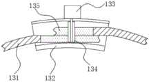
具体地,第二连接件130包括两个第二弧板131、第二套环132、旋钮133和齿轮134,两个第二弧板131分别转动安装于两个支撑轴112的外侧,两个第二弧板131分别处于两个第一弧板121的外侧,两个第二弧板131的一端侧部均设置有齿条135,旋钮133转动安装于第二套环132的侧部,齿轮134安装于旋钮133的侧部,齿轮134处于第二套环132的内部,两个齿条135分别插入第二套环132的内侧,两个齿条135均分别与齿轮134相啮合,具体使用时,通过转动旋钮133进而使得齿轮134转动,进而带动齿条135移动,齿条135的移动带动第二弧板131在第二套环132的内部滑动,进而简便的实现距离的调整,满足多个不同尺寸头型的使用。Specifically, the second connecting
具体地,第三连接件140包括两个第三弧板141和柔性布条142,两个第三弧板141分别转动安装于两个支撑轴112的外侧,两个第三弧板141的端部通过柔性布条142相连,第三弧板141和柔性布条142的配合,便于在第二连接件130调整的过程中,尺寸跟随调整。Specifically, the third connecting
具体地,调节件240包括阻尼转轴241、支架242、滑块243和弹片244,阻尼转轴241安装于红外探测器230的侧部,支架242安装于阻尼转轴241的侧部,滑块243滑动安装于支架242的侧部,弹片244安装于滑块243的侧部,弹片244与支架242的侧壁相抵触,放大镜本体250安装于滑块243的侧部,具体使用时,通过拉动弹片244,使得弹片244与支架242脱离,进而滑动滑块,即可实现放大镜本体250位置的调整,通过阻尼转轴241调整支架242的角度,可进一步的调整放大镜本体250的位置,便于更好调整位置。Specifically, the adjusting
具体地,弹片244的侧部开设有缺口2441,支架242的侧部安装有与缺口2441配合的若干凸起部2421,缺口2441和凸起部2421的配合,便于更好的卡紧。Specifically, the side of the
具体地,支撑件310包括万向旋转平台311和连接架312,万向旋转平台311可拆卸的安装于一个支撑块110的侧部,连接架312安装于万向旋转平台311的旋转端,VR投影仪320安装于连接架312的侧部,具体使用时,万向旋转平台311方便转动,便于对VR投影仪320投影的角度进行调整,方便后续的投影图像与放大镜本体250的成像拟合。Specifically, the supporting
具体地,盒体410的侧部安装有电源接头411,电源接头411与蓄电池420电性相连,电源接头411方便为蓄电池420充电。Specifically, a
具体地,VR投影仪320和处理器440均分别电性连接有无线传输模块,两个无线传输模块信号相连,利用无线传输模块进行无线传输,无线传输模块可以设置为蓝牙。Specifically, both the
工作原理:利用第一连接件120、第二连接件130和第三连接件140的配合,可以牢固的佩戴在头部,且能根据需求调整大小,满足多种头型医生的使用;利用镜片220方便显示放大镜本体250放大后的物像,并接收VR投影仪320发出的投影,红外探测器230将患者身体红外辐射能转换为电信号,便于后续处理器440的处理,通过放大镜本体250对患者的患处进行放大,便于医生观察和后续手术,调节件240用于调整放大镜本体250的位置,便于适配不同眼距医生的使用;蓄电池420用于对各电气元件供电,按钮开关430便于打开设备,处理器440用于对接收的红外探测器230发出的电信号进行处理,并生成视频信号,然后将视频信号传输给VR投影仪320,VR投影仪320将接收的视频信号投影在镜片220上,并与放大镜本体250放大的物像拟合重叠,从而非常直观地定位信号最高点,即为穿支动脉的位置,便于进行游离皮瓣手术亦或是带穿支血管蒂皮瓣手术。Working principle: Using the cooperation of the
以上所述仅为本发明的优选实施例而已,并不用于限制本发明,对于本领域的技术人员来说,本发明可以有各种更改和变化。凡在本发明的精神和原则之内,所作的任何修改、等同替换、改进等,均应包含在本发明的保护范围之内。The above descriptions are only preferred embodiments of the present invention, and are not intended to limit the present invention. For those skilled in the art, the present invention may have various modifications and changes. Any modification, equivalent replacement, improvement, etc. made within the spirit and principle of the present invention shall be included within the protection scope of the present invention.
Claims (10)
Translated fromChinesePriority Applications (1)
| Application Number | Priority Date | Filing Date | Title |
|---|---|---|---|
| CN202011064746.0ACN112137732A (en) | 2020-09-30 | 2020-09-30 | Medical operation magnifying glass based on infrared ray thermoforming technique |
Applications Claiming Priority (1)
| Application Number | Priority Date | Filing Date | Title |
|---|---|---|---|
| CN202011064746.0ACN112137732A (en) | 2020-09-30 | 2020-09-30 | Medical operation magnifying glass based on infrared ray thermoforming technique |
Publications (1)
| Publication Number | Publication Date |
|---|---|
| CN112137732Atrue CN112137732A (en) | 2020-12-29 |
Family
ID=73952318
Family Applications (1)
| Application Number | Title | Priority Date | Filing Date |
|---|---|---|---|
| CN202011064746.0APendingCN112137732A (en) | 2020-09-30 | 2020-09-30 | Medical operation magnifying glass based on infrared ray thermoforming technique |
Country Status (1)
| Country | Link |
|---|---|
| CN (1) | CN112137732A (en) |
Citations (6)
| Publication number | Priority date | Publication date | Assignee | Title |
|---|---|---|---|---|
| WO2015172021A1 (en)* | 2014-05-09 | 2015-11-12 | Nazareth Godfrey | Portable surgical methods, systems, and apparatus |
| CN108490619A (en)* | 2018-05-17 | 2018-09-04 | 深圳职业技术学院 | A kind of wear-type VR glasses |
| US20180325618A1 (en)* | 2017-05-05 | 2018-11-15 | OrbisMV LLC | Surgical projection system and method |
| CN211433341U (en)* | 2019-08-08 | 2020-09-08 | 北京缙铖医疗科技有限公司 | Display helmet for endoscopic surgery |
| CN111631814A (en)* | 2020-06-11 | 2020-09-08 | 上海交通大学医学院附属第九人民医院 | Intraoperative blood vessel three-dimensional positioning navigation system and method |
| CN213758603U (en)* | 2020-09-30 | 2021-07-23 | 宁波市第一医院 | A medical surgical magnifying glass based on infrared thermoforming technology |
- 2020
- 2020-09-30CNCN202011064746.0Apatent/CN112137732A/enactivePending
Patent Citations (6)
| Publication number | Priority date | Publication date | Assignee | Title |
|---|---|---|---|---|
| WO2015172021A1 (en)* | 2014-05-09 | 2015-11-12 | Nazareth Godfrey | Portable surgical methods, systems, and apparatus |
| US20180325618A1 (en)* | 2017-05-05 | 2018-11-15 | OrbisMV LLC | Surgical projection system and method |
| CN108490619A (en)* | 2018-05-17 | 2018-09-04 | 深圳职业技术学院 | A kind of wear-type VR glasses |
| CN211433341U (en)* | 2019-08-08 | 2020-09-08 | 北京缙铖医疗科技有限公司 | Display helmet for endoscopic surgery |
| CN111631814A (en)* | 2020-06-11 | 2020-09-08 | 上海交通大学医学院附属第九人民医院 | Intraoperative blood vessel three-dimensional positioning navigation system and method |
| CN213758603U (en)* | 2020-09-30 | 2021-07-23 | 宁波市第一医院 | A medical surgical magnifying glass based on infrared thermoforming technology |
Similar Documents
| Publication | Publication Date | Title |
|---|---|---|
| JP2024160244A (en) | Medical imaging method using multiple arrays - Patents.com | |
| WO2020147691A1 (en) | Imaging system for surgical robot, and surgical robot | |
| CN204636276U (en) | A kind of wearing die cavity mirror virtual display system | |
| US12076088B2 (en) | Virtual reality-based portable nystagmography device and diagnostic test method using same | |
| CN106491076A (en) | Full-automatic fundus camera | |
| CN101889853B (en) | Three-dimensional endoscope system capable of rotating freely for angles | |
| JP6368005B1 (en) | Medical magnifier device | |
| JP2022154495A (en) | Medical head mount and medical optical lighting device | |
| CN213758603U (en) | A medical surgical magnifying glass based on infrared thermoforming technology | |
| CN204636299U (en) | A kind of portable infrared angiograph | |
| KR101740602B1 (en) | Vein viewer using near infrared ray | |
| CN112137732A (en) | Medical operation magnifying glass based on infrared ray thermoforming technique | |
| CN215937645U (en) | Novel mixed reality technique spinal surgery segment location device | |
| CN203524644U (en) | Handheld digital wide angle ophthalmoscope | |
| CN206729873U (en) | Full-automatic fundus camera | |
| EP3241487B1 (en) | Open retinoscope couplable to a smartphone | |
| WO2019103631A1 (en) | Portable gonioscope | |
| Muratore et al. | Image display in endoscopic surgery | |
| CN218652662U (en) | Infrared glasses for superficial venipuncture | |
| CN219000260U (en) | Optical coherence tomography apparatus with adjusting mechanism | |
| CN219871962U (en) | An improved new type of surgical glasses | |
| CN222708207U (en) | Wireless remote control external fixation lamp for ophthalmic examination | |
| CN213750517U (en) | Image diagnosis film-viewing device | |
| CN213640796U (en) | Otology inspection speculum | |
| CN108663793A (en) | A kind of medical micrurgy equipment |
Legal Events
| Date | Code | Title | Description |
|---|---|---|---|
| PB01 | Publication | ||
| PB01 | Publication | ||
| SE01 | Entry into force of request for substantive examination | ||
| SE01 | Entry into force of request for substantive examination |