CN112136094A - Depth-based foveated rendering for display systems - Google Patents
Depth-based foveated rendering for display systemsDownload PDFInfo
- Publication number
- CN112136094A CN112136094ACN201980031920.0ACN201980031920ACN112136094ACN 112136094 ACN112136094 ACN 112136094ACN 201980031920 ACN201980031920 ACN 201980031920ACN 112136094 ACN112136094 ACN 112136094A
- Authority
- CN
- China
- Prior art keywords
- resolution
- user
- virtual object
- light
- display system
- Prior art date
- Legal status (The legal status is an assumption and is not a legal conclusion. Google has not performed a legal analysis and makes no representation as to the accuracy of the status listed.)
- Pending
Links
Images


Classifications
- G—PHYSICS
- G06—COMPUTING OR CALCULATING; COUNTING
- G06F—ELECTRIC DIGITAL DATA PROCESSING
- G06F3/00—Input arrangements for transferring data to be processed into a form capable of being handled by the computer; Output arrangements for transferring data from processing unit to output unit, e.g. interface arrangements
- G06F3/01—Input arrangements or combined input and output arrangements for interaction between user and computer
- G06F3/011—Arrangements for interaction with the human body, e.g. for user immersion in virtual reality
- G—PHYSICS
- G09—EDUCATION; CRYPTOGRAPHY; DISPLAY; ADVERTISING; SEALS
- G09G—ARRANGEMENTS OR CIRCUITS FOR CONTROL OF INDICATING DEVICES USING STATIC MEANS TO PRESENT VARIABLE INFORMATION
- G09G5/00—Control arrangements or circuits for visual indicators common to cathode-ray tube indicators and other visual indicators
- G09G5/36—Control arrangements or circuits for visual indicators common to cathode-ray tube indicators and other visual indicators characterised by the display of a graphic pattern, e.g. using an all-points-addressable [APA] memory
- G09G5/39—Control of the bit-mapped memory
- G09G5/391—Resolution modifying circuits, e.g. variable screen formats
- G—PHYSICS
- G02—OPTICS
- G02B—OPTICAL ELEMENTS, SYSTEMS OR APPARATUS
- G02B27/00—Optical systems or apparatus not provided for by any of the groups G02B1/00 - G02B26/00, G02B30/00
- G02B27/0093—Optical systems or apparatus not provided for by any of the groups G02B1/00 - G02B26/00, G02B30/00 with means for monitoring data relating to the user, e.g. head-tracking, eye-tracking
- G—PHYSICS
- G02—OPTICS
- G02B—OPTICAL ELEMENTS, SYSTEMS OR APPARATUS
- G02B27/00—Optical systems or apparatus not provided for by any of the groups G02B1/00 - G02B26/00, G02B30/00
- G02B27/01—Head-up displays
- G02B27/017—Head mounted
- G02B27/0172—Head mounted characterised by optical features
- G—PHYSICS
- G06—COMPUTING OR CALCULATING; COUNTING
- G06F—ELECTRIC DIGITAL DATA PROCESSING
- G06F3/00—Input arrangements for transferring data to be processed into a form capable of being handled by the computer; Output arrangements for transferring data from processing unit to output unit, e.g. interface arrangements
- G06F3/01—Input arrangements or combined input and output arrangements for interaction between user and computer
- G06F3/011—Arrangements for interaction with the human body, e.g. for user immersion in virtual reality
- G06F3/013—Eye tracking input arrangements
- G—PHYSICS
- G06—COMPUTING OR CALCULATING; COUNTING
- G06F—ELECTRIC DIGITAL DATA PROCESSING
- G06F3/00—Input arrangements for transferring data to be processed into a form capable of being handled by the computer; Output arrangements for transferring data from processing unit to output unit, e.g. interface arrangements
- G06F3/14—Digital output to display device ; Cooperation and interconnection of the display device with other functional units
- G06F3/147—Digital output to display device ; Cooperation and interconnection of the display device with other functional units using display panels
- G—PHYSICS
- G06—COMPUTING OR CALCULATING; COUNTING
- G06T—IMAGE DATA PROCESSING OR GENERATION, IN GENERAL
- G06T15/00—3D [Three Dimensional] image rendering
- G—PHYSICS
- G06—COMPUTING OR CALCULATING; COUNTING
- G06T—IMAGE DATA PROCESSING OR GENERATION, IN GENERAL
- G06T5/00—Image enhancement or restoration
- G06T5/70—Denoising; Smoothing
- G—PHYSICS
- G02—OPTICS
- G02B—OPTICAL ELEMENTS, SYSTEMS OR APPARATUS
- G02B27/00—Optical systems or apparatus not provided for by any of the groups G02B1/00 - G02B26/00, G02B30/00
- G02B27/01—Head-up displays
- G02B27/0101—Head-up displays characterised by optical features
- G02B2027/0147—Head-up displays characterised by optical features comprising a device modifying the resolution of the displayed image
- G—PHYSICS
- G06—COMPUTING OR CALCULATING; COUNTING
- G06T—IMAGE DATA PROCESSING OR GENERATION, IN GENERAL
- G06T2210/00—Indexing scheme for image generation or computer graphics
- G06T2210/36—Level of detail
- G—PHYSICS
- G09—EDUCATION; CRYPTOGRAPHY; DISPLAY; ADVERTISING; SEALS
- G09G—ARRANGEMENTS OR CIRCUITS FOR CONTROL OF INDICATING DEVICES USING STATIC MEANS TO PRESENT VARIABLE INFORMATION
- G09G2320/00—Control of display operating conditions
- G09G2320/02—Improving the quality of display appearance
- G09G2320/0261—Improving the quality of display appearance in the context of movement of objects on the screen or movement of the observer relative to the screen
- G—PHYSICS
- G09—EDUCATION; CRYPTOGRAPHY; DISPLAY; ADVERTISING; SEALS
- G09G—ARRANGEMENTS OR CIRCUITS FOR CONTROL OF INDICATING DEVICES USING STATIC MEANS TO PRESENT VARIABLE INFORMATION
- G09G2320/00—Control of display operating conditions
- G09G2320/06—Adjustment of display parameters
- G09G2320/0606—Manual adjustment
- G—PHYSICS
- G09—EDUCATION; CRYPTOGRAPHY; DISPLAY; ADVERTISING; SEALS
- G09G—ARRANGEMENTS OR CIRCUITS FOR CONTROL OF INDICATING DEVICES USING STATIC MEANS TO PRESENT VARIABLE INFORMATION
- G09G2320/00—Control of display operating conditions
- G09G2320/06—Adjustment of display parameters
- G09G2320/0613—The adjustment depending on the type of the information to be displayed
- G—PHYSICS
- G09—EDUCATION; CRYPTOGRAPHY; DISPLAY; ADVERTISING; SEALS
- G09G—ARRANGEMENTS OR CIRCUITS FOR CONTROL OF INDICATING DEVICES USING STATIC MEANS TO PRESENT VARIABLE INFORMATION
- G09G2340/00—Aspects of display data processing
- G09G2340/04—Changes in size, position or resolution of an image
- G09G2340/0407—Resolution change, inclusive of the use of different resolutions for different screen areas
- G09G2340/0428—Gradation resolution change
- G—PHYSICS
- G09—EDUCATION; CRYPTOGRAPHY; DISPLAY; ADVERTISING; SEALS
- G09G—ARRANGEMENTS OR CIRCUITS FOR CONTROL OF INDICATING DEVICES USING STATIC MEANS TO PRESENT VARIABLE INFORMATION
- G09G2340/00—Aspects of display data processing
- G09G2340/12—Overlay of images, i.e. displayed pixel being the result of switching between the corresponding input pixels
- G—PHYSICS
- G09—EDUCATION; CRYPTOGRAPHY; DISPLAY; ADVERTISING; SEALS
- G09G—ARRANGEMENTS OR CIRCUITS FOR CONTROL OF INDICATING DEVICES USING STATIC MEANS TO PRESENT VARIABLE INFORMATION
- G09G2354/00—Aspects of interface with display user
- G—PHYSICS
- G09—EDUCATION; CRYPTOGRAPHY; DISPLAY; ADVERTISING; SEALS
- G09G—ARRANGEMENTS OR CIRCUITS FOR CONTROL OF INDICATING DEVICES USING STATIC MEANS TO PRESENT VARIABLE INFORMATION
- G09G2360/00—Aspects of the architecture of display systems
- G09G2360/14—Detecting light within display terminals, e.g. using a single or a plurality of photosensors
- G09G2360/144—Detecting light within display terminals, e.g. using a single or a plurality of photosensors the light being ambient light
Landscapes
- Engineering & Computer Science (AREA)
- Theoretical Computer Science (AREA)
- Physics & Mathematics (AREA)
- General Physics & Mathematics (AREA)
- General Engineering & Computer Science (AREA)
- Human Computer Interaction (AREA)
- Optics & Photonics (AREA)
- Computer Hardware Design (AREA)
- Computer Graphics (AREA)
- User Interface Of Digital Computer (AREA)
- Processing Or Creating Images (AREA)
- Controls And Circuits For Display Device (AREA)
- Testing, Inspecting, Measuring Of Stereoscopic Televisions And Televisions (AREA)
Abstract
Description
Translated fromChinese相关申请的交叉引用CROSS-REFERENCE TO RELATED APPLICATIONS
本申请要求于2018年3月16日提交的美国临时申请No.62/644,366的优先权的权益,其整体内容通过引用并入本文。This application claims the benefit of priority to US Provisional Application No. 62/644,366, filed March 16, 2018, the entire contents of which are incorporated herein by reference.
援引并入incorporated by reference
本申请通过引用并入下列专利申请和公开中的每一个的全部内容:2014年11月27日提交的美国申请No.14/555,585,其于2015年7月23日被公开为美国公开No.2015/0205126;2015年4月18日提交的美国申请No.14/690,401,其于2015年10月22日被公开为美国公开No.2015/0302652;2014年3月14日提交的美国申请No.14/212,961,现为2016年8月16日发布的美国专利No.9,417,452;2014年7月14日提交的美国申请No.14/331,218,其于2015年10月29日被公开为美国公开No.2015/0309263;2018年2月22日提交的美国申请No.15/902,927;2017年3月22日提交的美国临时申请No.62/475,012;以及2017年8月1日提交的美国临时申请No.62/539,934。This application incorporates by reference the entire contents of each of the following patent applications and publications: US Application No. 14/555,585, filed November 27, 2014, published as US Publication No. 23, 2015 2015/0205126; US Application No. 14/690,401, filed on April 18, 2015, published as US Publication No. 2015/0302652 on October 22, 2015; US Application No. 2015/0302652, filed on March 14, 2014 .14/212,961, now U.S. Patent No. 9,417,452, issued Aug. 16, 2016; U.S. Application No. 14/331,218, filed Jul. 14, 2014, published Oct. 29, 2015 US Application No. 15/902,927, filed February 22, 2018; US Provisional Application No. 62/475,012, filed March 22, 2017; and US Provisional Application No. 62/475,012, filed August 1, 2017 Application No. 62/539,934.
技术领域technical field
本公开涉及显示系统,其包括增强现实成像和可视化系统。The present disclosure relates to display systems including augmented reality imaging and visualization systems.
背景技术Background technique
现代计算和显示技术促进了用于所谓的“虚拟现实”或“增强现实”体验的系统的开发,其中数字再现的图像或其部分以它们看起来真实或可被感知为真实的方式呈现给用户。虚拟现实或“VR”场景通常涉及数字或虚拟图像信息的呈现,而对其它实际真实世界视觉输入没有透明性;增强现实或“AR”场景通常涉及将数字或虚拟图像信息呈现为对用户周围的实际世界的可视化的增强。混合现实或“MR”场景是一种AR场景,并且通常涉及集成到自然世界中并对自然世界做出响应的虚拟对象。例如,MR场景可以包括看起来被真实世界中的对象阻挡或者以其它方式被感知为与真实世界中的对象交互的AR图像内容。Modern computing and display technologies have facilitated the development of systems for so-called "virtual reality" or "augmented reality" experiences, in which digitally reproduced images or parts thereof are presented to the user in such a way that they appear real or can be perceived as real . Virtual reality or "VR" scenes typically involve the presentation of digital or virtual image information without transparency to other actual real-world visual input; augmented reality or "AR" scenes typically involve the presentation of digital or virtual image information to the user's surroundings. Real-world visualization enhancements. A mixed reality or "MR" scene is an AR scene and typically involves virtual objects that are integrated into and respond to the natural world. For example, an MR scene may include AR image content that appears to be occluded by, or otherwise perceived as interacting with, objects in the real world.
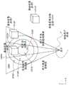
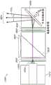
参考图1,描绘了增强现实场景10。AR技术的用户看到以人、树、背景中的建筑物和混凝土平台30为特征的真实世界公园状设置20。用户还感知到他/她“看到”“虚拟内容”,例如站在真实世界平台30上的机器人像40,以及正飞翔的卡通状化身角色50,其似乎是大黄蜂的拟人化。这些元素50、40是“虚拟的”因为它们不存在于真实世界中。因为人类视觉感知系统是复杂的,所以产生促进虚拟图像元素以及其它虚拟或真实世界的图像元素的舒适、感觉自然、丰富呈现的AR技术是有挑战性的。Referring to Figure 1, an augmented
本文公开的系统和方法解决了与AR和VR技术有关的各种挑战。The systems and methods disclosed herein address various challenges associated with AR and VR technologies.
发明内容SUMMARY OF THE INVENTION
根据一些实施例,一种系统包括一个或多个处理器以及存储指令的一个或多个计算机存储介质,所述指令在由一个或多个处理器执行时使一个或多个处理器执行操作。所述操作包括基于通过一个或多个传感器检测的信息来监视用户的眼睛运动。基于眼睛运动来确定用户的眼睛正在注视的注视点,其中,注视点是用户视场中的三维位置。所述操作包括获得与将呈现给用户的一个或多个虚拟对象相关联的位置信息,该位置信息指示虚拟对象的三维位置。所述操作还包括至少部分地基于至少一个虚拟对象与注视点的接近度来调整至少一个虚拟对象的分辨率。所述操作还包括使虚拟对象通过显示器呈现给用户,其中,根据调整后的分辨率渲染至少一个虚拟对象。According to some embodiments, a system includes one or more processors and one or more computer storage media storing instructions that, when executed by the one or more processors, cause the one or more processors to perform operations. The operations include monitoring eye movement of the user based on information detected by one or more sensors. The gaze point at which the user's eyes are looking is determined based on the eye movement, where the gaze point is a three-dimensional location in the user's field of view. The operations include obtaining location information associated with one or more virtual objects to be presented to the user, the location information indicating a three-dimensional location of the virtual objects. The operations also include adjusting a resolution of the at least one virtual object based at least in part on a proximity of the at least one virtual object to the gaze point. The operations also include presenting the virtual object to the user through the display, wherein the at least one virtual object is rendered according to the adjusted resolution.
根据一些实施例,显示系统包括:显示装置,其被配置为向用户呈现虚拟内容;一个或多个处理器;以及存储指令的一个或多个计算机存储介质,所述指令在由系统执行时,使系统执行操作。所述操作包括监视与用户的眼睛运动相关联的信息。基于所监视的信息来确定显示装置的显示平截头体(frustum)内的注视点,该注视点指示被用户的眼睛注视的三维位置。所述操作还包括基于所确定的注视点在显示平截头体内的三维位置处呈现虚拟内容,其中,基于虚拟内容与注视点的接近度来在分辨率方面调整虚拟内容。According to some embodiments, a display system includes: a display device configured to present virtual content to a user; one or more processors; and one or more computer storage media storing instructions that, when executed by the system, Causes the system to perform an action. The operations include monitoring information associated with eye movements of the user. Based on the monitored information, a gaze point within a display frustum of the display device is determined, the gaze point indicating the three-dimensional location being gazed at by the user's eyes. The operations also include presenting the virtual content at a three-dimensional location within the display frustum based on the determined gaze point, wherein the virtual content is adjusted in resolution based on a proximity of the virtual content to the gaze point.
根据一些其他实施例,一种方法包括基于通过一个或多个传感器检测到的信息来监视用户的眼睛运动。基于眼睛运动来确定用户的眼睛正在注视的注视点,其中,注视点是用户的视场中的三维位置。获得与要呈现给用户的一个或多个虚拟对象相关联的位置信息,该位置信息指示虚拟对象的三维位置。至少部分地基于至少一个虚拟对象与注视点的接近度来调整至少一个虚拟对象的分辨率。该方法还包括使虚拟对象通过显示器呈现给用户,其中,根据调整后的分辨率渲染至少一个虚拟对象。According to some other embodiments, a method includes monitoring eye movement of a user based on information detected by one or more sensors. The gaze point at which the user's eyes are looking is determined based on the eye movement, where the gaze point is a three-dimensional location in the user's field of view. Location information is obtained associated with one or more virtual objects to be presented to the user, the location information indicating the three-dimensional locations of the virtual objects. The resolution of the at least one virtual object is adjusted based, at least in part, on a proximity of the at least one virtual object to the gaze point. The method also includes presenting the virtual object to the user through the display, wherein the at least one virtual object is rendered according to the adjusted resolution.
根据一些实施例,一种显示系统包括:被配置为安装在用户的头部上的框架;被配置为输出光以形成图像的光调制系统;以及附接到框架一个多个波导,该一个或多个波导被配置为接收来自光调制系统的光并跨该一个或多个波导的表面输出光。该系统还包括一个或多个处理器,以及存储指令的一个或多个计算机存储介质,所述指令在由一个或多个处理器执行时使一个或多个处理器执行各种操作。所述操作包括确定到达用户的眼睛的视网膜的光量;以及基于到达视网膜的光量来调整要呈现给用户的虚拟内容的分辨率。According to some embodiments, a display system includes: a frame configured to be mounted on a user's head; a light modulation system configured to output light to form an image; and a plurality of waveguides attached to the frame, the one or The plurality of waveguides are configured to receive light from the light modulation system and output the light across the surface of the one or more waveguides. The system also includes one or more processors, and one or more computer storage media storing instructions that, when executed by the one or more processors, cause the one or more processors to perform various operations. The operations include determining an amount of light reaching the retina of the user's eye; and adjusting a resolution of virtual content to be presented to the user based on the amount of light reaching the retina.
根据一些其他实施例,一种显示系统包括一个或多个处理器;以及存储指令的一个或多个计算机存储介质。当指令由一个或多个处理器执行时,它们使一个或多个处理器执行各种操作。所述操作包括确定到达显示系统的用户的眼睛的视网膜的光量;以及基于到达视网膜的光量来调整要呈现给用户的虚拟内容的分辨率。According to some other embodiments, a display system includes one or more processors; and one or more computer storage media storing instructions. When executed by one or more processors, they cause the one or more processors to perform various operations. The operations include determining an amount of light reaching a retina of an eye of a user of the display system; and adjusting a resolution of virtual content to be presented to the user based on the amount of light reaching the retina.
根据一些实施例,一种方法由包括一个或多个处理器和可头戴显示器的显示系统执行。该方法包括确定到达显示系统的用户的眼睛的视网膜的光量;以及基于到达视网膜的光量来调整要呈现给用户的虚拟内容的分辨率。According to some embodiments, a method is performed by a display system including one or more processors and a head mountable display. The method includes determining an amount of light reaching a retina of an eye of a user of the display system; and adjusting a resolution of virtual content to be presented to the user based on the amount of light reaching the retina.
根据一些其他实施例,一种显示系统包括:被配置为安装在用户头部上的框架;和光调制系统;一个或多个波导;一个或多个处理器;存储指令的一个或多个计算机存储介质。光调制系统被配置为输出光以形成图像。一个或多个波导被附接到框架,并且被配置为接收来自光调制系统的光并跨该一个或多个波导的表面输出光。一个或多个计算机存储介质存储指令,所述指令在由一个或多个处理器执行时使一个或多个处理器执行各种操作。所述操作包括基于以下各项来调整形成虚拟内容的分量颜色图像的分辨率:虚拟内容与用户注视点的接近度;以及分量颜色图像的颜色。分量颜色图像中的至少一个与另一种颜色的分量颜色图像的分辨率不同。According to some other embodiments, a display system includes: a frame configured to be mounted on a user's head; and a light modulation system; one or more waveguides; one or more processors; medium. The light modulation system is configured to output light to form an image. One or more waveguides are attached to the frame and are configured to receive light from the light modulation system and output the light across the surface of the one or more waveguides. One or more computer storage media store instructions that, when executed by one or more processors, cause the one or more processors to perform various operations. The operations include adjusting a resolution of a component color image forming the virtual content based on a proximity of the virtual content to a user's gaze point; and a color of the component color image. At least one of the component color images has a different resolution than the component color image of the other color.
根据其他实施例,一种显示系统包括一个或多个处理器;存储指令的一个或多个计算机存储介质。当指令由一个或多个处理器执行时,它们使一个或多个处理器执行各种操作。所述操作包括基于以下各项来调整形成虚拟内容的分量颜色图像的分辨率:虚拟内容与用户注视点的接近度;以及分量颜色图像的颜色,其中,分量颜色图像中的至少一个与另一种颜色的分量颜色图像的分辨率不同。According to other embodiments, a display system includes one or more processors; one or more computer storage media storing instructions. When executed by one or more processors, they cause the one or more processors to perform various operations. The operations include adjusting a resolution of a component color image forming the virtual content based on: proximity of the virtual content to a user's gaze point; and a color of the component color image, wherein at least one of the component color images is different from the other The component color images of each color have different resolutions.
根据一些其他实施例,一种方法由包括一个或多个处理器和可头戴显示器的显示系统执行。该方法包括基于以下各项来调整形成虚拟内容的分量颜色图像的分辨率:虚拟内容与用户注视点的接近度;以及分量颜色图像的颜色,其中,分量颜色图像中的至少一个与另一种颜色的分量颜色图像的分辨率不同。According to some other embodiments, a method is performed by a display system including one or more processors and a head mountable display. The method includes adjusting a resolution of a component color image forming the virtual content based on: proximity of the virtual content to a user's gaze point; and a color of the component color image, wherein at least one of the component color images is different from the other The components of a color image have different resolutions.
根据其他实施例,一种显示系统包括:图像源,其包括用于提供第一图像流和第二图像流的空间光调制器;观看组件;与图像源通信的一个或多个处理器;存储指令的一个或多个计算机存储介质,当指令由一个或多个处理器执行时,使一个或多个处理器执行各种操作。观看组件包括用于接收来自图像源的第一和第二图像流并将第一和第二图像流输出给用户的光导光学器件。由一个或多个处理器执行的各种操作包括:使图像源向观看组件输出第一图像流,其中,由第一图像流形成的图像具有第一像素密度;以及使图像源向观看组件输出第二图像流。由第二图像流形成的图像具有大于第一像素密度的第二像素密度,并且对应于由第一图像流提供的图像的部分。由第二图像流形成的图像覆盖由第一图像流提供的视场的对应部分。According to other embodiments, a display system includes: an image source including a spatial light modulator for providing a first image stream and a second image stream; a viewing component; one or more processors in communication with the image source; storage One or more computer storage media of instructions that, when executed by one or more processors, cause the one or more processors to perform various operations. The viewing assembly includes light guide optics for receiving first and second image streams from an image source and outputting the first and second image streams to a user. The various operations performed by the one or more processors include: causing the image source to output a first stream of images to a viewing component, wherein an image formed by the first image stream has a first pixel density; and causing the image source to output to the viewing component second image stream. The image formed by the second image stream has a second pixel density greater than the first pixel density and corresponds to the portion of the image provided by the first image stream. The image formed by the second image stream covers a corresponding portion of the field of view provided by the first image stream.
根据一些实施例,可佩戴显示系统可以包括具有圆偏振旋向性相关的放大率的无焦放大器。无焦放大器可以包括:第一固定焦距透镜元件;第一几何相位透镜,其对于入射的圆偏振光的第一旋向性表现出正屈光力,而对于入射的圆偏振光的第二旋向性表现出负屈光力;以及第二个几何相位透镜。According to some embodiments, a wearable display system may include an afocal amplifier with circular polarization handedness dependent magnification. The afocal amplifier may include: a first fixed focal length lens element; a first geometric phase lens exhibiting positive refractive power for a first handedness of incident circularly polarized light and a second handedness for incident circularly polarized light exhibit negative refractive power; and a second geometric phase lens.
根据一些其他实施例,一种用于可佩戴图像投射器的光学子系统可以包括偏振选择性反射器和围绕偏振选择性反射器定位的一组四个透镜元件。According to some other embodiments, an optical subsystem for a wearable image projector may include a polarization selective reflector and a set of four lens elements positioned around the polarization selective reflector.
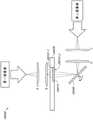
根据一些其他实施例,一种用于将图像投射到用户的眼睛的显示系统可以包括目镜。目镜可包括波导和光学耦合到波导的耦入光栅。该显示系统还可以包括第一图像源,该第一图像源被配置为投射与第一图像流相关联的第一光束。第一图像流可以具有第一视场并且可以入射在耦入光栅的第一表面上。第一光束的一部分可以通过耦入光栅耦合到波导中,以将第一图像流定位在距用户眼睛的固定位置。该显示系统还可以包括第二图像源,该第二图像源被配置为投射与第二图像流相关联的第二光束。第二图像流可以具有比第一视场窄的第二视场。该显示系统还可以包括扫描镜,该扫描镜被配置为接收和反射第二光束,使得第二光束入射在耦入光栅的与第一表面相对的第二表面上。第二光束的一部分可以通过耦入光栅耦合到波导中。该显示系统还可以包括被配置为检测用户的眼睛的运动的眼睛视线跟踪器,以及与眼睛视线跟踪器和扫描镜通信的控制电路。控制电路可以被配置为定位扫描镜,使得第二图像流的位置根据检测到的用户眼睛的移动而移动。According to some other embodiments, a display system for projecting an image to a user's eye may include an eyepiece. The eyepiece may include a waveguide and an in-coupling grating optically coupled to the waveguide. The display system may also include a first image source configured to project a first light beam associated with the first image stream. The first image stream can have a first field of view and can be incident on a first surface coupled into the grating. A portion of the first beam may be coupled into the waveguide through the coupling grating to position the first image stream at a fixed location from the user's eye. The display system may also include a second image source configured to project a second light beam associated with the second image stream. The second image stream may have a second field of view that is narrower than the first field of view. The display system may also include a scanning mirror configured to receive and reflect the second light beam such that the second light beam is incident on a second surface of the coupled-in grating opposite the first surface. A portion of the second beam may be coupled into the waveguide through the coupling grating. The display system may also include an eye gaze tracker configured to detect movement of the user's eyes, and a control circuit in communication with the eye gaze tracker and the scanning mirror. The control circuit may be configured to position the scanning mirror such that the position of the second image stream moves according to the detected movement of the user's eye.
根据一些其他实施例,一种用于将图像投射到用户的眼睛的显示系统可以包括目镜。目镜可以包括波导和光学耦合到波导的耦入光栅。该显示系统还可以包括图像源,该图像源被配置为投射处于第一偏振的与第一图像流相关联的第一光束,以及处于不同于第一偏振的第二偏振的与第二图像流相关联的第二光束。第一图像流可以具有第一视场,并且第二图像流可以具有比第一视场窄的第二视场。第一光束和第二光束可以被复用。该显示系统还可以包括偏振分束器,该偏振分束器被配置为接收并沿着第一光路反射第一光束,以及接收并沿着第二光路透射第二光束。该显示系统还可以包括第一光学反射器,该第一光学反射器沿着第一光路定位并被配置为接收和反射第一光束,使得第一光束入射在耦入光栅的第一表面上。第一光束的一部分可以通过耦入光栅耦合到波导中,以将第一图像流定位在距用户眼睛的固定位置。该显示系统还可以包括扫描镜,该扫描镜沿着第二光路设置并且被配置为接收和反射第二光束;以及第二光学反射器,其沿着第二光路位于扫描镜的下游。第二光学反射器可以被配置为接收和反射第二光束,使得第二光束入射在耦入光栅的与第一表面相对的第二表面上。第二光束的一部分可以通过耦入光栅耦合到波导中。该显示系统还可以包括被配置为检测用户的眼睛的移动的眼睛视线跟踪器,以及与眼睛视线跟踪器和扫描镜通信的控制电路。控制电路可以被配置为定位扫描镜,使得第二图像流的位置根据检测到的用户眼睛的移动而移动。According to some other embodiments, a display system for projecting an image to a user's eye may include an eyepiece. The eyepiece may include a waveguide and an in-coupling grating optically coupled to the waveguide. The display system may also include an image source configured to project a first light beam in a first polarization associated with the first image stream, and a second polarization associated with the second image stream in a second polarization different from the first polarization the associated second beam. The first image stream may have a first field of view, and the second image stream may have a second field of view that is narrower than the first field of view. The first beam and the second beam may be multiplexed. The display system may also include a polarizing beam splitter configured to receive and reflect the first light beam along the first optical path, and receive and transmit the second light beam along the second optical path. The display system may also include a first optical reflector positioned along the first optical path and configured to receive and reflect the first light beam such that the first light beam is incident on the first surface coupled into the grating. A portion of the first beam may be coupled into the waveguide through the coupling grating to position the first image stream at a fixed location from the user's eye. The display system may further include a scanning mirror disposed along the second optical path and configured to receive and reflect the second light beam; and a second optical reflector positioned downstream of the scanning mirror along the second optical path. The second optical reflector may be configured to receive and reflect the second light beam such that the second light beam is incident on a second surface of the coupling-in grating opposite the first surface. A portion of the second beam may be coupled into the waveguide through the coupling grating. The display system may also include an eye gaze tracker configured to detect movement of the user's eyes, and a control circuit in communication with the eye gaze tracker and the scanning mirror. The control circuit may be configured to position the scanning mirror such that the position of the second image stream moves according to the detected movement of the user's eye.
根据一些其他实施例,一种用于将图像投射到用户的眼睛的显示系统可以包括波导;图像源,该图像源被配置为投射处于第一偏振的与第一图像流相关联的第一光束以及处于不同于第一偏振的第二偏振的与第二图像流相关联的第二光束。第一图像流可以具有第一视场,并且第二图像流具有比第一视场窄的第二视场。第一光束和第二光束可以被复用。该显示系统还可以包括偏振分束器,该偏振分束器被配置为接收并沿着第一光路反射第一光束,以及接收并沿着第二光路透射第二光束。该显示系统还可以包括第一耦入棱镜,其沿着第一光路并且邻近波导的第一表面定位。该第一耦入棱镜可以被配置为将第一光束的一部分耦合到波导中,以将第一图像流定位到距用户的眼睛的固定位置。该显示系统还可以包括扫描镜,该扫描镜沿着第二光路设置并且被配置为接收和反射第二光束。该显示系统还可以包括第二耦入棱镜,该第二耦入棱镜沿着第二光路位于扫描镜的下游并且邻近与波导的第一表面相对的波导的第二表面。第二耦入棱镜可以被配置为将第二光束的一部分耦合到波导中。该显示系统还可以包括被配置为检测用户的眼睛的移动的眼睛视线跟踪器,以及与眼睛视线跟踪器和扫描镜通信的控制电路。控制电路可以被配置为定位扫描镜,使得第二图像流的位置根据检测到的用户眼睛的移动而移动。According to some other embodiments, a display system for projecting an image to an eye of a user may include a waveguide; an image source configured to project a first light beam associated with a first image stream in a first polarization and a second light beam associated with the second image stream in a second polarization different from the first polarization. The first image stream may have a first field of view, and the second image stream may have a second field of view that is narrower than the first field of view. The first beam and the second beam may be multiplexed. The display system may also include a polarizing beam splitter configured to receive and reflect the first light beam along the first optical path, and receive and transmit the second light beam along the second optical path. The display system may also include a first in-coupling prism positioned along the first optical path and adjacent to the first surface of the waveguide. The first in-coupling prism may be configured to couple a portion of the first light beam into the waveguide to position the first image stream at a fixed location from the user's eye. The display system may also include a scanning mirror disposed along the second optical path and configured to receive and reflect the second light beam. The display system may also include a second in-coupling prism located downstream of the scanning mirror along the second optical path and adjacent to a second surface of the waveguide opposite the first surface of the waveguide. The second in-coupling prism can be configured to couple a portion of the second beam into the waveguide. The display system may also include an eye gaze tracker configured to detect movement of the user's eyes, and a control circuit in communication with the eye gaze tracker and the scanning mirror. The control circuit may be configured to position the scanning mirror such that the position of the second image stream moves according to the detected movement of the user's eye.
根据实施例,一种用于将图像投射到用户的眼睛的显示系统包括图像源。图像源可以被配置成投射处于第一偏振的与第一图像流相关联的第一光束,以及处于与第一偏振不同的第二偏振的与第二图像流相关联的第二光束。第一图像流可以具有第一视场,并且第二图像流可以具有比第一视场窄的第二视场。第一光束和第二光束可以被复用。该显示系统还可以包括偏振分束器。偏振分束器可以被配置为接收并沿着第一光路朝向观看组件反射第一光束,以将第一图像流定位在距用户的眼睛的固定位置,并且接收并沿着第二光路透射第二光束。该显示系统还可以包括扫描镜,该扫描镜沿着第二光路设置并且被配置为接收第二光束并将其朝向观看组件反射。该显示系统还可以包括被配置为检测用户的眼睛的移动的眼睛视线跟踪器,以及与该眼睛视线跟踪器和扫描镜通信的控制电路。控制电路可以被配置为定位扫描镜,使得第二图像流的位置根据检测到的用户眼睛的移动而移动。According to an embodiment, a display system for projecting an image to a user's eye includes an image source. The image source may be configured to project a first light beam associated with the first image stream in a first polarization and a second light beam associated with the second image stream in a second polarization different from the first polarization. The first image stream may have a first field of view, and the second image stream may have a second field of view that is narrower than the first field of view. The first beam and the second beam may be multiplexed. The display system may also include a polarizing beam splitter. The polarizing beam splitter may be configured to receive and reflect the first light beam along the first optical path toward the viewing assembly to position the first image stream at a fixed location from the user's eye, and to receive and transmit the second optical beam along the second optical path beam. The display system may also include a scanning mirror disposed along the second optical path and configured to receive and reflect the second light beam toward the viewing assembly. The display system may also include an eye gaze tracker configured to detect movement of the user's eyes, and a control circuit in communication with the eye gaze tracker and the scanning mirror. The control circuit may be configured to position the scanning mirror such that the position of the second image stream moves according to the detected movement of the user's eye.
根据另一实施例,一种用于将图像投射到用户的眼睛的显示系统包括图像源。图像源可以被配置为投射与第一图像流相关联的第一光束和与第二图像流相关联的第二光束。第一图像流可以具有第一视场,并且第二图像流可以具有比第一视场窄的第二视场。第一光束和第二光束可以被复用。该显示系统还可以包括扫描镜,该扫描镜被配置为接收第一光束和第二光束并将其朝向观看组件反射,以投射第一图像流和第二图像流。该显示系统还可以包括被配置为检测用户的眼睛的移动的眼睛视线跟踪器,以及与眼睛视线跟踪器和扫描镜通信的控制电路。控制电路可以被配置为定位扫描镜,使得第一图像流的位置和第二图像流的位置根据检测到的用户眼睛的移动而移动。显示系统还可以包括设置在第一光束和第二光束的光路中的可切换光学元件。可切换光学元件可以被配置为被切换至针对第一光束的第一状态,使得第一光束以第一角放大率放大,并且被切换至针对第二光束的第二状态,使得第二光束以小于第一角放大率的第二角放大率被角度放大。According to another embodiment, a display system for projecting an image to a user's eye includes an image source. The image source may be configured to project a first light beam associated with the first image stream and a second light beam associated with the second image stream. The first image stream may have a first field of view, and the second image stream may have a second field of view that is narrower than the first field of view. The first beam and the second beam may be multiplexed. The display system may also include a scanning mirror configured to receive and reflect the first and second light beams toward the viewing assembly to project the first and second image streams. The display system may also include an eye gaze tracker configured to detect movement of the user's eyes, and a control circuit in communication with the eye gaze tracker and the scanning mirror. The control circuit may be configured to position the scanning mirror such that the position of the first image stream and the position of the second image stream move according to the detected movement of the user's eyes. The display system may also include switchable optical elements disposed in the optical paths of the first beam and the second beam. The switchable optical element may be configured to be switched to a first state for the first beam such that the first beam is amplified at a first angular magnification, and to be switched to a second state for the second beam such that the second beam is A second angular magnification less than the first angular magnification is angularly magnified.
在一些实施例中,一种显示系统包括一个或多个处理器和存储指令的一个或多个计算机存储介质,所述指令在由一个或多个处理器执行时使一个或多个处理器执行操作。所述操作包括确定用户的眼睛的注视点;获得与第一虚拟对象相关联的位置信息,该第一虚拟对象将通过显示装置呈现给用户;获取第一虚拟对象的分辨率修改参数;基于第一虚拟对象的位置信息和分辨率修改参数,识别渲染第一虚拟对象的特定分辨率,其中,该特定分辨率基于指定针对距注视点的对应距离的分辨率的分辨率分布;以及使得通过显示装置向用户呈现以所识别的分辨率渲染的第一虚拟对象。In some embodiments, a display system includes one or more processors and one or more computer storage media storing instructions that, when executed by the one or more processors, cause the one or more processors to execute operate. The operations include determining the gaze point of the user's eyes; obtaining position information associated with the first virtual object, which will be presented to the user through the display device; obtaining a resolution modification parameter of the first virtual object; position information and resolution modification parameters for a virtual object, identifying a specific resolution at which to render the first virtual object, wherein the specific resolution is based on a resolution distribution specifying a resolution for a corresponding distance from a gaze point; The device presents the user with the first virtual object rendered at the identified resolution.
在一些实施例中,提供了一种计算机实现的方法。该方法由具有一个或多个处理器的显示系统执行。该方法包括确定用户的眼睛的注视点;获得与第一虚拟对象相关联的位置信息,该第一虚拟对象将通过显示装置呈现给用户;获取第一虚拟对象的分辨率修改参数;基于第一虚拟对象的位置信息和分辨率修改参数,识别渲染第一虚拟对象的特定分辨率,其中,该特定分辨率基于指定针对距注视点的对应距离的分辨率的分辨率分布;以及使得通过显示装置向用户呈现以所识别的分辨率渲染的第一虚拟对象。In some embodiments, a computer-implemented method is provided. The method is performed by a display system having one or more processors. The method includes determining a gaze point of a user's eyes; obtaining position information associated with a first virtual object to be presented to the user through a display device; obtaining a resolution modification parameter of the first virtual object; position information and resolution modification parameters of the virtual object, identifying a specific resolution at which to render the first virtual object, wherein the specific resolution is based on a resolution distribution specifying a resolution for a corresponding distance from a gaze point; A first virtual object rendered at the identified resolution is presented to the user.
在一些实施例中,提供了一种非暂时性计算机存储介质。该计算机存储介质存储指令,当指令由具有一个或多个处理器的显示系统执行时,使一个或多个处理器执行操作。所述操作包括确定用户的眼睛的注视点;获得与第一虚拟对象相关联的位置信息,该第一虚拟对象将通过显示装置呈现给用户;获取第一虚拟对象的分辨率修改参数;基于第一虚拟对象的位置信息和分辨率修改参数,识别渲染第一虚拟对象的特定分辨率,其中,该特定分辨率基于指定针对距注视点的对应距离的分辨率的分辨率分布;以及使得通过显示装置向用户呈现以所识别的分辨率渲染的第一虚拟对象。In some embodiments, a non-transitory computer storage medium is provided. The computer storage medium stores instructions that, when executed by a display system having one or more processors, cause the one or more processors to perform operations. The operations include determining the gaze point of the user's eyes; obtaining position information associated with the first virtual object, which will be presented to the user through the display device; obtaining a resolution modification parameter of the first virtual object; position information and resolution modification parameters for a virtual object, identifying a specific resolution at which to render the first virtual object, wherein the specific resolution is based on a resolution distribution specifying a resolution for a corresponding distance from a gaze point; The device presents the user with the first virtual object rendered at the identified resolution.
下面提供实施例的附加示例。Additional examples of embodiments are provided below.
1.一种显示系统,包括:1. A display system comprising:
一个或多个处理器;以及one or more processors; and
一个或多个计算机存储介质,其存储指令,当所述指令由一个或多个处理器执行时,使所述一个或多个处理器执行以下操作:One or more computer storage media that store instructions that, when executed by one or more processors, cause the one or more processors to:
确定用户的眼睛的注视点;determine the gaze point of the user's eyes;
获得与第一虚拟对象相关联的位置信息,所述第一虚拟对象将通过显示装置呈现给用户;obtaining location information associated with a first virtual object to be presented to a user through a display device;
获取所述第一虚拟对象的分辨率修改参数;obtaining a resolution modification parameter of the first virtual object;
基于所述第一虚拟对象的所述位置信息和所述分辨率修改参数,识别渲染所述第一虚拟对象的特定分辨率,其中,所述特定分辨率基于指定针对距所述注视点的对应距离的分辨率的分辨率分布;以及Identifying a specific resolution at which to render the first virtual object based on the position information of the first virtual object and the resolution modification parameter, wherein the specific resolution is based on a specified pair of corresponding distances from the gaze point the resolution distribution of the resolution of the distance; and
使得通过所述显示装置向所述用户呈现以所识别的分辨率渲染的所述第一虚拟对象。The first virtual object rendered at the identified resolution is caused to be presented to the user by the display device.
2.根据示例1所述的显示系统,其中,所述分辨率修改参数包括与所述第一虚拟对象相关联的内容类型,其中,所述操作还包括:2. The display system of example 1, wherein the resolution modification parameter comprises a content type associated with the first virtual object, wherein the operations further comprise:
访问多个分辨率分布,所述分辨率分布与相应虚拟内容类型相关联;以及accessing a plurality of resolution profiles associated with respective virtual content types; and
基于所述第一虚拟对象的所述内容类型,从所述多个分辨率分布中选择特定分辨率分布,其中,所述特定分辨率包括所述特定分辨率分布。A specific resolution distribution is selected from the plurality of resolution distributions based on the content type of the first virtual object, wherein the specific resolution includes the specific resolution distribution.
3.根据示例3所述的显示系统,其中,基于与所述第一虚拟对象相关联的频谱,识别与所述第一虚拟对象相关联的所述虚拟内容类型。3. The display system of example 3, wherein the virtual content type associated with the first virtual object is identified based on a frequency spectrum associated with the first virtual object.
4.根据示例3所述的显示系统,其中,所述多个分辨率分布与远离所述注视点的分辨率的相应滚降相关联,其中,对于具有不同频谱的内容,所述滚降的值不同。4. The display system of example 3, wherein the plurality of resolution distributions are associated with respective roll-offs of resolutions away from the gaze point, wherein for content with different frequency spectra, the roll-offs of the value is different.
5.根据示例1所述的显示系统,其中,所述分辨率修改参数是用户可选值。5. The display system of example 1, wherein the resolution modification parameter is a user-selectable value.
6.根据示例5所述的显示系统,其中,所述显示装置被配置为调整所述特定分辨率,并且其中,调整所述特定分辨率包括:6. The display system of example 5, wherein the display device is configured to adjust the specific resolution, and wherein adjusting the specific resolution comprises:
使得通过所述显示装置向所述用户呈现第二虚拟对象,所述第二虚拟对象以针对所述第一虚拟对象识别的所述分辨率分布来渲染;causing a second virtual object to be presented to the user by the display device, the second virtual object being rendered at the resolution distribution identified for the first virtual object;
从所述用户接收指示用户检测到所述第二虚拟对象的分辨率降低的响应,其中,所述用户响应是所述用户可选值;以及receiving a response from the user indicating that the user detected a reduction in resolution of the second virtual object, wherein the user response is the user-selectable value; and
调整所述特定分辨率分布。Adjust the specific resolution distribution.
7.根据示例6所述的显示系统,其中,调整所述特定分辨率分布包括:7. The display system of example 6, wherein adjusting the specific resolution distribution comprises:
调整与所述特定分辨率分布相关联的滚降(rolloff),其中,调整滚降基于距所述用户的视场中心的角距离来改变分辨率降低的量。A rolloff associated with the particular resolution distribution is adjusted, wherein adjusting the rolloff changes the amount of resolution reduction based on angular distance from the center of the user's field of view.
8.根据示例1所述的显示系统,其中,所述注视点在所述用户的视场中心处的体积内。8. The display system of example 1, wherein the gaze point is within a volume at the center of the user's field of view.
9.根据示例1所述的显示系统,其中,基于所述分辨率分布,将所述用户的视场分为多个部分,所述多个部分包括第一部分,其中,每个部分都包含距所述视场中心的角距离的相应范围,并且其中,每个部分被分配有渲染虚拟内容的相关联的分辨率。9. The display system of example 1, wherein the user's field of view is divided into a plurality of sections based on the resolution distribution, the plurality of sections including a first section, wherein each section includes a distance A corresponding range of angular distances to the center of the field of view, and wherein each portion is assigned an associated resolution for rendering the virtual content.
10.根据示例9所述的显示系统,其中,所述操作还包括:10. The display system of example 9, wherein the operations further comprise:
确定所述第一虚拟对象与所述多个部分中的一个的边界的接近度;以及determining the proximity of the first virtual object to a boundary of one of the plurality of portions; and
基于所确定的接近度来修改所述第一虚拟对象的呈现。The presentation of the first virtual object is modified based on the determined proximity.
11.根据示例9所述的显示系统,其中,基于所确定的接近度来修改所述第一虚拟对象的呈现包括对所述虚拟对象施加模糊处理。11. The display system of example 9, wherein modifying the presentation of the first virtual object based on the determined proximity comprises applying a blur to the virtual object.
12.根据示例9所述的显示系统,其中,识别渲染所述第一虚拟对象的特定分辨率包括:12. The display system of example 9, wherein identifying the particular resolution at which to render the first virtual object comprises:
识别所述多个部分中的包含所述第一虚拟对象的第二部分;以及identifying a second portion of the plurality of portions that includes the first virtual object; and
基于所述第二部分识别所述分辨率。The resolution is identified based on the second portion.
13.一种计算机实现的方法,所述方法由具有一个或多个处理器的显示系统执行,并且所述方法包括:13. A computer-implemented method performed by a display system having one or more processors, the method comprising:
确定用户的眼睛的注视点;determine the gaze point of the user's eyes;
获得与第一虚拟对象相关联的位置信息,所述第一虚拟对象将通过显示装置呈现给所述用户;obtaining location information associated with a first virtual object to be presented to the user through a display device;
获取所述第一虚拟对象的分辨率修改参数;obtaining a resolution modification parameter of the first virtual object;
基于所述第一虚拟对象的所述位置信息和所述分辨率修改参数,识别渲染所述第一虚拟对象的特定分辨率,其中,所述特定分辨率基于指定针对距所述注视点的对应距离的分辨率的分辨率分布;以及Identifying a specific resolution at which to render the first virtual object based on the position information of the first virtual object and the resolution modification parameter, wherein the specific resolution is based on a specified pair of corresponding distances from the gaze point the resolution distribution of the resolution of the distance; and
使得通过所述显示装置向所述用户呈现以所识别的分辨率渲染的所述第一虚拟对象。The first virtual object rendered at the identified resolution is caused to be presented to the user by the display device.
14.根据示例13所述的计算机实现的方法,其中,所述分辨率修改参数包括与所述第一虚拟对象相关联的内容类型,其中,所述方法还包括:14. The computer-implemented method of example 13, wherein the resolution modification parameter includes a content type associated with the first virtual object, wherein the method further comprises:
访问多个分辨率分布,所述分辨率分布与相应虚拟内容类型相关联;以及accessing a plurality of resolution profiles associated with respective virtual content types; and
基于所述第一虚拟对象的所述内容类型,从所述多个分辨率分布中选择特定分辨率分布,其中,所述特定分辨率包括所述特定分辨率分布。A specific resolution distribution is selected from the plurality of resolution distributions based on the content type of the first virtual object, wherein the specific resolution includes the specific resolution distribution.
15.根据示例14所述的计算机实现的方法,其中,基于与所述第一虚拟对象相关联的频谱,识别与所述第一虚拟对象相关联的所述虚拟内容类型。15. The computer-implemented method of example 14, wherein the virtual content type associated with the first virtual object is identified based on a frequency spectrum associated with the first virtual object.
16.根据示例14所述的计算机实现的方法,其中,所述多个分辨率分布与远离所述注视点的分辨率的相应滚降相关联,其中,对于具有不同频谱的内容,所述滚降的值不同。16. The computer-implemented method of example 14, wherein the plurality of resolution distributions are associated with respective roll-offs of resolutions away from the gaze point, wherein the roll-offs are The drop values are different.
17.非暂时性计算机存储介质,其存储指令,所述指令在由具有一个或多个处理器的显示系统执行时,使所述一个或多个处理器执行以下操作:17. A non-transitory computer storage medium storing instructions that, when executed by a display system having one or more processors, cause the one or more processors to:
确定用户的眼睛的注视点;determine the gaze point of the user's eyes;
获得与第一虚拟对象相关联的位置信息,所述第一虚拟对象将通过显示装置呈现给所述用户;obtaining location information associated with a first virtual object to be presented to the user through a display device;
获取所述第一虚拟对象的分辨率修改参数;obtaining a resolution modification parameter of the first virtual object;
基于所述第一虚拟对象的所述位置信息和所述分辨率修改参数,识别渲染所述第一虚拟对象的特定分辨率,其中,所述特定分辨率基于指定针对距所述注视点的对应距离的分辨率的分辨率分布;以及Identifying a specific resolution at which to render the first virtual object based on the position information of the first virtual object and the resolution modification parameter, wherein the specific resolution is based on a specified pair of corresponding distances from the gaze point the resolution distribution of the resolution of the distance; and
使得通过所述显示装置向所述用户呈现以所识别的分辨率渲染的所述第一虚拟对象。The first virtual object rendered at the identified resolution is caused to be presented to the user by the display device.
18.根据示例17所述的计算机存储介质,其中,所述分辨率修改参数包括与所述第一虚拟对象相关联的内容类型,其中,所述操作还包括:18. The computer storage medium of example 17, wherein the resolution modification parameter comprises a content type associated with the first virtual object, wherein the operations further comprise:
访问多个分辨率分布,所述分辨率分布与相应虚拟内容类型相关联;以及accessing a plurality of resolution profiles associated with respective virtual content types; and
基于所述第一虚拟对象的所述内容类型,从所述多个分辨率分布中选择特定分辨率分布,其中,所述特定分辨率包括所述特定分辨率分布。A specific resolution distribution is selected from the plurality of resolution distributions based on the content type of the first virtual object, wherein the specific resolution includes the specific resolution distribution.
19.根据示例18所述的计算机存储介质,其中,基于与所述第一虚拟对象相关联的频谱,识别与所述第一虚拟对象相关联的所述虚拟内容类型。19. The computer storage medium of example 18, wherein the virtual content type associated with the first virtual object is identified based on a frequency spectrum associated with the first virtual object.
20.根据示例18的计算机存储介质,其中,所述多个分辨率分布与远离所述注视点的分辨率的相应滚降相关联,其中,对于具有不同频谱的内容,所述滚降的值不同。20. The computer storage medium of example 18, wherein the plurality of resolution distributions are associated with respective roll-offs of resolutions away from the gaze point, wherein for content having different frequency spectra, the values of the roll-offs are different.
附图说明Description of drawings
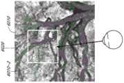
图1示出了通过AR装置的用户的增强现实(AR)的视图。Figure 1 shows an augmented reality (AR) view of a user through an AR device.
图2示出了用于为用户模拟三维影像的常规显示系统。Figure 2 shows a conventional display system for simulating three-dimensional imagery for a user.
图3A-3C示出了曲率半径和焦半径之间的关系。3A-3C illustrate the relationship between the radius of curvature and the focal radius.
图4A示出了人类视觉系统的调节-辐辏(accommodation-vergence)响应的表示。Figure 4A shows a representation of the accommodation-vergence response of the human visual system.
图4B示出了用户的一对眼睛的不同调节状态和辐辏状态的示例。FIG. 4B shows examples of different accommodation states and vergence states of a pair of eyes of a user.
图4C示出了用户通过显示系统观看内容的俯视图的表示的示例。4C shows an example of a representation of a top view of a user viewing content through a display system.
图4D示出了用户通过显示系统观看内容的俯视图的表示的另一示例。4D illustrates another example of a representation of a top view of a user viewing content through a display system.
图5示出了用于通过修改波前发散来模拟三维影像的方法的方面。5 illustrates aspects of a method for simulating three-dimensional imagery by modifying wavefront divergence.
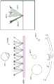
图6示出了用于向用户输出图像信息的波导堆叠的示例。Figure 6 shows an example of a waveguide stack for outputting image information to a user.
图7示出了由波导输出的出射束的示例。Figure 7 shows an example of the exit beam output by the waveguide.
图8示出了堆叠波导组件的示例,其中,每个深度平面包括使用多个不同分量颜色形成的图像。Figure 8 shows an example of a stacked waveguide assembly where each depth plane includes an image formed using multiple different component colors.
图9A示出了堆叠波导组的示例的剖面侧视图,每个堆叠波导包括耦入光学元件。9A shows a cross-sectional side view of an example of a stack of waveguides, each stacked waveguide including an in-coupling optical element.
图9B示出了图9A的多个堆叠波导的示例的透视图。9B shows a perspective view of an example of the multiple stacked waveguides of FIG. 9A.
图9C示出了图9A和9B的多个堆叠波导的示例的俯视平面视图。9C illustrates a top plan view of an example of the multiple stacked waveguides of FIGS. 9A and 9B.
图9D示出了可佩戴显示系统的示例。Figure 9D shows an example of a wearable display system.
图10A示出了用户通过显示系统观看内容的俯视图的表示的示例。10A shows an example of a representation of a top view of a user viewing content through a display system.
图10B示出了用户通过显示系统观看内容的俯视图的表示的另一示例。10B shows another example of a representation of a top view of a user viewing content through a display system.
图10C示出了用户通过显示系统观看内容的俯视图的表示的又一示例。Figure 1OC shows yet another example of a representation of a top view of a user viewing content through a display system.
图10D是示例显示系统的框图。10D is a block diagram of an example display system.
图11A1示出了基于三维注视点跟踪在不同分辨率调整区域中对分辨率调整的俯视图的表示的示例。FIG. 11A1 shows an example of a representation of a resolution-adjusted top view in different resolution-adjustment regions based on three-dimensional gaze tracking.
图11A2示出了随着分辨率调整区域的尺寸和数量变化而在不同时间的分辨率调整区域的俯视图的表示的示例。11A2 shows an example of a representation of a top view of resolution adjustment regions at different times as the size and number of resolution adjustment regions vary.
图11B示出了图11A1的分辨率调整区域的一部分的三维表示的示例。FIG. 11B shows an example of a three-dimensional representation of a portion of the resolution adjustment region of FIG. 11A1 .
图11C示出了分辨率调整区域的配置的另一示例。FIG. 11C shows another example of the configuration of the resolution adjustment area.
图11D示出了图11C的分辨率调整区域的三维表示的示例。Figure 11D shows an example of a three-dimensional representation of the resolution adjustment region of Figure 11C.
图11E示出了图11C的分辨率调整区域的三维表示的另一示例。Figure 11E shows another example of a three-dimensional representation of the resolution adjustment region of Figure 11C.
图12A至图12C示出了用于根据与三维注视点的接近度来调整内容的分辨率的过程的示例的图。12A-12C illustrate diagrams of an example of a process for adjusting the resolution of content according to proximity to a three-dimensional gaze point.
图13示出了用户观看与用户的视线对齐的多个虚拟对象的表示的示例。13 illustrates an example of a user viewing a representation of multiple virtual objects aligned with the user's line of sight.
图14是用于基于与用户视线的角接近度来调整虚拟内容的过程的示例的图。14 is a diagram of an example of a process for adjusting virtual content based on angular proximity to a user's line of sight.
图15示出了用户的眼睛的视网膜的表示的示例。Figure 15 shows an example of a representation of the retina of a user's eye.
图16图形化地示出了在图15的视网膜上的分辨率以及视杆和视锥密度的示例。FIG. 16 graphically shows an example of resolution and rod and cone densities on the retina of FIG. 15 .
图17图形化地示出了瞳孔尺寸和入射在用户的眼睛上的光量之间的关系的示例。FIG. 17 graphically shows an example of the relationship between pupil size and the amount of light incident on the user's eyes.
图18是用于基于入射在用户的眼睛上的光量来调整虚拟内容的过程的示例的图。FIG. 18 is a diagram of an example of a process for adjusting virtual content based on the amount of light incident on the user's eyes.
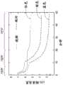
图19图形化地示出了随着入射在眼睛上的光量改变,用户的眼睛可检测到的分辨率改变的示例。Figure 19 graphically illustrates an example of a change in resolution detectable by a user's eye as the amount of light incident on the eye changes.
图20图形化地示出了在不同照射水平(level)下眼睛对不同颜色的光的敏感度差异的示例。Figure 20 graphically illustrates an example of differences in eye sensitivity to different colors of light at different illumination levels.
图21是用于调整使用多个分量颜色图像形成的虚拟内容的过程的示例的图,其中,基于分量颜色图像的颜色来进行分辨率调整。FIG. 21 is a diagram of an example of a process for adjusting virtual content formed using a plurality of component color images, in which resolution adjustment is performed based on colors of the component color images.
图22A-22C示出了随着入射到用户的眼睛上的光量减少来改变对比度敏感度的示例。22A-22C illustrate examples of changing contrast sensitivity as the amount of light incident on the user's eyes decreases.
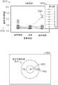
图23示出了用户眼睛的视神经和外围盲点的表示的示例。Figure 23 shows an example of a representation of the optic nerve and peripheral blind spot of a user's eye.
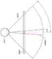
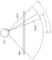
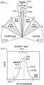
图24示出了人眼的示例性单眼视场。Figure 24 shows an exemplary monocular field of view of the human eye.
图25A示出了被配置为向用户提供虚拟内容的示例性可佩戴显示装置。25A illustrates an example wearable display device configured to provide virtual content to a user.
图25B是描绘增强现实系统的框图。25B is a block diagram depicting an augmented reality system.
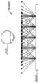
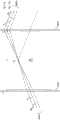
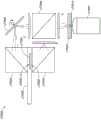
图25C示意性地示出了可用于向观看者呈现数字或虚拟图像的观看光学组件(VOA)中的光路。Figure 25C schematically illustrates the optical paths in a viewing optical assembly (VOA) that can be used to present a digital or virtual image to a viewer.
图26A-26D示出了AR系统中针对两个示例性眼睛取向中的每一个的待使用的示例性渲染视角和待产生的光场。Figures 26A-26D illustrate exemplary rendering perspectives to be used and light fields to be generated for each of two exemplary eye orientations in an AR system.
图26E-26F示意性地示出了可以呈现给用户的图像的示例性配置。26E-26F schematically illustrate exemplary configurations of images that may be presented to a user.
图26G-26H示意性地示出了可以呈现给用户的图像的示例性配置。26G-26H schematically illustrate exemplary configurations of images that may be presented to a user.
图27示出了图24所示的视场和能视域,该视场和能视域覆盖在如图25所示的可佩戴显示装置中的显示器之一上。FIG. 27 shows the field of view and field of view shown in FIG. 24 overlaid on one of the displays in the wearable display device shown in FIG. 25 .
图28A-28B示出了图26A-26D中描述的一些原理。Figures 28A-28B illustrate some of the principles described in Figures 26A-26D.
图28C-28D示出了可以呈现给用户的一些示例性图像。28C-28D illustrate some exemplary images that may be presented to a user.
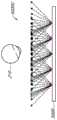
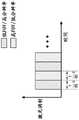
图28E示出了示例性高FOV低分辨率图像帧。Figure 28E shows an exemplary high FOV low resolution image frame.
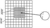
图28F示出了示例性低FOV高分辨率图像帧。Figure 28F shows an exemplary low FOV high resolution image frame.
图29A示出了显示系统的简化框图。Figure 29A shows a simplified block diagram of a display system.
图29B示意性地示出了增强现实(AR)系统的截面图。Figure 29B schematically shows a cross-sectional view of an augmented reality (AR) system.
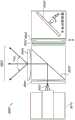
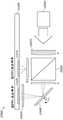
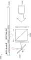
图30A-30B示意性地示出了用于将图像流投射到用户的眼睛的显示系统。30A-30B schematically illustrate a display system for projecting a stream of images to a user's eyes.
图30C示意性地示出了增强现实(AR)系统的截面图。Figure 30C schematically shows a cross-sectional view of an augmented reality (AR) system.
图30D示出了显示系统的简化框图。Figure 30D shows a simplified block diagram of a display system.
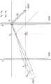
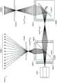
图31A示意性地示出了图30A-30B所图示的显示系统中的第一中继透镜组件的操作原理。Figure 31A schematically illustrates the principle of operation of the first relay lens assembly in the display system illustrated in Figures 30A-30B.
图31B示意性地示出了图30A-30B所图示的显示系统中的第二中继透镜组件的操作原理。Figure 31B schematically illustrates the principle of operation of the second relay lens assembly in the display system illustrated in Figures 30A-30B.
图31C-31D示意性地示出了显示系统。31C-31D schematically illustrate a display system.
图32A-32C示意性地示出了显示系统。32A-32C schematically illustrate a display system.
图33A-33B示意性地示出了显示系统。33A-33B schematically illustrate a display system.
图34A-34B示意性地示出了显示系统。34A-34B schematically illustrate a display system.
图35示意性地示出了显示系统。Figure 35 schematically shows a display system.
图36示意性地示出了增强现实近眼显示系统。FIG. 36 schematically shows an augmented reality near-eye display system.
图37A是双倍放大的无焦放大镜的示意图。Figure 37A is a schematic illustration of a double magnification afocal loupe.
图37B是双焦放大的无焦放大镜的示意图。37B is a schematic diagram of a bifocal magnifying afocal magnifier.
图38A-38B示意性地示出了可以呈现给用户的图像的示例性配置。38A-38B schematically illustrate exemplary configurations of images that may be presented to a user.
图39A-39B示出了可以呈现给用户的一些示例性图像。39A-39B illustrate some exemplary images that may be presented to a user.
图40A-40D示意性地示出了用于将图像流投射到用户的眼睛的显示系统。40A-40D schematically illustrate a display system for projecting a stream of images to a user's eye.
图41A-41D示意性地示出了用于将图像流投射到用户的眼睛的显示系统。41A-41D schematically illustrate a display system for projecting a stream of images to a user's eye.
图42示出了时分复用的高FOV低分辨率图像流和低FOV高分辨率图像流的示例性帧结构。FIG. 42 shows an exemplary frame structure of a time-division multiplexed high-FOV low-resolution image stream and a low-FOV high-resolution image stream.
图43示意性地示出了用于将图像流投射到用户的眼睛的显示系统。Figure 43 schematically illustrates a display system for projecting a stream of images to a user's eyes.
图44示意性地示出了用于将图像流投射到用户的眼睛的显示系统。Figure 44 schematically illustrates a display system for projecting a stream of images to a user's eyes.
图45示意性地示出了用于将图像流投射到用户的眼睛的显示系统。Figure 45 schematically illustrates a display system for projecting a stream of images to a user's eyes.
图46示意性地示出了用于将图像流投射到用户的眼睛的显示系统。Figure 46 schematically illustrates a display system for projecting a stream of images to a user's eyes.
图47示意性地示出了用于将图像流投射到用户的眼睛的显示系统。Figure 47 schematically shows a display system for projecting a stream of images to a user's eyes.
图48示意性地示出了用于将图像流投射到用户的眼睛的显示系统。Figure 48 schematically shows a display system for projecting a stream of images to a user's eyes.
图49示意性地示出了用于将图像流投射到用户的眼睛的显示系统。Figure 49 schematically illustrates a display system for projecting a stream of images to a user's eyes.
图50示意性地示出了根据一些实施例的用于将图像流投射到用户的眼睛的显示系统。Figure 50 schematically illustrates a display system for projecting a stream of images to a user's eyes, according to some embodiments.
图51示意性地示出了根据一些实施例的用于将图像流投射到用户的眼睛的显示系统。Figure 51 schematically illustrates a display system for projecting a stream of images to a user's eyes, according to some embodiments.
图52A-52B示意性地示出了根据一些实施例的用于将图像流投射到用户的眼睛的显示系统。52A-52B schematically illustrate a display system for projecting a stream of images to a user's eyes, according to some embodiments.
图53A-53B示意性地示出了根据一些实施例的用于将图像流投射到用户的眼睛的显示系统。53A-53B schematically illustrate a display system for projecting a stream of images to a user's eyes, according to some embodiments.
图54示出了用户的角视场的表示以及示例的分辨率分布。Figure 54 shows a representation of a user's angular field of view and an example resolution distribution.
图55A-55B示出了基于虚拟内容的类型来识别用于分辨率分布的滚降的示例方案。55A-55B illustrate example schemes for identifying roll-offs for resolution distributions based on the type of virtual content.
图55C-55D示出了针对不同类型的图像内容确定的平均滚降的曲线图。55C-55D show graphs of average roll-off determined for different types of image content.
图56示出了用于确定待在分辨率分布中使用的滚降的示例过程5600的流程图。56 shows a flowchart of an
图57示出了根据虚拟内容的类型来呈现虚拟内容的过程的示例流程图。57 shows an example flow diagram of a process for presenting virtual content according to the type of virtual content.
图58A示出了两个示例模糊区域。Figure 58A shows two example blur regions.
图58B示出了两个另外的示例模糊区域。Figure 58B shows two additional example blur regions.
图59示出了根据本文描述的技术的不同分辨率调整区域的示例。59 shows an example of different resolution adjustment regions according to the techniques described herein.
具体实施方式Detailed ways
渲染用于增强和虚拟显示系统的虚拟内容是计算密集的。除其他之外,计算强度可能不期望地使用大量的存储器,导致高等待时间,和/或可能需要使用可能具有高成本和/或高能耗的强大处理单元。Rendering virtual content for augmentation and virtual display systems is computationally intensive. Among other things, the computational intensity may undesirably use large amounts of memory, result in high latency, and/or may require the use of powerful processing units that may have high cost and/or high power consumption.
在一些实施例中,方法和系统通过降低位于远离用户眼睛的注视点的位置处的虚拟内容的分辨率来节省计算资源,诸如存储和处理时间。例如,系统可以在用户眼睛的注视点处或附近以相对高(例如,最高)的分辨率渲染虚拟内容,而针对远离该注视点的虚拟内容利用一个或多个较低分辨率。虚拟内容由显示系统呈现,该显示系统可以在多个不同的深度(例如,多个不同的深度平面,诸如两个或多个深度平面)上显示虚拟内容,并且分辨率的降低优选地沿着至少z轴发生,其中z轴是深度轴(对应于距用户的距离)。在一些实施例中,分辨率降低沿着z轴以及x和y轴中的一者或两者发生,其中x轴是横轴,而y轴是纵轴。In some embodiments, the methods and systems conserve computing resources, such as storage and processing time, by reducing the resolution of virtual content located at locations far from the gaze point of the user's eyes. For example, the system may render virtual content at a relatively high (eg, highest) resolution at or near the gaze point of the user's eyes, while utilizing one or more lower resolutions for virtual content further away from the gaze point. The virtual content is presented by a display system that can display the virtual content at multiple different depths (eg, multiple different depth planes, such as two or more depth planes), and the reduction in resolution is preferably along At least the z-axis occurs, where the z-axis is the depth axis (corresponding to distance from the user). In some embodiments, the resolution reduction occurs along the z axis and one or both of the x and y axes, where the x axis is the horizontal axis and the y axis is the vertical axis.
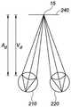
确定虚拟内容的适当分辨率可以包括确定用户的眼睛的在三维空间中的注视点。例如,注视点可以是用户的视场中的用户的眼睛注视的x、y、z坐标。显示系统可以被配置为呈现具有分辨率差异的虚拟对象,其中,分辨率随着虚拟对象与注视点的接近度的减小而减小;换句话说,分辨率随着距注视点距离的增加而降低。Determining the appropriate resolution for the virtual content may include determining the gaze point of the user's eyes in three-dimensional space. For example, the gaze point may be the x, y, z coordinates of the user's eye gaze in the user's field of view. The display system may be configured to present virtual objects with differences in resolution, wherein resolution decreases as the virtual object's proximity to the gaze point decreases; in other words, resolution increases with distance from the gaze point and decrease.
如本文中所讨论的,显示系统可在显示系统的显示平截头体内呈现虚拟对象,其中虚拟对象能够被呈现在不同的深度平面上。在一些实施例中,显示平截头体是由显示系统提供的视场,在该视场上,显示系统被配置为向显示系统的用户呈现虚拟内容。该显示系统可以是包括一个或多个波导的头戴式显示系统,该一个或多个波导可以呈现虚拟内容(例如,虚拟对象、图形、文本等),其中,该一个或多个波导被配置为输出具有对应于不同深度平面(例如,对应于距用户的特定距离)的不同波前发散和/或不同双目视差的光。将理解的是,每只眼睛可以具有相关联的一个或多个波导。使用不同的波前散和/或不同的双目视差,显示系统可以使第一虚拟对象看起来位于用户视场内的第一深度,同时使第二虚拟对象看起来位于用户视场内的第二深度。在一些实施例中,可以确定注视点的深度平面或到注视点的接近深度平面,并且可以基于那些深度平面到注视点所位于的深度平面的距离来降低其他深度平面上的内容的分辨率。将理解的是,在本文中对虚拟内容的深度(虚拟内容在z轴上距用户的距离)的提及指的是如旨在将被用户看到的虚拟内容的表观深度。在一些实施例中,虚拟对象的深度可以理解为是具有与虚拟对象的波前发散和/或双目视差相似的真实对象到用户的距离。As discussed herein, a display system can render virtual objects within a display frustum of the display system, where the virtual objects can be rendered on different depth planes. In some embodiments, the display frustum is a field of view provided by the display system over which the display system is configured to present virtual content to a user of the display system. The display system may be a head mounted display system including one or more waveguides that may present virtual content (eg, virtual objects, graphics, text, etc.), wherein the one or more waveguides are configured To output light with different wavefront divergences and/or different binocular disparities corresponding to different depth planes (eg, corresponding to specific distances from the user). It will be appreciated that each eye may have one or more waveguides associated. Using different wavefront dispersion and/or different binocular disparity, the display system can make the first virtual object appear to be located at a first depth within the user's field of view, while making the second virtual object appear to be located at a first depth within the user's field of view. Second depth. In some embodiments, the depth plane of the gaze point or a close depth plane to the gaze point may be determined, and the resolution of content on other depth planes may be reduced based on the distance of those depth planes to the depth plane on which the gaze point is located. It will be understood that references herein to the depth of the virtual content (the distance of the virtual content from the user on the z-axis) refer to the apparent depth of the virtual content as it is intended to be seen by the user. In some embodiments, the depth of the virtual object can be understood as the distance from the real object to the user that has wavefront divergence and/or binocular disparity similar to the virtual object.
将理解的是,可以通过各种措施来确定虚拟对象到注视点的接近度,各种措施的非限制性示例包括确定注视点和虚拟对象之间的距离;相对于注视点所占据的分辨率调整区域(在如下所述的将用户的视场划分为分辨率调整区域的实施例中),确定由虚拟对象所占据的分辨率调整区域;以及确定虚拟对象与用户的注视点的角接近度。也可以使用上述技术的组合来确定接近度。例如,第一区域(虚拟对象所位于的区域)与第二区域(注视点所位于的区域)的距离和/或角接近度可用于确定接近度。这些各种措施将在下面进一步讨论。It will be appreciated that the proximity of the virtual object to the gaze point may be determined by various measures, non-limiting examples of which include determining the distance between the gaze point and the virtual object; relative to the resolution occupied by the gaze point Adjusting the area (in embodiments in which the user's field of view is divided into resolution adjustment areas as described below), determining the resolution adjustment area occupied by the virtual object; and determining the angular proximity of the virtual object to the user's gaze point . Proximity can also be determined using a combination of the above techniques. For example, the distance and/or angular proximity of the first area (the area where the virtual object is located) and the second area (the area where the gaze point is located) can be used to determine proximity. These various measures are discussed further below.
在一些实施例中,确定注视点可以包括预测用户眼睛的注视点,并且将预测的注视点用作用于确定虚拟内容的分辨率的注视点。例如,在期望用户的眼睛注视在特定内容上的情况下,显示系统可以以相对高的分辨率渲染该内容。作为示例,将理解的是,人类视觉系统可能对场景中的突然变化(例如,突然的运动、亮度的变化等)敏感。在一些实施例中,显示系统可以确定将导致用户的眼睛注视在其上的虚拟内容的类型(例如,涉及场景中的运动,在该场景中,其他虚拟和真实对象静止),然后在期望用户的眼睛随后将聚焦在该虚拟内容上的情况下,以高分辨率呈现该虚拟内容。In some embodiments, determining the gaze point may include predicting the gaze point of the user's eyes, and using the predicted gaze point as the gaze point for determining the resolution of the virtual content. For example, where the user's eyes are expected to be fixed on certain content, the display system may render that content at a relatively high resolution. As an example, it will be appreciated that the human visual system may be sensitive to sudden changes in a scene (eg, sudden motion, changes in brightness, etc.). In some embodiments, the display system may determine the type of virtual content on which the user's eyes will be caused to fixate (eg, involving motion in a scene where other virtual and real objects are stationary), and then The virtual content is rendered in high resolution with the eyes of the user then focused on the virtual content.
如上所述,在一些实施例中,从所确定的注视点到虚拟对象的距离可以对应于三维延伸的距离。作为示例,第一虚拟对象的分辨率可以与第二虚拟对象类似地降低,其中,第一虚拟对象位于与所确定的注视点距用户相同深度(例如,在相同深度平面处),但从注视点水平或纵向定位的,而第二虚拟对象位于距所确定的注视点更远(例如,更远的平面)。因此,不同的分辨率可能与距注视点的不同距离相关联。As noted above, in some embodiments, the distance from the determined gaze point to the virtual object may correspond to a three-dimensionally extended distance. As an example, the resolution of the first virtual object may be reduced similarly to the second virtual object, wherein the first virtual object is located at the same depth (eg, at the same depth plane) from the user as the determined gaze point, but is located from the gaze point The point is positioned horizontally or vertically, while the second virtual object is positioned further (eg, a farther plane) from the determined gaze point. Therefore, different resolutions may be associated with different distances from the fixation point.
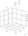
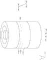
在一些实施例中,可以将用户周围的环境分成多个空间体积(volumes of space)(在本文中也称为分辨率调整区域),其中相同分辨率调整区域内的虚拟对象的分辨率相似。如本文所描述的,分辨率调整区域可具有任意的三维形状,例如立方体,或其他三维多边形形状,或弯曲的三维形状。在一些实施例中,所有分辨率调整区域具有相似的形状,例如长方体或球形。在一些其他实施例中,不同的分辨率调整区域可以具有不同的形状或尺寸(例如,体积的形状和/或尺寸可以随着距注视点的距离而改变)。In some embodiments, the environment around the user may be divided into volumes of space (also referred to herein as resolution adjustment areas), wherein virtual objects within the same resolution adjustment area are of similar resolution. As described herein, the resolution adjustment region may have any three-dimensional shape, such as a cube, or other three-dimensional polygonal shape, or a curved three-dimensional shape. In some embodiments, all resolution adjustment regions have similar shapes, such as cuboids or spheres. In some other embodiments, different resolution adjustment regions may have different shapes or sizes (eg, the shape and/or size of the volume may vary with distance from the gaze point).
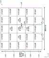
在一些实施例中,分辨率调整区域是用户视场的一部分。例如,用户的视场可以被分成形成分辨率调整区域的空间体积。在一些实施例中,每个深度平面可以细分为一个或多个连续的空间体积,即,一个或多个分辨率调整区域。在一些实施例中,每个分辨率调整区域可以包含距用户的特定深度范围(例如,深度平面值+/-a方差,其中方差的示例包括0.66dpt、0.50dpt、0.33dpt或0.25dpt),以及特定的横向距离和特定的垂直距离。位于与确定的注视点相同的分辨率调整区域内的虚拟对象可以以高(例如,全)分辨率呈现(例如渲染),而位于注视点的分辨率调整区域之外的体积中的虚拟对象可以根据该体积距注视点的空间体积的距离以更低的分辨率渲染。在一些实施例中,可以为每个分辨率调整区域分配特定的分辨率(例如,相对于全分辨率的特定分辨率的降低),并且可以以针对给定区域的相关联分辨率来渲染落入该给定区域内的虚拟内容。在一些实施例中,可以确定某一体积与注视点所占据的体积之间的距离,并且可以基于该距离来设置分辨率。In some embodiments, the resolution adjustment area is part of the user's field of view. For example, the user's field of view may be divided into spatial volumes that form resolution adjustment regions. In some embodiments, each depth plane may be subdivided into one or more contiguous spatial volumes, ie, one or more resolution adjustment regions. In some embodiments, each resolution adjustment region may contain a specific depth range from the user (eg, depth plane value +/- a variance, where examples of variance include 0.66dpt, 0.50dpt, 0.33dpt, or 0.25dpt), As well as a specific lateral distance and a specific vertical distance. Virtual objects located within the same resolution adjustment area as the determined foveation point may be rendered (eg, rendered) at high (eg, full) resolution, while virtual objects located in volumes outside the foveated point's resolution adjustment area may be rendered (eg, rendered) at high (eg, full) resolution Renders at a lower resolution based on the volume's distance from the foveated spatial volume. In some embodiments, each resolution adjustment region may be assigned a specific resolution (eg, a reduction of the specific resolution relative to full resolution), and the fall may be rendered at an associated resolution for a given region virtual content into the given area. In some embodiments, the distance between a volume and the volume occupied by the gaze point can be determined, and the resolution can be set based on this distance.
有利地,可以根据用户的所确定的注视点的置信度来修改用于划分用户视场的分辨率调整区域的数量和尺寸。例如,可以基于用户的视线接近三维空间中的精确点的置信度来增大或减小与每个空间体积相关联的尺寸。如果对注视点的置信度很高,则显示系统可以仅在紧凑的分辨率调整区域(包括注视点的紧凑的分辨率调整区域)内以相对高的分辨率呈现虚拟对象,同时降低其他虚拟对象的分辨率,并且因此节省了处理能力。然而,如果置信度低,则显示系统可以增加每个空间体积的尺寸(例如,减少体积的总数),使得每个空间体积在注视点的空间体积中包含更多数量的虚拟对象。将理解的是,可以在显示系统的生产期间固定体积的尺寸和形状,例如,基于用于确定注视点的系统中的预期公差,和/或可以根据用户的特征、用户的环境和/或改变用于确定注视点的系统的容差的软件改变来现场调整或设置。Advantageously, the number and size of resolution adjustment regions used to divide the user's field of view may be modified according to the user's confidence in the determined gaze point. For example, the size associated with each volume of space may be increased or decreased based on the confidence that the user's line of sight is approaching a precise point in three-dimensional space. If the confidence in the fixation point is high, the display system may render virtual objects at relatively high resolution only within a compact resolution adjustment region (comprising the compact resolution adjustment region of the fixation point), while reducing other virtual objects resolution, and thus save processing power. However, if the confidence is low, the display system may increase the size of each spatial volume (eg, reduce the total number of volumes) so that each spatial volume contains a greater number of virtual objects in the spatial volume of the fixation point. It will be appreciated that the size and shape of the volume may be fixed during production of the display system, eg, based on expected tolerances in the system used to determine the point of gaze, and/or may vary according to the user's characteristics, the user's environment and/or Software changes to the tolerance of the system used to determine the fixation point are adjusted or set on the spot.
将理解的是,用户对分辨率的敏感度可能会随着距注视点的距离而降低。因此,通过确保在注视点处呈现全分辨率的内容,并允许在注视点所在的位置留出误差界限,可以减少或消除分辨率降低的感觉,从而提供高分辨率显示器的感觉,而无需利用呈现这种高分辨率显示器内容通常所需要的计算资源。It will be appreciated that the user's sensitivity to resolution may decrease with distance from the point of gaze. Thus, by ensuring that full resolution content is rendered at the point of gaze, and allowing margins of error where the point of gaze is located, the perception of reduced resolution can be reduced or eliminated, providing the perception of a high-resolution display without utilizing The computing resources typically required to render such high-resolution display content.
在一些实施例中,可以基于虚拟对象与用户的视线的角接近度来确定虚拟对象与注视点的接近度,并且当角接近度降低时,虚拟对象的分辨率可以降低。在一些实施例中,这可能导致以相似的分辨率呈现位于距用户不同深度的虚拟对象。例如,在与用户的所确定的注视点相对应的位置处的第一虚拟对象可以位于第二虚拟对象的前面(例如,在深度上更靠近用户)。由于第二虚拟对象将沿着用户的视线,并因此类似地落在用户的中央凹上,在该中央凹上,用户的眼睛对分辨率的改变最为敏感,可以可选地以与第一虚拟对象相似(例如相同)的分辨率呈现第二虚拟对象。可选地,可以减小第二虚拟对象的分辨率,并且可以通过模糊处理来进一步调整第二虚拟对象(例如,高斯模糊内核可以与第二虚拟对象卷积),这可以表示第二虚拟对象距用户更远(例如,位于更远的平面上)。In some embodiments, the proximity of the virtual object to the gaze point may be determined based on the angular proximity of the virtual object to the user's line of sight, and as the angular proximity decreases, the resolution of the virtual object may decrease. In some embodiments, this may result in rendering virtual objects located at different depths from the user at similar resolutions. For example, a first virtual object at a location corresponding to the user's determined gaze point may be located in front of a second virtual object (eg, closer in depth to the user). Since the second virtual object will follow the user's line of sight, and thus similarly fall on the user's fovea, where the user's eyes are most sensitive to changes in resolution, it can optionally be compared to the first virtual object. The second virtual object is rendered at a resolution where the objects are similar (eg, the same). Optionally, the resolution of the second virtual object may be reduced, and the second virtual object may be further adjusted by blurring (eg, a Gaussian blur kernel may be convolved with the second virtual object), which may represent the second virtual object Farther from the user (eg, on a farther plane).
分辨率的降低可以基于显示系统如何呈现虚拟内容而变化。在一些实施例中,本文中称为可变焦显示系统的第一示例显示系统可以在不同深度平面上呈现虚拟内容,其中,所有内容(例如,虚拟对象)一次(例如,针对呈现给用户的每一帧)呈现在相同深度平面上(例如,经由相同的波导)。即,可变焦显示系统可以一次利用单个深度平面(例如,基于用户的注视点从多个深度平面中选择的,或者基于特定呈现的虚拟对象的深度选择的)来呈现内容,并且可以在后续帧中改变深度平面(例如,选择不同的深度平面)。在一些其他实施例中,本文中称为多焦显示系统的第二示例显示系统可以在不同深度平面上呈现虚拟内容,其中,同时在多个深度平面上显示内容。如本文将进一步描述的,可变焦显示系统可以可选地利用单帧缓冲器,并且相对于以上关于模糊第二虚拟对象的示例,可以在将第二虚拟对象从单帧缓冲器呈现给用户之前对第二虚拟对象进行模糊。相反,多焦显示系统可以可选地以降低的分辨率在距第一虚拟对象更远的深度(例如,在另一深度平面上)呈现第二虚拟对象,并且第二虚拟对象可以对用户看起来是模糊的(例如,第二虚拟对象将基于用户眼睛的自然物理机制而被模糊,无需进一步处理)。The reduction in resolution may vary based on how the display system renders the virtual content. In some embodiments, a first example display system, referred to herein as a variable-focus display system, can present virtual content at different depth planes, wherein all content (eg, virtual objects) is presented at once (eg, for each presentation presented to the user). one frame) are presented on the same depth plane (eg, via the same waveguide). That is, the zoom display system can render content using a single depth plane at a time (eg, selected from multiple depth planes based on the user's gaze point, or selected based on the depth of a particular rendered virtual object), and can display content in subsequent frames to change the depth plane (for example, select a different depth plane). In some other embodiments, a second example display system, referred to herein as a multifocal display system, can present virtual content on different depth planes, wherein the content is displayed on multiple depth planes simultaneously. As will be described further herein, the zoom display system may optionally utilize a single frame buffer, and relative to the above example of blurring the second virtual object, may be performed prior to presenting the second virtual object from the single frame buffer to the user Blur the second virtual object. Conversely, the multifocal display system may optionally present a second virtual object at a reduced resolution at a further depth (eg, in another depth plane) from the first virtual object, and the second virtual object may be viewed by the user is blurred (eg, the second virtual object will be blurred based on the natural physics of the user's eyes without further processing).
如本文所公开的,显示系统可以在所确定的注视点处或附近以相对高(例如,全)分辨率呈现虚拟对象,并且可以在远离注视点处以降低的分辨率呈现虚拟对象。优选地,相对高的分辨率是用于在用户视场中呈现虚拟对象的最高分辨率。相对高的分辨率可以是显示系统的最大分辨率、用户可选择的分辨率、基于呈现虚拟对象的特定计算硬件的分辨率等。As disclosed herein, a display system may render virtual objects at relatively high (eg, full) resolution at or near the determined gaze point, and may render virtual objects at reduced resolution away from the gaze point. Preferably, the relatively high resolution is the highest resolution used to render virtual objects in the user's field of view. The relatively high resolution may be the maximum resolution of the display system, a user-selectable resolution, a resolution based on the particular computing hardware that renders the virtual object, or the like.
将理解的是,调整虚拟对象的分辨率可以包括改变虚拟对象的呈现质量的对虚拟对象的任何修改。这样的修改可以包括以下一项或多项:调整虚拟对象的多边形计数、调整用于生成虚拟对象的图元(例如,调整图元的形状,例如将图元从三角形网格调整为四边形网格等)、调整对虚拟对象执行的操作(例如,着色器操作)、调整纹理信息、调整颜色分辨率或深度、调整渲染周期数或帧率等,包括调整图形处理单元(GPU)的图形管线内的一个或多个点的质量。It will be appreciated that adjusting the resolution of the virtual object may include any modification to the virtual object that alters the rendering quality of the virtual object. Such modifications may include one or more of the following: adjusting the polygon count of the virtual object, adjusting the primitives used to generate the virtual object (eg, adjusting the shape of the primitives, such as resizing the primitives from a triangular mesh to a quadrilateral mesh) etc.), adjusting operations performed on virtual objects (e.g., shader operations), adjusting texture information, adjusting color resolution or depth, adjusting the number of rendering cycles or frame rate, etc., including adjustments within the graphics pipeline of the graphics processing unit (GPU) the mass of one or more points.
在一些实施例中,在x轴和y轴上,远离注视点的虚拟内容的分辨率改变通常可以跟踪用户眼睛的视网膜中感光体分布的改变。例如,将理解的是,可以将世界的视图和虚拟内容的视图成像在视网膜上,使得可以将视网膜的不同部分映射到用户视场的不同部分。有利的是,在整个用户视场内的虚拟内容的分辨率通常可以跟踪整个视网膜上相应感光体(视杆或视锥)的密度。在一些实施例中,远离注视点的分辨率降低通常可以跟踪整个视网膜的视锥密度的降低。在一些其他实施例中,远离注视点的分辨率降低通常可以跟踪整个视网膜的视杆的密度的降低。在一些实施例中,远离注视点的分辨率降低的趋势可以在整个视网膜内的视杆和/或视锥的密度降低的趋势的±50%、±30%、±20%或±10%之内。In some embodiments, changes in resolution of virtual content away from the point of gaze can generally track changes in the distribution of photoreceptors in the retina of the user's eye on the x- and y-axes. For example, it will be appreciated that the view of the world and the view of the virtual content can be imaged on the retina such that different parts of the retina can be mapped to different parts of the user's field of view. Advantageously, the resolution of virtual content throughout the user's field of view can typically track the density of corresponding photoreceptors (rods or cones) across the retina. In some embodiments, the reduction in resolution away from the fixation point can generally track the reduction in cone density across the retina. In some other embodiments, the reduction in resolution away from the fixation point can generally track the reduction in the density of rods across the retina. In some embodiments, the trend of decreased resolution away from the fixation point may be within ±50%, ±30%, ±20%, or ±10% of the trend of decreased density of rods and/or cones throughout the retina Inside.
视杆和视锥在不同的入射光水平下活跃。例如,视锥在相对明亮的条件下活跃,而视杆在相对弱的光条件下活跃。因此,在分辨率的降低通常跟踪整个视网膜上的视杆或视锥的密度的一些实施例中,显示系统可以被配置为确定入射在视网膜上的光量。基于此光量,可以对分辨率进行适当的调整。例如,分辨率的降低通常可以在弱光条件下跟踪整个视网膜的视杆密度的改变,而分辨率的降低通常可以在明亮的条件下跟踪视锥密度的改变。因此,在一些实施例中,显示系统可以被配置为基于入射在视网膜上的光量来改变图像分辨率降低的轮廓。Rods and cones are active at different incident light levels. For example, cones are active in relatively bright conditions, while rods are active in relatively low light conditions. Thus, in some embodiments where the reduction in resolution typically tracks the density of rods or cones across the retina, the display system may be configured to determine the amount of light incident on the retina. Based on this amount of light, the resolution can be adjusted appropriately. For example, a reduction in resolution can often track changes in rod density across the retina in low-light conditions, while a reduction in resolution can often track changes in cone density in bright conditions. Accordingly, in some embodiments, the display system may be configured to vary the profile of the image resolution reduction based on the amount of light incident on the retina.
将理解的是,人眼分辨细微细节的能力可能与视网膜中视杆或视锥的密度不直接成比例。在一些实施例中,整个用户视场的虚拟内容的分辨率的改变通常跟踪眼睛分辨细微细节的能力的改变。如以上注意到的,虚拟内容的分辨率改变的进程可以随着到达视网膜的光量而变化。It will be appreciated that the ability of the human eye to resolve fine details may not be directly proportional to the density of rods or cones in the retina. In some embodiments, changes in the resolution of virtual content across the user's field of view typically track changes in the eye's ability to resolve fine details. As noted above, the course of the resolution change of the virtual content may vary with the amount of light reaching the retina.
在一些实施例中,可以通过检测入射在传感器上的环境光量来确定到达视网膜的光量,该传感器安装在显示装置上。在一些实施例中,确定到达视网膜的光量还可以包括确定由显示装置向用户输出的光量。在其他实施例中,可以通过对用户的眼睛成像以确定瞳孔尺寸来确定到达视网膜的光量。因为瞳孔尺寸与到达视网膜的光量有关,所以确定瞳孔尺寸允许推断到达视网膜的光量。In some embodiments, the amount of light reaching the retina may be determined by detecting the amount of ambient light incident on a sensor mounted on the display device. In some embodiments, determining the amount of light reaching the retina may also include determining the amount of light output by the display device to the user. In other embodiments, the amount of light reaching the retina may be determined by imaging the user's eye to determine pupil size. Because pupil size is related to the amount of light reaching the retina, determining pupil size allows inferring the amount of light reaching the retina.
将理解的是,全色虚拟内容可以由多个分量颜色图像形成,这些分量颜色图像总体上提供对全色的感知。人眼对光的不同波长或颜色可能具有不同的敏感度。在一些实施例中,除了基于与注视点的接近度而改变之外,虚拟内容的分辨率的改变可以基于由显示系统呈现的分量颜色图像的颜色而变化。例如,如果分量颜色图像包括红色,绿色和蓝色图像,则绿色分量颜色图像可以具有比红色分量颜色图像更高的分辨率,而红色分量颜色图像可以具有比蓝色分量颜色图像更高的分辨率。在一些实施例中,为了解决眼睛在不同的入射光水平下对不同颜色的敏感度的变化,可以确定到达视网膜的光量,并且针对给定分量颜色图像的分辨率调整也可以基于到达视网膜的光量的确定而变化。It will be appreciated that panchromatic virtual content may be formed from multiple component color images that collectively provide the perception of panchromatic. The human eye may have different sensitivity to different wavelengths or colors of light. In some embodiments, the change in resolution of the virtual content may change based on the color of the component color image presented by the display system, in addition to the change based on the proximity to the gaze point. For example, if the component color image includes red, green, and blue images, the green component color image may have a higher resolution than the red component color image, and the red component color image may have a higher resolution than the blue component color image Rate. In some embodiments, to account for variations in the eye's sensitivity to different colors at different incident light levels, the amount of light reaching the retina may be determined, and the resolution adjustment for a given component color image may also be based on the amount of light reaching the retina changes with the determination.
将理解的是,眼睛的对比度敏感度也可以基于入射在视网膜上的光量而变化。在一些实施例中,虚拟内容中对比度的分级尺寸或总数可以基于到达视网膜的光量而变化。在一些实施例中,形成虚拟内容的图像的对比率可以基于入射在视网膜上的光量而变化,其中,对比率随着光量的减少而减小。It will be appreciated that the contrast sensitivity of the eye may also vary based on the amount of light incident on the retina. In some embodiments, the scaled size or total amount of contrast in the virtual content may vary based on the amount of light reaching the retina. In some embodiments, the contrast ratio of the image forming the virtual content may vary based on the amount of light incident on the retina, wherein the contrast ratio decreases as the amount of light decreases.
在一些实施例中,用户视场的某些部分可能没有提供任何虚拟内容。例如,显示系统可以被配置为不在由视神经引起的盲点和/或给定眼睛的外围盲点中提供虚拟内容。In some embodiments, certain portions of the user's field of view may not provide any virtual content. For example, the display system may be configured not to provide virtual content in a blind spot caused by the optic nerve and/or a peripheral blind spot of a given eye.
如本文中所讨论的,显示系统以被配置为在用户的视场的一部分中显示高分辨率内容,而在用户的视场的另一部分中显示较低分辨率的内容。将理解的是,高分辨率内容可以具有比较低分辨率内容更高的像素密度。在一些环境中,显示系统可以被配置为通过有效地叠加高分辨率和低分辨率图像来提供这种高分辨率和低分辨率内容。例如,系统可以显示跨整个视场的低分辨率图像,并且然后显示整个视场的一小部分的高分辨率图像,其中,高分辨率图像位于与低分辨率图像的对应部分的相同的位置。高分辨率图像和低分辨率图像可以通过不同的光学器件引导,这些光学器件以适当的角度输出光以确定这些图像占据了多大视场。As discussed herein, the display system is configured to display high resolution content in one portion of the user's field of view and lower resolution content in another portion of the user's field of view. It will be appreciated that high resolution content may have a higher pixel density than lower resolution content. In some environments, the display system may be configured to provide such high-resolution and low-resolution content by effectively overlaying high-resolution and low-resolution images. For example, the system may display a low-resolution image across the entire field of view, and then display a high-resolution image of a small portion of the entire field of view, where the high-resolution image is located at the same location as the corresponding portion of the low-resolution image . High-resolution and low-resolution images can be directed through different optics that output light at the appropriate angle to determine how large a field of view these images occupy.
在一些实施例中,可以使用单个空间光调制器(SLM)用图像信息对光进行编码,并且可以使用分束器或光学开关将来自SLM的单个光流分成两个流,一个流传播通过用于低分辨率图像的光学器件,而第二流传播通过用于高分辨率图像的光学器件。在一些其他实施例中,编码有图像信息的光的偏振可以被选择性地切换并且穿过有效地为不同偏振的光提供不同的角放大率的光学器件,从而提供高分辨率图像和低分辨率图像。In some embodiments, a single spatial light modulator (SLM) can be used to encode light with image information, and a beam splitter or optical switch can be used to split a single optical flow from the SLM into two streams, one propagating through the optics for low-resolution images, while the second stream propagates through optics for high-resolution images. In some other embodiments, the polarization of the light encoded with image information can be selectively switched and passed through optics that effectively provide different angular magnifications for light of different polarizations, thereby providing high resolution images and low resolution rate image.
有利地,本文公开的各种实施例降低了用于在显示系统上提供内容的处理能力的要求。由于处理能力的较大份额可以分配给靠近用户的三维注视点的虚拟对象,而用于更远处的虚拟对象的处理能力可以减少,因此可以减少用于显示系统总体所需处理能力,从而减少了以下中的一项或多项:处理组件的尺寸、处理组件产生的热量和显示系统的能量需求(例如,显示系统可以可选地由电池供电、需要较低容量的电池和/或用给定电池操作更长的持续时间)。因此,本文描述的实施例解决了由增强或虚拟现实显示系统引起的技术问题。另外,所描述的技术操纵图形内容,使得在呈现给用户时,图形内容根本上不同地呈现(例如,分辨率被修改),而图形内容在用户看来可能是相同的。因此,当用户环顾周围环境时,显示系统变换图形内容,同时保留视觉保真度并节省处理能力。Advantageously, the various embodiments disclosed herein reduce the processing power requirements for providing content on a display system. Since a larger share of processing power can be allocated to virtual objects close to the user's 3D fixation point, and processing power for virtual objects that are further away can be reduced, the processing power required for the display system as a whole can be reduced, thereby reducing One or more of the following: the size of the processing components, the heat generated by the processing components, and the energy requirements of the display system (e.g., the display system may optionally be battery powered, require a lower capacity battery, and/or use longer duration of battery operation). Accordingly, the embodiments described herein address technical problems caused by augmented or virtual reality display systems. Additionally, the described techniques manipulate graphical content such that when presented to a user, the graphical content is presented fundamentally differently (eg, resolution is modified), whereas the graphical content may appear to the user to be the same. Thus, as the user looks around the surroundings, the display system transforms the graphical content while preserving visual fidelity and conserving processing power.
将理解的是,显示系统可以是增强现实显示系统或虚拟现实显示系统的一部分。作为一个示例,显示系统的显示器可以是透射的,并且可以允许用户查看真实世界,同时以图像、视频、交互等形式向用户提供虚拟内容。作为另一示例,显示系统可以阻挡用户对现实世界的观看,并且可以向用户呈现虚拟现实图像、视频、交互等。It will be appreciated that the display system may be part of an augmented reality display system or a virtual reality display system. As one example, the display of the display system may be transmissive and may allow a user to view the real world while providing virtual content to the user in the form of images, videos, interactions, and the like. As another example, a display system may block a user's viewing of the real world, and may present virtual reality images, videos, interactions, etc. to the user.
现在将参考附图,在所有附图中,相同的参考标号表示相同的部件。Reference will now be made to the drawings, wherein like reference numerals refer to like parts throughout.
图2示出了用于为用户模拟三维影像的常规显示系统。将理解到,用户的眼睛是间隔开的,并且当观看空间中的真实对象时,每只眼睛将具有略微不同的对象视图,并且可以在每只眼睛的视网膜上的不同位置处形成对象的图像。这可以被称为双目视差,并且可以由人类视觉系统利用以提供深度感知。常规的显示系统通过呈现具有相同虚拟对象的略微不同的视图(每只眼睛210、220一个)的两个不同图像190、200来模拟双目视差,该不同的视图对应于每只眼睛将看到的虚拟对象的视图,该虚拟对象是位于期望的深度处的真实对象的虚拟对象。这些图像提供双目提示,用户的视觉系统可以解释该双目提示以得到深度感知。Figure 2 shows a conventional display system for simulating three-dimensional imagery for a user. It will be appreciated that the user's eyes are spaced apart and when viewing a real object in space, each eye will have a slightly different view of the object, and images of the object may be formed at different locations on the retina of each eye . This can be referred to as binocular disparity, and can be exploited by the human visual system to provide depth perception. Conventional display systems simulate binocular disparity by presenting two
继续参考图2,图像190、200与眼睛210、220在z轴上隔开距离230。z轴平行于观看者的光轴,其中他们的眼睛注视在观看者正前方的光学无限远处的对象上。图像190、200是平坦的并且在距眼睛210、220的固定距离处。基于分别呈现给眼睛210、220的图像中的虚拟对象的略微不同的视图,眼睛可以自然旋转,使得对象的图像落在每只眼睛的视网膜上的相应点上,以维持单个双目视觉。该旋转可以使得每只眼睛210、220的视线会聚到空间中的点上,其中,虚拟对象被感知为存在于该点处。结果,提供三维影像通常涉及提供双目提示,该双目提示可以操纵用户眼睛210、220的辐辏,并且人类视觉系统解释该双目提示以提供深度感知。With continued reference to Figure 2, the
然而,产生真实且舒适的深度感知具有挑战性。将理解到,来自距眼睛不同距离处的对象的光具有不同发散量的波前。图3A-3C示出了距离与光线的发散之间的关系。对象与眼睛210之间的距离以减小的距离的次序由R1、R2和R3表示。如在图3A-3C中所示,随着到对象的距离减小,光线变得更发散。相反地,随着距离增加,光线变得更准直。换句话说,可以说由点(对象或者对象的一部分)产生的光场具有球面波前曲率,该球面波前曲率是该点距用户的眼睛多远的函数。曲率随着对象与眼睛210之间的距离的减小而增加。虽然在图3A-3C和本文中的其他附图中为了说明清晰起见,仅示出单只眼睛210,关于眼睛210的讨论可以适用于观看者的两只眼睛210和220。However, generating realistic and comfortable depth perception is challenging. It will be appreciated that light from objects at different distances from the eye has different diverging wavefronts. 3A-3C illustrate the relationship between distance and divergence of rays. The distances between the subject and the
继续参考图3A-3C,来自观看者的眼睛所注视的对象的光可以具有不同程度的波前发散。由于波前发散的量不同,光可以通过眼睛的晶状体而被不同地聚焦,这进而可能需要晶状体呈现不同的形状以在眼睛的视网膜上形成聚焦的图像。在视网膜上没有形成聚焦的图像的情况下,所产生的视网膜模糊充当对调节的提示,该对调节的提示引起眼睛的晶状体形状的改变,直到在视网膜上形成聚焦的图像。例如,对调节的提示可以触发眼睛晶状体周围的睫状肌松弛或收缩,从而调节施加到保持晶状体的悬韧带的力,由此引起眼睛晶状体的形状改变,直到注视的对象的视网膜模糊消除或最小化,从而在眼睛的视网膜(例如,中央凹)上形成注视对象的聚焦的图像。眼睛的晶状体改变形状的过程可以称为调节,并且在眼睛的视网膜(例如,中央凹)上形成注视对象的聚焦的图像所需的眼睛的晶状体的形状可以称为调节状态。With continued reference to Figures 3A-3C, light from an object upon which the viewer's eyes are fixed may have varying degrees of wavefront divergence. Due to the different amounts of wavefront divergence, light can be focused differently through the lens of the eye, which in turn may require the lens to assume a different shape to form a focused image on the retina of the eye. In the absence of a focused image forming on the retina, the resulting retinal blur acts as a cue to accommodation that causes changes in the shape of the eye's lens until a focused image is formed on the retina. For example, a cue to accommodate can trigger relaxation or contraction of the ciliary muscles surrounding the eye's lens, thereby adjusting the force applied to the suspensory ligament that holds the lens, thereby causing the eye's lens to change in shape until retinal blurring of the staring object is eliminated or minimized ization, thereby forming a focused image of the gazing object on the retina of the eye (eg, the fovea). The process by which the eye's lens changes shape may be referred to as accommodation, and the shape of the eye's lens required to form a focused image of a gazing object on the eye's retina (eg, the fovea) may be referred to as the accommodation state.
现在参考图4A,示出了人类视觉系统的调节-辐辏响应的表示。眼睛运动以注视对象引起眼睛接收来自对象的光,其中光在眼睛的视网膜中的每一个上形成图像。在视网膜上形成的图像中视网膜模糊的存在可以提供对调节的提示,并且图像在视网膜上的相对位置可以提供对辐辏的提示。对调节的提示引起调节发生,这导致眼睛的晶状体各自呈现特定的调节状态,该特定的调节状态在眼睛的视网膜(例如,中央凹)上形成对象的聚焦的图像。另一方面,对辐辏的提示引起辐辏运动(眼睛的转动)发生,使得在每只眼睛的每个视网膜上形成的图像处于维持单个双目视觉的相应视网膜点处。在这些位置,可以说眼睛已呈现特定的辐辏状态。继续参考图4A,调节可以被理解为眼睛实现特定调节状态的过程,并且辐辏可以被理解为眼睛实现特定辐辏状态的过程。如图4A中所示,如果用户注视另一个对象,则眼睛的调节和辐辏状态可以改变。例如,如果用户注视在z轴上的不同深度处的新对象,则调节状态可以改变。Referring now to FIG. 4A, a representation of the accommodation-vergence response of the human visual system is shown. Movement of the eye to gaze at an object causes the eye to receive light from the object, where the light forms an image on each of the retinas of the eye. The presence of retinal blur in images formed on the retina may provide cues for accommodation, and the relative position of the images on the retina may provide cues for convergence. A cue to accommodation causes accommodation to occur, which causes the lenses of the eye to each assume a specific accommodation state that forms a focused image of the subject on the eye's retina (eg, the fovea). On the other hand, cues to vergence cause vergence motion (rotation of the eye) to occur such that the image formed on each retina of each eye is at the corresponding retinal point that maintains a single binocular vision. In these positions, the eye can be said to have assumed a specific vergence state. With continued reference to Figure 4A, accommodation can be understood as the process by which the eye achieves a particular state of accommodation, and vergence can be understood as the process by which the eye achieves a particular state of convergence. As shown in Figure 4A, if the user is gazing at another object, the accommodation and vergence states of the eyes may change. For example, if the user gazes at a new object at a different depth on the z-axis, the accommodation state may change.
不受理论的限制,据信,由于辐辏和调节的组合,对象的观看者可以将对象感知为“三维的”。如上所述,两只眼睛相对于彼此的辐辏运动(例如,眼睛的转动使得瞳孔向着彼此或远离彼此运动以会聚眼睛的视线来注视对象)与眼睛的晶状体的调节紧密相关。在正常情况下,改变眼睛的晶状体的形状以将聚焦从一个对象改变到不同距离处的另一对象,将会在被称为“调节-辐辏反射”的关系下自动引起到相同距离的辐辏的匹配改变。同样,在正常情况下,辐辏的改变将触发晶状体形状的匹配改变。Without being bound by theory, it is believed that a viewer of an object may perceive the object as "three-dimensional" due to a combination of vergence and accommodation. As discussed above, the vergence movement of the two eyes relative to each other (eg, the rotation of the eyes to move the pupils toward or away from each other to converge the eyes of the eyes to fixate on objects) is closely related to the accommodation of the lenses of the eyes. Under normal circumstances, changing the shape of the eye's lens to change focus from one object to another at a different distance will automatically induce a vergence to the same distance in a relationship known as the "accommodation-vergence reflex" match changes. Also, under normal conditions, a change in vergence will trigger a matching change in lens shape.
现在参考图4B,示出了眼睛的不同调节和辐辏状态的示例。眼睛对222a注视在光学无穷远处的对象上,而眼睛对222b注视在小于光学无限远处的对象221上。值得注意的是,每对眼睛的辐辏状态不同,其中眼睛对222a指向正前方,而眼睛对222会聚在对象221上。形成每个眼睛对222a和222b的眼睛的调节状态是也不同,如由晶状体210a、220a的不同形状所表示的。Referring now to Figure 4B, examples of different accommodation and vergence states of the eye are shown.
不希望的是,常规“3-D”显示系统的许多用户发现由于这些显示器中的调节和辐辏状态之间的不匹配这些常规系统不舒服或者根本不会感知到深度感。如上所述,许多立体或“3-D”显示系统通过向每只眼睛提供略微不同的图像来显示场景。这样的系统对于许多观看者来说不舒服,因为除了其他事项之外它们仅仅提供场景的不同呈现并引起眼睛的辐辏状态的改变,但是没有那些眼睛的调节状态的相应改变。然而,图像由距眼睛固定距离处的显示器示出,使得眼睛在单个调节状态下观看所有图像信息。这种布置通过引起辐辏状态的改变而没有调节状态的匹配改变而违背“调节-辐辏反射”。这种不匹配被认为会引起观看者的不适。提供调节和辐辏之间的更好匹配的显示系统可以形成更真实和舒适的三维影像模拟。Undesirably, many users of conventional "3-D" display systems find these conventional systems uncomfortable or do not perceive depth at all due to the mismatch between accommodation and vergence states in these displays. As mentioned above, many stereoscopic or "3-D" display systems display scenes by presenting slightly different images to each eye. Such systems are uncomfortable for many viewers because, among other things, they merely provide a different presentation of the scene and cause changes in the vergence states of the eyes, but without a corresponding change in the accommodation states of those eyes. However, the image is shown by the display at a fixed distance from the eye so that the eye sees all image information in a single accommodation state. This arrangement violates the "accommodation-vergence reflex" by causing a change in vergence state without a matching change in accommodation state. This mismatch is thought to cause discomfort to the viewer. A display system that provides a better match between accommodation and vergence can result in a more realistic and comfortable three-dimensional image simulation.
不受理论限制,据信,人眼通常可解释有限数量的深度平面以提供深度感知。因此,通过向眼睛提供与这些有限数量的深度平面中的每一个相对应的图像的不同呈现,可实现高度可信的感知深度的模拟。在一些实施例中,不同的呈现可提供对辐辏的提示和对调节的匹配提示,从而提供生理上正确的调节-辐辏匹配。Without being bound by theory, it is believed that the human eye can generally interpret a limited number of depth planes to provide depth perception. Thus, by providing the eye with different representations of images corresponding to each of these limited number of depth planes, a highly confident simulation of perceived depth can be achieved. In some embodiments, different presentations may provide cues for vergence and matching cues for accommodation, thereby providing a physiologically correct accommodation-vergence match.
继续参考图4B,示出了对应于在空间中距眼睛210、220的不同距离的两个深度平面240。对于给定的深度平面240,可以通过为每只眼睛210、220显示适当不同透视的图像来提供辐辏提示。此外,对于给定的深度平面240,形成提供给每只眼睛210、220的图像的光可以具有与由该深度平面240的距离处的点产生的光场对应的波前发散。With continued reference to Figure 4B, two
在所图示的实施例中,包含点221的深度平面240沿z轴的距离是1m。如本文所使用的,可以测量沿z轴的距离或深度,其中,零点位于用户眼睛的出射光瞳处。因此,在那些眼睛的光轴上,位于1m深度处的深度平面240与距用户眼睛的出射光瞳1m远的距离对应。作为近似,沿着z轴的深度或距离可以从用户眼睛前方的显示器(例如,从波导的表面)测量,加上装置和用户眼睛的出射光瞳之间的距离的值,其中眼睛指向光学无限远。该值可以被称为适眼距(eye relief)并且对应于用户眼睛的出射光瞳与用户在眼睛前方佩戴的显示器之间的距离。在实践中,适眼距的值可以是通常对于所有观看者使用的标准化值。例如,可以假设适眼距是20mm,以及深度为1m的深度平面可以在显示器前方980mm的距离处。In the illustrated embodiment, the distance along the z-axis of
现在参考图4C和4D,分别示出了匹配的调节-辐辏距离和不匹配的调节-辐辏距离的示例。如图4C所图示的,显示系统可以向每只眼睛210、220提供虚拟对象的图像。图像可以使眼睛210、220呈现眼睛会聚在深度平面240上的点15上的辐辏状态。此外,图像可以由具有与该深度平面240处的真实对象相对应的波前曲率的光形成。结果,眼睛210、220呈现图像在那些眼睛的视网膜上合焦的调节状态。因此,用户可以感知到虚拟对象在深度平面240上的点15处。Referring now to Figures 4C and 4D, examples of matched accommodation-convergence distances and unmatched accommodation-convergence distances are shown, respectively. As illustrated in Figure 4C, the display system may provide each
将理解到,眼睛210、220的调节和辐辏状态中的每一者与z轴上的特定距离相关联。例如,在距眼睛210、220特定距离处的对象使那些眼睛基于对象的距离呈现特定的调节状态。与特定调节状态相关联的距离可以被称为调节距离Ad。类似地,存在与在特定辐辏状态下的眼睛或相对于彼此的位置相关联的特定的辐辏距离Vd。在调节距离和辐辏距离匹配的情况下,可以说调节和辐辏之间的关系在生理学上是正确的。这被认为是对观看者最舒适的场景。It will be appreciated that each of the accommodation and vergence states of the
然而,在立体显示器中,调节距离和辐辏距离可能不总是匹配。例如,如图4D所图示的,显示给眼睛210、220的图像可以以对应于深度平面240的波前发散而被显示,并且眼睛210、220可以以特定的调节状态呈现,在该特定调节状态下,在该深度平面上点15a、15b合焦。然而,显示给眼睛210、220的图像可能提供使眼睛210、220会聚在不位于深度平面240上的点15的对辐辏的提示。结果,在一些实施例中,调节距离对应于从用户的特定参考点(例如,眼睛210、220的出射光瞳)到深度平面240的距离,而辐辏距离对应于从该参考点到点15的更大距离。因此,调节距离与辐辏距离不同,并且存在调节-辐辏不匹配。这种不匹配被认为是不期望的并且可能引起用户的不适。将理解到,该不匹配对应于距离(例如,Vd-Ad)并且可以使用屈光度来表征(长度倒数的单位,1/m)。例如,1.75屈光度的Vd和1.25屈光度的Ad,或者1.25屈光度Vd和1.75屈光度的Ad将产生0.5屈光度的调节-辐辏不匹配。However, in stereoscopic displays, accommodation distance and vergence distance may not always match. For example, as illustrated in Figure 4D, images displayed to
在一些实施例中,将理解到,除了眼睛210、220的出射光瞳之外的参考点可以用来确定用于确定调节-辐辏不匹配的距离,只要针对调节距离和辐辏距离使用相同的参考点。例如,可以测量从角膜到深度平面、从视网膜到深度平面、从目镜(例如,显示装置的波导)到深度平面等的距离。In some embodiments, it will be appreciated that reference points other than the exit pupils of the
不受理论的限制,据信,用户仍然可以将高达约0.25屈光度、高达约0.33屈光度和高达约0.5屈光度的调节-辐辏不匹配感知为在生理上正确的,而没有不匹配本身引起的显著的不适。在一些实施例中,本文公开的显示系统(例如,图6的显示系统250)向观看者呈现具有约0.5屈光度或更小的调节-辐辏不匹配的图像。在一些其他实施例中,由显示系统提供的图像的调节-辐辏不匹配为约0.33屈光度或更小。在其他实施例中,由显示系统提供的图像的调节-辐辏不匹配为约0.25屈光度或更小,包括约0.1屈光度或更小。Without being bound by theory, it is believed that users can still perceive accommodation-vergence mismatches as physiologically correct up to about 0.25 diopters, up to about 0.33 diopters, and up to about 0.5 diopters, without the significant differences caused by the mismatches themselves. discomfort. In some embodiments, a display system disclosed herein (eg,
图5示出了通过修改波前发散来模拟三维影像的方法的各方面。该显示系统包括波导270,该波导270被配置为接收利用图像信息编码的光770并将该光输出到用户的眼睛210。波导270可以输出具有与由期望深度平面240上的点产生的光场的波前发散相对应的限定量的波前发散的光650。在一些实施例中,为在该深度平面上呈现的所有对象提供相同量的波前发散。另外,将说明可以向用户的另一只眼睛提供来自类似波导的图像信息。5 illustrates aspects of a method of simulating three-dimensional imagery by modifying wavefront divergence. The display system includes a
在一些实施例中,单个波导可以被配置为以与单个或有限数量的深度平面对应的设定量的波前发散来输出光和/或波导可以被配置为输出有限波长范围的光。因此,在一些实施例中,可以利用多个波导或波导堆叠来为不同的深度平面提供不同量的波前发散和/或输出具有不同波长范围的光。如本文所使用的,应当理解,深度平面可以符合平面或曲面的轮廓。在一些实施例中,为了简单起见,深度平面可以符合平面轮廓。In some embodiments, a single waveguide may be configured to output light with a set amount of wavefront divergence corresponding to a single or limited number of depth planes and/or a waveguide may be configured to output a limited wavelength range of light. Thus, in some embodiments, multiple waveguides or stacks of waveguides may be utilized to provide different amounts of wavefront divergence for different depth planes and/or output light having different wavelength ranges. As used herein, it should be understood that the depth plane may conform to the contours of a plane or a curved surface. In some embodiments, the depth plane may conform to the plane contour for simplicity.
图6示出了用于向用户输出图像信息的波导堆叠的示例。显示系统250包括波导的堆叠或者堆叠波导组件260,该波导的堆叠或者堆叠波导组件260可以用于使用多个波导270、280、290、300、310向眼睛/大脑提供三维感知。将理解到,在一些实施例中,显示系统250可以被认为是光场显示器。另外,波导组件260还可被称为目镜。Figure 6 shows an example of a waveguide stack for outputting image information to a user.
在一些实施例中,显示系统250可以被配置为提供对辐辏的基本上连续的提示以及对调节的多个离散的提示。可以通过向用户的每只眼睛显示不同的图像来提供对辐辏的提示,并且可以通过以可选择的离散量的波前发散输出形成图像的光来提供对调节的提示。换句话说,显示系统250可以被配置为以可变水平的波前发散输出光。在一些实施例中,波前发散的每个离散水平对应于特定深度平面并且可以由波导270、280、290、300、310中的特定一个来提供。In some embodiments,
继续参考图6,波导组件260还可以包括波导之间的多个特征320、330、340、350。在一些实施例中,特征320、330、340、350可以是一个或多个透镜。波导270、280、290、300、310和/或多个透镜320、330、340、350可以被配置为以各种水平的波前曲率或者光线发散向眼睛发送图像信息。每个波导水平可以与特定深度平面相关联并且可以被配置为输出对应于该深度平面的图像信息。图像注入装置360、370、380、390、400可以用作用于波导的光源并且可以用于将图像信息注入波导270、280、290、300、310中,如本文所描述的,波导270、280、290、300、310中的每一个波导可以被配置为跨每个相应波导分布入射光,以用于朝向眼睛210输出。光离开图像注入装置360、370、380、390、400的输出表面410、420、430、440、450并且注入波导270、280、290、300、310的对应的输入表面460、470、480、490、500中。在一些实施例中,输入表面460、470、480、490、500中的每一个可以是对应波导的边缘,或者可以是对应波导的主表面(即,波导表面中的直接面对世界510或者观看者的眼睛210的一个表面)的一部分。在一些实施例中,单个光束(例如,准直束)可以被注入每个波导中,以输出克隆的准直束的整个场,该克隆的准直束以对应于与特定波导相关联的深度平面的特定角(和发散量)朝向眼睛210引导。在一些实施例中,图像注入装置360、370、380、390、400中的单独一个可以与多个(例如,三个)波导270、280、290、300、310相关联并且将光注入多个(例如,三个)波导270、280、290、300、310中。With continued reference to Figure 6, the
在一些实施例中,图像注入装置360、370、380、390、400是分立显示器,该分立显示器各自产生用于分别注入对应的波导270、280、290、300、310中的图像信息。在一些其他实施例中,图像注入装置360、370、380、390、400是单个复用显示器的输出端,该单个复用显示器的输出端可以例如经由一个或多个光学导管(诸如光纤光缆)将图像信息输送到图像注入装置360、370、380、390、400中的每一个。将理解到,由图像注入装置360、370、380、390、400提供的图像信息可以包括不同的波长或者颜色(例如,如本文所讨论的不同的分量颜色)的光。In some embodiments, the
在一些实施例中,注入波导270、280、290、300、310中的光由光投射器系统520提供,该光投射器系统520包括光模块530,该光模块530可以包括光发射器,诸如发光二极管(LED)。来自光模块530的光可以经由分束器550引导到光调制器540(例如,空间光调制器)并由光调制器540修改。光调制器540可以被配置为改变注入波导270、280、290、300、310中的光的感知强度,以用图像信息对光编码。空间光调制器的示例包括液晶显示器(LCD),其包括硅上液晶(LCOS)显示器。将理解到,图像注入装置360、370、380、390、400被示意性地示出,并且在一些实施例中,这些图像注入装置可以表示在共用投射系统中的不同光路径和位置,该不同光路径和位置被配置为将光输出到波导270、280、290、300、310中的相关联的波导中。在一些实施例中,波导组件260的波导可以用作理想透镜,同时将注入波导的光中继出来到用户的眼睛。在该构思中,对象可以是空间光调制器540,以及图像可以是深度平面上的图像。In some embodiments, the light injected into the
在一些实施例中,显示系统250可以是扫描光纤显示器,其包括被配置为以各种图案(例如,光栅扫描、螺旋扫描、李沙育(Lissajous)图案等)将光投射到一个或多个波导270、280、290、300、310中并且最终到观看者的眼睛310的一个或多个扫描光纤。在一些实施例中,所图示的图像注入装置360、370、380、390、400可以示意性地表示被配置为将光注入一个或多个波导270、280、290、300、310中的单个扫描光纤或一束扫描光纤。在一些其他实施例中,所图示的图像注入装置360、370、380、390、400可以示意性地表示多个扫描光纤或多束扫描光纤,其中的每一个或每一束扫描光纤被配置为将光注入波导270、280、290、300、310中的相关联的一个波导。将理解到,一个或多个光纤可以被配置为将光从光模块530传输到一个或多个波导270、280、290、300、310。将理解到,一个或多个中间光学结构可以提供在扫描光纤或多个光纤与一个或多个波导270、280、290、300、310之间,以例如将离开扫描光纤的光重导引到一个或多个波导270、280、290、300、310中。In some embodiments,
控制器560控制堆叠波导组件260中的一个或多个的操作,包括图像注入装置360、370、380、390、400、光源530和光调制器540的操作。在一些实施例中,控制器560是本地数据处理模块140的一部分。控制器560包括根据例如本文所公开的各种方案中的任一个调控到波导270、280、290、300、310的图像信息的时序和提供的编程(例如,非暂态介质中的指令)。在一些实施例中,控制器可以是单个集成装置,或者由有线或无线通信信道连接的分布式系统。在一些实施例中,控制器560可以是处理模块140或150(图9D)的一部分。The
继续参考图6,波导270、280、290、300、310可以被配置为使光通过全内反射(TIR)在每个相应波导内传播。波导270、280、290、300、310可以各自是平面的或者具有另外的形状(例如,弯曲的),其具有主顶表面和主底表面以及在那些主顶表面与主底表面之间延伸的边缘。在所图示的配置中,波导270、280、290、300、310可以各自包括耦出光学元件570、580、590、600、610,该耦出光学元件570、580、590、600、610被配置为通过将在每个相应波导内传播的光重导引出波导来将光提取出波导,以向眼睛210输出图像信息。提取的光也可以称为耦出光,并且耦出光学元件光也可以称为光提取光学元件。所提取的光束可以由波导在波导中传播的光撞击光提取光学元件的位置处输出。耦出光学元件570、580、590、600、610可以例如是包括衍射光学特征的光栅,如本文进一步讨论的。虽然图示为设置在波导270、280、290、300、310的底主表面处以便于描述和附图清晰,但是在一些实施例中,耦出光学元件570、580、590、600、610可以设置在顶和/或底主表面处,和/或可以直接设置在波导270、280、290、300、310的体积中,如本文进一步讨论的。在一些实施例中,耦出光学元件570、580、590、600、610可以形成附接到透明基板以形成波导270、280、290、300、310的材料层中。在一些其他实施例中,波导270、280、290、300、310可以是单片材料,并且耦出光学元件570、580、590、600、610可以在该片材料的表面上和/或内部形成。With continued reference to Figure 6, the
继续参考图6,如本文所讨论的,每个波导270、280、290、300、310被配置为输出光以形成对应于特定深度平面的图像。例如,最靠近眼睛的波导270可以被配置为将准直光(其被注入这样的波导270中)递送给眼睛210。准直光可以表示光学无限远焦平面。下一上方波导280可以被配置为发送出准直光,该准直光在其可以到达眼睛210之前穿过第一透镜350(例如,负透镜);这样的第一透镜350可以被配置为产生轻微的凸波前曲率,使得眼睛/大脑将来自该下一上方波导280的光解释为来自从光学无限远向内朝向眼睛210更靠近的第一焦平面。类似地,第三上方波导290使其输出光在到达眼睛210之前穿过第一透镜350和第二透镜340;第一透镜350和第二透镜340的组合光焦度可以被配置为产生波前曲率的另一增加量,使得眼睛/大脑将来自第三波导290的光解释为来自第二焦平面,该第二焦平面比来自下一上方波导280的光从光学无限远向内朝向人更加靠近。With continued reference to Figure 6, as discussed herein, each
其他波导层300、310和透镜330、320类似地配置,其中,该堆叠中的最高波导310发送其输出通过其与眼睛之间的所有透镜,用于表示距人最近的焦平面的总光焦度。为了补偿当观看/解释来自堆叠波导组件260的另一侧的世界510的光时透镜320、330、340、350的堆叠,可以将补偿透镜层620设置在堆叠的顶部以补偿下面透镜堆叠320、330、340、350的总光焦度。这样的配置提供与存在可用的波导/透镜配对一样多的焦平面。波导的耦出光学元件和透镜的聚焦方面都可以是静态的(即,非动态或电活性的)。在一些可替代实施例中,任一者或二者可以使用电活性特征而是动态的。The
在一些实施例中,波导270、280、290、300、310中的两个或两个以上可以具有相同的相关联深度平面。例如,多个波导270、280、290、300、310可以被配置为将图像集输出给相同的深度平面,或者波导270、280、290、300、310的多个子集可以被配置为将图像集输出给相同的多个深度平面,其中,每个深度平面一个集。这可以提供用于形成拼接图像以在那些深度平面处提供扩展视场的优点。In some embodiments, two or more of the
继续参考图6,耦出光学元件570、580、590、600、610可以被配置为将光重导引到其相应波导之外,并且以针对与该波导相关联的特定深度平面的适当发散或准直量输出该光。结果,具有不同的相关联深度平面的波导可以具有耦出光学元件570、580、590、600、610的不同配置,耦出光学元件570、580、590、600、610取决于相关联的深度平面输出具有不同的发散量的光。在一些实施例中,光提取光学元件570、580、590、600、610可以是体积或者表面特征,其可以被配置为以特定角输出光。例如,光提取光学元件570、580、590、600、610可以是体积全息图、表面全息图和/或衍射光栅。在一些实施例中,特征320、330、340、350可以不是透镜;相反,它们可以简单地是间隔器(例如,包层和/或用于形成空隙的结构)。With continued reference to Figure 6, the out-coupling
在一些实施例中,耦出光学元件570、580、590、600、610是形成衍射图案的衍射特征,或者“衍射光学元件”(在本文中也被称为“DOE”)。优选地,DOE具有足够低的衍射效率,使得光束的仅一部分通过DOE的每个交点朝向眼睛210偏转离开,而剩余部分继续经由TIR通过波导移动。携带图像信息的光因此被分成在许多位置处离开波导的许多相关出射束,并且结果是针对在波导内到处弹跳的该特定准直束的朝向眼睛210的出射发射的相当均匀的图案。In some embodiments, the outcoupling
在一些实施例中,一个或多个DOE可以在其主动地衍射的“开启”状态与其不显著地衍射的“关闭”状态之间切换。例如,可切换DOE可以包括聚合物分散液晶层,其中,微滴包括主介质中的衍射图案,并且微滴的折射率可以被切换为基本上匹配主材料的折射率(在该情况下,图案未明显地衍射入射光)或者微滴可以被切换为不匹配主介质的折射率的折射率(在该情况下,图案主动地衍射入射光)。In some embodiments, one or more DOEs can be switched between an "on" state in which they diffract actively and an "off" state in which they diffract insignificantly. For example, the switchable DOE may comprise a polymer dispersed liquid crystal layer, wherein the droplets comprise a diffraction pattern in the host medium, and the index of refraction of the droplets can be switched to substantially match the index of refraction of the host material (in which case the pattern does not significantly diffract the incident light) or the droplets can be switched to an index of refraction that does not match the index of refraction of the host medium (in which case the pattern actively diffracts the incident light).
在一些实施例中,可以提供相机组件630(例如,数字相机,包括可见光和红外光相机)以捕获眼睛210和/或眼睛210周围的组织的图像,以例如检测用户输入和/或监测用户的生理状态。如本文所使用的,相机可以是任何图像捕获装置。在一些实施例中,相机组件630可以包括图像捕获装置和向眼睛投射光(例如,红外光)的光源,该光然后可以由眼睛反射并且由图像捕获装置检测。在一些实施例中,相机组件630可以附接到框架80(图9D)并且可以与处理模块140和/或150电气通信,该处理模块140和/或150可以处理来自相机组件630的图像信息。在一些实施例中,可以针对每只眼睛利用一个相机组件630,以单独监测每只眼睛。In some embodiments, a camera assembly 630 (eg, a digital camera, including visible and infrared cameras) may be provided to capture images of the
现在参考图7,示出了由波导输出的出射束的示例。图示了一个波导,但是将理解到,在波导组件260包括多个波导的情况下,波导组件260(图6)中的其他波导可以类似地起作用。光640在波导270的输入表面460处被注入波导270中并且通过TIR在波导270内传播。在光640入射在DOE 570上的点处,光的一部分作为出射束650离开波导。出射束650被图示为基本上平行的,但是如本文所讨论的,其还可以被重导引为以某个角度传播到眼睛210(例如,形成发散出射束),这取决于与波导270相关联的深度平面。将理解到,基本上平行的出射束可以指示具有耦出光以形成看起来设定在距眼睛210大距离(例如,光学无限远)的深度平面上的图像的耦出光学元件的波导。其他波导或者其他耦出光学元件集可以输出更发散的出射束图案,该出射束图案将要求眼睛210调节到更近的距离以使其在视网膜聚焦并且将由大脑解释为来自比光学无限远更接近眼睛210的距离的光。Referring now to Figure 7, an example of the exit beam output by the waveguide is shown. One waveguide is illustrated, but it will be appreciated that where
在一些实施例中,全色图像可以通过重叠分量颜色(例如,三种或更多种分量颜色)中的每一种的图像而在每个深度平面处形成。图8图示了每个深度平面包括使用多种不同的分量颜色形成的图像的堆叠波导组件的示例。所图示的实施例示出深度平面240a–240f,尽管还预期了更多或更少的深度。每个深度平面可以具有与其相关联的三个或更多个分量颜色图像,包括:第一颜色G的第一图像;第二颜色R的第二图像;以及第三颜色B的第三图像。通过字母G、R和B之后的用于屈光度(dpt)的不同的数字在附图中指示不同的深度平面。仅作为示例,这些字母中的每一个之后的数字指示屈光度(1/m),或者深度平面距观看者的倒数距离,并且附图中的每个框表示单个分量颜色图像。在一些实施例中,为了解释不同波长的光的眼睛聚焦的差异,用于不同的颜色分量的深度平面的确切放置可以变化。例如,对于给定深度平面的不同的分量颜色图像可以被放置在对应于距用户不同距离的深度平面上。这样的布置可以增加视觉敏感度和用户舒适和/或可以减小色差。In some embodiments, a full-color image may be formed at each depth plane by overlapping images of each of the component colors (eg, three or more component colors). 8 illustrates an example of a stacked waveguide assembly in which each depth plane includes images formed using multiple different component colors. The illustrated embodiment shows
在一些实施例中,每种分量颜色的光可以由单个专用波导输出,并且因此,每个深度平面可以具有与其相关联的多个波导。在这样的实施例中,包括字母G、R或B的图中的每个框可以被理解为表示单独波导,并且每个深度平面可以提供三个波导,其中,每个深度平面提供三种分量颜色图像。虽然与每个深度平面相关联的波导在该附图中被示出为彼此邻近,但是将理解到,在物理设备中,波导可以全部布置在堆叠中,其中,每层具有一个波导。在一些其他实施例中,多种分量颜色可以由相同波导输出,使得例如,每个深度平面可以仅提供单个波导。In some embodiments, light of each component color may be output by a single dedicated waveguide, and thus, each depth plane may have multiple waveguides associated with it. In such an embodiment, each box in a figure including the letter G, R or B may be understood to represent a separate waveguide, and each depth plane may provide three waveguides, wherein each depth plane provides three components Color image. Although the waveguides associated with each depth plane are shown adjacent to each other in this figure, it will be appreciated that in a physical device, the waveguides may all be arranged in a stack, with one waveguide per layer. In some other embodiments, multiple component colors may be output by the same waveguide, such that, for example, only a single waveguide may be provided per depth plane.
继续参考图8,在一些实施例中,G是绿色,R是红色,以及B是蓝色。在一些其他实施例中,与光的其他波长相关联的其他颜色(包括品红和青色)可以另外使用或者可以替换红、绿或蓝中的一个或多个。With continued reference to Figure 8, in some embodiments, G is green, R is red, and B is blue. In some other embodiments, other colors associated with other wavelengths of light, including magenta and cyan, may be used in addition or may replace one or more of red, green, or blue.
将理解到,贯穿本公开对于给定的光颜色的引用将被理解为包含由观看者感知为具有该给定颜色的光的波长范围内的一个或多个波长的光。例如,红光可以包括大约620–780nm的范围内的一个或多个波长的光,绿光可以包括大约492–577nm的范围内的一个或多个波长的光,并且蓝光可以包括大约435–493nm的范围内的一个或多个波长的光。It will be appreciated that references throughout this disclosure to a given color of light will be understood to encompass one or more wavelengths of light within the wavelength range of light perceived by a viewer as having that given color. For example, red light may include one or more wavelengths of light in the range of approximately 620-780 nm, green light may include one or more wavelengths of light in the range of approximately 492-577 nm, and blue light may include approximately 435-493 nm A range of one or more wavelengths of light.
在一些实施例中,光源530(图6)可以被配置为发射观看者的视觉感知范围之外的一个或多个波长的光,例如,红外和/或紫外波长。另外,显示器250的波导的耦入、耦出和其他光重导引结构可以被配置为朝向用户的眼睛210将该光导引并发射到显示器之外,例如,用于成像和/或用户刺激应用。In some embodiments, light source 530 (FIG. 6) may be configured to emit light at one or more wavelengths outside the visual perception range of a viewer, eg, infrared and/or ultraviolet wavelengths. Additionally, the coupling in, coupling out, and other light redirecting structures of the waveguides of the
现在参考图9A,在一些实施例中,入射在波导上的光可能需要重导引以将该光耦入到波导中。耦入光学元件可以用于将光重导引并且耦入到其对应的波导中。图9A图示了各自包括耦入光学元件的多个堆叠波导或堆叠波导集660的示例的剖面侧视图。波导可以各自被配置为输出一个或多个不同波长或者一个或多个不同波长范围的光。将理解到,堆叠660可以对应于堆叠260(图6),并且所图示的堆叠660的波导可以对应于多个波导270、280、290、300、310的一部分,除了来自图像注入装置360、370、380、390、400中的一个或多个的光从为了耦入而期望光被重导引的位置被注入到波导中。Referring now to FIG. 9A, in some embodiments, light incident on the waveguide may need to be redirected to couple the light into the waveguide. Coupling optics can be used to redirect and couple light into its corresponding waveguide. 9A illustrates a cross-sectional side view of an example of a plurality of stacked waveguides or sets of
所图示的堆叠波导集660包括波导670、680和690。每个波导包括相关联的耦入光学元件(其还可以被称为波导上的光输入区域),其中例如,在波导670的主表面(例如,上主表面)上设置的耦入光学元件700、在波导680的主表面(例如,上主表面)上设置的耦入光学元件710,以及在波导690的主表面(例如,上主表面)上设置的耦入光学元件720。在一些实施例中,耦入光学元件700、710、720中的一个或多个可以设置在相应波导670、680、690的底主表面上(特别地,在一个或多个耦入光学元件是反射偏转光学元件的情况下)。如所图示的,耦入光学元件700、710、720可以被设置在其相应波导670、680、690的上主表面上(或在下一个较低波导的顶部),特别地,在那些耦入光学元件是透射偏转光学元件的情况下。在一些实施例中,耦入光学元件700、710、720可以被设置在相应波导670、680、690的本体中。在一些实施例中,如本文所讨论的,耦入光学元件700、710、720是波长选择性的,使得其选择性地重导引光的一个或多个波长,同时透射光的其他波长。虽然图示在其相应波导670、680、690的一个边或角上,但是将理解到,在一些实施例中,耦入光学元件700、710、720可以设置在其相应波导670、680、690的其他区域中。The illustrated
如所图示的,耦入光学元件700、710、720可以彼此横向偏移。在一些实施例中,每个耦入光学元件可以偏移,使得其在该光不穿过另一耦入光学元件的情况下接收光。例如,每个耦入光学元件700、710、720可以被配置为从如图6中所示的不同图像注入装置360、370、380、390和400接收光,并且可以与其他耦入光学元件700、710、720分离(例如,横向地隔开),使得其基本上不接收来自耦入光学元件700、710、720中的其他耦入光学元件的光。As illustrated, the in-coupling
每个波导还包括相关联的光分布元件,例如,在波导670的主表面(例如,顶主表面)上设置的光分布元件730、在波导680的主表面(例如,顶主表面)上设置的光分布元件740,以及在波导690的主表面(例如,顶主表面)上设置的光分布元件750。在一些其他实施例中,光分布元件730、740、750可以分别设置在相关联的波导670、680、690的底主表面上。在一些其他实施例中,光分布元件730、740、750可以分别设置在相关联的波导670、680、690的顶主表面和底主表面上;或者光分布元件730、740、750可以分别设置在不同的相关联的波导670、680、690中的顶主表面和底主表面中的不同主表面上。Each waveguide also includes an associated light distributing element, eg, light distributing
波导670、680、690可以通过例如气体、液体和/或固态材料层隔开并分离。例如,如所图示的,层760a可以将波导670和680分离;并且层760b可以将波导680和690分离。在一些实施例中,层760a和760b由低折射率材料(即,具有比形成波导670、680、690中的直接相邻的一个波导的材料更低的折射率的材料)形成。优选地,形成层760a、760b的材料的折射率小于形成波导670、680、690的材料的折射率0.05或更多,或者0.10。有利地,较低折射率层760a、760b可以用作包层,该包层利于光通过波导670、680、690的全内反射(TIR)(例如,每个波导的顶主表面与底主表面之间的TIR)。在一些实施例中,层760a、760b由空气形成。虽然未图示,但是将理解到,所图示的波导集660的顶部和底部可以包括直接邻近的包层。The
优选地,为了便于制造和其他考虑,形成波导670、680、690的材料类似或者相同,并且形成层760a、760b的材料类似或者相同。在一些实施例中,形成波导670、680、690的材料可以在一个或多个波导之间不同,和/或形成层760a、760b的材料可以不同,同时仍然保持上文指出的各种折射率关系。Preferably, for ease of manufacture and other considerations, the
继续参考图9A,光线770、780、790入射在波导集660上。将理解到,可以通过一个或多个图像注入装置360、370、380、390、400将光线770、780、790注入到波导670、680、690中(图6)。With continued reference to FIG. 9A ,
在一些实施例中,光线770、780、790具有不同性质,例如,对应于不同颜色的不同波长或不同波长范围。耦入光学元件700、710、720各自偏转入射光,使得光通过TIR传播通过波导670、680、690中的相应一个。在一些实施例中,耦入光学元件700、710、720各自选择性地偏转光的一个或多个特定波长,同时将其他波长透射到下方波导和相关联的耦入光学元件。In some embodiments, the light rays 770, 780, 790 have different properties, eg, different wavelengths or different wavelength ranges corresponding to different colors. The in-coupling
例如,耦入光学元件700可以被配置为使具有第一波长或波长范围的光线770偏转,同时透射分别具有不同的第二和第三波长或波长范围的光线1242和1244。透射光线780入射在耦入光学元件710上并且由耦入光学元件710偏转,该耦入光学元件710被配置为偏转第二波长或波长范围的光。光线790由耦入光学元件720偏转,该耦入光学元件720被配置为选择性地偏转第三波长或波长范围的光。For example, in-coupling
继续参考图9A,偏转光线770、780、790被偏转,使得其通过对应的波导670、680、690传播;即,每个波导的耦入光学元件700、710、720将光偏转到该对应的波导670、680、690中以将光耦入到该对应的波导中。光线770、780、790以引起光通过相应波导670、680、690以TIR传播的角度偏转。光线770、780、790以TIR通过相应波导670、680、690传播,直到入射在波导的对应光分布元件730、740、750上。With continued reference to Figure 9A, the deflected
现在参考图9B,示出了图9A的多个堆叠波导的示例的透视图。如上所述,耦入光线770、780、790分别由耦入光学元件700、710、720偏转,并且然后通过TIR分别在波导670、680、690内传播。光线770、780、790然后分别入射在光分布元件730、740、750上。光分布元件730、740、750使光线770、780、790偏转,使得其分别朝向耦出光学元件800、810、820传播。Referring now to FIG. 9B, a perspective view of an example of the multiple stacked waveguides of FIG. 9A is shown. As described above, in-coupled light rays 770, 780, 790 are deflected by in-coupling
在一些实施例中,光分布元件730、740、750是正交光瞳扩展器(OPE)。在一些实施例中,OPE使光偏转或分布到耦出光学元件800、810、820,并且在一些实施例中随着该光传播到耦出光学元件还可以增加该光束的尺寸或光斑尺寸。在一些实施例中,光分布元件730、740、750可以省略并且耦入光学元件700、710、720可以被配置为将光直接偏转到耦出光学元件800、810、820。例如,参考图9A,光分布元件730、740、750可以分别用耦出光学元件800、810、820替换。在一些实施例中,耦出光学元件800、810、820是将光导引到观看者的眼睛210中的出射光瞳(EP)或出射光瞳扩展器(EPE)(图7)。将理解到,OPE可以被配置为在至少一个轴上增加眼盒的尺寸,并且EPE可以在跨越(例如,正交于)OPE的轴的轴上增加眼盒。例如,每个OPE可以被配置为将撞击OPE的光的一部分重导引到相同波导的EPE,同时允许光的剩余部分继续沿着波导向下传播。在再次入射在OPE上时,剩余光的另一部分被重导引到EPE,并且该部分的剩余部分继续沿着波导进一步向下传播,等等。类似地,在入射到EPE时,入射光的一部分朝向用户被导引离开波导,并且该光的剩余部分继续通过波导传播,直到其再次撞击EP,在那时,入射光的另一部分被导引离开波导,等等。因此,耦入光的单光束可以每次在该光的一部分由OPE或EPE重导引时“复制”,从而形成克隆光束的场,如图6中所示。在一些实施例中,OPE和/或EPE可以被配置为修改光束的尺寸。In some embodiments, the
因此,参考图9A和9B,在一些实施例中,波导集660包括用于每个分量颜色的波导670、680、690;耦入光学元件700、710、720;光分布元件(例如,OPE)730、740、750;以及耦出光学元件(例如,EPE)800、810、820。波导670、680、690可以以在每一个之间具有空隙/包层来堆叠。耦入光学元件700、710、720将入射光(其中,不同耦入光学元件接收不同波长的光)重导引或者偏转到其波导中。光然后以将导致相应波导670、680、690内的TIR的角度传播。在示出的示例中,光线770(例如,蓝光)以先前所描述的方式由第一耦入光学元件700偏转,并且然后继续沿波导向下弹跳,与光分布元件(例如,OPE)730并且然后与耦出光学元件(例如,EP)800相互作用。光线780和790(例如,分别为绿光和红光)将穿过波导670,其中,光线780入射在耦入光学元件710上并且由耦入光学元件710偏转。光线780然后经由TIR沿波导680向下弹跳,前进到其光分布元件(例如,OPE)740并且然后耦出光学元件(例如,EP)810。最后,光线790(例如,红光)穿过波导690以入射在波导690的光耦入光学元件720中。光耦入光学元件720偏转光线790,使得光线通过TIR传播到光分布元件(例如,OPE)750,并且然后通过TIR传播到耦出光学元件(例如,EP)820。然后,耦出光学元件820最后将光线790耦出到观看者,该观看者还接收来自其他波导670、680耦出光。9A and 9B, in some embodiments, waveguide set 660 includes
图9C图示了图9A和图9B的多个堆叠波导的示例的俯视平面视图。如所图示的,波导670、680、690连同每个波导的相关联的光分布元件730、740、750和相关联的耦出光学元件800、810、820可以垂直对准。然而,如本文所讨论的,耦入光学元件700、710、720未垂直对准;相反,耦入光学元件优选非重叠(例如,如在俯视图中看到的横向隔开)。如本文进一步讨论的,该非重叠空间布置利于在一对一基础上将来自不同的源的光注入到不同的波导中,从而允许特定光源唯一地耦接到特定波导。在一些实施例中,包括非重叠的空间分离的耦入光学元件的布置可以称为偏移光瞳系统,并且这些布置内的耦入光学元件可以对应于子光瞳。9C illustrates a top plan view of an example of the multiple stacked waveguides of FIGS. 9A and 9B. As illustrated, the
图9D示出了可穿戴显示系统60的示例,本文公开的各种波导和相关系统可以集成到该可穿戴显示系统60中。在一些实施例中,显示系统60是图6的系统250,其中图6更详细地示意性地示出了该系统60的一些部分。例如,图6的波导组件260可以是显示器70的一部分。FIG. 9D shows an example of a
继续参考图9D,显示系统60包括显示器70以及支持该显示器70的功能的各种机械和电子模块和系统。显示器70可以耦接到框架80,该框架80可由显示系统用户或观看者90佩戴并被配置为将显示器70定位在用户90的眼睛前方。在一些实施例中,显示器70可以被认为是眼镜。在一些实施例中,扬声器100耦接到框架80并且被配置为位于用户90的耳道附近(在一些实施例中,另一个扬声器,未示出,可以可选地位于用户的另一耳道附近,以提供立体声/可塑形声音控制)。显示系统60还可以包括一个或多个麦克风110或其他检测声音的装置。在一些实施例中,麦克风被配置为允许用户向系统60提供输入或命令(例如,语音菜单命令、自然语言问题等的选择)和/或可以允许与其他人的音频通信(例如,与类似显示系统的其他用户。麦克风还可以被配置为外围传感器以收集音频数据(例如,来自用户和/或环境的声音)。在一些实施例中,显示系统60可以进一步包括一个或多个向外定向的环境传感器112,其被配置为检测用户周围世界的光、对象、刺激、人、动物、位置或其他方面。例如,环境传感器112可以包括一个或多个相机,其可以例如面向外定位,以便捕获类似于用户90的普通视场的至少一部分的图像。在一些实施例中,显示系统还可以包括外围传感器120a,其可以与框架80分离并且附接到用户90的身体(例如,在用户90的头部、躯干、肢体等上)。在一些实施例中,外围传感器120a可以被配置为捕获表征用户90的生理状态的数据。例如,传感器120a可以是电极。With continued reference to FIG. 9D ,
继续参考图9D,显示器70通过通信链路130(诸如通过有线引线或无线连接)可操作地被耦接到本地数据处理模块140,本地数据处理模块140可以以各种配置安装,诸如被固定地附接到框架80上、被固定地附接到由用户佩戴的头盔或帽子上、被嵌入头戴耳机内、或者以其他方式可拆卸地附接到用户90(例如,以背包式配置、以带耦接式配置)。类似地,传感器120a可以通过通信链路120b(例如,有线引线或无线连接)可操作地耦接到本地处理器和数据模块140。本地处理和数据模块140可以包括硬件处理器以及诸如非易失性存储器(例如,闪速存储器或硬盘驱动器)的数字存储器,这两者都可用于辅助数据的处理、缓存和存储。可替代地,本地处理器和数据模块140可以包括一个或多个中央处理单元(CPU)、图形处理单元(GPU)、专用处理硬件等。数据可以包括:a)从传感器(例如,该传感器可以可操作地耦接到框架80或以其他方式附接到用户90)捕获的数据,所述传感器诸如为图像捕获装置(诸如相机)、麦克风、惯性测量单元、加速度计、罗盘、GPS单元、无线电装置、陀螺仪和/或本文公开的其他传感器;以及/或者b)使用远程处理模块150和/或远程数据储存库160获取和/或处理的数据(包括与虚拟内容相关的数据),这些数据可以在这样的处理或检索之后被传送到显示器70。本地处理和数据模块140可以通过通信链路170、180(诸如经由有线或无线通信链路)可操作地耦接到远程处理模块150和远程数据储存库160,使得这些远程模块150、160可操作地彼此耦接并且可用作本地处理和数据模块140的资源。在一些实施例中,本地处理和数据模块140可以包括图像捕获装置、麦克风、惯性测量单元、加速度计、罗盘、GPS单元、无线电装置和/或陀螺仪中的一种或多种。在一些其他实施例中,这些传感器中的一种或多种可以附接到框架80,或者可以是通过有线或无线通信路径与本地处理和数据模块140通信的独立结构。With continued reference to FIG. 9D,
继续参考图9D,在一些实施例中,远程处理模块150可以包括被配置为分析和处理数据和/或图像信息的一个或多个处理器,该一个或多个处理器例如包括一个或多个中央处理单元(CPU)、图形处理单元(GPU)、专用处理硬件等。在一些实施例中,远程数据储存库160可以包括数字数据存储设施,其可以通过因特网或“云”资源配置中的其它网络配置而可用。在一些实施例中,远程数据储存库160可以包括一个或多个远程服务器,该一个或多个远程服务器向本地处理和数据模块140和/或远程处理模块150提供信息,例如,用于产生增强现实内容的信息。在一些实施例中,在本地处理和数据模块中存储所有数据并且执行所有计算,从而允许与远程模块完全自主的使用。可替代地,包括CPU、GPU等的外部系统(例如,具有一个或多个处理器的系统、一个或多个计算机)可以执行处理的至少一部分(例如,产生图像信息、处理数据)以及例如经由无线或有线连接向模块140、150、160提供信息和从模块140、150、160接收信息。With continued reference to FIG. 9D, in some embodiments, the
I.基于深度信息调整质量I. Adjust quality based on depth information
如本文所述,根据各种实施例的显示系统(例如,增强现实显示系统,诸如图9D的显示系统60)可以例如通过监视用户的眼睛来确定用户的三维注视点。注视点可以指示该点在空间中沿着(1)x轴(例如,横轴)、(2)y轴(例如,垂直轴)和(3)z轴(例如,点的深度,例如距用户的深度)的位置。在一些实施例中,显示系统可以利用相机、传感器等来监视用户的眼睛(例如,每只眼睛的瞳孔、角膜等),以确定每只眼睛的视线。每只眼睛的视线可以理解为是通常从该只眼睛的视网膜中心延伸穿过眼睛的晶状体的矢量。例如,矢量通常可以从黄斑(例如,中央凹)的中心延伸穿过眼睛的晶状体。显示系统可以被配置为确定与眼睛相关联的矢量在哪里相交,并且该相交点可以被理解为眼睛的注视点。换句话说,注视点可以是三维空间中的用户两只眼睛正趋向的位置。在一些实施例中,显示系统可以过滤用户的眼睛例如在快速运动期间(例如,扫视,微扫视)的小运动,并且可以在确定眼睛正注视在三维空间中的位置时更新注视点。例如,显示系统可以被配置为忽略注视在一个点上小于阈值持续时间的眼睛运动。As described herein, a display system (eg, an augmented reality display system, such as
如本文所讨论的,可以基于与注视点的接近度来调整由显示系统呈现的内容(例如虚拟对象或内容)的分辨率。将理解的是,显示系统可以已经在其中存储或可以访问关于虚拟对象在三维空间中的位置的信息。基于虚拟对象的已知位置,可以确定给定虚拟对象到注视点的接近度。例如,可以通过确定以下中的一种或多种来确定虚拟对象到注视点的接近度:(1)虚拟对象距用户的注视点的三维距离;(2)在显示系统的显示平截头体被划分为分辨率调整区域的情况下,相对于注视点所在的分辨率调整区域,虚拟对象所在的分辨率调整区域;(3)虚拟对象与用户的视线之间的角分离。与远离注视点的内容相比,可以以更高的分辨率呈现更靠近注视点的虚拟内容。在一些实施例中,虚拟内容的分辨率根据设置有虚拟内容的深度平面到注视点或设置有注视点的深度平面的接近度而改变。在一些实施例中,可以通过渲染引擎,诸如包括在一个或多个图形处理单元中(例如在模块140、150(图9D)中的一个或多个中)的渲染引擎,来对分辨率进行调整。As discussed herein, the resolution of content (eg, virtual objects or content) presented by the display system may be adjusted based on proximity to a gaze point. It will be appreciated that the display system may have stored therein or may have access to information regarding the position of the virtual object in the three-dimensional space. Based on the known positions of the virtual objects, the proximity of a given virtual object to the gaze point can be determined. For example, the proximity of the virtual object to the gaze point may be determined by determining one or more of: (1) the three-dimensional distance of the virtual object from the user's gaze point; (2) the display frustum of the display system In the case of being divided into resolution adjustment areas, relative to the resolution adjustment area where the gaze point is located, the resolution adjustment area where the virtual object is located; (3) The angular separation between the virtual object and the user's line of sight. Virtual content closer to the gaze point can be rendered at a higher resolution than content further away from the gaze point. In some embodiments, the resolution of the virtual content varies according to the proximity of the depth plane on which the virtual content is set to the gaze point or the depth plane on which the gaze point is set. In some embodiments, resolution may be adjusted by a rendering engine, such as a rendering engine included in one or more graphics processing units (eg, in one or more of
图10A示出了用户观看由显示系统(例如,图9D的显示系统60)呈现的内容(例如,显示平截头体1004中包括的内容)的俯视图的表示的示例。该表示包括用户的眼睛210、220以及对眼睛210、220的注视点1006的确定。如所图示的,每只眼睛的视线表示为矢量(例如,矢量1003A,1003B)并且显示系统已经例如通过确定那些矢量在眼睛210、22前面会聚的位置来检测到注视点1006。在所图示的示例中,注视点1006与显示系统呈现的第一虚拟对象1008A的位置一致。用于眼睛跟踪的系统和方法的示例可以在2015年4月18日提交的美国申请No.14/690,401和附录中找到,出于所有目的,该申请以通过引用并入本文。例如,眼睛跟踪系统和方法至少在附录的图25-27中描述,并且可以至少部分地用于眼睛跟踪和/或确定如本文所描述的注视点。10A shows an example of a representation of a top view of a user viewing content (eg, content included in display frustum 1004 ) presented by a display system (eg,
继续参考图10A,第二虚拟对象1008B也由显示系统呈现在显示平截头体中1004。如观看者所看到的,这些虚拟对象1008A、1008B的视图在渲染帧1010中显示。渲染帧1010可包括以第一分辨率渲染的第一虚拟对象1008A,而远离注视点1006定位的第二虚拟对象1008B以较小的第二分辨率渲染。具体地,第二虚拟对象1008B可以被确定为位于比第一虚拟对象1008A更大的深度并且朝向第一虚拟对象1008A的侧面。例如,如本文所讨论的,显示系统可以确定第二虚拟对象1008B的深度,或者可选地,与虚拟内容相关联的内容提供者可以指示显示系统可以用来渲染该虚拟对象的虚拟对象的深度。因此,如上所述,注视点1006描述了用户正看着的空间中的三维位置,并且第二虚拟对象1008B可以被确定为在距用户更深的位置并且从注视点1006横向移位。With continued reference to FIG. 10A, a second
不受理论的限制,据信,在用户的眼睛210、220看着第一虚拟对象1008A的情况下,第一虚拟对象1008A的图像可能会落在用户的中央凹上,而第二虚拟对象1008B的图像不落在中央凹上。结果,由于人类视觉系统对该第二虚拟对象1008B的较低敏感度,可以减小第二虚拟对象1008B的分辨率而不会显着影响显示系统的感知图像质量。另外,较低的分辨率有利地减少了提供图像所需的计算负荷。如本文所讨论的,渲染第二虚拟对象1008B的分辨率可以基于与注视点1006的接近度,并且分辨率的降低(例如,相对于第一虚拟对象1008A的分辨率)可以随着注视点1006与虚拟对象1008A之间的接近度减小(或距离增加)而增加。在一些实施例中,分辨率的降低速率可以与人眼中视锥密度的降低速率或与远离中央凹的视敏度下降一致。Without being bound by theory, it is believed that with the user's
将理解的是,随着注视点改变位置,由显示系统呈现的各种虚拟对象的分辨率可以动态地变化。例如,图10B示出了用户观看由显示系统呈现的内容的俯视图的表示的另一示例。如图10B所图示的,与现在用户注视在第一虚拟对象1008A上的图10A相比,用户现在注视在第二虚拟对象1008B上。通过监视用户的视线1003A、1003B,显示系统确定眼睛210、220正趋向第二虚拟对象1008B,并且将该位置设置为新的注视点1006。It will be appreciated that the resolution of various virtual objects presented by the display system may change dynamically as the gaze point changes position. For example, FIG. 10B shows another example of a user viewing a representation of a top view of content presented by a display system. As illustrated in Figure 10B, the user is now looking at a second
当检测到注视点1006的位置的这种改变时,如渲染帧1010中所示出的,显示系统现在以比第一虚拟对象1008A更大的分辨率来渲染第二虚拟对象1008B。优选地,显示系统以足够高的频率监视用户的视线1003A、1003B,并且足够快地改变虚拟对象的分辨率,使得使用户基本上无法感知到第一虚拟对象1008A和第二虚拟对象1008B的分辨率的转变。When this change in the position of the
图10C示出了用户通过显示系统(例如,图9D的显示系统60)观看内容的俯视图的表示的另一示例。在该示例中,示出了用户的视场1004以及注视点1006。三个虚拟对象被示出,其中,第一虚拟对象1012A比第二虚拟对象1012B或第三虚拟对象1012C更靠近注视点1006。类似地,第二虚拟对象1012B被示为比第三虚拟对象1012C更靠近注视点1006。因此,当虚拟对象1012A-1012C被呈现给用户时,显示系统可以分配资源,使得渲染第一虚拟对象1012A被给予比第二虚拟对象1012B更大的资源分配(例如,以更大的分辨率来渲染对象1012A)并且第二虚拟对象1012B接收比第三虚拟对象1012C更大的资源分配。第三虚拟对象1012C可以可选地根本不渲染,因为它在视场1004之外。FIG. 10C shows another example of a representation of a top view of content viewed by a user through a display system (eg,
在图10C的示例中示出了分辨率调整区域,其中,这些区域是沿着深度和横轴描述的椭圆(例如,圆形)。如所图示的,注视点1006在中心区1014A内部,第一虚拟对象1012A在区域1014B、1014C之间以及在用户的中央凹视锥1004a内延伸。因此,可以以与区域1014B或1014C相关联的分辨率向用户呈现第一虚拟对象1012A,或者可选地,可以根据区域1014B的分辨率来呈现区域1014B内的对象1012A的一部分,并且可以根据区域1014C的分辨率来呈现区域1014C内的剩余部分。例如,在为区域分配从最大(例如,最高)分辨率减小的分辨率的实施例中,可以以分配的分辨率呈现第一虚拟对象1012A。可选地,第一虚拟对象1012A可以以任一分辨率来呈现(例如,显示系统可以被编程为以与第一虚拟对象1012A所跨越的任何区域相关联的最高分辨率显示)或以分辨率的中心趋势的测量来呈现(例如,可以根据对象1012A位于区域1014B、1014C内的程度对测量进行加权)。继续参考图10C,将理解的是,距注视点1006不同距离处的分辨率调整区域可以具有不同的形状。例如,区域1014C可以具有与区域1014A-1014C不同的形状,并且符合视场1004的轮廓。在一些其他实施例中,区域1014A-1014C中的一个或多个区域可以具有与区域1014A-1014C中的一个或多个其他区域不同的形状。Resolution adjustment regions are shown in the example of FIG. 10C, where the regions are ellipses (eg, circles) described along the depth and lateral axes. As illustrated, the
图10D是示例显示系统的框图。示例显示系统(例如,图9D的显示系统60)可以是增强现实显示系统和/或混合现实显示系统,其可以根据本文所述的用户的注视点来调整渲染硬件资源的使用。例如,如上面关于图10C所描述的,可以根据用户的注视点来调整渲染硬件资源1021。资源仲裁器1020可以被实现为调节这种资源1021的使用,例如,仲裁器1020可以将资源1021分配给与向用户呈现虚拟对象相关联的特定应用过程1022。资源仲裁器1020和/或渲染硬件资源1021可以可选地包括在显示系统60的本地处理和数据模块140(例如,如图9D所图示的)和/或远程处理模块150中。例如,渲染硬件资源1021可以包括图形处理单元(GPU),其可以被包括在模块140和/或模块150中,如上面关于图9D所描述的。10D is a block diagram of an example display system. An example display system (eg,
作为调整资源1021的示例,并且相对于图10C,与第一应用过程相关联的第一虚拟对象1012A可以被分配比与第二应用过程相关联的第二虚拟对象1012B更大的资源份额1021。与应用过程1022相关联的虚拟对象可以基于分配的资源1021来呈现,并且包括在帧缓冲器1024中以被合成(例如,通过合成器1026)到最终帧缓冲器1028中。然后可以通过显示硬件1030(例如,图9D所图示的显示器70)来呈现最终帧缓冲器1028,其中,渲染的虚拟对象的分辨率被调整。As an example of adjusting
如本文所公开的,可以基于虚拟对象到注视点的接近度来确定虚拟对象的分辨率。在一些实施例中,可以根据虚拟对象和注视点之间的距离来修改分辨率。在一些实施例中,修改可以以离散的步骤进行;即,可以将类似的修改应用于设置在特定体积或区域中的所有虚拟对象。图11A1示出了基于三维注视点跟踪的、在不同分辨率调整区域中的分辨率调整的俯视图的表示的示例。显示系统可以将显示平截头体分成多个体积或分辨率调整区域,并以与这些区域相对应的离散步骤来修改分辨率。因此,在一些实施例中,为了确定虚拟内容的分辨率的调整,显示系统可以利用描述空间体积(在下文中称为分辨率调整区域)的信息,以及到每个空间体积的分辨率调整的分配。如所图示的,由显示系统提供的视场(例如,显示器的显示平截头体)被分成多个不同的区域,每个区域都包含距用户的深度范围(例如,深度范围1102A-1102E)。在一些实施例中,每个深度范围1102A-1102E具有可由显示系统呈现的单个相关联的深度平面。继续参考图11A1,五个区域包含距用户的每个识别的深度范围,并且沿横向方向是连续的。在所图示的示例的俯视图中,视场被划分为具有25个区域的网格1100。每个区域代表可以虚拟内容针对用户所放置的真实空间的体积。As disclosed herein, the resolution of the virtual object may be determined based on the proximity of the virtual object to the gaze point. In some embodiments, the resolution may be modified according to the distance between the virtual object and the gaze point. In some embodiments, modifications may be made in discrete steps; that is, similar modifications may be applied to all virtual objects placed in a particular volume or area. 11A1 shows an example of a representation of a top view of resolution adjustment in different resolution adjustment regions based on three-dimensional gaze tracking. The display system may divide the display frustum into volumes or resolution adjustment regions and modify the resolution in discrete steps corresponding to these regions. Thus, in some embodiments, in order to determine the adjustment of the resolution of the virtual content, the display system may utilize information describing the spatial volume (hereinafter referred to as the resolution adjustment region), and the assignment of the resolution adjustment to each spatial volume . As illustrated, the field of view provided by the display system (eg, the display frustum of the display) is divided into a number of distinct regions, each region containing a range of depths from the user (eg, depth ranges 1102A-1102E) ). In some embodiments, each
将理解的是,区域也可以在垂直方向上延伸(例如,沿y轴,未示出),使得可以将所图示的网格1100被理解为代表沿着该垂直方向的一个截面。在一些实施例中,还在垂直方向上提供多个区域。例如,每深度范围可能具有5个垂直区域,总共有125个分辨率调整区域。这种在三个维度上延伸的区域的示例在图11B中进行了图示,并在下面进行了描述。It will be appreciated that regions may also extend in a vertical direction (eg, along the y-axis, not shown), so that the illustrated
继续参考图11A1,用户的眼睛210、220注视在网格1100内的特定注视点1006上。显示系统可以确定注视点1006的位置以及注视点1006所位于的区域。显示系统可以基于虚拟内容与注视点1006的接近度来调整内容的分辨率,这可以包括确定虚拟内容与注视点1006所位于的区域的接近度。作为示例,对于包括在注视点1006所位于的区域中的内容,可以将分辨率以特定的多边形计数设置,在该示例中为10,000个多边形。基于距注视点1006的距离,可以相应地包括在调整剩余区域中的内容。例如,可以以较低的分辨率(例如1,000个多边形)来渲染包括在与包括注视点1006的区域相邻的区域中的内容。尽管图11A1的示例作为示例图示了调整多边形计数,但是如本文所述,调整分辨率可以包括对所呈现内容的分辨率进行其他修改。例如,分辨率的调整可以包括以下一项或多项:调整多边形计数;调整用于生成虚拟对象的图元(例如,调整图元的形状,例如将图元从三角形网格调整为四边形网格等);调整对虚拟对象执行的操作(例如,着色器操作);调整纹理信息;调整颜色分辨率或深度;调整渲染周期数或帧率;以及调整图形处理单元(GPU)的图形管线中的一个或多个点的质量。With continued reference to FIG. 11A1 , the user's
另外,尽管图11A1的示例提供了在不同分辨率调整区域中多边形计数的差异的特定示例,但是可以想到多边形的其他绝对数量和分辨率随着与注视点1006的距离的其他变化率。例如,尽管从注视点1006的分辨率的下降可以基于关于距注视点1006的深度和横向距离对称的下降率,但是也可以利用其他的下降关系。例如,相对于距注视点1006的深度距离,距注视点1006的横向距离可以与更大的分辨率下降相关联。此外,包括在网格中的每个区域的尺寸(例如,区域的空间体积的尺寸)可选地可以不同(例如,这些区域可以从中央凹轴径向地变化)。在一些实施例中,从注视点1006的下降可以是连续的,使得不利用具有分配的分辨率或与包含注视点1006的区域的分辨率关系的离散区域。例如,从注视点1006到特定区域1108(例如,以100个多边形的分辨率渲染内容的区域)的下降可以被修改为从注视点1006到网格的边缘(例如,特定区域1108的边缘)的连续下降。如以下参考图54-59进一步详细描述的,在一些实施例中,分辨率的这种下降可以与分辨率分布的“滚降”属性相关联。将理解的是,以上每个考虑因素也适用于在垂直方向上延伸的区域。Additionally, while the example of FIG. 11A1 provides a specific example of differences in polygon counts in different resolution adjustment regions, other absolute numbers of polygons and other rates of change in resolution with distance from
在一些实施例中,网格中包括的区域的数量和尺寸可以基于与用户的注视点1006的确定相关联的置信度。例如,该置信度可以基于用户的眼睛已经在注视点上注视的时间量,其中,更短的时间量与更低的置信度相关联。例如,显示系统可以以特定的采样率(例如30Hz、60Hz、120Hz、1kHz)监视用户的眼睛,并且当连续的采样指示用户通常维持注视点1006时可以增加注视点的置信度。可选地,可以利用特定的固定阈值,例如在相同或相似的注视点上的特定持续时间(例如100-300毫秒)的注视可以与高置信度相关,而少于特定持续时间可以与较低的置信度相关。类似地,可能会影响确定用户的注视点的眼睛波动(例如瞳孔扩大等)可能会导致显示系统降低置信度。将理解的是,显示系统可以利用诸如相机成像装置(例如,图6的相机组件630)之类的传感器来监视眼睛。可选地,显示系统可以利用传感器的组合来确定用户的眼睛的视线(例如,可以利用不同的眼睛视线确定过程,诸如用于检测来自眼睛的红外反射并识别瞳孔的红外传感器,用于检测眼睛虹膜的可见光成像装置等)。当多个眼睛视线确定过程一致时,显示系统可以增加置信度,并且如果它们不一致,则可以降低置信度。类似地,对于仅执行眼睛视线确定过程中的一个的显示系统,每个眼睛视线确定过程可以与特定的置信度水平相关联(例如,一个确定过程可以被认为比其他确定过程更准确),并且可以至少部分地在正实现的过程上选择分辨率调整区域的尺寸。In some embodiments, the number and size of areas included in the grid may be based on a confidence level associated with the determination of the user's
在一些实施例中,显示系统可以增加或减少针对注视点1006的每次更新的区域的数量。例如,随着与注视点1006相关联的置信度增加,可以利用更多的区域,并且随着置信度下降,可以利用更少的区域。图11A2示出了随着这些区域的尺寸和数量改变而在不同时间的分辨率调整区域的俯视图的表示的示例。在时间t=1,如在俯视图中看到的,用户的视场可以分为一组初始区域。在时间t=2,注视点1006的位置的置信度增加,并且显示系统还可以减小由注视点1006占据并且以高分辨率渲染的区域的尺寸。可选地,如所图示的,其他区域的尺寸也可以减小。在时间t=3,注视点1006的位置的置信度降低,并且显示系统还可以增加由注视点1006占据并且以高分辨率渲染的区域的尺寸。可选地,如所图示的,其他区域的尺寸也可以增加。将理解的是,多个区域也可以在y轴上延伸,并且也可以在该轴上进行区域的尺寸和数量的类似增加或减少。例如,在y轴上垂直延伸的区域的尺寸可以随着置信度的增加而减小,而尺寸可以随着置信度的减小而增加。可选地,显示系统可以针对由显示系统呈现给用户的每一帧确定注视点1006的置信度,并且t=1,t=2和t=3可以表示不同的帧。由于分配更多区域可能需要增加计算能力(例如,显示系统可能必须调整更多内容的分辨率,识别内容包括在哪些区域中等),因此显示系统可以平衡由区域的数量的增加带来的所需计算能力的增加和内容分辨率的潜在降低带来的计算能力的节省。In some embodiments, the display system may increase or decrease the number of regions for each update of
再次参考图11A1,在可以将注视点1006设置为位于网格的中心(例如,形心(centroid))的意义上,网格可以动态改变。因此,显示系统可以避免注视点1006被确定为位于网格的顶点上的边缘情况。例如,当用户的眼睛旋转并且然后注视在空间中的不同三维位置时,网格可能会随着用户的视线而类似地移动。Referring again to FIG. 11A1 , the grid can change dynamically in the sense that the
图11B-11E示出了各种分辨率调整区域配置的示例。可以利用分辨率调整区域的未示出的其他形状和配置,并且不应将示例视为穷尽的。另外,在一些附图中,为了图示的容易和清楚起见,用户的眼睛210、220可以被图示为与各种分辨率调整区域间隔开。对于所有这些附图,将理解的是,眼210、220可以被设置在区域的边界处或区域内(例如,参见图11A1)。11B-11E illustrate examples of various resolution adjustment region configurations. Other shapes and configurations of resolution adjustment regions, not shown, may be utilized, and the examples should not be considered exhaustive. Additionally, in some of the figures, the user's
图11B示出了图11A1的分辨率调整区域的一部分的三维表示的示例。将理解的是,图11A1可以理解为示出了沿着图11B的三维表示的平面11A1-11A1截取的截面图,为了清楚起见,图11B省略了图11A1的一些分辨率调整区域。继续参考图11A1,由显示系统提供的视场被分成27个区域。即,视场被分成3个深度范围1102B-1102D,并且在每个深度范围处,包括在该深度范围处横向和垂直延伸的区域的3×3网格。FIG. 11B shows an example of a three-dimensional representation of a portion of the resolution adjustment region of FIG. 11A1 . It will be appreciated that FIG. 11A1 may be understood to show a cross-sectional view taken along plane 11A1 - 11A1 of the three-dimensional representation of FIG. 11B , which omits some of the resolution adjustment regions of FIG. 11A1 for clarity. With continued reference to Figure 11A1, the field of view provided by the display system is divided into 27 regions. That is, the field of view is divided into 3 depth ranges 1102B-1102D, and at each depth range a 3x3 grid of areas extending laterally and vertically at that depth range is included.
所确定的注视点1006被图示为在位于视场中心的区域内。如本文所讨论的,可以根据距注视点1006的区域的距离来降低位于包括注视点1006的区域之外的区域内的虚拟对象的分辨率。由于这些区域横向和垂直延伸,因此分辨率的降低可以基于在横向、垂直和深度轴(分别为x、y和z轴)与注视点的分辨率调整区域的距离而发生。例如,在一些实施例中,如图11A1所示,可以根据横向距离来降低位于区域1108中的虚拟对象的分辨率(例如,区域1108包括用户视场的与包括注视点1006的区域相同的垂直部分,并且可以在相同深度平面上)。The
与上面类似,并且与下面在图11C-11E中描述的区域类似,用户的注视点可以可选地保持位于区域的中心(例如,形心),或者这些区域可以相对于用户的视场固定并且用户的注视点可以位于任何区域内。Similar to the above, and similar to the regions described below in Figures 11C-11E, the user's gaze point may optionally remain at the center (eg, centroid) of the regions, or the regions may be fixed relative to the user's field of view and The user's gaze point can be located in any area.
图11C示出了分辨率调整区域的配置的另一示例。在该示例中,由显示系统提供的视场被图示为被分成椭圆形区域,每个椭圆形区域包含特定的三维空间体积。类似于图11A1,每个区域(例如,区域1112A-112D)沿着横向和深度维度延伸。在一些实施例中,每个区域也延伸为包含用户的垂直视场的至少一部分。注视点1006被图示为在区域的中心处(例如,在区域1112A内)。例如,根据本文所述的技术,可以根据与区域1112A的距离来降低位于区域1112A外部的区域内的虚拟对象的分辨率。例如,可以为区域1112A之外的每个区域分配特定的分辨率,或者可以利用下降来确定分辨率的降低。区域1112D被图示为距区域1110A最远的区域,并且分辨率降低在区域1112D中可能最大。FIG. 11C shows another example of the configuration of the resolution adjustment area. In this example, the field of view provided by the display system is illustrated as being divided into elliptical regions, each elliptical region containing a specific volume of three-dimensional space. Similar to FIG. 11A1 , each region (eg,
图11D示出了图11C的分辨率调整区域的三维表示的示例,其中图11C示出了沿平面11C-11C截取的截面图。在该示例中,由显示系统提供的视场被图示为被分成椭圆形区域,每个椭圆形区域包含三维空间体积。在用户视场的形心处图示了用户的注视点1006,该注视点位于区域1112A中。可选地,图11D可以表示图11C的每个椭圆被转换成椭圆体。在一些实施例中,图11C的区域1112A沿着深度和横向的尺寸可以限定图11D的区域1112A沿着X和Z轴的主轴的尺寸。各个区域可以形成同心球或椭圆体。11D shows an example of a three-dimensional representation of the resolution adjustment region of FIG. 11C, where FIG. 11C shows a cross-sectional view taken along
图11E示出了图11C的分辨率调整区域的三维表示的另一示例,其中图11C示出了沿平面11C-11C截取的截面图。由显示系统提供的视场被图示为被分成相似的同心区域的堆叠水平。例如,图11E可以表示图11C的椭圆沿着垂直方向延伸以产生圆柱体。然后,可以将圆柱体在垂直方向上分开,使得每个圆柱体都包含用户垂直视场的一部分。因此,图11E示出了9个圆柱体区域。另外,每个区域不包括任何内部区域(例如,椭圆体1112B将包围不包括椭圆体1112A所包围的空间体积的空间体积)。在该示例中,注视点1006被图示为在中心区域1110A内,并且根据本文所述的技术,可以降低位于中心区域1110A外部的虚拟对象的分辨率。Figure 11E shows another example of a three-dimensional representation of the resolution adjustment region of Figure 11C, where Figure 11C shows a cross-sectional view taken along
图12A示出了用于根据与三维注视点的接近度来调整内容的分辨率的示例过程1200的流程图。为了方便起见,过程1200可以被描述为由显示系统(例如,可佩戴显示系统60,其可以包括处理硬件和软件,并且可以可选地可以将信息提供给一个或多个计算机或其他处理的外部系统,例如,以将处理转移到外部系统,并从外部系统接收信息)执行。12A shows a flowchart of an example process 1200 for adjusting the resolution of content based on proximity to a three-dimensional gaze point. For convenience, process 1200 may be described as being performed by a display system (eg, wearable display system 60), which may include processing hardware and software, and may optionally provide information to one or more computers or other processing external system, for example, to transfer processing to and receive information from external systems) execution.
在框1202,显示系统确定用户的三维注视点。如上所述,显示系统可以包括传感器,以监视与用户的眼睛相关联的信息(例如,眼睛的取向)。传感器的非详尽列表包括红外传感器、紫外线传感器、可见波长光传感器。传感器可以可选地将红外、紫外和/或可见光输出到用户的眼睛上,并确定输出光从用户的眼睛的反射。作为示例,红外光可以由红外光发射器和红外光传感器输出。将理解的是,可以包括发光器的传感器可以对应于图6的成像装置630。At
显示系统可以利用传感器来确定与每只眼睛相关联的注视(例如,从用户的眼睛延伸的矢量,诸如从中央凹延伸穿过眼睛的晶状体),以及每只眼睛的视线的交点。例如,显示系统可以在用户的眼睛上输出红外光,并且来自眼睛的反射(例如,角膜反射)可以被监视。可以使用眼睛的瞳孔中心(例如,显示系统可以例如通过红外成像确定瞳孔的形心)和来自眼睛的反射之间的矢量来确定眼睛的视线。视线的交点可以被确定并且被指定为三维注视点。注视点因此可以指示以全分辨率或最大分辨率渲染内容的位置。例如,基于所确定的视线,显示系统可以对用户注视的空间中的三维位置进行三角测量。可选地,当确定注视点时,显示系统可以利用与显示系统相关的取向信息(例如,描述显示系统在三维空间中的取向的信息)。The display system may utilize sensors to determine the gaze associated with each eye (eg, a vector extending from the user's eye, such as the lens extending through the eye from the fovea), and the intersection of each eye's line of sight. For example, the display system can output infrared light on the user's eye, and reflections from the eye (eg, corneal reflections) can be monitored. The line of sight of the eye may be determined using the vector between the pupil's center of the eye (eg, the display system may determine the pupil's centroid, eg, by infrared imaging) and reflections from the eye. The point of intersection of the line of sight can be determined and designated as a three-dimensional gaze point. The foveation point can thus indicate where the content is rendered at full or maximum resolution. For example, based on the determined line of sight, the display system may triangulate the three-dimensional position in space where the user is looking. Optionally, the display system may utilize orientation information associated with the display system (eg, information describing the orientation of the display system in three-dimensional space) when determining the gaze point.
在框1204,显示系统获得与显示系统正在或将要呈现给用户的内容相关联的位置信息。在渲染用于呈现给用户(例如,如上所述,通过波导的输出)的内容之前,显示系统可以获得与要呈现给用户的内容相关联的位置信息。例如,如上所述,可以将虚拟内容呈现给用户,使得该内容看起来位于真实世界中(例如,该内容可以位于用户视场内的不同深度)。将理解的是,显示系统包括或可以具有对周围环境的三维地图的访问权,该三维地图可以告知该周围环境中任何虚拟内容的位置。参考该地图,显示系统可以访问并提供指定虚拟内容在用户视场内的三维位置(例如,如图10A-10B所示的显示平截头体中的位置)的信息。At
在框1206,显示系统调整要显示给用户的虚拟内容的分辨率。显示系统基于其与三维注视点的接近度来调整内容的分辨率。例如,渲染引擎,诸如由渲染呈现给用户的内容的处理装置(例如,中央处理单元,图形处理单元)实现的渲染引擎,可以调整在渲染内容上投入的资源(例如,渲染引擎可以调整内容的分辨率)。At
显示系统可以确定三维空间中的要呈现给用户的内容与用户的注视点之间的距离,并可以基于确定的距离降低内容的分辨率。可以根据下降率来确定该降低,例如,根据将距离与内容的分辨率相关联的连续函数,并且显示系统可以基于该连续函数来获得用于渲染内容的分辨率。可选地,显示系统可以确定从内容的形心到注视点的距离,并且可以以基于该距离的分辨率来渲染内容。可选地,显示系统可以根据各个部分到注视点的距离,以不同的分辨率渲染相同内容的各部分(例如,显示系统可以将内容分成多个部分,并且以与较近的部分相比降低的分辨率渲染较远的部分)。The display system may determine a distance in three-dimensional space between the content to be presented to the user and the user's gaze point, and may reduce the resolution of the content based on the determined distance. The reduction can be determined from a rate of drop, eg, from a continuous function that associates distance with the resolution of the content, and the display system can obtain the resolution for rendering the content based on the continuous function. Optionally, the display system can determine the distance from the centroid of the content to the gaze point, and can render the content at a resolution based on the distance. Optionally, the display system may render portions of the same content at different resolutions depending on their distance from the point of gaze (eg, the display system may divide the content into multiple portions and reduce the resolution compared to closer portions). to render the farther part at the resolution).
在一些实施例中,显示系统可以访问可用于将用户的视场(例如,对应于显示平截头体)划分为区域的信息,每个区域代表其中可以包括内容的空间体积。所访问的信息(例如,图11A1中所图示的网格)可以指示在渲染待包含在每个区域中的内容时要使用的特定分辨率,其中三维注视点设置在网格的中心。另外,网格可以指示渲染内容时利用的分辨率的下降。对于包括在多个区域中的内容(例如,位于两个区域所要求的三维空间中的内容),显示系统可以可选地调整内容的分辨率以对应于单个区域,或者可选地根据这些部分所在的相应区域调整内容的各部分。In some embodiments, the display system can access information that can be used to divide a user's field of view (eg, corresponding to a display frustum) into regions, each region representing a volume of space in which content can be included. The accessed information (eg, the grid illustrated in FIG. 11A1 ) may indicate a specific resolution to use when rendering the content to be contained in each region, with the three-dimensional gaze point set at the center of the grid. Additionally, the grid may indicate a drop in resolution with which to render the content. For content included in multiple regions (eg, content located in the three-dimensional space required by two regions), the display system may optionally adjust the resolution of the content to correspond to a single region, or alternatively according to the portions Adjust each part of the content in the corresponding area.
当设置内容的分辨率时,显示系统以全分辨率或最大分辨率渲染位于注视点处(例如,与注视点相同的区域中)的内容。最大分辨率可以基于显示系统的硬件和/或软件能够渲染的最大值,同时确保以大于阈值刷新率(例如60Hz、120Hz)的速率向用户呈现内容,并可选地确保以大于辐辏速率(例如,大于60毫秒)和大于调节时间(例如,20ms至100ms)的速度更新内容,以降低分辨率改变的可感知性。显示系统可以基于显示系统的可用资源,例如在显示系统渲染每个帧之前动态地修改最大分辨率。例如,当更多内容要向呈现给用户时,可以降低内容的最大分辨率,从而确保显示系统可以以高于用于降低分辨率改变的可感知性所期望的阈值速率呈现渲染的内容的帧。显示系统可以可选地监视每秒呈现内容的帧,并且可以基于距注视点的距离来调整最大分辨率和/或调整分辨率下降率,以确保每秒呈现的帧不会降至阈值速率以下。作为示例,显示系统可以以最大分辨率渲染位于注视点区域中的内容,诸如第一虚拟对象。代替降低第一虚拟对象的最大分辨率,为了确保每秒的帧保持在特定阈值之上,显示系统可以基于距离来动态地提高分辨率的下降率。以此方式,显示系统可以调整分配给注视点区域之外的每个区域的分辨率。可选地,显示系统可以设置可以在注视点区域之外的每个区域中使用的最小分辨率,并且如果超过最小分辨率,则可以调整最大分辨率(例如,如果显示系统需要将内容的分辨率降低到最小值以下,以维持阈值速率,则显示系统可以降低最大分辨率)。类似地,显示系统可以降低最大分辨率,而不降低注视点区域之外区域中的内容的分辨率。可选地,显示系统的用户可以指示他/她是否更喜欢相对于其他内容来偏爱位于注视点附近的内容。When the resolution of the content is set, the display system renders the content at the foveation point (eg, in the same area as the foveation point) at full or maximum resolution. The maximum resolution may be based on the maximum value that the display system's hardware and/or software is capable of rendering while ensuring that content is presented to the user at a rate greater than a threshold refresh rate (eg, 60Hz, 120Hz), and optionally at a rate greater than a vergence rate (eg, , greater than 60ms) and faster than the adjustment time (eg, 20ms to 100ms) to update content to reduce the perceptibility of resolution changes. The display system may dynamically modify the maximum resolution based on the display system's available resources, eg, before the display system renders each frame. For example, when more content is to be presented to the user, the maximum resolution of the content may be reduced, thereby ensuring that the display system can render frames of the rendered content at a higher threshold rate than desired for reducing the perceptibility of the resolution change . The display system can optionally monitor the frames per second rendered content and can adjust the maximum resolution and/or adjust the resolution drop rate based on distance from the gaze point to ensure that rendered frames per second do not drop below the threshold rate . As an example, the display system may render content located in the foveated region, such as a first virtual object, at maximum resolution. Instead of reducing the maximum resolution of the first virtual object, in order to ensure that frames per second remain above a certain threshold, the display system can dynamically increase the rate of reduction in resolution based on distance. In this way, the display system can adjust the resolution assigned to each area other than the gaze point area. Optionally, the display system can set the minimum resolution that can be used in each area other than the gaze point area, and can adjust the maximum resolution if the minimum resolution is exceeded (e.g., if the display system needs to rate below the minimum to maintain the threshold rate, the display system can reduce the maximum resolution). Similarly, the display system may reduce the maximum resolution without reducing the resolution of content in areas outside the gaze area. Optionally, the user of the display system may indicate whether he/she prefers content located near the gaze point over other content.
在一些实施例中,并且如将在下面关于图13-14更详细地描述的,显示系统可以可选地利用内容与用户视线的角接近度来调整内容的分辨率。例如,如果特定内容位于注视点所位于的区域的外部,但是在用户的视线的阈值接近度内使得该特定内容将落在用户眼睛的中央凹上,则显示系统可以使该特定内容以更高的分辨率(例如,最大分辨率或大于图11A1所图示的网格中指示的分辨率)渲染。可选地,显示系统可以降低该特定内容的分辨率,并且对该特定内容施加模糊处理(例如,高斯模糊)。以这种方式,该特定内容可以以较低的分辨率渲染,同时被模糊以表示该特定内容例如比注视点更远离用户。另外,模糊可降低较低分辨率的可感知性(例如,由于较低分辨率,模糊可降低像素尺寸增加的可感知性)。In some embodiments, and as will be described in more detail below with respect to Figures 13-14, the display system may optionally utilize the angular proximity of the content to the user's line of sight to adjust the resolution of the content. For example, if a particular content is outside the area where the gaze point is located, but is within a threshold proximity of the user's line of sight such that the particular content will fall on the fovea of the user's eye, the display system may render the particular content at a higher Rendering at a resolution (eg, a maximum resolution or greater than that indicated in the grid illustrated in FIG. 11A1 ). Optionally, the display system may reduce the resolution of the specific content and apply a blurring process (eg, Gaussian blur) to the specific content. In this way, the specific content may be rendered at a lower resolution while being blurred to indicate that the specific content is, for example, further away from the user than the point of gaze. Additionally, blurring can reduce the perceptibility of lower resolutions (eg, blurring can reduce the perceptibility of increased pixel size due to lower resolutions).
与呈现虚拟内容相关联的示例性操作在图12B-12C(例如,渲染管线)中示出。在图12B的示例中,向用户呈现三维场景,而没有如本文所述对分辨率进行调整。在图12C中,如本文所述,根据注视点信息来执行对分辨率的调整。例如,可以执行以下一项或多项调整:降低顶点操作复杂度、降低细节的镶嵌等级、减少几何图形生成、降低像素操作复杂度/多个像素的聚集等。如所图示的,调整可以有利地在管线内以不同步骤处执行以呈现虚拟内容,并且可以根据用于呈现虚拟内容的特定软件和/或硬件来优化。将理解的是,图12C中指出的保真度区域是分辨率调整区域。Exemplary operations associated with rendering virtual content are shown in Figures 12B-12C (eg, rendering pipelines). In the example of FIG. 12B, the three-dimensional scene is presented to the user without adjusting the resolution as described herein. In FIG. 12C, the adjustment to resolution is performed according to the gaze point information, as described herein. For example, one or more of the following adjustments may be performed: reducing vertex operation complexity, reducing tessellation level of detail, reducing geometry generation, reducing pixel operation complexity/clustering of multiple pixels, etc. As illustrated, the adjustments may advantageously be performed at different steps within the pipeline to render the virtual content, and may be optimized according to the particular software and/or hardware used to render the virtual content. It will be appreciated that the fidelity areas indicated in Figure 12C are resolution adjustment areas.
再次参考图12A,在框1208,显示系统向用户呈现调整后的内容。如上所述,显示系统已经基于与三维注视点的接近度调整了内容的分辨率。随后,显示系统将渲染的内容在相关的位置处呈现给用户。在一些实施例中,显示系统可以对要渲染的内容的每一帧执行过程1200,或者可以在用户调整他/她的注视点时调整内容的分辨率。Referring again to Figure 12A, at
如以上注意到的,在一些实施例中,虚拟对象可以在用户的视线之内,同时也以不同的深度呈现。图13示出了用户观看与用户视线对齐的多个虚拟对象的表示的示例。该示例的表示包括用户的视场(例如,显示系统的显示平截头体1004)以及用户的眼睛210、220的视线1003A、1003B,该用户的眼睛210、220注视在第一虚拟对象1008A上的注视点处。As noted above, in some embodiments, virtual objects may be within the user's line of sight while also being rendered at different depths. 13 illustrates an example of a user viewing a representation of multiple virtual objects aligned with the user's line of sight. The representation of this example includes the user's field of view (eg, the
如所图示的,第二虚拟对象1008B在用户的视线(例如,视线矢量1003A、1003B中的一个或两个)的角接近度内,使得第二虚拟对象1008B将落在用户的中央凹上(例如,落在任一只眼睛的至少一个中央凹上)。例如,在渲染帧1110时,第二虚拟对象1008B位于第一虚拟对象1008A的后面(例如,距第一虚拟对象1008A更大的感知深度处)。将理解的是,中央凹是视网膜的具有最高视敏度的部分。由于第二虚拟对象1008B将落在用户的中央凹上,因此如果第二虚拟对象1008B的分辨率降低(如上所述的,至少相对于图11A1,降低),则用户可以感知到分辨率降低。为了避免分辨率的可感知的降低,显示系统可以(1)使第二虚拟对象1008B以与第一虚拟对象1008A相同的分辨率或在第一虚拟对象1008A的阈值分辨率内进行渲染,和/或(2)使第二虚拟对象1008B以降低的分辨率(例如,如图11A1所指示的)被渲染,并且在呈现给用户之前对第二虚拟对象施加模糊。不受理论的限制,模糊可以掩盖分辨率的降低,同时提供深度提示。As illustrated, the second
图14是用于基于距用户视线的角距离来调整虚拟内容的过程1400的示例的流程图。为了方便起见,过程1400将被描述为由显示系统(例如,可佩戴显示系统60,该显示系统可以包括处理硬件和软件,并且可选地可以将信息提供给一个或多个计算机或其他处理单元的外部系统,例如以将处理转移到外部系统,并从外部系统接收信息)执行。在示例过程1400中,显示系统是可变焦显示系统,其中,每个帧被呈现在相同的深度平面上,并且可选地使要呈现的所有内容收缩到单个帧缓冲器中;即,可变焦显示系统一次在一个深度平面上呈现虚拟内容。14 is a flowchart of an example of a process 1400 for adjusting virtual content based on angular distance from a user's line of sight. For convenience, process 1400 will be described as being generated by a display system (eg, wearable display system 60), which may include processing hardware and software, and optionally may provide information to one or more computers or other processing units external systems, such as transferring processing to and receiving information from external systems) execution. In the example process 1400, the display system is a zoom display system in which each frame is rendered on the same depth plane, and optionally all content to be rendered is shrunk into a single framebuffer; ie, zoom The display system renders virtual content on one depth plane at a time.
显示系统确定用户的三维注视点(框1402)并获得与呈现的内容相关联的位置信息(框1404)。框1402和1404可以分别对应于图12A的框1202和1204。如以上参考图12A所描述的,显示系统监视用户的眼睛运动(例如,眼睛取向)并确定用户的注视点。显示系统可以获取要呈现的内容的位置信息(例如,在下一帧中),并且可以随后调整内容的分辨率。The display system determines the user's three-dimensional gaze point (block 1402) and obtains location information associated with the presented content (block 1404).
继续参考图14,显示系统确定要降低分辨率的并且位于距用户的视线的阈值角距离内的内容(框1406)。显示系统识别由于内容距注视点的距离而将要降低分辨率的内容(例如,内容位于比注视点更深的深度处),但是该内容会落在用户的中央凹上(例如,落在距用户视线的阈值角以内)。由于内容将落在用户的中央凹上,因此用户可以感知分辨率的降低,如通过本文所述的三维注视点中央凹渲染。将理解的是,内容框1406可以包括执行图12C所图示的框,特别是在部分“GPU”中识别的框。With continued reference to FIG. 14, the display system determines content to be reduced in resolution and located within a threshold angular distance from the user's line of sight (block 1406). The display system identifies content that is going to be reduced in resolution due to its distance from the gaze point (e.g., the content is at a greater depth than the gaze point), but the content falls on the user's fovea (e.g., falls from the user's line of sight) within the threshold angle). Since the content will fall on the user's fovea, the user may perceive a reduction in resolution, such as through 3D foveal rendering as described herein. It will be appreciated that the
因此,在框1408,显示系统可以可选地使所确定的内容以更大的分辨率渲染。显示系统可以将所确定的内容的分辨率调整为全分辨率(例如,以与位于注视点处或在与注视点相同的区域或空间体积内的内容相同的分辨率)或大于将要以其他方式分配给该内容的降低的分辨率(例如,如框1406中所描述的)。Accordingly, at
在框1410,显示系统可以可选地降低该内容的分辨率,并且可以在呈现给用户之前模糊该内容。如上所述,可变焦显示系统可以利用单个显示缓冲器来向用户呈现内容。由于可变焦显示系统在同一深度平面上呈现所有内容,因此可变焦显示系统可利用相同的显示缓冲器来例如从渲染引擎输出内容。At
可选地,显示系统可以利用初始深度缓冲器,其中每个深度缓冲器被分配一个或多个深度平面,并且可以组合初始深度缓冲器以获得显示缓冲器。参考图13的图示,第一深度缓冲器可以包括第一虚拟对象1306,而第二深度缓冲器可以包括第二虚拟对象1308。然后,显示系统可以将模糊过程施加给第二深度缓冲器,或者施加给包括在第二深度缓冲器中的特定内容(例如,显示系统可以将模糊过程施加给第二虚拟内容1308,但是不施加给位于相同深度平面上但处于与用户的视线更远的角距离的其他内容)。在执行模糊过程之后,显示系统可以组合第一深度缓冲器和第二深度缓冲器(例如,显示系统可以添加遮挡,例如,移除由于第一虚拟对象1306的遮挡而不可见的第二虚拟对象1308的部分),以获得显示缓冲器。Alternatively, the display system may utilize initial depth buffers, where each depth buffer is assigned one or more depth planes, and the initial depth buffers may be combined to obtain display buffers. Referring to the illustration of FIG. 13 , the first depth buffer may include a first virtual object 1306 and the second depth buffer may include a second virtual object 1308 . The display system may then apply the blurring process to the second depth buffer, or to specific content included in the second depth buffer (eg, the display system may apply the blurring process to the second virtual content 1308, but not to other content that lies on the same depth plane but at a greater angular distance from the user's line of sight). After performing the blurring process, the display system may combine the first and second depth buffers (eg, the display system may add occlusion, eg, remove the second virtual object that is not visible due to occlusion by the first virtual object 1306 ) 1308) to obtain the display buffer.
示例的模糊过程可以包括显示系统对内容执行与模糊相关联的内核(例如,高斯内核、诸如再现散景效果的圆形内核、盒子模糊等)的卷积。以此方式,可以掩盖分辨率的降低,同时可以保持来自降低分辨率的处理节省。可选地,与模糊过程相关联的强度(例如,内容模糊的程度)可以基于用户的注视点和内容之间的深度差和/或内容与用户的视线的角接近度来确定。例如,模糊的程度可能会随着与用户视线的接近度的增加而增加。An example blurring process may include the display system performing a convolution of a kernel associated with blurring (eg, a Gaussian kernel, a circular kernel such as reproducing a bokeh effect, a box blur, etc.) on the content. In this way, the reduction in resolution can be masked, while the processing savings from reducing the resolution can be maintained. Optionally, the intensity (eg, the degree to which the content is blurred) associated with the blurring process may be determined based on the depth difference between the user's gaze point and the content and/or the angular proximity of the content to the user's line of sight. For example, the degree of blurring may increase with increasing proximity to the user's line of sight.
在一些实施例中,显示系统可以根据显示系统的硬件和/或软件来利用框1408或1410的特征。例如,特定硬件(例如,图形处理单元)可能能够在硬件中执行模糊过程,而没有对硬件性能的阈值的触碰。对于该特定硬件,显示系统可以被配置为降低内容的分辨率,然后使内容模糊。但是,其他硬件执行模糊过程的速度可能会很慢,并且以更高的分辨率渲染内容可能会提高性能。对于该其他硬件,显示系统可以配置为以更高的分辨率渲染内容。此外,在以较高的分辨率还是以具有模糊的较低分辨率渲染内容之间的决定可以取决于要显示的内容的类型。例如,显示系统可以被配置为以更高的分辨率渲染文本,同时以更低的分辨率和模糊渲染形状。In some embodiments, the display system may utilize the features of
继续参考图14,在框1412,显示系统向用户呈现内容。如上所述,显示系统可以例如从相同显示缓冲器向用户呈现调整后的内容。With continued reference to Figure 14, at
II.基于环境照射水平的分辨率的改变II. Changes in Resolution Based on Ambient Exposure Levels
除了沿z轴的分辨率降低之外或作为其替代,在一些实施例中,可以实现用于以分辨率降低来呈现虚拟内容的各种其他方案。有利地,如本文注意到的,可以以相对高的分辨率呈现虚拟内容的一些方面,并且可以以相对低的分辨率呈现一些其他方面,这可以减少显示系统对计算资源和能量资源的使用,同时优选地对虚拟内容的感知图像质量具有低的影响。In addition to or instead of resolution reduction along the z-axis, in some embodiments, various other schemes for presenting virtual content with resolution reduction may be implemented. Advantageously, as noted herein, some aspects of virtual content may be rendered at relatively high resolutions, and some other aspects may be rendered at relatively low resolutions, which may reduce the use of computing and energy resources by the display system, At the same time there is preferably a low impact on the perceived image quality of the virtual content.
现在参考图15,示出了用户眼睛的视网膜的表示的示例。所图示的视图示出了当沿着该视网膜的视轴正面观看时所看到的视网膜1500。视网膜1500包括由外围区域1530围绕的中央凹(fovea)1510。在中央凹1510内是与视轴相交的中央小凹(foveola)1520。Referring now to FIG. 15, an example of a representation of the retina of a user's eye is shown. The illustrated view shows the
将理解的是,视网膜包括两种类型的感光体:视杆和视锥。另外,这些感光体在整个视网膜上的分布是变化的,从而在整个视网膜上提供不同的视杆密度和视锥密度。It will be appreciated that the retina includes two types of photoreceptors: rods and cones. In addition, the distribution of these photoreceptors varies throughout the retina, thereby providing different rod and cone densities across the retina.
现在参考图16,以图形方式示出了在图15的视网膜1500上的分辨率以及视杆和视锥密度的示例。x轴表示相对于视轴与视网膜相交的点的偏心度。页面上的向右方向是鼻方向,页面上的向左方向是太阳穴方向。如所图示的,人眼的分辨率与视网膜中感光器(视杆和视锥)的密度大致相关。因此,在一些实施例中,x和y轴上(例如,在给定的深度平面上)的虚拟内容的分辨率(例如,空间分辨率)的降低或逐渐降低可以基本上遵循视锥密度、视杆密度或视锥密度和视杆密度的聚合在视网膜上的降低。例如,在整个用户视场范围内,远离注视点的分辨率降低的趋势可能在视网膜的相应部分上的感光体密度(例如视锥密度,视杆密度或视杆和视锥密度的聚合)的改变趋势的±50%、±30%、±20%或±10%之内。在一些实施例中,远离注视点的分辨率的降低是逐渐的,并且基本上遵循密度改变。在一些其他实施例中,分辨率的降低可以分步发生(例如,一个步骤,两个步骤等)。例如,可以具有两个步骤:与中央小凹相关的视场的最高分辨率区域,与中央凹相关的中分辨率区域以及与外围区域相关的较低分辨率区域。Referring now to FIG. 16, an example of resolution and rod and cone densities on the
继续参考图16,将理解的是,不同的感光体在不同的光照条件下,例如在不同的环境照射水平下,具有不同的活性水平。结果,有可能的是,尽管在一些照射水平下用户可能无法有意识地感知到遵循感光体的密度的分辨率的降低,但在其他照射水平下却可以感知到。因此,在一些实施例中,可以参考外部光条件来设置虚拟内容的分辨率沿着x、y或z轴的降低。With continued reference to Figure 16, it will be appreciated that different photoreceptors have different levels of activity under different lighting conditions, eg, at different ambient lighting levels. As a result, it is possible that while at some illumination levels the user may not consciously perceive a reduction in resolution that follows the density of the photoreceptors, at other illumination levels it is. Thus, in some embodiments, the reduction of the resolution of the virtual content along the x, y or z axis may be set with reference to external light conditions.
例如,基于光照条件,眼睛的视觉行为可以分为三种模式。这三种模式是明视觉、中视觉和暗视觉。明视觉通常发生在明亮的条件下,例如,环境光或照射水平约为3cd/m2或更高,包括约10到108cd/m2。在明视觉中,视锥是主要活跃的。在暗视觉中,视杆是主要活跃的。在中视觉中,视杆和视锥均可活跃。如本文所使用的,环境光条件或照射水平是指用户的眼睛和他/她的视网膜所暴露的光量。For example, based on lighting conditions, the visual behavior of the eye can be divided into three modes. The three modes are photopic, mesopic, and scotopic. Photopic vision typically occurs under bright conditions, eg, ambient light or illumination levels of about 3 cd/m2 or higher, including about 10 to 108 cd/m2 . In photopic vision, the cones are primarily active. In scotopic vision, rods are primarily active. In mesopic vision, both rods and cones are active. As used herein, ambient light conditions or illumination levels refer to the amount of light to which a user's eyes and his/her retinas are exposed.
中视觉通常发生在较低的光照条件下,例如,照射水平约为10-3至100.5cd/m2。视锥和视杆二者在中视觉内的至少一些照射水平中是活跃的,其中,视杆或视锥的优势度取决于环境照射水平是增加还是降低而随时间改变。当眼睛适应更明亮的环境时,与视杆相比,更多的视锥被激活;另一方面,当眼睛适应黑暗的环境时,与视锥相比,更多的视杆被激活。Mesopic vision typically occurs under lower lighting conditions, eg, illumination levels of about10-3 to100.5 cd/m2 . Both cones and rods are active in at least some illumination levels within mesovision, where the dominance of rods or cones changes over time depending on whether ambient illumination levels increase or decrease. When the eye adapts to a brighter environment, more cones are activated than rods; on the other hand, when the eye adapts to a dark environment, more rods are activated than cones.
暗视觉通常发生在照射水平小于明视觉的照射水平的光照条件下。例如,暗视觉可能发生在约10-2cd/m2或更低,或约10-3cd/m2或更低,包括约10-3到10-6cd/m2的照射水平下。视杆主要在暗视觉下活跃。将理解的是,本文提到的用于明视觉、中视觉和暗视觉的照射水平是示例。在一些实施例中,可以基于用户偏好和/或针对用户所属的组(例如,基于性别、年龄、种族、视觉异常的存在等)的定制来任意地分配与每种视觉类型相关联的照射水平。Scotopic vision typically occurs in light conditions where the level of illumination is less than that of photopic vision. For example, scotopic vision can occur at illumination levels of about 10"2 cd/m2 or less, or about 10"3 cd/m2 or less, including about 10"3 to 10"6 cd/m2 . Rods are mainly active in scotopic vision. It will be appreciated that the illumination levels mentioned herein for photopic, mesopic and scotopic vision are examples. In some embodiments, the exposure levels associated with each vision type may be arbitrarily assigned based on user preferences and/or customization for groups to which the user belongs (eg, based on gender, age, ethnicity, presence of visual abnormalities, etc.) .
在一些实施例中,可以基于环境照射水平的测量来确定用户中活跃的视觉类型(明视觉、中视觉或暗视觉)。例如,显示系统可以被配置为使用诸如面向外的相机112(图9D)的光传感器来测量环境照射水平。在一些实施例中,显示系统可以与提供关于环境照射水平的信息的另一传感器或装置通信。In some embodiments, the type of vision (photopic, mesopic, or scotopic) active in the user may be determined based on measurements of ambient illumination levels. For example, the display system may be configured to measure ambient illumination levels using a light sensor such as the outward facing camera 112 (FIG. 9D). In some embodiments, the display system may communicate with another sensor or device that provides information about ambient illumination levels.
将理解的是,头戴式显示系统可以阻挡或衰减一些环境光,使得面向外的相机可能不提供准确反映入射在眼睛上的光量的亮度水平。另外,在将光投射到眼睛以提供虚拟内容中,显示系统也是可以改变眼睛所暴露的照射水平的光源。在一些其他实施例中,可以使用面向内的相机来确定亮度水平。例如,亮度水平与瞳孔的尺寸大致相关。图17以图形方式示出了瞳孔尺寸和入射在用户的眼睛上的光量之间的关系的示例。x轴表示亮度值,y轴表示瞳孔面积值。因此,显示系统可以被配置为确定用户的瞳孔面积,并且然后基于该瞳孔面积外推亮度。例如,显示系统可以配置为使用面向内的相机500(图6)捕获用户眼睛210的图像,并且然后分析该图像以确定瞳孔面积或指示瞳孔面积的其他度量(例如瞳孔直径或宽度)。例如,由相机捕获的图像中的眼睛210的瞳孔所占据的面积可以被确定,并且然后针对由相机的光学器件引起的任何缩放因子被校正。有利地,使用瞳孔面积来确定亮度水平可以有效地考虑到由显示器阻挡一些环境光而导致的环境亮度水平的降低以及显示器本身的光输出对亮度水平的贡献。It will be appreciated that head mounted display systems may block or attenuate some ambient light such that outward facing cameras may not provide brightness levels that accurately reflect the amount of light incident on the eye. Additionally, in projecting light to the eye to provide virtual content, the display system is also a light source that can vary the level of illumination to which the eye is exposed. In some other embodiments, an inward facing camera may be used to determine the brightness level. For example, the brightness level is roughly related to the size of the pupil. FIG. 17 graphically shows an example of the relationship between pupil size and the amount of light incident on the user's eyes. The x-axis represents the luminance value, and the y-axis represents the pupil area value. Accordingly, the display system may be configured to determine the pupil area of the user, and then extrapolate the brightness based on the pupil area. For example, the display system may be configured to capture an image of the user's
继续参考图17,显示系统可以被配置为基于所确定的瞳孔面积来确定用户的眼睛处于明视觉、中视觉还是暗视觉模式。例如,显示系统可以在存储器中驻留表格或其他存储的信息,该表格或其他存储的信息指定了特定瞳孔面积期望的视觉模式。例如,根据图17所示的图形,显示系统可以将约3mm2或更小的瞳孔面积分类为指示明视觉,将3mm2或大至约38mm2的瞳孔面积分类为指示中视觉,将大于38mm2的瞳孔面积分类为指示暗视觉。将理解的是,这些亮度值和相关联的视觉模式是示例,并且可以替代其他值。例如,响应于来自用户的输入,可以将不同的值应用于不同的用户,或者可以基于用户可能落入的特定类别(例如,性别、年龄、种族、视觉异常的存在等)来应用不同的值。另外,将理解的是,显示系统不必识别特定的视觉模式。而是,显示系统可以被配置为简单地将特定的测得的瞳孔面积与特定的分辨率水平或调整相关联。With continued reference to Figure 17, the display system may be configured to determine whether the user's eyes are in a photopic, mesopic or scotopic mode based on the determined pupil area. For example, the display system may reside in memory a table or other stored information that specifies the desired visual pattern for a particular pupil area. For example, according to the graph shown in Figure 17, the display system may classify a pupil area of about 3mm2 or less as indicative of photopic vision, a pupil area of 3mm2 or greater as indicative of mesopic vision, and a pupil area of greater than 38mm2 as indicative of mesopic vision The pupil area is classified as indicative of scotopic vision. It will be appreciated that these luminance values and associated visual modes are examples and other values may be substituted. For example, different values may be applied to different users in response to input from a user, or different values may be applied based on a particular category a user may fall into (eg, gender, age, ethnicity, presence of visual anomalies, etc.) . Additionally, it will be appreciated that the display system need not recognize a particular visual pattern. Rather, the display system may be configured to simply associate a particular measured pupil area with a particular resolution level or adjustment.
在一些实施例中,来自面向内的相机510(图6)和面向外的相机112(图9D)的输入可以用来确定亮度水平。例如,显示系统可以被配置为获取使用相机510和112确定的亮度水平的平均值(包括加权平均值)。如上所注意到的,基于使用相机510对用户的眼睛成像,可以从用户的眼睛的瞳孔面积的尺寸推断出使用该相机510确定的亮度水平。In some embodiments, input from inward facing camera 510 (FIG. 6) and outward facing camera 112 (FIG. 9D) may be used to determine brightness levels. For example, the display system may be configured to obtain an average (including a weighted average) of the brightness levels determined using
将理解的是,视杆和视锥具有不同水平的视敏度以及对颜色和对比度的不同敏感度。因此,由于环境亮度水平影响视杆和/或视锥是否活跃,因此在不同的环境亮度水平下,视敏度以及对颜色和对比度的敏感度会有差异。有利地,可以应用视敏度以及对颜色和对比度的敏感度的光水平差来提供用于降低分辨率的附加基础,该附加基础可以与基于如上所述(例如,关于图12A和图14)的注视点的分辨率改变结合使用,或者即使不基于注视点专门改变分辨率也可以单独使用。It will be appreciated that rods and cones have different levels of visual acuity and different sensitivities to color and contrast. Therefore, visual acuity and sensitivity to color and contrast will vary at different ambient brightness levels, as ambient brightness levels affect whether rods and/or cones are active. Advantageously, light level differences in visual acuity and sensitivity to color and contrast can be applied to provide an additional basis for resolution reduction, which can be compared to those based on the above (eg, with respect to Figures 12A and 14) It can be used in conjunction with the resolution change of the fixation point, or it can be used alone even if the resolution is not specifically changed based on the fixation point.
现在参考图18,示出了用于基于入射在用户的眼睛上的光量来调整虚拟内容的过程1800的示例的图。为了方便起见,该过程可以被描述为由显示系统(例如,可佩戴显示系统60(图9D),其可以包括处理硬件和软件,并且可以可选地可以将信息提供给一个或多个计算机或其他处理单元的外部系统,例如,以将处理转移到外部系统,并从外部系统接收信息)执行。Referring now to FIG. 18, a diagram is shown of an example of a
在框1810,显示系统确定到达视网膜的光量。优选地,该确定是到达视网膜的光量的估计,而不是入射在视网膜上的光的直接测量值。如本文所讨论的,可以使用所公开的用于确定亮度水平的方法来进行该估计。例如,可以假设亮度水平对应于到达视网膜的光量。结果,确定到达视网膜的光量可以包括确定用户瞳孔的尺寸和/或使用配置为检测光的传感器(例如显示装置上的面向外的相机)确定环境亮度水平。At
在框1820,显示系统基于在框1810发现到达视网膜的光量来调整要呈现给用户的虚拟内容的分辨率。在一些实施例中,调整虚拟内容的分辨率包括调整虚拟内容的空间分辨率、颜色深度和光强度分辨率中的一种或多种。将理解的是,在明视照射水平下,人类视觉系统对空间分辨率、颜色和光强度具有最大的敏锐度和敏感度。在中视照射水平下,感知空间分辨率、颜色和光强度差异的能力下降,而在暗视照射水平下,进一步下降。At
因此,在一些实施例中,如果发现存在的光量与用于明视觉的水平相对应,则可以以全空间分辨率或高空间分辨率(与将用于中视觉或暗视觉的空间分辨率相比)渲染虚拟对象。如果发现存在的光量对应于中视水平,则可以以与在明视照射水平下用于虚拟对象的空间分辨率相比降低的空间分辨率渲染虚拟对象。如果发现光量对应于暗视水平,则可以以低于在中视或明视照射水平下使用的空间分辨率来渲染虚拟对象。可以如本文所描述的那样调整空间分辨率,例如,通过减少多边形的数量等。Thus, in some embodiments, if it is found that the amount of light present corresponds to the level used for photopic vision, it can be used at full spatial resolution or high spatial resolution (comparable to the spatial resolution that would be used for mesopic or scotopic vision). than) to render virtual objects. If it is found that the amount of light present corresponds to the mesopic level, the virtual object can be rendered at a reduced spatial resolution compared to the spatial resolution used for the virtual object at the photopic illumination level. If the amount of light is found to correspond to the scotopic level, the virtual object can be rendered at a lower spatial resolution than that used at mesopic or photopic illumination levels. Spatial resolution can be adjusted as described herein, eg, by reducing the number of polygons, etc.
可以根据照射水平类似地调整颜色深度或位深度,其中,在明视照射水平下使用最高的颜色深度,在中视照射水平下使用中间的颜色深度,在暗视照射水平下使用最低的颜色深度。将理解的是,可以通过改变用于像素的每个颜色分量的位数来调整色彩深度,其中更少的位数等于更低的颜色深度。Color depth or bit depth can be similarly adjusted according to illumination levels, with the highest color depth being used at photopic illumination levels, intermediate color depths being used at mesopic illumination levels, and the lowest color depth being used at scotopic illumination levels. It will be appreciated that the color depth can be adjusted by varying the number of bits used for each color component of a pixel, with fewer bits equaling a lower color depth.
同样,不受理论的限制,随着照射水平从明视照射向中视照射向暗视照射水平发展,光强度的等级被认为变得更大。换句话说,人类视觉系统被认为能够随着环境照射水平的降低而识别出更少的光强度差异。在一些实施例中,显示系统可以被配置为随着照射水平从明视照射水平向中视照射水平向暗视照射水平发展而在光强度上显示较少的等级。结果,在明视照射水平下呈现最大数量的光强度等级,在中视照射水平下呈现较少的等级,而在暗视照射水平下呈现更少的等级。Again, without being bound by theory, the scale of light intensity is believed to become larger as illumination levels progress from photopic illumination to mesopic illumination to scotopic illumination levels. In other words, the human visual system is thought to be able to recognize fewer differences in light intensity as ambient illumination levels decrease. In some embodiments, the display system may be configured to display fewer gradations in light intensity as the illumination level progresses from a photopic illumination level to a mesopic illumination level to a scotopic illumination level. As a result, the greatest number of light intensity levels are present at photopic illumination levels, fewer at mesopic illumination levels, and fewer at scotopic illumination levels.
另外,在一些实施例中,显示系统可能能够提供比用户能够感知的更大数量的光强度等级。在下面进一步讨论的图22a-22c中示出了示例。例如,显示系统对于给定的图像像素可能能够显示256个不同的强度水平,但是用户可能仅能够感知较少数量的水平,例如64个水平。在这种情况下,多个可能的光强度水平被包含在可感知的光强度水平的单个中。例如,显示系统可能能够显示四个不同的光强度水平,但是用户可能将所有四个感知为相似的。在用户感知到多个可能的光强度相同的这种情况下,显示系统可以被配置为从被感知为相似的这些值中选择最低的强度值以用于显示。结果,显示系统可能能够利用较低的强度,从而减少用于照射显示器以实现所需的光强度的功率量。这在空间光调制器的各个像素本身就是发光器(例如有机和无机LED)的显示系统中可能具有特定的优势。在一些实施例中,等级的数量随着环境照射水平的降低而降低,并且显示系统被配置为将更多数量的可能光强度水平分组在一起,以显示该组中最低的光强度。Additionally, in some embodiments, the display system may be able to provide a greater number of light intensity levels than the user can perceive. Examples are shown in Figures 22a-22c, discussed further below. For example, a display system may be able to display 256 different intensity levels for a given image pixel, but a user may only be able to perceive a smaller number of levels, such as 64 levels. In this case, multiple possible light intensity levels are contained in a single one of the perceptible light intensity levels. For example, a display system may be able to display four different light intensity levels, but the user may perceive all four as similar. In such cases where the user perceives multiple possible light intensities to be the same, the display system may be configured to select the lowest intensity value for display from among those values that are perceived to be similar. As a result, the display system may be able to utilize lower intensities, thereby reducing the amount of power used to illuminate the display to achieve the desired light intensity. This may have particular advantages in display systems where the individual pixels of the spatial light modulator are themselves light emitters (eg organic and inorganic LEDs). In some embodiments, the number of levels decreases as the ambient illumination level decreases, and the display system is configured to group together a greater number of possible light intensity levels to display the lowest light intensity in the group.
将理解的是,对于将要显示的虚拟内容,可以基于用户所遭受的光条件(到达用户视网膜的光量)来改变空间分辨率、颜色深度和光强度分辨率中的一个、两个或全部三个。可以整体上对虚拟内容进行基于光条件的对空间分辨率、颜色深度和/或光强度分辨率的这些调整,而无需基于如本文所公开的距用户眼睛的注视点的距离来对分辨率进行调整。在一些其他实施例中,可以结合基于与距注视点的距离的分辨率的调整(例如,参见图12A和14)来进行基于光条件的对空间分辨率、颜色深度和/或光强度分辨率的调整。在一些实施例中,如果分辨率随着距注视点的距离而减小,则在给定平面上(在x轴和y轴上)减小的轮廓优选地与在视网膜上的相应部分的视锥密度的改变的轮廓相匹配。It will be appreciated that for the virtual content to be displayed, one, two or all three of spatial resolution, color depth and light intensity resolution may be varied based on the light conditions experienced by the user (the amount of light reaching the user's retina). These adjustments to spatial resolution, color depth, and/or light intensity resolution based on light conditions can be made to the virtual content as a whole without making resolutions based on distance from the gaze point of the user's eyes as disclosed herein. Adjustment. In some other embodiments, spatial resolution, color depth, and/or light intensity resolution based on light conditions may be performed in conjunction with adjustment of resolution based on distance from gaze point (see, eg, FIGS. 12A and 14 ) adjustment. In some embodiments, if the resolution decreases with distance from the fixation point, the decreasing contour in a given plane (on the x and y axes) is preferably the same as the visual angle of the corresponding portion on the retina The change in cone density matches the contour.
在一些实施例中,如本文注意到的,对空间分辨率、颜色深度和/或光强度分辨率的调整优选地与在给定时间活跃的视觉模式(明视觉、中视觉或暗视觉)相联系。如果视觉模式改变,则这些调整可能动态改变。例如,如本文所述,当用户从明视觉发展到暗视觉时,分辨率可能会降低。相反,当用户从暗视觉发展到中视觉时,虚拟内容的分辨率可能会提高。将理解的是,将分辨率调整联系到特定的视觉模式并不需要具体确定该用户处于该特定模式。而是,显示系统可以被配置为简单地将环境照射水平或瞳孔尺寸的特定范围与特定分辨率(无论是空间分辨率、颜色深度、还是光强度分辨率)相关联。另外,尽管如本文所讨论的,分辨率调整优选地与三个水平的光照条件(对应于三种视觉模式)相关联,但是在一些实施例中,分辨率调整可以与两个水平的光照条件或多于三个水平的光照条件相关联。In some embodiments, as noted herein, adjustments to spatial resolution, color depth, and/or light intensity resolution are preferably relative to the visual mode (photopic, mesopic, or scotopic) active at a given time. connect. These adjustments may change dynamically if the visual mode changes. For example, resolution may decrease as users progress from photopic to scotopic vision, as described in this article. Conversely, the resolution of virtual content may increase as users progress from scotopic to mesopic vision. It will be appreciated that linking a resolution adjustment to a particular visual mode does not require a specific determination that the user is in that particular mode. Rather, the display system can be configured to simply associate a specific range of ambient illumination levels or pupil size with a specific resolution (whether spatial resolution, color depth, or light intensity resolution). Additionally, while resolution adjustments are preferably associated with three levels of lighting conditions (corresponding to three visual modes) as discussed herein, in some embodiments, resolution adjustments may be associated with two levels of lighting conditions or more than three levels of light conditions.
还将理解的是,分辨率调整可以实时发生(例如,随着环境光条件的变化),或者可以延迟设置的持续时间,以允许人类视觉系统在对虚拟内容进行分辨率调整之前适应现有的光条件。不受理论的限制,据信人类视觉系统需要时间周期来适应不同的照射水平,随着照射水平的降低,该时间周期增加。因此,在一些实施例中,直到用户已经暴露(例如,基本上连续地暴露)于特定的照射水平达设定的时间量,才进行由于改变的照射水平而导致的分辨率的调整。例如,设定的时间量可以是5分钟、10分钟、15分钟或20分钟。It will also be appreciated that resolution adjustments can occur in real-time (e.g., as ambient light conditions change), or can be delayed for a set duration to allow the human visual system to adapt to existing virtual content prior to resolution adjustments light conditions. Without being bound by theory, it is believed that the human visual system requires a time period to adapt to different illumination levels, which time period increases as the illumination level decreases. Thus, in some embodiments, adjustments to resolution due to changing illumination levels are not made until the user has been exposed (eg, substantially continuously) to a particular illumination level for a set amount of time. For example, the set amount of time may be 5 minutes, 10 minutes, 15 minutes, or 20 minutes.
继续参考图18,在框1830,将虚拟内容呈现给用户。该虚拟内容的呈现可以如本文所讨论地进行,例如,如图12A的框1208或图14的框1412中所示。With continued reference to FIG. 18, at
现在参考图19,其以图形方式示出了随着入射在眼睛上的光量的改变,用户的眼睛可检测到的分辨率的改变的示例。该图图示了人类视觉系统在不同视觉模式下对空间分辨率的敏感度的示例。暗视觉发生在低光区域1910,中视觉发生在中光区域1920,而明视觉发生在亮光区域1930。如图所示,对空间分辨率的敏感度基本上随着环境照射水平的降低而降低。在一些实施例中,以上关于图18讨论的对空间分辨率的调整对应于所图示的曲线的轮廓。例如,对于在明视觉或暗视觉模式下的给定光水平,将以足够的空间分辨率渲染虚拟内容,以达到或超过y轴上显示的分辨率值。Reference is now made to Figure 19, which graphically illustrates an example of a change in resolution detectable by a user's eye as the amount of light incident on the eye changes. This figure illustrates an example of the sensitivity of the human visual system to spatial resolution in different visual modalities. Scotopic vision occurs in
现在参考图20,将理解的是,不同的感光体可以用于感知不同波长或颜色的光。图20以图形方式示出了在不同照射水平下眼睛对不同颜色的光的敏感度差异的示例。x轴上的持续时间的差异反映了人类视觉系统适应特定环境照射水平通常所需的时间量,从而激活特定的视觉模式。值得注意的是,在对应于暗视觉和中视觉的一部分的环境照射水平下,用于红光的感光体可能不再活跃,而用于蓝光的感光体则在最低光照条件下活跃。将理解的是,红色、绿色和蓝色光对应于在显示系统中最常用作分量颜色以形成全色图像的颜色(例如,如本文中关于图8-9B所讨论的)。在一些实施例中,显示系统可以被配置为取决于环境照射水平来改变不同颜色的图像的渲染。Referring now to FIG. 20, it will be appreciated that different photoreceptors can be used to sense different wavelengths or colors of light. Figure 20 graphically illustrates an example of differences in eye sensitivity to different colors of light at different illumination levels. Differences in duration on the x-axis reflect the amount of time it typically takes for the human visual system to adapt to a particular environmental illumination level, thereby activating a particular visual mode. Notably, at ambient illumination levels corresponding to a portion of scotopic and mesopic vision, photoreceptors for red light may no longer be active, while photoreceptors for blue light are active in the lowest light conditions. It will be appreciated that red, green, and blue light correspond to the colors most commonly used as component colors in display systems to form full-color images (eg, as discussed herein with respect to FIGS. 8-9B ). In some embodiments, the display system may be configured to vary the rendering of images of different colors depending on ambient illumination levels.
现在参考图21,示出了用于调整使用多个分量颜色图像形成的虚拟内容的过程2100的示例的图,其中,基于分量颜色图像的颜色来进行分辨率调整。在框2110,显示系统使用多个分量图像来提供要呈现的虚拟内容。这些可能是待引导到不同波导的不同分量颜色的不同图像,如有关图8-9B所讨论的。因此,在一些实施例中,可以单独渲染具有不同分量颜色的图像流中的每一个。使用多个分量图像提供要呈现的虚拟内容可以包括利用输出具有不同分量颜色的图像流来形成全色图像的显示系统。Referring now to FIG. 21 , a diagram is shown of an example of a
在框2120,显示系统可以基于分量颜色图像的颜色来调整其分辨率。例如,显示系统可以选择这些分量颜色之一的颜色图像以进行分辨率调整。例如,如上面关于图18的框1810所讨论的,可以基于对照射水平的确定来进行选择。如图19所示,在一些照射水平下,用户可能无法感知到一些分量颜色。显示系统可能已经在其中存储了关于照射水平的信息和在那些水平上不可见的分量颜色。如果照射水平和在这些水平上不可见的分量颜色之间存在匹配,则可以选择该分量颜色的图像进行调整。在一些环境中,一种调整可能是,如果环境照射水平是使得不希望用户感知到该颜色,则仅不渲染或显示该分量颜色图像。例如,在暗视照射水平下,显示系统可以配置为不渲染或显示红色分量颜色的图像。At
继续参考图21,在框2130,将虚拟内容呈现给用户。虚拟内容的呈现可以如本文所讨论地进行,例如,如图12A的框1208或图14的框1412中所示。With continued reference to Figure 21, at
现在参考图22A-22C,如上所述,并且不受理论的限制,人类视觉系统感知光强度的等级的能力被认为随环境照射水平而改变。图22A-22C示出了随着入射到用户的眼睛上的光量减少而改变对比度敏感度的示例。例如,可以将图22A理解为示出在明视光条件下的对比度敏感度,可以将图22B理解为示出在中视光条件下的对比度敏感度,并且可以将图22C理解为示出在暗视光条件下的对比度敏感度。图22A示出了从顶部的高光强度前进到底部的低光强度的等级21101到2110i的进程2100。类似地,图22B示出了从高光强度前进到低光强度的等级21101到2110i的进程2102。同样,图22C示出了从高光强度前进到低光强度的等级21101至2110i的进程2104。框2120、2130、2140指示由用户感知为相同的强度等级组。如所图示的,这些组的尺寸期望随着环境照射水平的降低而增加。因此,如以上关于图18所讨论的,在一些实施例中,显示系统可以被配置为使用每个组内(例如,每个框2120、2130、2140内)的最低强度值。Referring now to Figures 22A-22C, as discussed above, and without being bound by theory, the ability of the human visual system to perceive levels of light intensity is believed to vary with ambient illumination levels. 22A-22C illustrate an example of changing contrast sensitivity as the amount of light incident on the user's eyes decreases. For example, FIG. 22A can be understood to show contrast sensitivity under photopic light conditions, FIG. 22B can be understood to show contrast sensitivity under mesopic light conditions, and FIG. 22C can be understood to show contrast sensitivity under dark light conditions Contrast sensitivity under visual light conditions. FIG. 22A shows a
现在参考图23,示出了用户眼睛的视神经和外围盲点的表示示例。在一些实施例中,除了本文公开的任何分辨率调整之外或作为其替代,显示系统可以被配置为避免在用户不希望内容被感知的各个位置渲染内容。图23分别示出了左眼210L和右眼210R。每只眼睛具有各自的光轴1003A和1003B以及视神经2300L和2300R。在视神经2300L和2300R中的每一个接触它们相应的眼睛210L和210R的点处存在盲点。这些盲点阻止观看者在射线2302L和2302R的方向上看到内容。另外,在每只眼睛的外围,存在另一只眼睛看不到内容的区域。例如,左外围区域PL中的内容可以由左眼210L看到,但是不能被右眼210R看到。另一方面,右外围区域PR中的内容可以由右眼210R看到,但是不能被左眼210L看到。因此,在一些实施例中,显示系统可以被配置为省略将被映射到每只眼睛210L和210R的盲点的渲染内容,例如,落在射线2302L和2302R上的内容。另外或可替代地,在一些实施例中,显示系统可以被配置为如果内容落在右外围区域PL内,则省略渲染到左眼210L的该内容;和/或显示系统可以被配置为如果内容落在左外围区域PL内,则省略渲染到右眼210R的该内容。将理解的是,盲点和/或外围区域的位置可以例如基于用户群的平均值被预设和/或可以通过使用显示在各个位置处的内容的测试和来自用户的指示虚拟对象是否可见的输入而针对特定用户定制和标定。Referring now to FIG. 23, an example representation of the optic nerve and peripheral blind spot of a user's eye is shown. In some embodiments, in addition to or in lieu of any resolution adjustments disclosed herein, the display system may be configured to avoid rendering content in various locations where the user does not want the content to be perceived. Figure 23 shows the left eye210L and the right eye210R , respectively. Each eye has its own optical axis1003A and 1003B and optic nerves2300L and 2300R.A blind spot exists at the point where each of the optic nerves2300L and 2300R contacts their respective eyes210L and 210R. These blind spots prevent the viewer from seeing content in the direction of rays2302L and2302R . Also, on the periphery of each eye, there are areas where the other eye cannot see the content. For example, content in the left peripheral regionPL can be seen by the left eye210L , but not by the right eye210R . On the other hand, the content in the right peripheral regionPR can be seen by the right eye210R , but cannot be seen by the left eye210L . Thus, in some embodiments, the display system may be configured to omit rendered content that would be mapped to the blind spot of each eye210L and 210R, eg, content that falls on rays2302L and2302R. Additionally or alternatively, in some embodiments, the display system may be configured to omit rendering of the content to the left eye210L if the content falls within the right peripheral regionPL ; and/or the display system may be configured to If the content falls within the left peripheral areaPL , the content rendered to the right eye210R is omitted. It will be appreciated that the locations of blind spots and/or peripheral areas may be preset, eg, based on an average of the user population and/or may be tested using the content displayed at various locations and input from the user indicating whether the virtual object is visible or not. It is customized and calibrated for specific users.
用于提供具有不同分辨率的内容的多个图像流Multiple image streams for serving content with different resolutions
在一些实施例中,可以通过在空间上重叠两个或更多个图像流来形成具有高空间分辨率区域和低空间分辨率区域的中央凹图像,每个图像流具有不同的分辨率(例如,不同的感知像素密度)。例如,图像流中的一个,例如低分辨率图像流,可以形成具有大视场的图像,而另一个图像流,例如高分辨率图像流,可以形成具有窄视场的图像。窄视场图像和高视场图像可以包含相似的内容,尽管以不同的分辨率或像素密度被用户看到。这些图像可以彼此重叠(例如,同时或在时间上接近地占据空间中的相同位置,使得观看者感知到图像同时存在)。因此,观看者可以接收在其视场的受限部分中具有高分辨率并且在其视场的较大部分上具有低分辨率的聚合图像。优选地,如本文所讨论的,高分辨率部分映射到用户眼睛的中央凹视觉区域,而低分辨率部分映射到用户眼睛的外围视觉区域。这样,图像的高分辨率部分和低分辨率部分之间的分辨率差异优选地是用户不容易感知到的。In some embodiments, a foveal image with regions of high spatial resolution and regions of low spatial resolution may be formed by spatially overlapping two or more image streams, each image stream having a different resolution (eg, , different perceptual pixel densities). For example, one of the image streams, eg, a low-resolution image stream, may form an image with a large field of view, while the other image stream, eg, a high-resolution image stream, may form an image with a narrow field of view. Narrow field images and high field images may contain similar content, although viewed by the user at different resolutions or pixel densities. The images may overlap each other (eg, occupy the same location in space at the same time or in close temporal proximity, such that the viewer perceives the images to exist simultaneously). Thus, a viewer may receive aggregated images with high resolution in a limited portion of their field of view and low resolution over a larger portion of their field of view. Preferably, as discussed herein, the high-resolution portion maps to the foveal visual region of the user's eye, while the low-resolution portion maps to the peripheral visual region of the user's eye. In this way, the difference in resolution between the high resolution part and the low resolution part of the image is preferably not easily perceptible by the user.
在一些环境中,用于显示高分辨率和低分辨率图像的显示系统利用相同的空间光调制器来形成两个图像。因此,空间光调制器具有固定的像素尺寸和密度。在具有固定的像素尺寸和密度的显示系统中,角视场(FOV)的增加是以空间或角分辨率为代价的,例如,由拉格朗日不变式所控制。例如,如果使用具有固定像素数的SLM来形成高分辨率图像和低分辨率图像,那么将那些像素分布在整个视场上将提供具有比将那些像素限制到整个视场的一小部分更低的表观分辨率的图像;高分辨率图像的像素密度高于低分辨率图像的像素密度。因此,在FOV和角分辨率之间通常存在反比关系。由于FOV和角分辨率会影响图像的可见性和质量,因此这种折衷会限制用户体验以及AR或VR系统中最终可实现的FOV和角分辨率。从本文的讨论中将显而易见的是,在一些实施例中,术语“分辨率”可以用来表示“角分辨率”。In some environments, display systems for displaying high-resolution and low-resolution images utilize the same spatial light modulator to form both images. Therefore, the spatial light modulator has a fixed pixel size and density. In display systems with fixed pixel size and density, the increase in angular field of view (FOV) comes at the expense of spatial or angular resolution, eg, governed by Lagrangian invariants. For example, if an SLM with a fixed number of pixels is used to form a high-resolution image and a low-resolution image, then distributing those pixels over the entire field of view will provide lower resolution than confining those pixels to a fraction of the entire field of view The apparent resolution of the image; the pixel density of the high-resolution image is higher than that of the low-resolution image. Therefore, there is usually an inverse relationship between FOV and angular resolution. Since FOV and angular resolution affect the visibility and quality of the image, this tradeoff can limit the user experience and ultimately the achievable FOV and angular resolution in an AR or VR system. It will be apparent from the discussion herein that, in some embodiments, the term "resolution" may be used to mean "angular resolution".
头戴式显示装置或可佩戴显示装置可以配置为通过将虚拟内容直接投射到用户的眼睛中来提供沉浸式的用户体验。尽管在整个FOV上以均匀的高分辨率提供宽的FOV图像可能是有益的,但人类视觉系统的生理局限性可能会阻止用户欣赏甚至察觉位于用户视场的外围区域的高分辨率图像。这种无法感知外围区域内高分辨率图像的原因是人眼的视网膜特征所致,该视网膜包含两种类型的感光体,即视杆细胞和视锥细胞。视锥对急性(详细)视觉的责任更大。视杆和视锥在人眼中的分布不同。在中央凹(即视网膜的中心)内发现视锥细胞的最高浓度,而在直接围绕中央凹的区域内(即视网膜的外围)发现视杆细胞的最高浓度。由于视杆细胞和视锥细胞的这种不均匀分布,中央凹对清晰的中央视觉(也称为中央凹视觉)负责。视敏度随着与中央凹的距离而降低。Head mounted display devices or wearable display devices can be configured to provide an immersive user experience by projecting virtual content directly into the user's eyes. While it may be beneficial to provide wide FOV images with uniform high resolution across the entire FOV, physiological limitations of the human visual system may prevent users from appreciating or even perceiving high resolution images located in peripheral regions of the user's field of view. The reason for this inability to perceive high-resolution images in peripheral areas is due to the characteristics of the human eye's retina, which contains two types of photoreceptors, rods and cones. Cones are more responsible for acute (detailed) vision. Rods and cones are distributed differently in the human eye. The highest concentration of cone cells is found in the fovea (ie, the center of the retina), while the highest concentration of rod cells is found in the area immediately surrounding the fovea (ie, the periphery of the retina). Due to this uneven distribution of rods and cones, the fovea is responsible for clear central vision (also known as foveal vision). Visual acuity decreases with distance from the fovea.
对于AR或VR应用,通常一次只有一个用户佩戴头戴设备(headset)。头戴设备可以配置为利用用户无法通过将高分辨率内容的显示限制在用户当前正在关注的宽视场内的区域来一次感知宽视场图像流的所有细节的优势。以此方式,头戴设备可以向用户提供高分辨率的宽FOV图像流的表观,而不需要原本在整个视场上生成高分辨率内容所需要的处理能力。呈现给用户的图像流可以采用多种形式,并且通常被称为图像流。例如,图像流可以通过向用户连续显示相同图像来显示静态图像,或者可以通过显示不同图像流来显示运动。在一些实施例中,头戴设备可以被配置为同时显示一个以上的图像流。不同的图像流可以具有不同的角分辨率,并且可以跨用户视场的不同区域延伸。应当注意,与AR系统相关联的图像流可能不完全在内容被分配的特定区域上显示该内容,因为AR系统被设计为将虚拟内容与真实世界内容混合。For AR or VR applications, typically only one user wears a headset at a time. The headset may be configured to take advantage of the user's inability to perceive all the details of the wide field of view image stream at once by confining the display of high resolution content to the area within the wide field of view that the user is currently focusing on. In this way, the headset can provide the user with the appearance of a high-resolution, wide-FOV image stream without requiring the processing power that would otherwise be required to generate high-resolution content over the entire field of view. The image stream presented to the user can take many forms and is often referred to as an image stream. For example, a stream of images may display static images by continuously displaying the same image to the user, or may display motion by displaying different streams of images. In some embodiments, the headset may be configured to display more than one image stream simultaneously. Different image streams may have different angular resolutions and may extend across different regions of the user's field of view. It should be noted that the image stream associated with the AR system may not fully display the content on the specific area where the content is allocated, because the AR system is designed to mix virtual content with real world content.
根据一些实施例,第一图像流和第二图像流可以同时或快速连续地呈现给用户,使得两个图像流看起来同时显示。第一图像流可以具有宽FOV和低分辨率,其可以包含用户的视觉,以为用户带来沉浸式体验。第二图像流可以具有窄FOV和高分辨率,其可以根据如使用眼视线跟踪技术实时确定的用户的当前注视点动态地显示在第一图像流的边界内。换句话说,第二图像流可以随着用户的视线改变而四处移位,使得第二图像流持续覆盖用户的中央凹视觉。在一些实施例中,当第二图像流相对于第一图像流四处移位时,第一图像流在固定位置处呈现给用户。在一些其他实施例中,第一图像流和第二图像流均根据用户当前的注视点进行移位。According to some embodiments, the first image stream and the second image stream may be presented to the user simultaneously or in rapid succession such that the two image streams appear to be displayed simultaneously. The first image stream may have a wide FOV and low resolution, which may contain the user's vision for an immersive experience for the user. The second image stream may have a narrow FOV and high resolution, which may be dynamically displayed within the boundaries of the first image stream according to the user's current gaze point as determined in real-time using eye gaze tracking techniques. In other words, the second image stream can be shifted around as the user's gaze changes, so that the second image stream continues to cover the user's foveal vision. In some embodiments, the first image stream is presented to the user at a fixed location when the second image stream is shifted around relative to the first image stream. In some other embodiments, both the first image stream and the second image stream are shifted according to the user's current gaze point.
第二图像流的内容可以包括具有比第一图像流更高的分辨率的第一图像流的内容的子集,并且可以覆盖在第一图像流上并相对于第一图像流适当地对齐。由于较高分辨率的第二图像流覆盖用户中央凹视觉内的第一图像流的一部分,因此用户可能无法感知或注意到较低分辨率的第一图像流。在一些实施例中,由第二图像流覆盖的第一图像流的内容的子集可以被关闭或以较低的强度呈现,以便更均匀的亮度和更好的分辨率感知。以此方式,用户可以感知到第一图像流和第二图像流的组合具有宽的FOV和高分辨率。这种显示系统可以提供几个优点。例如,显示系统可以提供优良的用户体验,同时具有相对小的形状因数并节省计算资源和计算能力。The content of the second image stream may comprise a subset of the content of the first image stream having a higher resolution than the first image stream, and may be overlaid on and properly aligned relative to the first image stream. Since the higher resolution second image stream covers a portion of the first image stream within the user's foveal vision, the user may not perceive or notice the lower resolution first image stream. In some embodiments, a subset of the content of the first image stream overlaid by the second image stream may be turned off or rendered at a lower intensity for more uniform brightness and better resolution perception. In this way, the user may perceive the combination of the first image stream and the second image stream to have a wide FOV and high resolution. Such a display system can provide several advantages. For example, a display system can provide a superior user experience while having a relatively small form factor and conserving computing resources and computing power.
根据一些实施例,可以使用某些复用方法将与第一图像流相关联的第一光束和与第二图像流相关联的第二光束复用为复合光束。例如,根据各种实施例,可以使用时分复用、偏振分复用、波分复用等。可以将复合光束导向一个或多个光学元件,该一个或多个光学元件用于将复合光束解复用为两个单独的光路。例如,取决于所使用的复用方法,可以使用诸如偏振分束器(PBS)或二向色分束器之类的分束器或光学开关元件来分离复合光束。一旦分离,与第一图像流相关联的第一光束和与第二图像流相关联的第二光束可以被路由通过它们各自的光路,并最终作为输出提供给用户。According to some embodiments, the first beam associated with the first image stream and the second beam associated with the second image stream may be multiplexed into a composite beam using certain multiplexing methods. For example, according to various embodiments, time division multiplexing, polarization division multiplexing, wavelength division multiplexing, etc. may be used. The composite beam can be directed to one or more optical elements that are used to demultiplex the composite beam into two separate optical paths. For example, depending on the multiplexing method used, a beam splitter such as a polarizing beam splitter (PBS) or a dichroic beam splitter or optical switching elements can be used to split the composite beam. Once separated, the first light beam associated with the first image stream and the second light beam associated with the second image stream can be routed through their respective light paths and ultimately provided as an output to a user.
根据一些实施例,与第一图像流相关联的第一光束可以在第一光路中由光学元件在角度上放大,使得可以以更宽的FOV和更低的角分辨率(由拉格朗日不变量控制)呈现第一图像流;而与第二图像流相关联的第二光束不被角度放大、缩小或以小于施加给与第一图像流相关联的第一光束的放大量的量放大。以这种方式,可以以比第一图像流更窄的FOV和更高的角分辨率(由拉格朗日不变量控制)呈现第二图像流。According to some embodiments, the first light beam associated with the first image stream may be angularly amplified by the optical element in the first optical path such that a wider FOV and lower angular resolution (by Lagrangian Invariant control) renders the first image stream; while the second beam associated with the second image stream is not angularly enlarged, reduced, or enlarged by an amount less than that applied to the first beam associated with the first image stream . In this way, the second image stream can be rendered with a narrower FOV and higher angular resolution (controlled by Lagrangian invariants) than the first image stream.
图24示出了描绘在二维角空间中人眼的示例性单眼视场3002的外围的视场图。如图24所示,视场图的太阳穴-鼻轴和下-上轴用于定义二维角空间,在该二维角空间中,单眼视场3002的外围被映射。以这种方式,图24的视场图可以被视为与人眼的“高德曼(Goldmann)”视场图或曲线图等效或相似。如所描绘的太阳穴-鼻和下-上轴的布置所指示的,图24所示的视场图表示人的左眼的视场图。尽管在人与人之间视场可能略有不同,但所描绘的视场与许多人左眼可以看到的视场相近。随之而来的是,描绘右眼的示例性单眼视场的外围的视场图可能类似于图24的视场图版本的某种形式,其中,太阳穴-鼻轴和单眼视场的外围视场3002已经绕下-上轴镜像。24 shows a field diagram depicting the periphery of an exemplary monocular field of
图24的视场图还描绘了人眼的示例性能视域3004的外围,其表示人可以注视的角空间中的单眼视场30022的一部分。另外,图24的视场图还描绘了人眼的示例性中央凹视场3006的外围,其表示在给定的时间点人眼中央凹的直接视图中在角空间中的单眼视场3002的一部分。如所描绘的,人的中央凹视场3006可以在能视域3004内的任何位置移动。单眼视场3002在角度空间中的中央凹视场3006之外的部分在本文中可以称为人的视场的外围区域。由于人眼在中央凹视场3006之外区分高水平细节的能力非常有限,因此在中央凹视场3006之外显示分辨率降低的图像不太可能被注意到,并且允许节省负责生成用于显示的内容的处理组件的大量功率功耗。The field of view diagram of FIG. 24 also depicts the periphery of an example performance field of
图25A示出了根据一些实施例的被配置为向用户提供虚拟内容的示例性可佩戴显示装置4050。可佩戴显示装置4050包括由框架4054支撑的主显示器4052。框架4054可使用镜腿4006形式的附接构件附接至使用者的头部。FIG. 25A illustrates an exemplary
现在参考图25B,现在将描述被配置为向用户提供虚拟内容的AR系统的示例性实施例。在一些实施例中,图25B的AR系统可以代表图25A的可佩戴显示装置4050所属的系统。图25B的AR系统使用堆叠的导光光学元件组件4000,并且通常包括图像生成处理器4010、光源4020、控制器4030、空间光调制器(“SLM”)4040、注入光学系统4060、以及用作多平面聚焦系统的至少一组堆叠的目镜层或导光光学元件(“LOE”;例如,平面波导)4000。该系统还可以包括眼睛跟踪子系统4070。应当理解的是,其他实施例可以具有多组堆叠的LOE 4000,但是下面的公开将集中在图25B的示例性实施例上。Referring now to FIG. 25B, an exemplary embodiment of an AR system configured to provide virtual content to a user will now be described. In some embodiments, the AR system of Figure 25B may represent the system to which the
图像生成处理器4010被配置为生成要显示给用户的虚拟内容。图像生成处理器可以将与虚拟内容相关联的图像或视频转换成可以以3-D投射给用户的格式。例如,在生成3-D内容时,可能需要对虚拟内容格式化,使得特定图像的一些部分显示在特定深度平面处,而其他部分显示在其他深度平面。在一个实施例中,所有图像可以在特定的深度平面处生成。在另一个实施例中,图像生成处理器可以被编程为向右眼和左眼210提供略微不同的图像,使得当一起观看时,虚拟内容对于用户的眼睛显得连贯且舒适。The
图像生成处理器4010可以进一步包括存储器4012、GPU 4014、CPU4016以及用于图像生成和处理的其他电路。图像生成处理器4010可以用要呈现给图25B的AR系统的用户的期望的虚拟内容编程。应当理解的是,在一些实施例中,图像生成处理器4010可以被容纳在可佩戴AR系统中。在其他实施例中,图像生成处理器4010和其他电路可以被容纳在与可佩戴光学器件耦合的带包中。图像生成处理器4010可操作地耦合到投射与期望的虚拟内容相关联的光的光源4020以及一个或多个空间光调制器(如下所述)。
光源4020是紧凑的并且具有高分辨率。光源4020包括多个在空间上分离的子光源4022,其可操作地耦合至控制器4030(如下所述)。例如,光源4020可以包括以各种几何配置设置的特定颜色的LED和激光器。替代地,光源4020可以包括类似颜色的LED或激光器,每个LED或激光器与显示器的视场的特定区域相联系。在另一实施例中,光源4020可以包括诸如白炽灯或荧光灯之类的广域发射器,其具有用于对发射区域和位置进行分割的掩模覆盖物。尽管在图2B中子光源4022直接连接到图2B的AR系统,但是子光源222可以通过光纤(未示出)连接到系统,只要光纤的远端(远离子光源4022)在空间上彼此分离。该系统还可包括被配置为准直来自光源4020的光的聚光器(未示出)。The
在各种示例性实施例中,SLM 4040可以是反射性的(例如,DLP DMD,MEMS镜系统,LCOS或FLCOS)、透射性的(例如LCD)或自发射的(例如FSD或OLED)。可以选择空间光调制器的类型(例如,速度、尺寸等)以改善3-D感知的创建。尽管以较高刷新率操作的DLP DMD可以轻松地并到静止的AR系统中,但可佩戴式AR系统通常使用更小尺寸和功率的DLP。DLP的功率改变了如何创建3-D深度平面/焦平面。图像生成处理器4010可操作地耦合到SLM 4040,SLM 4040用期望的虚拟内容对来自光源4020的光进行编码。当来自光源4020的光通过SLM4040反射、从SLM 4040发射或穿过SLM 4040时,可以用图像信息进行编码。In various exemplary embodiments, the
再次参考图25B,AR系统还包括注入光学系统4060,该注入光学系统4060被配置为将来自光源4020(即,多个空间上分离的子光源4022)和SLM 4040的光引导至LOE组件4000。注入光学系统4060可以包括一个或多个透镜,该一个或多个透镜被配置为将光引导到LOE组件4000中。注入光学系统4060被配置为形成与LOE 4000相邻的空间上分离且不同的光瞳(在从注入光学系统4060射出的光束的相应焦点处),其对应于来自光源4020的子光源4022的空间上分离且不同的光束。注入光学系统4060被配置为使得光瞳在空间上彼此移位。在一些实施例中,注入光学系统4060配置成仅在X和Y方向上空间上移位光束。在这样的实施例中,光瞳形成在一个X、Y平面中。在其他实施例中,注入光学系统4060被配置为在X、Y和Z方向上空间地移位光束。Referring again to FIG. 25B , the AR system also includes
光束的空间分离形成了不同的光束和光瞳,这允许将耦入光栅放置在不同的束路径中,使得每个耦入光栅大多仅由一个不同的光束(或一组光束)寻址(例如相交或入射)。继而,这有利于空间上分离的光束入射到LOE组件4000的相应LOE 4000中,同时最小化来自多个子光源4022中的其他子光源4022的其他光束的进入(即,串扰)。来自特定子光源4022的光束通过其上的耦入光栅(图25B中未示出,见图24-26)进入相应的LOE 4000。相应LOE4000的耦入光栅被配置为与来自多个子光源4022的空间上分离的光束相互作用,使得每个空间上分离的光束仅与一个LOE 4000的耦入光栅相互作用。因此,每个在空间上分离的光束主要进入一个LOE 4000。因此,由SLM 4040对来自每个子光源4022的光束编码的图像数据可以有效地沿单个LOE 4000传播,以传递到用户的眼睛210。The spatial separation of the beams creates different beams and pupils, which allows the incoupling gratings to be placed in different beam paths, such that each incoupling grating is mostly addressed (e.g. intersected) by only a different beam (or group of beams) or incident). This, in turn, facilitates the incidence of spatially separated light beams into
然后,每个LOE 4000被配置为将看起来源自期望的深度平面或FOV角位置的图像或子图像投射到用户的视网膜上。因此,相应的多个LOE 4000和子光源4022可以选择性地投射看起来源自空间中各种深度平面或位置的图像(在控制器4030的控制下由SLM 4040同步编码)。通过使用相应的多个LOE 4000和子光源4022中的每一个以足够高的帧率(例如,在60Hz的有效全帧帧率下,针对六个深度平面的360Hz)顺序投射图像,图25B的系统可以在看起来同时存在于3D图像中的各种深度平面处生成虚拟对象的3D图像。Each
控制器4030与图像生成处理器4010、光源4020(子光源4022)和SLM 4040通信并可操作地耦合到图像生成处理器4010、光源4020(子光源4022)和SLM 4040,以通过指示SLM4040用来自图像生成处理器4010的适当图像信息对来自子光源4022的光束进行编码来协调图像的同步显示。The
AR系统还包括可选的眼睛跟踪子系统4070,其被配置为跟踪用户的眼睛4002并确定用户的焦点。在一个实施例中,如下面将讨论的,基于来自眼睛跟踪子系统的输入,可以仅激活子光源4022的子集来照射LOE 4000的子集。基于来自眼睛跟踪子系统4070的输入,可以激活对应于特定LOE 4000的一个或多个子光源4022,使得在与用户的焦点/调节一致的期望深度平面处生成图像。例如,如果用户的眼睛210彼此平行,则图25B的AR系统可以激活与被配置为向用户的眼睛递送准直的光的LOE 4000相对应的子光源4022,使得图像看起来源自光学无限远。在另一示例中,如果眼睛跟踪子系统4070确定用户的焦点在1米远处,则替代地激活与被配置为大致聚焦在该范围内的LOE 4000相对应的子光源4022。应当理解,在该特定实施例中,在任何给定时间仅激活一组子光源4022,而停用其他子光源4020以节省功率。The AR system also includes an optional
图25C示意性地示出了根据一些实施例的可用于向观看者呈现数字或虚拟图像的示例性观看光学组件(VOA)中的光路。在一些实施例中,VOA可以被结合在与如图25A所描绘的可佩戴显示装置4050类似的系统中。VOA包括投射器4001和可佩戴在观看者的眼睛周围的目镜200。例如,目镜4000可以对应于以上参考图25B所描述的LOE 4000。在一些实施例中,投射器4001可以包括一组红色LED、一组绿色LED和一组蓝色LED。例如,根据实施例,投射器201可以包括两个红色LED、两个绿色LED和两个蓝色LED。在一些示例中,如在25C中所描绘的投射器4001及其组件(例如,LED光源、反射式准直器、LCoS SLM和投射器继电器)可以表示或提供光源4020、子光源4022,SLM 4040和注入光学系统4060中的一个或多个的功能,如上面参考图25B所描述的。目镜4000可包括一个或多个目镜层,每个目镜层可表示如以上参考图25B所描述的LOE 4000中的一个。目镜4000的每个目镜层可以被配置为将看起来源自相应的期望深度平面或FOV角位置的图像或子图像投射到观看者的眼睛的视网膜上。25C schematically illustrates optical paths in an exemplary viewing optics assembly (VOA) that may be used to present a digital or virtual image to a viewer, according to some embodiments. In some embodiments, the VOA may be incorporated in a system similar to the
在一个实施例中,目镜4000包括三个目镜层,三原色(红色,绿色和蓝色)中的每一种对应于一个目镜层。例如,在该实施例中,目镜4000的每个目镜层可以被配置为将看起来源自光学无限远深度平面(0屈光度)的准直光递送到眼睛。在另一实施例中,目镜4000可以包括六个目镜层,即,一组目镜层用于被配置为在一个深度平面上形成虚拟图像的三原色中的每一种,而另一组目镜层用于被配置为在另一深度平面上形成虚拟图像的三原色中的每一种。例如,在该实施例中,目镜4000的一组目镜层中的每个目镜层可以被配置为将看起来源自光学无限远深度平面(0屈光度)的准直光递送到眼睛,而目镜4000的另一组目镜层中的每个目镜层可以被配置为将看起来源自2米(0.5屈光度)的距离的准直光递送到眼睛。在其他实施例中,目镜4000可以包括用于三个或更多不同深度平面的针对三原色中的每一种的三个或更多目镜层。例如,在这样的实施例中,又一组目镜层可各自被配置为递送看起来源自1米(1屈光度)的距离的准直光。In one embodiment,
每个目镜层包括平面波导,并且可以包括耦入光栅4007、正交光瞳扩展器(OPE)区域4008和出射光瞳扩展器(EPE)区域4009。有关耦入光栅、正交光瞳扩展和出射光瞳扩展的更多细节在美国专利申请No.14/555,585和美国专利申请No.14/726,424中描述,在此通过全文引用将其内容明确地并完整地并入,就如同完整阐述一样。仍然参考图25C,投射器4001将图像光投射到目镜层4000中的耦入光栅4007上。耦入光栅4007将来自投射器4001的图像光耦合到波导中,从而在朝向OPE区域4008的方向传播。波导通过全内反射(TIR)在水平方向上传播图像光。目镜层4000的OPE区域4008还包括衍射元件,该衍射元件将在波导中传播的图像光的一部分耦合并重导引到EPE区域4009。更具体地说,准直光通过TIR沿着波导水平传播(即,相对于图25C的视图),并且在这种情况下重复地与OPE区域4008的衍射元件相交。在一些示例中,OPE区域4008的衍射元件具有相对低的衍射效率。这导致一部分光(例如,10%)在与OPE区域4008的衍射元件相交的每个交叉点处朝着EPE区域4009垂直向下衍射,并且一部分光在其原始轨迹上水平沿波导通过TIR继续。以这样的方式,在与OPE区域4008的衍射元件相交的每个相交点处,另外的光朝着EPE区域4009向下衍射。通过将入射光分成多个耦出组,光的出射光瞳通过OPE区域4008的衍射元件扩展。从OPE区域4008耦出的扩展光进入EPE区域4009。Each eyepiece layer includes a planar waveguide and may include an in-
目镜层4000的EPE区域4009还包括衍射元件,该衍射元件将在波导中传播的图像光的一部分耦合并重导引到观看者的眼睛210。进入EPE区域4009的光沿着波导通过TIR垂直(即,相对于图25C的视图)传播。在传播的光和EPE区域4009的衍射元件之间的每个相交点处,一部分光朝着波导的允许光逃逸TIR的相邻面衍射、从波导的该面出射并且朝向观看者的眼睛210传播。以这种方式,观看者的眼睛210可以观看由投射器4001投射的图像。在一些实施例中,EPE区域4009的衍射元件可以被设计或配置为具有线性衍射光栅和径向对称衍射透镜的总和的相位轮廓。EPE区域4009的衍射元件的径向对称透镜方面还对衍射光赋予聚焦水平,从而使单个光束的光波前成形(例如,赋予曲率),并使光束以与设计的聚焦水平匹配的角度偏转。由EPE区域4009的衍射元件耦出的每个光束可以在几何上延伸至位于观看者前方的相应焦点,并且可以被赋予在相应焦点处具有半径中心的凸波前轮廓,以给定焦平面上产生图像或虚拟对象。The
在美国专利申请No.14/331,218、美国专利申请No.15/146,296和美国专利申请No.14/555,585中进一步提供了这种观看光学组件和其它类似装置的描述,所有这些文献通过引用以其整体并入本文。因此,在一些实施例中,示例性的VOA可以包括在以上参考图25C提及的并且通过引用并入本文的任一专利申请中描述的一个或多个组件和/或采用该一个或多个组件的形式。Descriptions of such viewing optics and other similar devices are further provided in US Patent Application No. 14/331,218, US Patent Application No. 15/146,296, and US Patent Application No. 14/555,585, all of which are hereby incorporated by reference. Incorporated herein in its entirety. Thus, in some embodiments, an exemplary VOA may include and/or employ one or more of the components described in any of the patent applications mentioned above with reference to FIG. 25C and incorporated herein by reference form of components.
III.使用多个光学路径的高视场和高分辨率中央凹显示III. High Field of View and High Resolution Foveal Display Using Multiple Optical Paths
图26A-26D示出了要使用的示例性渲染视角(perspective)和AR系统中针对两个示例性眼睛取向中的每一个的要产生的光场。在图26A中,观看者的眼睛210以第一方式相对于目镜5000取向。在一些实施例中,目镜5000可以类似于如上参考图25B和25C所述的LOE的堆叠或目镜4000。更具体地,在该示例中,观看者的眼睛210被取向成使得观看者能够在相对径直的方向上看到目镜5000。目镜5000所属的AR系统(在一些示例中,其可以类似于以上参考图25B所描述的AR系统)可以执行一个或多个操作,以在一个或多个深度平面上呈现虚拟内容,该一个或多个深度平面在观看者的眼睛210前方的一个或多个距离处并位于观看者的FOV内。26A-26D illustrate an example rendering perspective to be used and the light field to be produced in an AR system for each of two example eye orientations. In Figure 26A, the viewer's
AR系统可以基于观看者头部的位置和取向来确定渲染空间内的视角,从该视角,观看者将观看渲染空间的3-D虚拟内容,诸如虚拟对象。如下面参考图29A进一步详细描述的,在一些实施例中,这种AR系统可以包括一个或多个传感器,并利用来自这些一个或多个传感器的数据来确定观看者头部的位置和/或取向。除了一个或多个眼睛跟踪组件之外,诸如以上参照图25B描述的眼睛跟踪子系统4070的一个或多个组件,AR系统还可以包括这样的一个或多个传感器。通过这种数据,AR系统可以有效地将现实世界中观看者头部的位置和取向映射到3D虚拟环境中的特定位置和特定角位置;创建虚拟相机,该虚拟相机位于3D虚拟环境中的特定位置并相对于3D虚拟环境中的特定位置以3D虚拟环境中的特定角位置取向;并在其被虚拟相机捕获时为观看者渲染虚拟内容。在标题为“在三维空间中选择虚拟对象(SELECTING VITURAL OBJECTS IN A THREE-DIMENSIONAL SPACE)”的美国专利申请No.15/296,869中提供了讨论真实世界到虚拟世界映射过程的进一步细节,出于所有目的,将该专利申请通过引用以其整体明确地并入本文。The AR system can determine the viewing angle within the rendering space from which the viewer will view 3-D virtual content of the rendering space, such as virtual objects, based on the position and orientation of the viewer's head. As described in further detail below with reference to FIG. 29A, in some embodiments, such an AR system may include one or more sensors and utilize data from these one or more sensors to determine the position of the viewer's head and/or orientation. In addition to one or more eye tracking components, such as one or more components of
在一些示例中,AR系统可以创建或动态地重定位和/或重取向用于观看者的左眼或眼窝的一个这种头部跟踪虚拟相机,以及用于观看者的右眼或眼窝的另一个这种头部跟踪虚拟相机,因为观看者的眼睛和/或眼窝在物理上彼此分开并且因此始终位于不同的位置。结果是,从与观看者的左眼或眼窝相关联的头部跟踪虚拟相机的视角渲染的虚拟内容可以通过可佩戴显示装置(诸如上面参考图25A-25C所描述的可佩戴显示装置)左侧的目镜呈现给观看者,并且从与观看者的右眼或眼窝相关联的头部跟踪虚拟相机的视角渲染的虚拟内容可以通过可佩戴显示装置的右侧的目镜呈现给观看者。尽管可以基于与观看者头部的当前位置和取向有关的信息为每只眼睛或每个眼窝创建和/或动态重定位头部跟踪虚拟相机,但是这种头部跟踪虚拟相机的位置和取向可能不取决于观看者的每只眼睛相对于观看者的相应眼窝或观看者的头部的位置和取向。在标题为“用于在3D重构中检测和组合结构特征的方法和系统(METHODS AND SYSTEMS FOR DETECTING AND COMBINING STRUCTURALFEATURES IN 3D RECONSTRUCTION)”的美国专利申请No.15/274,823中提供了讨论在渲染过程中创建、调整和使用虚拟相机的进一步的细节,出于所有目,将该专利以其全部内容通过引用明确地并入本文。In some examples, the AR system may create or dynamically reposition and/or reorient one such head-tracking virtual camera for the viewer's left eye or eye socket, and another for the viewer's right eye or eye socket. One such head-tracking virtual camera, as the viewer's eyes and/or eye sockets are physically separated from each other and therefore always in different positions. As a result, virtual content rendered from the perspective of a head-tracking virtual camera associated with the viewer's left eye or eye socket can pass through the left side of a wearable display device, such as the wearable display device described above with reference to FIGS. 25A-25C . The eyepiece of the wearable display device is presented to the viewer, and virtual content rendered from the perspective of a head-tracking virtual camera associated with the viewer's right eye or eye socket can be presented to the viewer through the eyepiece on the right side of the wearable display device. Although a head-tracking virtual camera may be created and/or dynamically repositioned for each eye or each eye socket based on information about the current position and orientation of the viewer's head, the position and orientation of such a head-tracking virtual camera may It does not depend on the position and orientation of each eye of the viewer relative to the corresponding eye socket of the viewer or the head of the viewer. A discussion is provided in US Patent Application No. 15/274,823 entitled "METHODS AND SYSTEMS FOR DETECTING AND COMBINING STRUCTURALFEATURES IN 3D RECONSTRUCTION" entitled "METHODS AND SYSTEMS FOR DETECTING AND COMBINING STRUCTURALFEATURES IN 3D RECONSTRUCTION" For further details on the creation, adjustment and use of virtual cameras in this document, this patent is expressly incorporated herein by reference in its entirety for all purposes.
图26A的AR系统可以创建或动态地重定位和/或重取向这样的头部跟踪虚拟相机;从头部跟踪虚拟相机的视角(视角5010)渲染虚拟内容;并且投射表示虚拟内容的渲染的光穿过目镜5000并到达观看者的眼睛210的视网膜上。如图26A所示,头部跟踪渲染视角5010可以提供对角、水平和/或垂直地跨越±θ310角单位的区域的FOV。如下面进一步详细描述的,在一些实施例中,头部跟踪渲染视角5010可以提供相对宽的FOV。在这样的实施例中,AR系统还可以针对每只眼睛或眼窝创建或动态地重定位和/或重取向与头部跟踪虚拟相机不同并且除头部跟踪虚拟相机之外的另一虚拟相机。在图26A的示例中,AR系统可以在渲染空间中从头部跟踪虚拟相机5010的视角以及从另一虚拟相机的视角渲染并呈现虚拟内容。The AR system of FIG. 26A can create or dynamically reposition and/or reorient such a head-tracked virtual camera; render virtual content from the perspective of the head-tracked virtual camera (view 5010 ); and cast light representing the rendering of the virtual content Passes through the
例如,在这样的实施例中,图26A的AR系统可以基于观看者的眼睛210的当前视线来创建或动态地重定位和/或重取向这样的中央凹跟踪虚拟相机。如下面参考图29A进一步详细描述的,在一些示例中,这样的AR系统可以包括一个或多个眼睛跟踪组件,诸如以上参照图25B描述的眼睛跟踪子系统4070的一个或多个组件,以确定观看者的当前视线、观看者的眼睛210相对于观看者的头部的当前位置和/或取向等。利用这样的数据,图26A的AR系统可以创建或动态地重定位和/或重取向这样的中央凹跟踪虚拟相机;从中央凹跟踪虚拟相机的视角(视角5020A)渲染虚拟内容;并且投射表示如从视角5020A渲染的虚拟内容的光穿过目镜5000并到观看者眼睛210的中央凹上。For example, in such an embodiment, the AR system of FIG. 26A may create or dynamically reposition and/or reorient such a fovea tracking virtual camera based on the current line of sight of the viewer's
如图26A中所示,中央凹跟踪的渲染视角5020A可以提供比头部跟踪的渲染视角5010的FOV窄的FOV。以此方式,中央凹跟踪的渲染视角5020A的FOV可以被看作是占据头部跟踪的渲染视角5010的FOV的圆锥形子空间。也就是说,中央凹跟踪的渲染视角5020A的FOV可以是头部跟踪的渲染视角5010的FOV的子场。例如,如图26A所示中,中央凹跟踪的渲染视角320A可提供对角线、水平和/或垂直地跨越±θ320A角度单位的区域的FOV,使得头跟踪的渲染视角5010与中央凹跟踪的渲染视角5020A的FOV之间的关系由-θ310≤-θ320A≤θ320A≤θ310给出。在一些示例中,头部跟踪的渲染视角5010的FOV可以至少与观看者的能视域一样宽,在该示例中,能视域是当观看者的头部保持在给定的位置和取向时观看者的眼睛210可以注视的总的圆锥形空间。这样,在这些示例中,头部跟踪虚拟相机和中央凹跟踪虚拟相机可以位于渲染空间内的基本上相同的位置,或者可以位于渲染空间内的彼此间隔固定距离的位置,使得当观看者的头部的位置和/或取向发生变化时,两个虚拟相机可以在渲染空间内一致地线性和/或有角度地平移。例如,头部跟踪虚拟相机可以位于渲染空间中与观看者的眼睛210的旋转中心相对应的位置,而中央凹跟踪虚拟相机可以位于渲染空间中的与观看者眼睛210的在旋转中心和角膜之间的区域相对应的位置。实际上,当在渲染空间中平移时,两个虚拟相机之间的欧几里得距离可以保持基本恒定,这与观看者眼睛210或另一刚性主体的两个特定区域之间的欧几里得距离可以始终保持基本恒定大致相同。As shown in FIG. 26A, the foveal tracked
尽管在这些示例中,在整个AR系统的使用中,在这样的一对虚拟相机中的每个虚拟相机之间的空间关系可以在渲染空间内基本上保持固定,但是当观看者旋转其眼睛210时,中央凹跟踪虚拟相机的取向可能相对于头部跟踪虚拟相机变化。以这种方式,头部跟踪虚拟相机的FOV的被中央凹跟踪虚拟相机的FOV占据的圆锥形子空间可以随着观看者旋转他们的眼睛210而动态改变。Although in these examples, the spatial relationship between each virtual camera in such a pair of virtual cameras may remain substantially fixed in rendering space throughout use of the AR system, when the viewer rotates his
此外,落入中央凹跟踪的渲染视角5020A内的虚拟对象和其他内容可以由AR系统以相对高分辨率渲染和呈现。更具体地,渲染和呈现在中央凹跟踪虚拟相机的FOV内的虚拟内容的分辨率可以高于渲染和呈现在头部跟踪虚拟相机的FOV内的虚拟内容的分辨率。以该方式,由目镜5000耦出并投射到观看者眼睛210的视网膜上的给定光场的最高分辨率子场可以是到达观看者眼睛210的中央凹的部分。Additionally, virtual objects and other content that falls within the fovea-tracked
图3B示出了由目镜5000耦出并投射到观看者眼睛210的视网膜上的示例性光场5030A,同时观看者的眼睛210以如图26A所示的并且在上面参考图26A描述的第一方式取向。光场5030A可以包括表示如将由上述虚拟相机对在渲染空间中捕获的虚拟内容的各种角光分量。如下面参考图26A及在前面进一步详细描述的,可以根据各种不同的复用方案中的任一方案通过AR系统来复用表示将由头部跟踪虚拟相机在渲染空间中捕获的虚拟内容的光和表示将由中央凹跟踪虚拟相机在渲染空间中捕获的虚拟内容的光。至少在某些情况下,采用这种复用方案可以允许AR系统以更高的效率操作和/或占用更少的物理空间。Figure 3B shows an exemplary
仍然参考图26B,光场5030A的角光分量可以包括以相对于观看者的眼睛210的范围从-θ310到+θ310角度单位的角度的投射到观看者的眼睛210的视网膜上的那些角光分量,其中,光场5030A的角光分量表示如将由头部跟踪虚拟相机在渲染空间中捕获的虚拟内容(例如,落入头部跟踪的渲染视场5010内的虚拟对象和其他内容)。类似地,光场5030A的角光分量可以包括以相对于观看者的眼睛210的范围从-θ320到+θ320角度单位的角度的投射到观看者的眼睛210的视网膜上的那些角光分量,其中,光场5030A的角光分量表示如将由中央凹跟踪虚拟相机在渲染空间中捕获的虚拟内容(例如,落入中央凹跟踪的渲染视场5020内A的虚拟对象和其他内容)。与中央凹跟踪的渲染视角5020A相关联的这种角光分量在光场5030A内发生的在-θ320A和+θ320A角度单位之间的间隔在规则上高于与头部跟踪的渲染视角5010相关联的角光分量在光场5030A内发生的在-θ310和+θ310角度单位之间的间隔。以此方式,可以将与中央凹跟踪的渲染视角5020A相关联的虚拟内容渲染并呈现给观看者的分辨率可以比可以将与头部跟踪的渲染视角5010相关联的虚拟内容渲染并呈现给观看者的分辨率更高。Still referring to FIG. 26B , the angular light component of
在一些实施例中,在光场5030A内发生的与头部跟踪的渲染视角5010相关联的角光分量可以进一步包括将以相对于观看者眼睛的范围从-θ320A到+θ320A角度单位的角投射到观看者眼睛210的视网膜上的那些角光分量。在这样的实施例中,与头部跟踪的渲染视角5010相关联的这种角光分量在光场5030A内发生的在-θ320A和+θ320A角度单位之间的间隔在规则上低于与中央凹跟踪的渲染视角5020A相关联的角光分量在光场5030A内发生的在-θ320A和+θ320A角度单位之间的间隔。在其他实施例中,在光场5030A内发生的与头部跟踪的渲染视角5010相关联的角光分量可以排除将以相对于观看者的眼睛210的范围为-θ320A到+θ320A角度单位的角度投射到观看者眼睛210的视网膜上的那些角光分量。这样,在这些其他实施例中,在光场5030A内发生的与头部跟踪的渲染视角5010相关联的角光分量可以是将以-θ310和-θ320A角度单位之间的角度或θ320A和θ310之间的角度投射到观看者的眼睛210的视网膜上的那些角光分量。In some embodiments, the angular light component associated with the head-tracked rendered
在图26C中,观看者的眼睛210相对于目镜5000以第二方式取向,该第二方式不同于观看者的眼睛210相对于图26A-26B中的目镜5000取向的第一方式。出于示例的目的,图26C-26D中观看者头部的位置和取向可以被视为与以上参考图26A-26B描述的观看者头部的位置和取向相同。这样,图26A-26B和图26C-26D可以分别表示在第一和第二时间顺序阶段的上述观看者和AR系统。更具体地,在该示例中,观看者的眼睛210已经从如图26A-26B所描绘的相对径直的取向偏心旋转。In Figure 26C, the viewer's
在从第一阶段过渡到第二阶段时,例如,图26C的AR系统可以起到将头部跟踪虚拟相机保持在与以上参考图26A-26B描述的相同的位置和取向的作用,因为观看者的头部姿势(例如,位置和取向)没有改变。这样,在图26C-26D中描绘的第二阶段中,AR系统可以渲染来自头部跟踪虚拟相机的视角(即,头部跟踪的渲染视角5010)的虚拟内容,并且通过目镜5000投射表示虚拟内容的渲染的光并到达观看者的眼睛210的视网膜上。尽管在图26A-26D的整个第一和第二时间顺序阶段中头部跟踪的渲染视角5010可以保持静态的或者相对静态的,但是在从第一阶段过渡到第二阶段的过程中,AR系统可以用来基于观看者眼睛210的视线从第一阶段到第二阶段的改变来调整在渲染空间中的中央凹跟踪虚拟相机的取向。即,AR系统可以替换或重取向在第一阶段中用于提供中央凹跟踪的渲染视角5020A的中央凹跟踪虚拟相机,使得在第二阶段中采用的中央凹跟踪虚拟相机提供与中央凹跟踪的渲染视角5020A不同的中央凹跟踪的渲染视角5020C。结果是,在第二阶段,AR系统还可以渲染来自中央凹跟踪的虚拟相机视角5020C的视角的虚拟内容,并将表示虚拟内容的渲染的光通过目镜5000投射并投射到观看者眼睛的中央凹上201。In transitioning from the first stage to the second stage, for example, the AR system of FIG. 26C may function to maintain the head-tracking virtual camera in the same position and orientation as described above with reference to FIGS. 26A-26B as the viewer The head pose (e.g., position and orientation) did not change. Thus, in the second stage depicted in Figures 26C-26D, the AR system may render virtual content from the perspective of the head-tracked virtual camera (ie, the head-tracked rendered perspective 5010) and project through the
在图26C-26D的示例中,中央凹跟踪的渲染视角5020C可占据头部跟踪的渲染视角5010的与中央凹跟踪的渲染视角5020A不同的圆锥形子空间。例如,如图26C所示,中央凹跟踪的渲染视角5020C可以提供从中央凹跟踪的渲染视角5020A的FOV移位θ320C角度单位的FOV,并且该FOV对角、水平和/或垂直跨越±θ320A角度单位的区域。也就是说,中央凹跟踪的渲染视角5020C可以提供对角、水平和/或垂直跨越θ320C±θ320A角度单位的区域的FOV。In the example of Figures 26C-26D, the foveal tracked
图26D示出了示例性的光场5030C,其由目镜5000耦出并且投射到观看者的眼睛201的视网膜上,同时观看者的眼睛201以如图26C所描绘的并且上面参考图26C描述的第二方式取向。光场5030C可以包括各种角光分量,其表示如将在渲染空间中从头部跟踪的渲染视角5010和中央凹跟踪的渲染视角5020C捕获的虚拟内容。光场5030C的表示如将在渲染空间中从头部跟踪的渲染视角5010捕获的虚拟内容的角光分量可以包括将以相对于观看者的眼睛210的范围为θ310到+θ310角度单位的角度投射到观看者眼睛210的视网膜上的那些角光分量。然而,与上面参考图26A-26B所述的第一阶段不同,光场5030C的表示将在渲染空间中由中央凹跟踪虚拟相机捕获的虚拟内容(例如落入中央凹跟踪的渲染视角5020C内的虚拟对象和其他内容)的角光分量可以包括将以以下角度投射到观看者眼睛210的视网膜上的那些角光分量:相对于观看者的眼睛210从θ320C-θ320A角度单位至θ320C+θ320A角度单位的范围内的角度。Figure 26D shows an exemplary
与中央凹跟踪的渲染视角320C相关联的这种角光分量在光场5030C内发生的在θ320C-θ320A角度单位和θ320C+θ320A角度单位之间的间隔可以高于与头部跟踪的渲染视角5010相关联的角光分量在光场5030C内发生的-θ310和+θ310角度单位之间的间隔。以此方式,与中央凹跟踪的渲染视角5020C相关联的虚拟内容可以被渲染并呈现给观看者的分辨率可以高于与头部跟踪的渲染视角5010相关联的虚拟内容可以被渲染并呈现给观看者的分辨率,其显然包括由将以相对于观看者的眼睛210的范围从-θ320A到+θ320A角度单位的角度投射到观看者的眼睛210的视网膜上的角光分量表示的虚拟内容。This angular light component associated with the foveal tracked rendered view angle 320C may occur within the
在一些实施例中,在光场5030C内发生的与头部跟踪的渲染视角5010相关联的角光分量可以进一步包括将以相对于观看者眼睛210的范围从θ320C-θ320A角度单位到θ320C+θ320A角度单位的角度投射到观看者的眼睛210的视网膜上的那些角光分量。在这样的实施例中,与头部跟踪的渲染视角310相关联的这种角光分量在光场5030C内发生的在-θ320C-θ320A角度单位和θ320C+θ320A角度单位之间的间隔在规则上低于与中央凹跟踪的渲染视角5020C相关联的角光分量在光场5030C内发生的在θ320C-θ320A角度单位和θ320C+θ320A角度单位之间的间隔。在其他实施例中,在光场5030C内发生的与头部跟踪的渲染视角5010相关联的角光分量可以排除将以相对于观看者的眼睛210的范围为θ320C-θ320A角度单位和θ320C+θ320A角度单位的角度投射到观看者的眼睛210的视网膜上的那些角光分量。这样,在这些其他实施例中,在光场5030C内发生的与头部跟踪的渲染视角5010相关联的角光分量可以是将以-θ310角度单位和θ320C-θ320A角度单位之间的角度或θ320C+θ320A角度和θ310角度单位之间的角度投射到观看者的眼睛210的视网膜上的那些角光分量。In some embodiments, the angular light component associated with the head-tracked rendered
图26E-26F示意性地示出了根据一些实施例的可以呈现给用户的图像的示例性配置。应该注意的是,图26E-26F中的网格正方形示意性地表示了像点(与上面参照图24所描述的场3002、3004和3006非常相似)被定义在二维角空间中。具有宽FOV的低分辨率的第一图像流5010E可以显示在静态位置。具有宽FOV的低分辨率的第一图像流5010E可以表示如将由在渲染空间中具有静态位置和取向的第一虚拟相机所捕获的虚拟内容的一个或多个图像。例如,低分辨率的第一图像流5010E可以表示如将由头部跟踪虚拟相机(诸如上面参考图26A-26D描述的头部跟踪虚拟相机)捕获的虚拟内容的一个或多个图像。第一图像流5010E可以包含用户的视觉,以唤起用户的沉浸感。26E-26F schematically illustrate exemplary configurations of images that may be presented to a user in accordance with some embodiments. It should be noted that the grid squares in Figures 26E-26F schematically represent that image points (much like the
具有相对窄的FOV的高分辨率第二图像流5020E可以被显示在第一图像流5010E的边界内。在一些示例中,第二图像流5020E可以表示如将由第二不同虚拟相机捕获的虚拟内容的一个或多个图像,该第二不同虚拟相机在渲染空间中具有可以基于使用眼睛视线跟踪技术获取的数据而被实时动态调整到与用户当前的注视点一致的角位置的取向。在这些示例中,高分辨率的第二图像流5020E可以表示如将由中央凹跟踪虚拟相机(诸如,上面参考图26A-26D描述的中央凹跟踪虚拟相机)捕获的虚拟内容的一个或多个图像。换句话说,当用户的视线改变时,可以重取向渲染空间中的捕获由第二图像流5020E表示的虚拟内容的一个或多个图像的视角,使得与第二图像流5020E相关联的视角始终与使用者的中央凹视觉对齐。A high-resolution
例如,当用户的视线固定在如图26E所图示的第一位置时,第二图像流5020E可以包含位于渲染空间的第一区域内的虚拟内容。如图26F所图示的,当用户的视线移到与第一位置不同的第二位置时,可以调整与第二图像流5020E相关联的视角,使得第二图像流5020E可以包含位于渲染空间第二区域内的虚拟内容。在一些实施例中,第一图像流5010E具有宽的FOV,但是具有如由粗网格所指示的低的角分辨率。第二图像流5020E具有窄的FOV,但是具有如细网格所示高的角分辨率。For example, when the user's line of sight is fixed at the first position as illustrated in FIG. 26E, the
图26G示意性地示出了根据一些其他实施例的可以呈现给用户的图像的示例性配置。类似于图26E-26F,图26G中的网格正方形示意性地表示在二维角空间中定义的图像点。与图26E–26F中所图示的配置类似,具有宽FOV的低分辨率第一图像流5010G包含如从头部跟踪的渲染视角看到的虚拟内容,而具有窄FOV的高分辨率第二图像流5020G包含如从中央凹跟踪的渲染视角看到的虚拟内容,中央凹跟踪的渲染视角可以动态重取向以与用户当前注视点一致。这里,与第一图像流5010G相关联的FOV的外围可以形成具有圆角的矩形边界,并且与第二图像流5020G相关联的FOV的外围可以形成圆形边界。Figure 26G schematically illustrates an example configuration of images that may be presented to a user according to some other embodiments. Similar to Figures 26E-26F, the grid squares in Figure 26G schematically represent image points defined in two-dimensional corner space. Similar to the configuration illustrated in Figures 26E-26F, a low-resolution first image stream 5010G with a wide FOV contains virtual content as seen from a head-tracked rendering perspective, while a high-resolution second image stream with a narrow
图26H示意性地示出了根据又一些其他实施例的可以呈现给用户的图像的示例性配置。类似于图26E-26G,图26H中的网格正方形示意性地表示在二维角空间中定义的图像点。这里,与第一图像流5010H相关联的FOV的外围和与第二图像流5020H相关联的FOV的外围都可以形成圆形边界。在一些其他实施例中,与第一图像流5010H相关联的FOV的外围或与第二图像流5020H相关联的FOV的外围,或两者均可以形成椭圆边界或其他形状。在一些实施例中,图26H的AR系统的图像源可以包括扫描光纤,该扫描光线可以以预定图案扫描,以便提供用于第一图像流5010H和第二图像流5020H的具有期望边界形状的光束。Figure 26H schematically illustrates an exemplary configuration of images that may be presented to a user according to yet other embodiments. Similar to Figures 26E-26G, the grid squares in Figure 26H schematically represent image points defined in two-dimensional corner space. Here, both the periphery of the FOV associated with the
图27示出了图24所示的视场3002和能视域3004,其覆盖在如图25A所示的可佩戴显示装置4050中的显示器4052之一上。根据一些实施例,可以在显示器4052的整个区域上显示图26E至图26F所图示的宽FOV和低分辨率的第一图像流5010E(第一图像流5010E的相对低分辨率用粗网格图示),而窄的FOV和高分辨率的第二图像流5020E可以显示在用户当前的中央凹区域3006上(第二图像流5020E的相对高分辨率用细网格图示)。尽管在图27中将第一图像流5010E和第二图像流5020E图示为显示在显示器4052的“平面”中,但是在透视增强现实(AR)显示系统中,第一图像流5010E和第二图像流流5020E还可以作为特定角视场内的光场呈现给用户。这种AR显示系统可以产生看起来在用户前方一定距离(例如2米)处“漂浮”的显示平面。该显示平面看起来可能比眼镜大得多。该漂浮距离显示器用于在现实世界上叠加信息。Figure 27 shows the field of
图28A-28B示出了根据一些实施例的使用可以呈现给用户的示例性虚拟内容来说明图26A-26D中所描述的一些原理。这样,图28A-28B可以表示分别在第一和第二时间顺序阶段中的观看者和AR系统。此外,图28A-28B中所示的一些或所有组件可以与上面参考图26A-26D所描述的组件相同或至少相似。28A-28B illustrate the use of exemplary virtual content that may be presented to a user to illustrate some of the principles described in FIGS. 26A-26D, according to some embodiments. As such, Figures 28A-28B may represent the viewer and AR system in first and second time-sequential phases, respectively. Furthermore, some or all of the components shown in Figures 28A-28B may be the same or at least similar to those described above with reference to Figures 26A-26D.
图28A-28B的AR系统可以创建或动态地重定位和/或重取向与上面参考图26A-26D所描述的头部跟踪虚拟相机类似的头部跟踪虚拟相机;从头部跟踪虚拟相机的视角渲染虚拟内容;并将表示虚拟内容的渲染的光投射通过目镜6000并投射到观看者的眼睛210的视网膜上。图28A-28B的AR系统还可以创建或动态地重定位和/或重取向与上面参考图26A-26D所描述的中央凹跟踪虚拟相机类似的中央凹跟踪虚拟相机;从中央凹跟踪虚拟相机的视角渲染虚拟内容;并将代表虚拟内容的渲染的光投射通过目镜400并投射到观看者的眼睛210的视网膜上。如图28A-28B所示,这样的虚拟内容可以包括3-D虚拟对象6011、6012和6013。在一些示例中,图28A-28B的AR系统可以同时执行上面刚刚描述的关于头部跟踪的渲染视角的一个或多个操作以及上面刚刚描述的关于中央凹跟踪的渲染视角的一个或多个操作。在其他示例中,图28A-28B的AR系统可以快速连续地执行这样的操作。The AR system of Figures 28A-28B may create or dynamically reposition and/or reorient a head-tracking virtual camera similar to the head-tracking virtual camera described above with reference to Figures 26A-26D; from the perspective of the head-tracking virtual camera Rendering the virtual content; and projecting light representing the rendering of the virtual content through the
在此示例中,图28A-28B中的AR系统采用的头部跟踪的渲染视角的FOV可以在角空间中在对角线、水平和/或垂直方向上的足够宽,以包含虚拟对象6011、6012和6013中的每一个。出于示例的目的,如分别在图28A和28B中所描绘的整个第一阶段和第二阶段,可以将观看者头部的位置和取向视为静止的,使得头部跟踪的渲染视角的位置和取向在整个两个阶段保持相同。为了使AR系统采用的头部跟踪的渲染视角的FOV足够大以包含虚拟对象6011-6013,它必须至少对角、水平和/或垂直跨越α+ζ角度单位的区域。更具体地,在图28A-28B的示例中,可以看出虚拟对象6011、6012和6013可以分别跨越α-β、γ+δ和ζ-ε角度单位的区域。In this example, the FOV of the head-tracked rendering view employed by the AR system in FIGS. 28A-28B may be wide enough diagonally, horizontally, and/or vertically in angular space to contain
在图28A中,观看者的眼睛210以相对于目镜6000第一方式取向,使得观看者能够在相对径直的方向上看到目镜6000。例如,图28A中的观看者的眼睛210的取向可以与以上参考图26A-26B所描述的观看者的眼睛210的取向相同或相似,并且可以由AR系统使用本文描述的一个或多个感测组件和/或技术来确定。这样,在图28A描绘的阶段中,AR系统可以采用分别与头部跟踪和中央凹跟踪的渲染视角5010和5020A相似的相对位置和取向的头部跟踪和中央凹跟踪的渲染视角。在图28A的特定示例中,AR系统采用的中央凹跟踪的渲染视角的FOV可以例如包含虚拟对象6012,但是可以不包含虚拟对象6011和6013中的任何一个。结果是,在图28A中,AR系统可以以高的清晰度渲染如将从中央凹跟踪虚拟相机的视角捕获的虚拟对象6012,并且可以以较低的清晰度渲染如将从头部跟踪虚拟相机的视角捕获的虚拟对象6011和6013。另外,AR系统可以将表示虚拟对象6011、6012和6013的这种渲染的光投射通过目镜6000并投射到观看者的眼睛210的视网膜上。在一些实施例中,AR系统还可以以较低的清晰度渲染如将从头部跟踪虚拟相机的视角捕获的虚拟对象6012。In Figure 28A, the viewer's
图28A还示出了由目镜6000耦出并且投射到观看者的眼睛210的视网膜上的示例性光场6030A。光场6030A可以包括表示虚拟对象6011、6012和6013的上述渲染中的一个或多个的各种角光分量。例如,表示如将从头部跟踪虚拟相机的视角捕获的虚拟对象6011的光场6030A的角光分量可以包括将以相对于观看者的眼睛210的范围从-α到-β角度单位的角度投射到观看者的眼睛210的视网膜上的那些角光分量,并且表示如将从头部跟踪虚拟相机的视角捕获的虚拟对象6013的光场6030A的角光分量可以包括将以相对于观看者的眼睛210的范围从ε到ζ角度单位的角度投射到观看者眼睛210的视网膜上的那些角光分量。类似地,表示如将从中央凹跟踪的虚拟相机的视角捕获的虚拟对象6012的光场6030A的角光分量可以包括将以相对于观看者眼睛210的范围为从-γ到δ角度单位的角度投射到观看者眼睛210的中央凹上的那些角光分量。这样,表示虚拟对象6012的光场6030A的分量(即,以相对于观看者的眼睛210的范围从-γ到δ角度单位的角度投射的分量)可以比表示虚拟对象6011或6013的光场6030A的分量(即,以相对于观看者的眼睛210的范围从-α到-β或者从ε至ζ角度单位的角度投射的分量)在角度空间中更密集地分布。以此方式,可以将虚拟对象6012渲染并呈现给观看者的分辨率高于可以将虚拟对象6011或6013渲染并呈现给观看者的分辨率。FIG. 28A also shows an exemplary
在图28B中,观看者的眼睛210相对于目镜6000以第二方式取向,该第二方式不同于观看者的眼睛210相对于图28A中的目镜6000取向的第一方式。例如,图28B中的观看者的眼睛210的取向可以与以上参考图26C-26D所描述的观看者的眼睛210的取向相同或相似,并且可以由AR系统使用本文描述的感测组件和/或技术中的一个或多个来确定。这样,在图28B描绘的阶段中,AR系统可以采用分别与头部跟踪和中央凹跟踪的渲染视角5010和5020C相似的相对位置和取向的头部跟踪和中央凹跟踪的渲染视角。在图28B的特定示例中,AR系统采用的中央凹跟踪的渲染视角的FOV可以例如包含虚拟对象6013,但是可以不包含虚拟对象6011和6012中的任何一个。结果是,在图28B中,AR系统可以以高的清晰度渲染如将从中央凹跟踪的虚拟相机的视角捕获的虚拟对象6013,并且可以以较低的清晰度渲染如将从头部跟踪虚拟相机的视角捕获的虚拟对象6011和6012。另外,AR系统可以将表示虚拟对象6011、6012和6013的这种渲染的光投射通过目镜6000并投射到观看者的眼睛210的视网膜上。在一些实施例中,AR系统还可以以较低的清晰度渲染如将从头部跟踪虚拟相机的视角捕获的虚拟对象6013。In Figure 28B, the viewer's
图28B还示出了由目镜6000耦出并且投射到观看者的眼睛210的视网膜上的示例性的光场6030B。光场6030B可以包括表示虚拟对象6011、6012和6013的上述渲染中的一个或多个的各种角光分量。例如,表示如将从头部跟踪虚拟相机的视角捕获的虚拟对象6011的光场6030B的角光分量可以包括将以相对于观看者的眼睛210的范围从-α到-β角度单位的角度投射到观看者的眼睛210的视网膜上的那些角光分量,并且表示如将从头部跟踪虚拟相机的视角捕获的虚拟对象6012的光场6030B的角光分量可以包括将以相对于观看者的眼睛210的范围从从-γ到δ角度单位的角度投射到观看者眼睛210的视网膜上的那些角光分量。类似地,表示如将从中央凹跟踪的虚拟相机的视角捕获的虚拟对象6013的光场6030B的角光分量可以包括将以相对于观看者眼睛210的范围为从ε至ζ角度单位的角度投射到观看者眼睛210的中央凹上的那些角光分量。这样,表示虚拟对象6013的光场6030B的分量(即,以相对于观看者的眼睛210的范围从ε至ζ角度单位的角度投射的分量)可以比表示虚拟对象6011或6012的光场6030B的分量(即,以相对于观看者的眼睛210的范围从-α到-β或者从-γ到δ角度单位的角度投射的分量)在角度空间中更密集地分布。以此方式,可以将虚拟对象6013渲染并呈现给观看者的分辨率高于可以将虚拟对象6011或6012渲染并呈现给观看者的分辨率。实际上,从图28A的阶段到图28B的阶段,本文中参考图28A和28B描述的AR系统已经根据观看者眼睛402的视线在阶段之间的改变有效地重取向了可以以高的清晰度观看虚拟内容的视角。FIG. 28B also shows an exemplary
图28C-28F示出根据一些实施例的使用可以呈现给用户的一些示例性图像来说明图3E-3F中描述的一些原理。在一些示例中,图28C至图28F中描绘的图像和/或图像流中的一个或多个可以表示将在特定深度平面(诸如以上参考图25B描述的深度平面的一个或多个)处显示的二维图像或其一部分。也就是说,这样的图像和/或图像流可以表示已经被投射到距用户固定距离处的至少一个二维表面上的3-D虚拟内容。在这样的示例中,将理解,可以将这样的图像和/或图像流作为具有某些角视场的一个或多个光场呈现给用户,这些角视场类似于上面参考图26A-26D和图28A-28B所描述的角视场。Figures 28C-28F illustrate some of the principles described in Figures 3E-3F using some exemplary images that may be presented to a user, according to some embodiments. In some examples, one or more of the images and/or image streams depicted in Figures 28C-28F may represent to be displayed at a particular depth plane, such as one or more of the depth planes described above with reference to Figure 25B 2D image or part of it. That is, such images and/or image streams may represent 3-D virtual content that has been projected onto at least one two-dimensional surface at a fixed distance from the user. In such an example, it will be appreciated that such images and/or image streams may be presented to the user as one or more light fields having angular fields of view similar to those above with reference to FIGS. 26A-26D and The angular field of view depicted in Figures 28A-28B.
如所描绘的,第一图像流6010包括树。在由图28C所表示的第一时间段内,眼睛跟踪传感器可以确定用户的视线(即中央凹视觉)聚焦在包括树的树干的树的第一区域6010-1内。响应于确定用户的视线聚焦在第一区域6010-1内,可以将包括与第一图像流6010的第一区域6010-1相关联的高分辨率影像的第二图像流6020定位在与第一图像流6010的显示同时进行的第一区域410-1内。如图28C所图示的,第一图像流410可以具有比第二图像流6020更低的分辨率。As depicted, the
在由图28D表示的第二时间段内,如图28D所图示的,眼睛跟踪传感器可以确定用户的视线已移至树的第二区域6010-2,该第二区域包括树的分支。因此,第二图像流420可以被偏移到第二区域6010-2,并且其内容被改变为与第一图像流6010的第二区域6010-2内的内容相对应。因为更高分辨率的第二图像流6020覆盖了在用户中央凹视觉内的第一图像流6010的一部分,用户可能不会感知或注意到第一图像流6010的围绕第二图像流6020的部分的较低分辨率。以此方式,用户可以将第一图像流6010和第二图像流6020的组合感知为具有宽的FOV和高分辨率。这种显示系统可以提供几个优点。例如,显示系统可以在维持相对较小的形状因数并且保持相对较低的计算资源需求的同时提供优异的用户体验。小的形状因数和低计算资源需求可能是由于装置仅需在显示器的有限区域中生成高分辨率图像。During the second time period represented by Figure 28D, as illustrated in Figure 28D, the eye tracking sensor may determine that the user's gaze has moved to a second area 6010-2 of the tree, the second area including the branches of the tree. Accordingly, the
第二图像流6020可以同时或快速连续地覆盖在第一图像流6010上。如上面所讨论的,在一些实施例中,由第二图像流6020覆盖的第一图像流6010的内容的子集可以被关闭或以较低的强度呈现,以便更均匀的亮度和更好的分辨率感知。还应当注意,在一些实施例中,与第二图像流6020相关联的第二图像流可以以其他方式不同于与第一图像流6010相关联的第一图像流。例如,第二图像流的颜色分辨率可以高于第一图像流的颜色分辨率。第二图像流的刷新率也可以高于第一图像流的刷新率。The
根据一些实施例,图28E示出示例性的高FOV低分辨率图像帧(即,第一图像流),并且图28F示出示例性的低FOV高分辨率图像帧(即,第二图像流)。如图28E所图示的,将由低FOV高分辨率图像帧覆盖的高FOV低分辨率图像帧的区域6030可以没有虚拟内容。通过省略高FOV图像的对应于区域6030的部分,可以避免由于两个图像中的微小差异而导致的任何图像模糊或拖尾效应。低FOV高分辨率图像帧的内容(例如,如图28F所图示的)可以包括对应于区域6030的内容的高分辨率版本。FIG. 28E illustrates an exemplary high FOV low resolution image frame (ie, a first image stream), and FIG. 28F illustrates an exemplary low FOV high resolution image frame (ie, a second image stream), according to some embodiments ). As illustrated in Figure 28E, the
图29A示出了根据一些实施例的显示系统7000A的简化框图。显示系统7000A可以包括一个或多个传感器7002,用于检测用户的头部的位置和运动以及用户的眼睛位置和眼间距离。这样的传感器可以包括图像捕获装置(诸如相机)、麦克风、惯性测量单元、加速度计、罗盘、GPS单元、无线电装置、陀螺仪等。在增强现实系统中,一个或多个传感器7002可被安装在头戴式框架上。29A shows a simplified block diagram of a
例如,在一些实施方式中,显示系统7000A的一个或多个传感器7002可以是头戴式换能器系统的一部分,并且包括一个或多个惯性换能器,以捕获指示用户的头部运动的惯性测量。这样,在这些实施方式中,一个或多个传感器7002可以用于感测、测量或收集关于用户的头部运动的信息。例如,这可以用于检测用户的头部的测量运动、速度、加速度和/或位置。For example, in some embodiments, one or
在一些实施例中,一个或多个传感器7002可以包括一个或多个面向前的相机,其可以用于捕获关于用户所处的环境的信息。面向前的相机可用于捕获指示用户相对于该环境以及该环境中的特定对象的距离和取向的信息。当头戴时,面前向的相机特别适合于捕获指示用户的头部相对于用户所处的环境以及该环境中的特定对象的距离和取向的信息。面向前的相机可以用于检测头部运动,头部运动的速度和加速度。面向前的相机也可以用于例如至少部分地基于用户的头部的取向来检测或推断用户的关注中心。可以任何方向(例如,相对于用户的参考系的上下,左右)检测取向。In some embodiments, the one or
一个或多个传感器7002还可包括一对面向后的相机,以跟踪用户眼睛的运动、眨眼和聚焦深度。例如,可以通过将光投射到用户的眼睛上并检测该投射光中的至少一些的返回或反射来识别这种眼睛跟踪信息。在以下专利文献中提供了讨论眼睛跟踪装置的进一步细节:标题为“显示系统和方法”(“DISPLAY SYSTEM AND METHOD”)的美国临时专利申请No.61/801,219、标题为“用于在虚拟和增强现实中创建焦平面的方法和系统”(“METHODSAND SYSTEM FOR CREATING FOCAL PLANES IN VIRTUAL AND AUGMENTED REALITY”)的美国临时专利申请No.62/005,834、标题为“用于增强和虚拟现实的系统和方法”(“SYSTEM ANDMETHOD FOR AUGMENTED AND VIRTUAL REALITY”)的美国临时专利申请No.61/776,771,以及标题为“使用散斑图进行眼睛跟踪的方法和系统”(METHOD AND SYSTEM FOR EYETRACKING USING SPECKLE PATTERNS)的美国临时专利申请No.62/420,292,这些专利申请明确地通过引用并入本文。One or
显示系统7000A还可包括通信地耦接到一个或多个传感器7002的用户取向确定模块7004。用户取向确定模块7004从一个或多个传感器7002接收数据,并使用这种数据来确定用户的头部姿势、角膜位置、瞳孔间距离等。用户取向确定模块7004检测用户的头部的瞬时位置,并且可以基于从一个或多个传感器7002接收的位置数据来预测用户的头部的位置。用户取向确定模块7004还基于从一个或多个传感器7002接收的跟踪数据跟踪用户的眼睛。
显示系统7000A可以进一步包括可以采用多种形式中的任何形式的控制子系统。该控制子系统包括多个控制器,例如一个或多个微控制器、微处理器或中央处理单元(CPU)、数字信号处理器、图形处理单元(GPU)、其他集成电路控制器,诸如专用集成电路(ASIC)、可编程门阵列(PGA)、例如现场PGA(FPGA)和/或可编程逻辑控制器(PLU)。
在图29A所描绘的示例中,显示系统7000A包括中央处理单元(CPU)7010、图形处理单元(GPU)7020以及帧缓冲器7042和7044。简要地,并且如下面进一步详细描述的,CPU7010控制总体操作,而GPU 7020从数据库7030中存储的三维数据渲染帧(即,将三维场景转换为二维图像),并将这些帧存储在帧缓冲器7042和7044中。尽管未示出,但是一个或多个另外的集成电路可以控制帧从帧缓冲器7042和7044中读入和/或读出,以及显示系统7000A的一个或多个其他组件的操作,诸如图像复用子系统7060的组件、中央凹跟踪束转向组件7080等。读入和/或读出帧缓冲器542和544可以采用动态寻址,例如,在帧被过度渲染的情况下。显示系统7000A还包括只读存储器(ROM)和随机存取存储器(RAM)。显示系统7000A还包括三维数据库7030,GPU 7020可以从三维数据库7030访问一个或多个场景的三维数据以渲染帧。In the example depicted in FIG. 29A ,
CPU 7010可以包括高FOV低分辨率渲染视角确定模块7012和低FOV高分辨率渲染视角确定模块7014。在一些实施例中,用户取向确定模块7004可以是CPU 7010的一部分。The
高FOV低分辨率渲染视角确定模块7012可以包括用于将由用户取向确定模块输出的数据映射到3D空间中的位置以及感知高FOV低分辨率图像的角度的逻辑。即,CPU 7010基于从用户取向确定模块7004接收的数据,确定在任何给定时间相对于用户的头部固定的虚拟相机的视角。在以上参考图26A-26D和28A-28B描述的示例的上下文中,高FOV低分辨率渲染视角确定模块7012可用于监视如由用户取向确定模块7004指示的头部的位置和取向,并因此控制至少头部跟踪虚拟相机在渲染空间中的位置和取向。The high FOV low resolution rendering
低FOV高分辨率渲染视角确定模块7014可以包括用于将由用户取向确定模块输出的数据(例如,指示用户的视线和中央凹定位的数据)映射到3D空间中的位置以及低FOV高分辨率图像将被感知的角度的逻辑。即,CPU 7010基于从用户取向确定模块7004接收的数据,确定在任何给定时间相对于用户的中央凹固定的虚拟相机的视角。在以上参考图26A-26D和28A-28B描述的示例的上下文中,低FOV高分辨率渲染视角确定模块7014可用于监视如由用户取向确定模块7004所指示的眼睛视线,并且因此控制至少中央凹跟踪虚拟相机在渲染空间内的位置和取向。The low FOV high resolution rendering viewing
显示系统7000A可以进一步包括图形处理单元(GPU)7020和数据库7030。数据库7030可以存储3D虚拟内容。GPU 7020可以访问存储在数据库7030中的3D虚拟内容以渲染帧。GPU 7020可以从相对于用户的中央凹固定的虚拟相机的视角(例如,中央凹跟踪的渲染视角)(如根据CPU 7010的输出所确定和提供的)以低FOV和高分辨率渲染虚拟内容的帧。GPU 7020还可以从相对于用户头部固定的虚拟相机的视角(例如,头部跟踪/非中央凹的视角)(如根据CPU 7010的输出所确定和提供的)以高FOV和低分辨率渲染虚拟内容的帧。标题为“用于在3D重构中检测和组合结构特征的方法和系统”(“METHODS AND SYSTEMS FORDETECTING AND COMBINING STRUCTURAL FEATURES IN 3D RECONSTRUCTION”)的美国专利申请No.15/274,823提供了讨论在渲染过程中虚拟相机的创建、调整和使用的进一步细节,为了所有目的,该专利申请通过引用以其整体明确地并入本文。
虚拟内容的高FOV低分辨率渲染的帧可以存储在高FOV低分辨率渲染帧缓冲器7042中。类似地,虚拟内容的低FOV高分辨率渲染的帧可以存储在低FOV高分辨率渲染帧缓冲器7044中。在一些实施例中,高FOV低分辨率渲染帧缓冲器7042和低FOV高分辨率渲染帧缓冲器7044可以是GPU 7020的一部分。High FOV low resolution rendered frames of virtual content may be stored in high FOV low resolution rendered
显示系统7000A可以进一步包括图像复用子系统7060和通信地耦接到图像复用子系统7060的图像复用子系统控制器7050。图像复用子系统7060可以包括图像源7062和用于复用高FOV低分辨率图像帧和低FOV高分辨率图像帧的复用组件7064,基本如以下参考图30A-30B进一步详细描述的。图像源7062可以包括例如与光纤扫描组件、硅上液晶(LCoS)、MEM扫描镜等组合的光源。复用组件7064可包括光学元件,诸如偏振旋转器、可切换光学器件、液晶阵列、变焦透镜等。复用组件7064可以在图像源7062内部或外部。
图像复用子系统控制器7050通信地耦接至图像复用子系统7060、高FOV低分辨率渲染帧缓冲器7042和低FOV高分辨率渲染帧缓冲器7044。控制电路可以将控制信号发送到图像源562,以便如上所述从每个渲染视角呈现适当的图像内容。图像复用子系统控制器7050还可以以一种方式与图像源7062结合来控制复用组件7064,以产生复用的图像流。Image
显示系统7000A可以进一步包括中央凹跟踪束转向组件7080和与中央凹跟踪束转向组件7080通信和/或可操作地耦接的中央凹跟踪控制器7070。中央凹跟踪控制器7070可以接收来自CPU 7010的关于用户的中央凹的位置(例如,由低FOV高分辨率渲染视角确定模块7014和/或用户取向确定模块7004确定的)的输出数据,并使用此类数据来控制中央凹跟踪束转向组件7080的位置。中央凹跟踪束转向组件7080可用于将复用的图像流的低FOV高分辨率部分(由图像源7062和复用组件7064产生)朝向用户的中央凹动态地转向或以其他方式引导。图像流的这种低FOV高分辨率部分可以例如表示如将从中央凹跟踪虚拟相机的视角所捕获的虚拟内容。
显示系统7000A还可包括用于存储计算机可读指令、数据库和可由显示系统7000A的CPU 7010、GPU 7020和/或一个或多个其他模块或控制器使用的其他信息的存储介质。显示系统7000A可以进一步包括用户可以用来与显示系统交互的输入-输出(I/O)接口,诸如按钮。显示系统7000A还可包括用于与显示系统7000A的另一部分或与因特网无线通信的无线天线。
图29B示意性地示出了根据一些实施例的AR系统7000B的截面图。AR系统7000B可以包含如上文参考图29A所描述的显示系统7000A的至少一些组件,并且根据一些实施例,可以被适配到如图25A所示的可佩戴显示装置4050中的显示器4052之一中。例如,AR系统7000B可以包括图像复用子系统560,其可以包括图像源7062和一个或多个复用组件。另外,AR系统7000B还可以包括中央凹跟踪束转向组件7080,其在该示例中可以是机电光学装置,诸如MEM扫描镜。与显示系统7000A非常相似,图像复用子系统7060可以通信地和/或可操作地耦接到图像复用子系统控制器,而中心凹跟踪束转向组件7080可以通信地和/或可操作地耦接到中央凹跟踪控制器。AR系统7000B可以进一步包括一个或多个耦入光栅(ICG)7007和一个或多个目镜7008。每个耦入光栅7007可以被配置为将第一光束和第二光束耦合到相应的目镜7008中。每个目镜7008可以包括用于将第一光束和第二光束耦出到用户的眼睛中的耦出光栅。耦入光栅7007和目镜7008在本文中可以被称为“观看组件”。将理解的是,在此公开的各种耦入光栅(ICG)可以对应于图9A-9C的耦入光学元件700、710、720。29B schematically illustrates a cross-sectional view of an AR system 7000B in accordance with some embodiments. AR system 7000B may include at least some of the components of
图30A-30B示意性地示出了根据一些实施例的用于将图像投射到用户的眼睛的显示系统8000。显示系统8000包括图像源8010。图像源8010可以被配置为如图30A所示投射与第一图像流相关联的第一光束8052,并且如图30B所示投射与第二图像流相关联的第二光束8054。应当注意,第一光束8052和第二光束8054在图30A至图30B中被描绘为示意性光线,其并不旨在表示精确的光线跟踪的光线。第一光束8052可以在角度上被放大以覆盖较宽的FOV,从而导致较低的角分辨率图像流。如上面参考图26A-26F和28A-28D所讨论的,第二光束8054可以具有较高的角分辨率的较窄的FOV。30A-30B schematically illustrate a
根据各种实施例,图像源8010可以包括硅上液晶(LCoS或LCOS)显示器(也可以称为空间光调制器)、扫描光纤或扫描镜。例如,图像源8010可以包括扫描装置,该扫描装置响应于控制信号以预定的图案扫描光纤。预定图案可以对应于某一期望的图像形状,诸如矩形或圆形。According to various embodiments, the
根据一些实施例,与第一图像流相关联的第一光束8052和与第二图像流相关联的第二光束8054可以被复用并由图像源8010输出为合成光束。例如,偏振分复用、时分复用、波分复用等可以用于复用与第一图像流相关联的光束和与第二图像流相关联的光束。According to some embodiments, the
在使用偏振分复用的实施例中,第一光束8052可以处于第一偏振态,并且第二光束8054可以处于与第一偏振态不同的第二偏振态。例如,第一偏振态可以是在第一方向上取向的线性偏振,第二偏振态可以是在与第一方向正交的第二方向上取向的线性偏振。在一些其他实施例中,第一偏振态可以是左旋圆偏振,而第二偏振态可以是右旋圆偏振,反之亦然。第一光束8052和第二光束8054可以由图像源8010同时或顺序地投射。In embodiments using polarization division multiplexing, the
根据一些实施例,显示系统8000可以进一步包括偏振分束器(PBS)8030,其被配置为将第一光束8052与第二光束8054解复用。偏振分束器8030可以被配置为图30A所图示的沿着第一光路朝向观看组件反射第一光束8052,如并且如图30B所图示的沿着第二光路透射第二光束8054。According to some embodiments, the
偏振分束器8030的替代方案也可以用于将光束解复用。作为示例,本文描述的分束器(包括但不限于图30A和30B的偏振分束器8030)可以用可切换反射器(例如液晶可切换反射器)代替或实现。在具有这种可切换反射器的实施例中,除了偏振分束器由可切换反射器代替之外,本文公开的所有其他方面都可以应用并且可以是相似的。作为示例,可切换反射器,诸如图53A的可切换反射器50042,可以响应于控制信号而在反射状态和透明状态之间切换。通过协调可切换反射器的切换,可切换反射器可以操作以将光束解复用。作为示例,当第一光束入射在可切换反射器上时,可以使可切换反射器有时是反射的,并且当第二光束入射在可切换反射器上时,可以使可切换反射器有时是透明的,从而允许第一和第二光束解复用。在一些实施例中,可切换反射器可以以相对于光束8052、8054成一定角度(例如,成45°角)定位。结果,在透射状态下,光束8052、8054中的一者透射通过可切换反射器;在反射状态下,光束8054、8052中的另一者被反射,使得其在远离可切换反射器的与透射通过反射器的光束不同的方向上行进。An alternative to
参照图30B,显示系统8000可以进一步包括沿着第二光路位于偏振分束器8030的下游的扫描镜8060。扫描镜8060被配置为将第二光束8054朝向观看组件反射以投射到用户的眼睛。根据一些实施例,可以基于用户眼睛的注视位置来控制扫描镜8060,以动态地投射第二图像流。例如,扫描镜8060可以通过控制电路与跟踪用户眼睛运动的眼睛视线跟踪器进行电通信。控制电路可以基于用户当前的注视点发送控制信号以倾斜和/或平移扫描镜8060,使得第二光束8054将第二图像流投射到被确定为覆盖用户中心凹视觉的区域。在一些实施例中,扫描镜8060可以是具有两个自由度(即,能够以两个独立的角度被扫描)的微机电系统(MEMS)扫描器。Referring to FIG. 30B , the
在一些其他实施例中,代替使用扫描镜8060,显示系统8000可以使用固定镜。控制第二图像流的位置可以通过横向移位第三光学透镜8046(参见下面对第三光学透镜8046的描述)来实现。例如,第三光学透镜8046可以如箭头所指示的上下以及往页面内和页面外移动,以在二维上偏移第二图像流的位置。In some other embodiments, instead of using the
在一些实施例中,显示系统8000可以进一步包括位于偏振分束器8030和扫描镜8060之间的偏振旋转器8022。偏振旋转器8022可以被配置为旋转第二光束8054的偏振,使得当第二光束进入观看组件时,第二光束可以具有与第一光束8052大致相同的偏振。偏振旋转器8022可以包括例如半波片。In some embodiments, the
在一些实施例中,显示系统8000可以进一步包括用于第一光路的第一中继透镜组件和用于第二光路的第二中继透镜组件。第一中继透镜组件可以包括:第一光学透镜8042,其设置在图像源8010与偏振分束器8030之间;以及第二光学透镜8044,其沿着第一光路设置在偏振分束器8030的下游。第二中继透镜组件可以包括第一光学透镜8042和沿着第二光路设置在偏振分束器8030的下游的第三光学透镜8046。In some embodiments,
图30C示意性地示出了根据一些实施例的增强现实(AR)系统的截面图。根据一些实施例,可以将AR系统装配到如图25A所示的可佩戴显示装置4050中的显示器4052之一中。AR系统可以包括用于投射与第一图像流相关联的第一光束和与第二图像流相关联的第二光束的光投射器8000。投射器8000可以类似于图30A-30B所图示的显示系统。AR系统可以进一步包括一个或多个耦入光栅(ICG)8070和一个或多个目镜8080。每个耦入光栅8070可以被配置为将第一光束和第二光束耦合到相应的目镜8080中。每个目镜8080可包括耦出光栅,以用于将第一光束和第二光束耦出到用户的眼睛中。耦入光栅8070和目镜8080在本文中可以被称为“观看组件”。30C schematically illustrates a cross-sectional view of an augmented reality (AR) system in accordance with some embodiments. According to some embodiments, the AR system may be fitted into one of the
图30D示出了根据一些实施例的显示系统的简化框图。基本上如上面参考图30A-30C所描述的,该显示系统可以包括图像源8010和扫描镜8060。该显示系统还可包括眼睛视线跟踪器8071和控制电路8081。控制电路8081可通信地耦合到图像源8010、扫描镜8060和眼睛视线跟踪器8071。控制电路8081可基于如由眼睛视线跟踪器8071确定的用户当前的注视点发送控制信号以倾斜和/或平移扫描镜8060,使得第二光束8054将第二图像流投射到被确定为覆盖用户中心凹视觉的区域。如上面所讨论的,控制电路8081还可以将控制信号发送到图像源8010,使得在第一图像流和第二图像流中呈现适当的图像内容。该显示系统还可以包括中央处理单元(CPU)8096;图形处理单元(GPU)8098;用于存储计算机可读指令、数据库以及可由控制电路8081、CPU 8096和GPU 8098使用的其他信息的存储介质8090。显示系统可以进一步包括用户可以用来与显示系统交互的输入-输出(I/O)接口8092,例如按钮。显示系统还可以包括用于与显示系统的另一部分或与互联网进行无线通信的无线天线8094。显示系统还可以包括其他传感器,例如相机。30D shows a simplified block diagram of a display system in accordance with some embodiments. The display system may include an
图31A示意性地示出了根据一些实施例的第一中继透镜组件的操作原理。第一中继透镜组件可以以类似于望远镜的方式操作。与第一图像流相关联的准直的第一光束8052以入射角θA入射在第一光学透镜8042上,并且由第一光学透镜8042聚焦到大约位于第一光学透镜8042的焦平面处的实像点P0。实像点P0也大约位于第二光学透镜8044的焦平面处。因此,从实像点P0发射的第一光束8052被第二光学透镜80044准直并从第二光学透镜8044以透射角θB出射。Figure 31A schematically illustrates the principle of operation of the first relay lens assembly in accordance with some embodiments. The first relay lens assembly may operate in a telescope-like manner. A collimated
θB和θA的比率可以产生第一角放大率M1,其中

θC和θA的比率可以产生第二角放大率M2,其中

注意,在图31A中,准直的第一光束8052在其入射到第一光学透镜8042上时具有初始束宽度wA,并且在其离开第二光学透镜8044时具有最终束宽度wB,其中最终束宽度wB比初始束宽度wA窄。还要注意,在图31B中,准直的第二光束8054在入射到第一光学透镜8042上时具有初始束宽度wA,并且在其离开第三光学透镜8046时具有最终束宽度wC,其中最终束宽度wC与初始束宽度wA大致相同。换句话说,第二光束8054的最终束宽度wC比第一光束8052的最终束宽度wB宽。更宽的束宽度将导致眼睛感知到更清晰的角分辨率。这可以用高斯光束物理学来解释,其中具有较宽束腰的准直光束在传播到无穷远时具有较小的角发散。因此,增大FOV可以减小束宽度,从而可以减小角分辨率,这与拉格朗日不变式一致。Note that in Figure 31A, the collimated
在一些实施例中,第一角放大率M1可以具有大约3的大小,并且第二角放大率M2可以具有大约1的大小。参照图30A-30B,假定与第一图像流相关联的准直的第一光束8052和与第二图像流相关联的准直的第二光束8054具有与图像源8010所投射的大约20度的相同初始FOV。离开第二光学透镜644的准直的第一光束8052可以具有大约60度的第一视场FOV1,而离开第三光学透镜8046的准直的第二光束654可以具有大约20度的第二视场FOV2。在一些实施例中,第一FOV可以在大约30度到大约90度的范围内;并且第二FOV可以在大约10度到大约30度的范围内。In some embodiments, the first angular magnification M1 may have a magnitude of about 3, and the second angular magnification M2 may have a magnitude of about 1. 30A-30B, assume that the collimated
如图28C-28D所图示的,第二图像流6020可以是第一图像流6010的一部分的高分辨率版本,并覆盖在宽FOV和低分辨率的第一图像流6010上并相对于其适当对齐。第二图像流6020的内容随着第二图像流相对于第一图像流6010的偏移而改变,使得第二图像流6020的内容对应于第一图像流6010的被第二图像流6020覆盖的部分。因为第二图像流6020持续覆盖用户的中央凹视觉,所以用户可以将第一图像流6010和第二图像流6020的组合感知为具有宽FOV和高分辨率的合成图像流。As illustrated in Figures 28C-28D, the
图31C-31D示意性地示出了根据一些其他实施例的显示系统10000。显示系统10000包括图像源9010和分束器9030。图像源9010可以提供与第一图像流相关联的第一光束8052和与第二图像流相关联的第二光束8054。第一光束8052和第二光束8054可以是时分复用、偏振分复用、波分复用等。如图31C和31D所描绘的,分束器9030可以用作解复用器,以将第一光束8052和第二光束8054分别朝向第一光路和第二光路分离。31C-31D schematically illustrate a
显示系统10000还可包括沿着第一光路设置在分束器9030的下游的第一光学透镜9042和第二光学透镜9044。第一光学透镜9042和第二光学透镜9044的组合可以用作用于第一光束8052的第一中继透镜组件。在一些实施例中,如以上关于图31A所描述的,第一中继透镜组件可以为第一光束8052提供大于1的角放大率。The
显示系统10000还可包括沿着第二光路设置在分束器9030的下游的第三光学透镜9045和第四光学透镜9046。第三光学透镜9045和第四光学透镜9046的组合可以用作第二光束8054的第二中继透镜组件。在一些实施例中,如以上关于图31B所描述的,第二中继透镜组件可以为第二光束8054提供基本上为1或小于1的角放大率。The
显示系统10000还可以包括沿着第二光路位于第二中继透镜组件的下游的扫描镜9060。扫描镜9060被配置成将第二光束8054朝向观看组件反射以投射到用户的眼睛。根据一些实施例,可以基于用户眼睛的注视位置来控制扫描镜9060,以动态地投射第二图像流。
显示系统10000还可包括沿着第二光路设置在扫描镜9060的下游的第五光学透镜9047和第六光学透镜9048。第五光学透镜9047和第六光学透镜9048的组合可以用作第二光束8054的第三中继透镜组件。在一些实施例中,如以上关于图31B所描述的,第三中继透镜组件可以为第二光束8054提供基本上为1或小于1的角放大率。The
在一些实施例中,显示系统10000还可包括偏振器9080和切换偏振旋转器9090。图像源9010可提供时分复用的非偏振第一光束8052和非偏振第二光束8054。第一光束652和第二光束654可以在通过偏振器9080之后变得偏振。切换偏振旋转器9090可以与第一光束8052和第二光束8054的时分复用同步操作。例如,切换偏振旋转器9090可以被操作为使得第一光束8052的偏振在通过切换旋转器9090之后不变,而第二光束8054的偏振在通过偏振旋转器9090之后旋转90度,反之亦然。因此,如图31C所图示的,第一光束8052可以被偏振分束器9030沿着第一光路反射,并且如图31D所图示的,第二光束8054可以被偏振分束器9030沿着第二光路透射。In some embodiments, the
图32A-32C示意性地示出了根据一些其他实施例的显示系统10000。在一些示例中,显示系统10000的一个或多个组件可以与以上参考图31C-31D描述的显示系统的一个或多个组件相同或相似。显示系统10000包括图像源10010、分束器10030、第一光学透镜10042、第二光学透镜10044、第三光学透镜10045、第四光学透镜10046、第五光学透镜10047、第六光学透镜10048、扫描镜10060、偏振器10080、切换偏振旋转器10090,其可以与如以上参考图31C-31D描述的显示系统的元件9010、9030、9042、9044、9045、9046、9047、9048、9060、9080和9090分别相同或相似。32A-32C schematically illustrate a
更具体地,图32A-32C示出了三个不同阶段中的每一个阶段的显示系统10000。在三个阶段的每一个阶段中,图像源10010可以输出表示如将从头部跟踪虚拟相机的视角捕获的虚拟内容的角光场分量的范围,和表示如将从中央凹跟踪虚拟相机的视角捕获的虚拟内容的角光场分量的范围。两组角光场分量可以例如是时分复用、偏振分复用、波分复用等。这样,与头部跟踪虚拟相机相关联的角光场分量可以被偏振分束器10030沿着穿过第一光学透镜10042和第二光学透镜10044的第一光路向上偏转,并且与中央凹跟踪虚拟相机相关联的角光场分量可沿着通过第三和第四光学透镜10045和10046朝向扫描镜10060的第二光路穿过偏振分束器10030,并向上反射通过第五和第六光学透镜10047和10048。More specifically, Figures 32A-32C illustrate the
可以以相对低的分辨率在图像源10010的上游渲染由与头部跟踪虚拟相机相关联的角光场分量表示的虚拟内容,而可以以相对高分辨率在图像源10010的上游渲染由与中央凹跟踪虚拟相机相关联的角光场分量表示的虚拟内容。并且,如图32A-32C所示,显示系统10000可以被配置为分别将与头部跟踪的渲染视角相关联的角光场分量和与中央凹跟踪的渲染视角相关联的角光场分量输出为高FOV和低FOV光场。在图32A-32C的每一个中,沿着第一光路传播的光场分量由显示系统10000作为相对较宽的光锥10052输出。The virtual content represented by the angular light field component associated with the head-tracking virtual camera may be rendered upstream of the
在图32A所描绘的阶段中,扫描镜10060处于第一位置。这样,可以看出,穿过偏振分束器10030并沿着第二光路传播的光场分量被显示系统10000输出为跨角空间的基本中心区域的相对窄的光锥10054A。在上面参考图28A-28B描述的示例的上下文中,当用户的眼睛以与图28A中观看者的眼睛210类似的方式取向时,显示系统10000可以例如将扫描镜10060放置在图32A所示的第一位置。以这种方式,光分量10054A可以表示在渲染空间的相对居中的区域中的虚拟内容,诸如虚拟对象6012。进一步对于图28A-28B的示例,相对较宽的光锥10052可以例如包括渲染空间的偏心区域中的虚拟内容,诸如虚拟对象6011和6013。在一些示例中,相对较宽的光锥10052可以进一步包括表示与光分量10054A所表示的虚拟内容相同的虚拟内容的光分量,但分辨率较低。In the stage depicted in Figure 32A, the
在图32B所描绘的阶段中,扫描镜10060处于不同于第一位置的第二位置。这样,可以看出,穿过偏振分束器10030并沿着第二光路传播的光场分量由显示系统10000输出为跨角空间的一个大致偏心区域的相对窄的光锥10054B。在上面参考图28A-28B描述的示例的上下文中,当用户的眼睛以与观看者的眼睛210类似的方式取向同时观看者正看向虚拟对象6011时,显示系统10000可以例如将扫描镜10060放置在图32B所示的第二位置。以这种方式,光分量10054B可以表示在渲染空间的一个相对偏心区域中的虚拟内容,诸如虚拟对象6011。进一步对于图28A-28B的示例,相对宽的光锥10052可以例如包括渲染空间的另一个偏心区域中的虚拟内容,诸如虚拟对象6013,以及渲染空间的居中区域中的虚拟内容,诸如虚拟对象6012。在一些示例中,相对宽的光锥10052可以进一步包括表示与光分量10054B所表示的虚拟内容相同的虚拟内容的光分量,但分辨率较低。In the stage depicted in Figure 32B, the
在图32C所描绘的阶段中,扫描镜10060处于与第一位置和第二位置不同的第三位置。这样,可以看出,穿过偏振分束器10030并沿着第二光路传播的光场分量由显示系统10000输出为跨越角空间的另一不同的大致偏离中心的相对窄的光锥10054C。在上面参考图28A-28B描述的示例的上下文中,当用户的眼睛以与图28B中观看者的眼睛210类似的方式取向时,显示系统10000可以例如将扫描镜10060放置在图32C所示的第二位置。以这种方式,光分量10054C可以表示在渲染空间的另一相对偏心的区域中的虚拟内容,诸如虚拟对象6013。进一步对于图28A-28B的示例,相对宽的光锥10052可以例如包括在上面参考图32B所描述的渲染空间的偏心区域中的虚拟内容,诸如虚拟对象6011,以及在渲染空间的居中区域中的虚拟内容,诸如虚拟对象6012。在一些实施例中,相对宽的光锥10052可以进一步包括表示与光分量10054C所表示的虚拟内容相同的虚拟内容的光分量,但分辨率较低。In the stage depicted in Figure 32C, the
图33A-33B示意性地示出了根据一些实施例的用于呈现第一图像流和第二图像流的显示系统11000,其中时分复用用于复用与第一图像流相关联的第一光束8052和与第二图像流相关联的第二光束8054。显示系统11000类似于显示系统8000。图像源11010可以被配置为提供时分复用的第一光束8052和第二光束8054。第一光束8052和第二光束8054可以在从图像源8010输出时处于相同的偏振态。应注意,在图33A-33B中将第一光束8052和第二光束8054描绘为示意性光线,其并不旨在表示精确的光线跟踪的光线。33A-33B schematically illustrate a
显示系统11000可以进一步包括切换偏振旋转器11020,其可以与第一光束8052和第二光束8054的时分复用同步。例如,可以操作切换偏振旋转器11020,使得第一光束8052的偏振在穿过切换旋转器11020之后不改变,而第二光束8054的偏振在穿过切换偏振旋转器11020之后旋转90度,反之亦然。因此,如图33A所图示的,第一光束8052可以被偏振分束器8030沿着第一光路反射,并且如图33B所图示的,第二光束8054可以被偏振分束器8030沿着第二光路透射。The
在一些其他实施例中,切换偏振旋转器11020可以是图像源11010的一部分。在这种情况下,第一光束8052和第二光束8054将被顺序地发射,并且从图像源8010投射的第一光束8052将在第一方向上被偏振,并且从图像源8010投射的第二光束8054将在第二方向上被偏振。In some other embodiments, switching
根据一些实施例,在时分复用与第一图像流相关联的第一光束8052和与第二图像流相关联的第二光束8054的情况下,可以使用可切换镜来代替图30A–30B、31C–31D和33A–33B中所示的偏振分束器8030。可切换镜的切换可以与第一光束8052和第二光束8054的时分复用同步。例如,可切换镜可以切换到用于第一光束8052的第一状态,使得其作为沿着如图30A、图31C和图33A所图示的第一光路反射第一光束8052的反射镜来操作,并且切换到用于第二光束8054的第二状态,使得其作为沿着如图30B、31D和33B所图示的第二光路透射第二光束8054的透明光学元件来操作。According to some embodiments, where the
根据一些实施例,可以使用波分复用来复用与第一图像流相关联的第一光束和与第二图像流相关联的第二光束。例如,第一光束可以包括红色、绿色和蓝色中的第一组波长范围内的光,第二光束可以包括红色、绿色和蓝色光中的第二组波长范围内的光。两组波长范围可以相对于彼此偏移,但是第二组波长范围的合成产生的白光与第一组波长范围的合成产生的白光基本相同。According to some embodiments, wavelength division multiplexing may be used to multiplex the first beam associated with the first image stream and the second beam associated with the second image stream. For example, the first light beam may include light in a first set of wavelength ranges of red, green, and blue, and the second light beam may include light in a second set of wavelength ranges of red, green, and blue light. The two sets of wavelength ranges may be offset relative to each other, but the combination of the second set of wavelength ranges produces substantially the same white light as the combination of the first set of wavelength ranges.
在使用波分复用的情况下,显示系统可以包括二向色分束器,其代替偏振分束器以分离与第一图像流相关联的第一光束和与第二图像流相关联的第二光束。例如,二向色分束器可以被配置为对于第一组波长范围具有高反射率值和低透射率值,并且对于第二组波长范围具有低反射率值和高透射率值。在一些实施例中,第一光束和第二光束可以同时投射,而不需要可切换的偏振旋转器。Where wavelength division multiplexing is used, the display system may include a dichroic beam splitter instead of a polarizing beam splitter to separate the first beam associated with the first image stream and the first beam associated with the second image stream Two beams. For example, the dichroic beam splitter may be configured to have high reflectance and low transmittance values for a first set of wavelength ranges and low reflectivity and high transmittance values for a second set of wavelength ranges. In some embodiments, the first beam and the second beam can be projected simultaneously without the need for a switchable polarization rotator.
图34A-34B示意性地示出了根据一些其他实施例的显示系统12000。显示系统12000包括图像源12010。图像源12010可以被配置为如图34A所图示的投射与第一图像流相关联的第一光束12052,以及如图34B所图示的投射与第二图像流相关联的第二光束12054。如上面参考图26E-26F所讨论的,第一图像流可以是宽FOV和低分辨率图像流,而第二图像流可以是窄FOV和高分辨率图像流。第一光束12052和第二光束12054可以使用例如偏振分复用、时分复用、波分复用等进行复用。在图34A-34B中,第一光束12052和第二光束12054被描绘为示意性光线,其并不旨在代表精确的光线跟踪的光线。34A-34B schematically illustrate a
根据一些实施例,显示系统12000可以进一步包括分束器12030,其被配置为对第一光束12052和第二光束12054解复用。例如,分束器12030可以是偏振分束器(PBS)或二向色分束器。分束器12030可以被配置为如图34A所图示的沿着第一光路反射第一光束12052,并且如图34B所图示的沿着第二光路透射第二光束12054。According to some embodiments, the
显示系统12000可以进一步包括可切换光学元件12040。尽管可切换光学元件12040被示为单个元件,但是其可以包括用作可切换中继透镜组件的一对子可切换光学元件。每个子可切换光学元件可以被切换到第一状态,使得其作为具有第一光焦度的光学透镜而操作,或者被切换到第二状态,使得其作为具有与第一光焦度不同的第二光焦度的光学透镜而操作。这样,如图34A所图示的,当子可切换光学元件切换到第一状态时,可切换光学元件12040可提供第一角放大率,而如图34B所图示的,在子可切换光学元件切换到第一状态时,可切换光学元件12040可提供与第一角放大率不同的第二角放大率。
每个子可切换光学元件可以采用多种形式,包括例如液晶变焦透镜、可调衍射透镜或可变形透镜。通常,可以应用可以被配置为改变形状或配置以调整其光焦度的任何透镜。在一些实施例中,每个子可切换光学元件可以是多焦双折射透镜,其具有针对具有第一偏振的光的第一光焦度和针对具有第二偏振的光的与第一光焦度基本不同的第二光焦度。例如,多焦双折射透镜可以包括聚合物,该聚合物通过在限定的条件下拉伸聚合物的配向过程而制成双折射的,使得该聚合物表现出寻常折射率no和异常折射率ne。Each sub-switchable optical element can take a variety of forms including, for example, a liquid crystal zoom lens, a tunable diffractive lens, or a deformable lens. In general, any lens that can be configured to change shape or configuration to adjust its optical power may be used. In some embodiments, each sub-switchable optical element may be a multifocal birefringent lens having a first optical power for light having a first polarization and a difference to the first optical power for light having a second polarization A substantially different second optical power. For example, a multifocal birefringent lens may comprise a polymer made birefringent by an alignment process that stretches the polymer under defined conditions such that the polymer exhibits an ordinary index ofrefraction no and an extraordinary index of refraction ne .
在第一光束12052和第二光束12054被时分复用的情况下,可切换光学元件12040的切换可以与第一光束12052和第二光束12054的时分复用同步,使得每个子可切换光学元件作为具有针对第一光束12052的第一光焦度的光学透镜来操作(如图34A所图示的),并且作为具有针对第二光束的第二光焦度的光学透镜来操作(如图34B所图示的)。因此,与第一图像流相关联的第一光束12052可以在它们离开可切换光学元件12040时被可切换光学元件12040在角度上放大,并且随后可以被投射到观看组件,以呈现具有相对宽的第一视场FOV1的第一图像流。Where the
如图34B所图示的,显示系统12000可以进一步包括第一反射镜12060,该第一反射镜12060沿着第二光路位于分束器12030的下游。第一反射镜12060可以将第二光束12054向后朝向分束器12030反射,该第二光束12054随后可以由分束器12030朝向第二反射镜12070反射。As illustrated in FIG. 34B , the
如图34B所图示的,第二反射镜12070位于分束器12030的下方。第二反射镜12070可以将第二光束12054向后朝向分束器12030反射,该第二光束12054随后可以由分束器12030朝向可切换光学元件12040透射。如上所述,每个子可切换光学元件可以切换到第二状态,使得其可以作为具有针对第二光束12054的第二光焦度的光学透镜来操作。第二光焦度可以小于与第一状态相关联的第一光焦度,或者基本上为零或负。因此,在第二光束12054离开可切换光学元件12040时,第二光束12054可以在角度上被放大小于第一光束12052的量,或者不被放大或被缩小。因此,第二光束12054可以随后投射到观看组件,以用于呈现具有相对窄的第二视场FOV2的第二图像流。As illustrated in Figure 34B, the
在一些实施例中,第二反射镜12070可以被配置为二维(2D)扫描镜(即,具有两个旋转自由度的扫描镜),诸如2D MEMS扫描仪,如图34B所图示的,其可以在两个方向上倾斜。可以基于用户眼睛的注视位置来控制第二反射镜12070的倾斜,使得第二光束12054可以将第二图像流投射到用户的中央凹视觉处。在一些其他实施例中,第二反射镜12070可以是固定反射镜,而第一反射镜12060可以是2D扫描镜。在一些进一步的实施例中,第一反射镜可以是可以在第一方向上倾斜的一维(1D)扫描镜(即,具有一个旋转自由度的扫描镜),并且第二反射镜可以是可以在第二方向倾斜的1D扫描镜。In some embodiments, the
图35示意性地示出了根据一些其他实施例的显示系统13000。显示系统13000包括图像源13010。图像源13010可以被配置为提供处于右旋圆偏振(RHCP)的与第一图像流相关联的第一光束和处于左旋圆偏振(LHCP)的与第二图像流相关联的第二光束(反之亦然)。Figure 35 schematically illustrates a display system 13000 according to some other embodiments. Display system 13000 includes
显示系统13000可以进一步包括分束器13030,其被配置为对第一光束和第二光束解复用。例如,分束器13030可以包括反射右旋圆偏振的第一光束并且透射左旋圆偏振的第二光束的液晶材料。The display system 13000 may further include a
显示系统13000可以进一步包括第一可切换光学元件13042和第二可切换光学元件13044,它们的组合可以用作中继透镜组件。第一可切换光学元件13042和第二可切换光学元件13044中的每一个可以包括液晶材料,使得其具有针对右旋圆偏振光的第一焦距fRHCP和针对左旋圆偏振光的第二焦距fLHCP。因此,第一可切换光学元件13042和第二可切换光学元件13044的组合可以向第一光束提供第一角放大率,并且向第二光束提供与第一角放大率不同的第二角放大率。例如,第一角放大率可以大于1,并且第二角放大率可以等于1或小于1。Display system 13000 may further include a first switchable
图36示意性地示出了根据一些实施例的增强现实近眼显示系统14000。图36示出了用于一只眼睛210的显示系统14000的一部分。实际上,将为用户的另一只眼睛提供第二个这样的系统。根据实施例,两个这样的系统被结合在增强现实眼镜中。参照图36,红色激光二极管14002通过红色激光准直透镜14004光学耦合到红-绿-蓝(RGB)二向色组合器立方体14008的红光输入面14006。绿色激光二极管14010通过绿色激光准直透镜14012光学耦合到RGB二向色组合器立方体14008的绿光输入面14014。类似地,蓝色激光二极管14016通过蓝色激光准直透镜14018光学耦合到RGB二向色组合器立方体14008的蓝光输入面14020。RGB二向色合成器立方体14008具有输出面14022。RGB二向色组合器立方体14008包括以45度设置的红色反射二向色镜(短波通过反射镜)14024,以便将来自红色激光二极管14002的光反射通过输出面14022。RGB二向色组合器立方体14008还包括以135度(垂直于红色反射二向色镜14024)设置的蓝色反射二向色镜(长波长通过)14026,以便将来自蓝色激光二极管14016的光反射到输出面14022。来自绿色激光二极管14010的光穿过红色反射二向色镜14024和蓝色反射二向色镜14026(由其透射)到达输出面14022。红色反射二向色镜14024和蓝色反射二向色镜14026可被实现为薄膜光学干涉膜。Figure 36 schematically illustrates an augmented reality near-
红色、绿色和蓝色激光二极管14002、14010、14016用红色、蓝色和绿色通道图像信息单独调制。依次重复包括输出要引导到用户视网膜的中央凹的图像信息的第一时间段以及要引导到用户视网膜的更大部分的图像信息的后续时间段的循环。在第一时间段中引导到用户视网膜的图像信息与该循环的后续时间段中引导到用户视网膜的图像信息之间可以存在一些角度重叠。换句话说,在这两个时间段内,用户眼睛的某些部分可能会接收光。代替试图获得清晰的边界,可以使用以逐渐减小的强度为特征的重叠边界。下面将描述实现上述功能的光学布置。Red, green and
二向色组合器立方体14008输出包括红色、蓝色和绿色分量的准直束14028。准直束14028入射在第一两个自由度图像扫描镜14030上。图像扫描镜14030具有两个旋转自由度,并且可以被取向为预定角度范围内的角度。图像扫描镜14030的每个取向有效地对应于图像空间中的角坐标。基于图像信息,与红色、绿色和蓝色激光二极管14002、14010、14016的调制相协调地扫描图像扫描镜14030的取向,以便最终将图像呈现给用户的眼睛。The
由图像扫描镜14030偏转的光通过第一中继透镜元件14032耦合到偏振旋转开关14034。可替代地,偏振旋转开关可以定位为更靠近激光二极管14002、14010、14016。偏振旋转开关14034由电子器件(图36中未显示)进行电气控制。偏振旋转开关14034可以被实现为液晶偏振旋转开关。偏振旋转开关14034接收特定线性偏振的光,该特定线性偏振的光由激光二极管14002、14010、14016输出并传输通过准直透镜14004、14012、14018和RGB二向色组合器立方体14008,而不改变偏振。偏振旋转开关14034在外部电信号的控制下或者使入射光通过而不改变其偏振,或者使光的偏振旋转90度。Light deflected by
离开偏振旋转开关14034的光耦合到偏振分束器(PBS)14036。PBS14036中嵌入了对角地跨过PBS 14036布置的偏振选择反射器14038。偏振选择反射器14038可以是包括平行金属导线阵列的类型(在图36中不可见)。平行于金属导线偏振(即具有电场方向)的光被反射,并且垂直于导电金属线偏振的光被透射。在图36所示的实施例的情况下,假设导电金属线垂直于图纸平面取向。通过这种取向,偏振选择反射器14038将反射S偏振光并透射P偏振光。Light exiting
首先考虑偏振旋转开关14034处于输出P偏振光的状态的情况,这种P偏振光将穿过偏振选择反射器14038并且穿过PBS 14036完全到达第一四分之一波片(QWP)14040。第一QWP 14040被取向为将P偏振光转换为右旋圆偏振(RHCP)光。(可替代地,第一QWP已经被取向为将P偏振光转换为LHCP,如在考虑到图36的其余说明之后将明显的,也可以对以下描述的其他组件进行更改。)在穿过第一QWP 14040之后,光将到达第二中继透镜元件14042。第一中继透镜元件14032和第二中继透镜元件14042用于均一(unity)放大无焦复合透镜。注意,图像扫描镜14030与第一中继透镜元件14032间隔开等于第一中继透镜元件14032的焦距的距离。第二中继透镜元件14032将使光(最初已经被准直透镜14004、14012、14018准直的光)重新准直。还应注意,从第二中继透镜元件14042传播的光将在点P1附近跨过光轴OA,该点P1与第二中继透镜元件14042相隔第二中继透镜元件14042的焦距。在图36所示的实施例中,第一中继透镜元件14032和第二中继透镜元件14042具有相同的焦距。Consider first the case where the
在离开第二中继透镜元件14042之后,光将入射在双倍放大无焦放大器14048的第一组14046的第一组正折射透镜14044上。除了第一组正折射透镜14044之外,第一组14046还包括第一组几何相位透镜14050。在穿过第一组几何相位透镜14050之后,光穿过包括第二组正折射透镜14054和第二组几何相位透镜14056的第二组14052。几何相位透镜14050、14056包括按图案排列的液晶材料。几何相位透镜(也称为“偏振定向平透镜”)可从新泽西州巴灵顿的Edmund Optics(Edmund Optics of Barrington,New Jersey)获得。几何相位透镜14050、14056具有以下特性:它们是对于具有与它们的旋向性相匹配的旋向性(RH或LH)的圆偏振光的正透镜,并且是对于具有相反旋向性的圆偏振光的负透镜。几何相位透镜还具有以下特性:在透射光时,它们会反转圆偏振光的旋向性。在图36所示的实施例中,几何相位透镜14050、14056是右旋的。应当注意,可以对该系统进行修改以适应左手几何相位透镜的使用。After exiting the second
在操作中,当RHCP光穿过第一组14046时,第一组几何相位透镜14050将充当负透镜,使得第一组14046的正光焦度将小于第一组折射透镜14044单独的正光焦度并且第一组14046将具有大约等于从第一组14046的主平面到图36所示的点FRHCP的距离。传播通过第一组几何相位透镜14050将使光转换为左旋圆偏振(LHCP)状态。对于LHCP状态的光,第二组几何相位透镜14056将具有正光焦度,因此第二组14052的正光焦度将大于第二组正折射透镜14054单独的正光焦度。在这种情况下,第二组14052的焦距也将等于从第二组14052的主平面到点FRHCP的距离,下标“RHCP”是指进入放大器14048的光的偏振态。因为与第一组14046相比,点FRHCP更靠近第二组14052,双倍放大无焦放大器14048将是针对从第二中继透镜元件14042接收的RHCP光的放大器(具有大于1的放大率)。In operation, when the RHCP light passes through the
现在考虑偏振旋转开关14034处于输出S偏振光的状态的第二种情况,这种S偏振光被偏振选择反射器14038名义上反射90度,然后穿过第二QWP 14058,然后穿过第三中继透镜元件14060,该第三中继透镜元件14060使光朝向固定镜14062偏转。注意,对于S偏振光,第一中继透镜元件14032与第三中继透镜元件14060结合形成均一放大无焦中继。固定镜14062将光反射回去通过第三中继透镜元件14060和第二QWP 14058,从而改变符号而不改变光束相对于光轴OA的角度的绝对值。在第一次穿过第二QWP 14058之后,S偏振光被转换为具有特定旋向性的圆偏振光(可以通过选择第二QWP 14058的快轴和慢轴的方向来选择RHCP或LHCP)。当通过固定镜14062反射时,圆偏振光的旋向性被反转。在第二次通过第二QWP之后,为S偏振的圆偏振光被转换(临时)为P偏振光,该P偏振光然后穿过偏振选择反射器14038。Now consider the second case where the
在穿过偏振选择反射器14038之后,光穿过第三QWP 14064和第四中继透镜元件14066,并被引导到中央凹跟踪镜14068。在系统14000中,由于图像扫描镜14030、固定镜14060和中央凹跟踪镜14068分别与中继透镜元件14032、14066、14060间隔开中继透镜元件14032、14066、14060的焦距,并且QWP 14040、14058、14064定位在中继透镜元件14032、14042、14060、14066之后,因此入射在QWP 14040、14058、14064上的光的角度相对较小,这导致QWP 14040、14058、14064的性能的改善。根据替代实施例,不是具有跟踪眼睛运动的两个角度自由度(例如,方位角和仰角)的单个中央凹跟踪镜1268,固定镜14062可以被第二中央凹跟踪镜(未示出)替代并且两个中央凹跟踪镜中的一个可用于跟踪眼睛运动的一个自由度,而第二中央凹跟踪镜可用于跟踪眼睛运动的第二个自由度。在这样的替代方案中,可以使用单自由度中央凹跟踪镜。再次参考图36,第三中继透镜元件14060与第四中继透镜元件14066结合形成均一放大无焦中继器。中央凹跟踪镜14068可以增加到由图像扫描镜14030产生的光束14028的偏转,并且由此使由图像扫描镜14030产生的光束角的整个立体角范围的平均角偏离轴线,以便跟踪用户眼睛210的中央凹(未示出)。眼睛跟踪相机14098跟踪用户的眼睛210的眼睛视线。眼睛跟踪相机14098耦合到中央凹跟踪控制系统14097。眼睛跟踪相机14098输出指示输入到中央凹跟踪控制系统14097的眼睛视线的信息。中央凹跟踪控制系统14097驱动地耦合到中央凹跟踪镜14068。基于从眼睛跟踪相机14098接收的眼睛视线信息,中央凹跟踪控制系统14097向中央凹跟踪镜14068输出信号,以使中央凹跟踪镜14068取向以跟踪用户眼睛14099的中央凹。中央凹跟踪控制系统14097可以使用图像处理来确定用户的眼睛视线,并基于眼睛视线生成信号以控制中央凹跟踪镜。After passing through the polarization
在被中央凹跟踪镜14068反射之后,光返回穿过第四中继透镜元件14066和第三QWP 14064。光第一次穿过第三QWP 14064使光转换为圆偏振光,中央凹跟踪镜14068的反射反转圆偏振光的旋向性,并且第二次穿过第三QWP 14064将光转换回S偏振态。因为现在该光是S偏振的,所以它被偏振选择反射器14038反射并朝第一QWP 14040名义上偏转90度。第一QWP 14040将S偏振光转换为左旋圆偏振(LHCP)光。然后,光穿过第二中继透镜元件14042。第四中继透镜元件14066与第二中继透镜元件14042结合形成均一放大无焦复合透镜。中继透镜元件14032、14042、14060、14066围绕偏振选择镜14038的中心以90度的间隔对称地放置。通常,连续的(以光传播的顺序)中继透镜元件14032、14042、14060、14066形成均一放大无焦中继。定位成共焦的连续中继透镜元件,在PBS 14036的中途共享公共焦点。通过非限制性示例的方式,中继透镜元件14032、14042、14060、14066可以包括非球面透镜、消球差透镜、混合折射和衍射透镜和消色差透镜、包括例如折射透镜以及衍射透镜的复合透镜。如本说明书中所使用的,“中继透镜元件”包括单个透镜或复合透镜。After being reflected by the
对于LHCP光,第一组几何相位透镜14050具有正屈光力,其增加了第一组14046的屈光力。对于LHCP,第一组14044的焦距等于从第一组14044的主平面到点FLHCP的距离。在穿过第一组几何相位透镜14050时,LHCP光被转换为RHCP光。随后,光穿过第二组14052。对于RHCP光,第二组几何相位透镜14056具有负屈光力,使得第二组14052的正屈光力将低于第二组正折射透镜14054单独的屈光力。对于RHCP光,第二组14052具有等于从第二组14052的主平面到点FLHCP的距离的焦距。因此,对于进入双倍放大无焦放大器14048的LHCP光,双倍放大无焦放大器14048用作放大率小于1的缩小器。因此,由中央凹跟踪镜14068偏转的、由图像扫描镜14030产生的光束方向的立体角范围被缩小以覆盖减小的角度范围,该减小的角度范围在用户的视线偏移时跟踪用户的中央凹。回想到对于入射的RHCP,双倍放大无焦放大器14048的放大率大于1。大于1的放大率用于提供与中央凹外侧的用户视网膜的一部分相对应的较宽视场。For LHCP light, the first set of
在某些实施例中,第二组14052是第一组14046的镜像,在这种情况下,第一组几何相位透镜14050和第二组几何相位透镜14056相同,并且第一组正折射透镜14044和第二组正折射透镜14054相同。如果折射透镜14044、14054具有不同屈光力的表面,则可以将它们定位为使得具有相同屈光力的表面彼此面对,以便保持双倍放大无焦放大器14048的镜像对称。在该情况下,尽管取决于几何相位透镜14050、14056是用作正透镜还是负透镜,每组14046、14052可以具有两个不同的主平面,然而两个组14046、14052可以以保持两个组14046、14052的共焦关系的固定距离彼此隔开,以保持放大器14048的无焦放大率,而不管LHCP光还是RHCP光进入放大器14048。In certain embodiments, the
包括第一目镜波导14070、第二目镜波导14072和第三目镜波导14074的一组三个增强现实眼镜目镜波导被定位在双倍放大无焦放大器14048的第二组14052之外并与其光学耦合(通过自由空间,如图所示)。尽管示出了以重叠关系设置的三个目镜波导14070、14072、14074,但是可替代地,提供了不同数量的目镜波导。例如,可以提供多组三个目镜波导,其中每组被配置为向出射光赋予不同的波前曲率(对应于不同的虚拟图像距离)。三个目镜波导14070、14072、14074分别提供有三个光耦入元件14076、14078、14080,包括第一光耦入元件14076,第二光耦入元件14078和第三光耦入元件14080。该三个目镜波导14070、14072、14074中的每一个可以配置为在特定颜色通道中传输光,例如红光、绿光或蓝光。另外,耦入元件14076、14078、14080中的每一个可以是波长选择性的,以便仅将一个颜色通道中的光耦合到其相关联的目镜波导14070、14072、14074中。耦入元件14076、14078、14080例如可以包括光谱选择性的反射衍射光栅,诸如由胆甾型液晶材料制成的衍射光栅。这种胆甾型液晶材料具有确定光谱反射率带的螺旋节距。每个耦入元件可以例如包括胆甾型液晶材料的两个叠层,其中一层反射LHCP光,另一层反射RHCP光。衍射光栅通常具有确定光偏转角的轮廓节距。在将耦入元件14076、14078、14080实现为衍射光栅的情况下,根据要耦入的光的相关波长适当地选择每个光栅的光栅轮廓节距,从而使光衍射到用于相关联的目镜波导14070、14072、14074的全内反射的临界角以上的角度。第一、第二和第三目镜波导14070、14072、14074分别包括第一出射光瞳扩展器(EPE)14082,第二EPE 14084和第三EPE 14086。EPE 14082、14084、14086可以被实现为透射和/或反射衍射光栅。EPE 14082、14084、14086将在波导14070、14072、14074内传播的光增量地耦出波导14070、14072、14074,使得与耦入元件14076、14078和14080的横向扩展相比,光在相对较宽的区域内离开波导14070、14072、14074。在图36中不可见的正交瞳孔扩展器(OPE)也可以提供在目镜波导14070、14072、14074上,并位于EPE 14082、14084、14086的后面。OPE用作将在目镜波导14070、14072、14074中传播的来自耦入元件14076、14078、14080的光朝向EPE 14082、14084、14086偏转。OPE可以位于从耦入元件14076、14078、14080发出的光的路径中,并且EPE 14082、14084、14086可以在从耦入元件14076、14078、14080发出的光的路径之外,但OPE可以使来自耦入元件14076、14078、14080的光朝向EPE 14082、14084偏转。A set of three augmented reality glasses eyepiece waveguides including a
根据替代实施例,第一中继透镜元件14032具有比第二中继透镜元件14042、第三中继透镜元件14060和第四中继透镜元件14066更长的焦距,并且与PBS 14036的中心(考虑PBS 14036的折射率)间隔开等于该更长的焦距的距离。在这种情况下,更长焦距的第一中继透镜元件14032与第二中继透镜14042结合向非中央凹跟踪光赋予大于1:1的角放大率;并且更长焦距的第一中继透镜元件14032与第三中继透镜元件14060结合向中央凹跟踪的光赋予大于1:1的角放大率。回想双倍放大无焦放大镜14048将缩小中央凹跟踪的光并放大非中央凹跟踪的光。因此,改变第一中继透镜元件14032的焦距提供了可用于设置在系统14000中实现的放大率的另一种设计自由度,而不会干扰双倍放大无焦放大镜14048的设计对称性。在双倍放大无焦放大器14048的设计中引入对称性是另一种可能的替代方案。According to an alternative embodiment, the first
根据替代实施例,代替几何相位透镜14050、14056,使用其他类型的双态透镜。根据一种替代方案,可以使用主动驱动的电润湿液体透镜。根据另一种替代方案,可以使用包括液晶的透镜,该液晶的寻常轴在特定方向上对准,该液晶覆盖在由与寻常轴匹配并且对平行于异常轴偏振的光表现出透镜屈光力的材料制成的衍射光学器件上。在后一种情况下,可以消除第一QWP 14040,因为透镜的各向异性性能将取决于在中央凹跟踪和非中央凹跟踪的光之间的线性偏振差异。According to alternative embodiments, instead of the
当偏振旋转开关14034被配置为透射非中央凹跟踪的P偏振光时,图像扫描镜14030的每个取向对应于图像空间中的特定角坐标。当偏振旋转开关14034被配置为输出被中央凹跟踪的S偏振光时,图像扫描镜14030的取向与中央凹跟踪镜14068的取向结合确定图像空间中的角坐标。由图像扫描镜和中央凹跟踪镜14068的取向确定的光束传播的角度乘以双倍放大无焦放大器14048的放大率,并且可选地乘以由中继透镜14032、14042、14060、14066的相对焦距确定的放大率。在角度图像空间中定义的像素的有效尺寸与激光二极管14002、14010、14016的调制速率和图像扫描镜14030的运动角速率的倒数有关。在图像扫描镜14030的运动可以是正弦的意义上,可以使激光二极管14002、14010、14016的调制速率与图像扫描镜14030的角速率逆相关,以便减小或消除像素尺寸变化。当产生中央凹跟踪和非中央凹跟踪二者时,可以使用(至少针对视场中在某些点)激光二极管14002、14010、14016的激光二极管14002、14010、14010的全部潜在调制速率(受可用激光器的特性限制),并且可以使用图像扫描镜的整个角度范围,使得针对包括相对小的立体角范围的中央凹跟踪区域产生的影像的分辨率影像比针对更宽视场产生的影像的分辨率更高(更小的像素尺寸)。When the
根据使用系统14000的增强现实系统中的某些实施例,虚拟内容被叠加在通过目镜波导14070、14072、14074对用户可见的现实世界上。虚拟内容被定义为3D模型(例如,无生命的对象、人、动物、机器人等的3D模型)。3D模型在3D坐标系中定位和取向。在增强现实系统中,通过提供例如惯性测量单元(IMU)和/或视觉测距法,上述3D坐标系保持登记到增强现实系统用户的真实世界环境(惯性参考系)。游戏引擎考虑3D模型的位置和取向来处理3D模型,以便渲染3D模型的左眼图像和右眼图像,以经由系统14000(以及用于用户的其他眼睛的类似系统)输出给用户。就3D模型在固定到用户环境的坐标系中定义的程度以及用户可以在该环境中移动和转动他或她的头部(携带增强现实眼镜)的程度而言,左眼图像和右眼图像的渲染被更新以考虑用户的头部运动和转向。因此,例如,如果一本虚拟的书本被显示为静置在真正的桌子上,并且响应来自IMU或视觉里程计子系统(未显示)的旋转信息,用户将他或她的头部向左旋转10度,则游戏引擎将更新左图像和右图像,以将由系统14000输出的虚拟书本的图像向右移动10度,从而使书本看起来保持其位置,即使用户的头部旋转。在当前情况下,使用偏振旋转开关14034通过系统14000对用于延伸超过中央凹的视网膜的较宽部分的影像和包括中央凹的视网膜的较有限部分的影像进行时间复用。影像由游戏引擎与偏振旋转开关14034的操作同步地生成并输出。如上所述,游戏引擎生成左眼影像和右眼影像。游戏引擎还生成较窄的FOV左中央凹影像和右中央凹影像,该左中央凹图像和右中央凹图像在偏振旋转开关14034被配置为输出使用中央凹跟踪镜14068进行中央凹跟踪的S偏振光时被输出。如上所讨论的,这种中央凹跟踪影像被转换为LHCP光并且并由双倍放大无焦放大镜14048缩小。这种缩小将角范围限制在包括中央凹(或其至少一部分)的窄范围内。该缩小减小了像素尺寸,从而增加了中央凹跟踪影像的角分辨率。According to some embodiments in an augmented reality
图37A是根据一个实施例的在图36中所示的增强现实近眼显示系统中使用的双倍放大无焦放大器14048的示意图。37A is a schematic diagram of a double
图37B是根据其他实施例的代替无焦放大器14048的可以在图36中所示的增强现实近眼显示系统14000中使用的双焦点放大无焦放大器15000的示意图。无焦放大器15000包括透镜组15002,其包括正折射透镜15004和第一几何相位透镜15006。无焦放大镜15000进一步包括第二几何相位透镜15008,其与第一透镜组15002间隔一定距离。第一几何相位透镜15006和第二几何相位透镜15008具有相反的旋向性。对于具有与几何相位透镜的旋向性匹配的旋向性的光,几何相位透镜充当正透镜,并且对于具有与几何相位透镜的旋向性相反的旋向性的光,几何相位透镜充当负透镜。另外,在传播通过几何相位透镜时,光的旋向被反转。因此,当第一几何相位透镜15006充当正透镜时,第二几何相位透镜15008也充当正透镜,并且当第一几何相位透镜15006充当负透镜时,第二几何相位透镜15008也将充当负透镜。当第一几何相位透镜15006充当负透镜时,透镜组15002将具有比单独的正折射透镜15004的焦距更长的焦距。当第一几何相位透镜15006充当正透镜时,透镜组15002将具有比单独的正折射透镜15004的焦距更短的焦距。37B is a schematic diagram of a bifocal
回想一下,在图36所示的增强现实近眼显示系统14000中,由偏振开关14034输出的P偏振光直接穿过PBS 14036,没有被中央凹跟踪,并且被第一QWP 14040转换为RHCP光;而从偏振旋转开关14034输出的S偏振光被路由,以便被中央凹跟踪镜14068反射,并最终被转换为LHCP光。Recall that in the augmented reality near-
在第一几何相位透镜15006为左旋的而第二几何相位透镜15008为右旋的假设下,将进一步描述图37B所示的实施例。进一步假设,如在图36中所示的系统14000的情况下,LHCP光是中央凹迹跟踪的,而RHCP不是中央凹迹跟踪的光并且携带针对更宽的FOV(视网膜的较宽部分)的按图像方式调制的光。对于LHCP光,第一几何相位透镜15006充当正透镜,并且透镜组15002具有对应于从透镜组15002到焦点FLHCP的距离的相对短的焦距。在透射光时,第一几何相位透镜15006将LHCP光转换为RHCP光,对于RHCP光,第二几何相位透镜15008具有正屈光力以及等于从第二几何相位透镜15008到点FLHCP的距离的焦距。在这种情况下,无焦放大器15000形成开普勒无焦放大器。通过适当地选择(如下文将进一步描述的)正折射透镜15004、第一几何相位透镜15006和第二几何相位透镜15008的焦距,可以选择开普勒配置中的无焦放大镜15000的放大率大约为1:1或其他期望值。例如假设图像扫描镜14030具有+/-10度的光学角扫描范围,则这种角度范围可以基本上覆盖视网膜的中央凹区域。The embodiment shown in Figure 37B will be further described under the assumption that the first
对于进入无焦放大器15000的RHCP光,第一几何相位透镜15006具有负光焦度,并且透镜组15002具有对应于从透镜组15002到点FRHCP的距离的相对较长的焦距。第一几何相位透镜15006将RHCP光转换为LHCP光,对于LHCP光,第二几何相位透镜15008具有对应于从第二几何相位透镜15008到点FRHCP的距离的负焦距。在这种情况下,无焦放大器15000被配置为伽利略无焦放大器,并且可以具有基本上大于1:1的放大率,例如3:1。因此,进入无焦放大器的RHCP光(未进行中央凹跟踪)可以向中央凹以外的视网膜的更大部分(与LHCP光照射的部分相比)提供按图像方式调制的光。应该注意,可以将系统14000、15000重新配置为反转RHCP和LHCP光的角色。For RHCP light entering
对于正折射透镜15004的给定焦距和第一几何相位透镜15004的焦距的给定大小,透镜组15002将具有等于从透镜组15002到点FLHCP和FRHCP的距离的两个焦距中的一个,这取决于入射光的旋向性(如上所描述的)。第二几何相位透镜15008应定位在点FLHCP和FRHCP之间的大约一半的位置,并且第二几何相位透镜15008的焦距应设置为FLHCP和FRRHP之间的距离的大约一半。开普勒配置的放大率大约等于从透镜组15002到点FLHCP的距离除以从点FLHCP到第二几何相位透镜15008的距离的比率。伽利略配置的放大率大约等于从透镜组15002到点FRHCP的距离除以从第二几何相位透镜15008到点FRHCP的距离的比率。For a given focal length of positive refractive lens 15004 and a given magnitude of the focal length of first geometric phase lens 15004,
双倍放大无焦放大器14048、15000可以用在其他类型的光学装置中,包括但不限于望远镜、双筒望远镜、相机和显微镜。在要形成实像的系统中,可将无焦放大器14048、15000与附加的光学元件(例如,透镜、凸面镜)结合使用。The double
参照图36,根据替代实施例,固定镜14062被第二图像扫描镜所代替,并且包括激光二极管、准直透镜和RGB二向色性组合立方体的第二子系统(如图36所示出的那样)可用于向第二扫描镜提供RGB图像调制的光。第二子系统和第二扫描镜将专用于提供中央凹跟踪的光。在这种情况下,可以省去偏振旋转开关14034,并且可以同时产生中央凹跟踪和非中央凹跟踪的光。在这种替代方案中,所有激光二极管将取向为将P偏振光注入PBS 14036。Referring to FIG. 36, according to an alternative embodiment, the fixed
IV.通过眼睛视线跟踪整个视场IV. Tracking the entire field of view by eye gaze
根据一些实施例,代替如图26E-26F所图示的在静态位置处呈现第一图像流,第一图像流和第二图像流都可以根据用户当前的注视点动态地四处偏移。图38A-38B示意性地示出了根据一些实施例的可以呈现给用户的图像的示例性配置。图38A示出了如何将第二图像流16020基本上定位在第一图像流16010的中心。在一些实施例中,可能期望将第二图像流16020从第一图像流的中心偏移。例如,由于用户的视场在太阳穴方向上比鼻方向延伸得更远,因此可能期望使第二图像流16020朝向第一图像流的鼻侧偏移。如图38B所示,在操作过程中,第一和第二图像流可以根据如使用眼睛视线跟踪技术实时确定的用户当前注视点进行持续偏移。即,第一图像流16010和第二图像流16020可以协力地四处偏移,使得用户通常直接看着两个图像流的中心。应该注意,图38A-38B中的网格正方形示意性地表示了在二维角空间中定义的图像点,这与以上参照图24描述的场3002、3004和3006非常相似。According to some embodiments, instead of presenting the first image stream at a static location as illustrated in Figures 26E-26F, both the first image stream and the second image stream may be dynamically shifted around according to the user's current gaze point. 38A-38B schematically illustrate exemplary configurations of images that may be presented to a user in accordance with some embodiments. FIG. 38A shows how the
类似于图26A-26B中所描绘的实施例,第二图像流16020表示具有相对较窄的FOV的高分辨率图像流,其可以在第一图像流16010的边界内显示。在一些实施例中,第二图像流16020可以表示如将由第二不同的虚拟相机捕获的虚拟内容的一个或多个图像,该第二不同的虚拟相机在渲染空间中具有可以基于使用眼睛视线跟踪技术获取的数据实时动态调整到与用户当前的注视点一致的角度位置的取向。在这些示例中,高分辨率第二图像流16020可以表示如将由中央凹跟踪虚拟相机(诸如,以上参考图26A-26D描述的中央凹跟踪虚拟相机)捕获的虚拟内容的一个或多个图像。换句话说,当用户的视线改变时,可以重定向渲染空间中的、捕获由第二图像流16020表示的虚拟内容的一个或多个图像的视角,使得与第二图像流5020E相关联的视角持续与使用者的中央凹视觉对齐。Similar to the embodiment depicted in FIGS. 26A-26B , the
例如,如图38A所图示的,当用户的视线固定在第一位置时,第二图像流16020可以包含位于渲染空间的第一区域内的虚拟内容。如图38B所图示的,当用户的视线移到与第一位置不同的第二位置时,可以调整与第二图像流16020关联的视角,使得第二图像流16020可以包含位于渲染空间的第二区域内的虚拟内容。在一些实施例中,第一图像流16010具有宽的FOV,但是具有低的角分辨率,如粗网格所指示的。第二图像流16020具有窄的FOV,但是具有高的角分辨率,如细网格所指示的。For example, as illustrated in FIG. 38A, when the user's line of sight is fixed at the first position, the
图39A-39B示出根据一些实施例的使用可以呈现给用户的一些示例性图像在图38A-38B中描述的一些原理。在一些示例中,图39A-39B中描绘的一个或多个图像和/或图像流可以表示将在特定深度平面(诸如以上参考图25B描述的一个或多个深度平面)处显示的二维图像或其一部分。即,这样的图像和/或图像流可以表示已经被投射到距用户固定距离处的至少一个二维表面上的3-D虚拟内容。在这样的示例中,将理解,可以将这样的图像和/或图像流作为具有某些角视场的一个或多个光场呈现给用户,这些角视场类似于以上参考图26A-26D和图28A-28B所描述的那些。39A-39B illustrate some of the principles described in FIGS. 38A-38B using some exemplary images that may be presented to a user, according to some embodiments. In some examples, the one or more images and/or image streams depicted in Figures 39A-39B may represent two-dimensional images to be displayed at a particular depth plane, such as the one or more depth planes described above with reference to Figure 25B or a part thereof. That is, such images and/or image streams may represent 3-D virtual content that has been projected onto at least one two-dimensional surface at a fixed distance from the user. In such an example, it will be appreciated that such images and/or image streams may be presented to the user as one or more light fields with angular fields of view similar to those above with reference to FIGS. 26A-26D and Those depicted in Figures 28A-28B.
如所描绘的,第一图像流17010的内容包括树的一部分。在图39A表示的第一时间段期间,眼睛跟踪传感器可以确定用户的眼睛视线(即中央凹视觉)聚焦在可观看区域17000内的第一区域17010-1。在该示例中,第一区域17010-1包括树的较低的分支。第二图像流17020可以位于第一区域17010-1内并且具有比第一图像流更高的分辨率。第一和第二图像流可以同时或快速连续地显示在确定为与用户当前的眼睛视线相对应的位置。As depicted, the content of the
在图39B所表示的第二时间段内,可以检测到用户的眼睛视线偏移到可观看区域1500内的与树的上部分支相对应的第二区域17010-2。如所描绘的,在第二时间段期间,第一图像流和第二图像流的位置和内容改变为对应于第二区域17010-2。第一图像流17010和第二图像流17020两者的内容可以包括树的第二区域17010-2。第一图像流和第二图像流可以同时或快速连续地显示。可以以相同的方式适应进一步检测到的用户眼睛视线的运动,以保持第一图像流和第二图像流都与用户当前的眼睛视线对齐。During the second time period represented in FIG. 39B , it may be detected that the user's eye sight shifts to a second area 17010 - 2 within the
类似于图28C-28D所图示的实施例,因为更高分辨率的第二图像流17020覆盖用户中心凹视觉内的第一图像流17010的一部分,所以用户可能无法感知或注意到第一图像流17010的较低分辨率。此外,因为具有宽视场的第一图像流17010可以包含用户视觉的很大一部分,所以可以防止用户完全感知光场显示器的边界。因此,该技术可以为用户提供更加沉浸式的体验。Similar to the embodiment illustrated in Figures 28C-28D, the user may not be able to perceive or notice the first image because the higher resolution
图40A-40D示意性地示出了根据一些实施例的用于将图像投射到用户的眼睛的显示系统18000。显示系统18000包括图像源18010。图像源18010可以被配置为投射与第一图像流相关联的第一光束18052和与第二图像流相关联的第二光束18054。如上面参考图38A-38B所讨论的,第一图像流可以是宽FOV和低分辨率图像流,并且第二图像流可以是窄FOV和高分辨率图像流。在一些实施例中,第一光束18052和第二光束18054可以是时分复用的、偏振分复用的、波分复用的等。40A-40D schematically illustrate a
显示系统18000可以进一步包括2D扫描镜18020,该2D扫描镜18020被配置为反射第一光束18052和第二光束18054。在一些实施例中,2D扫描镜18020可以基于用户眼睛的注视位置在两个方向上倾斜,使得第一光束18052和第二光束18054二者可以分别将第一图像流和第二图像流投射在用户的中央凹视觉上。The
显示系统18000可以进一步包括可切换光学元件18040。尽管可切换光学元件18040被图示为单个元件,但是其可以包括用作可切换中继透镜组件的一对子可切换光学元件。每个子可切换光学元件都可以如图40A和40C所图示的切换到第一状态,使得其作为具有第一光焦度的光学透镜来操作,或者如图40B和40D所图示的切换到第二状态,使得其作为具有与第一光焦度不同的第二光焦度的光学透镜来操作。根据各种实施例,每个子可切换光学元件可以是例如液晶变焦透镜、可调衍射透镜、可变形透镜或多焦双折射透镜。
在第一光束18052和第二光束18054被时分复用的情况下,可切换光学元件18040和扫描镜18020可以如下操作。假设在第一时间段内用户的视线注视在第一位置。如图40A和40B所图示的,在第一时间段期间,扫描镜18020可以处于第一取向,使得第一光束18052和第二光束18054朝向第一位置引导。在图像源18010输出第一光束18052的第一时间段的第一时隙期间(阶段A1),可切换光学元件18040可被切换到第一状态,在该第一状态中,如图40A所图示的,可切换光学元件18040作为具有第一光焦度的光学透镜来操作。在图像源18010输出第二光束18054的第一时间段的第二时隙期间(阶段A2),可切换光学元件18040可被切换到第二状态,在该第二状态下,如图40B所图示的,可切换光学元件18040作为具有第二光焦度的光学透镜来操作。因此,第一光束18052在角度上被放大得大于第二光束18054,使得第一光束18052可以呈现具有比由第二光束18054呈现的第二图像流的FOV更宽的FOV的第一图像流。In the case where the
现在假设用户的视线在第二时间段内从第一位置移动到第二位置。如图40C和40D所图示的,在第二时间段期间,扫描镜18020可以处于第二取向,使得第一光束18052和第二光束18054朝向第二位置引导。在图像源18010输出第一光束18052的第二时间段的第一时隙期间(阶段B1),可切换光学元件18040可被切换到第一状态,在该第一状态中,如图40C所图示的,可切换光学元件18040作为具有第一光焦度的光学透镜。在图像源18010输出第二光束18054的第二时间段的第二时隙期间(阶段B2),可切换光学元件18040可以切换到第二状态,在该第二状态下,如图40D所图示的,可切换光学元件18040作为具有第二光焦度的光学透镜来操作。Now assume that the user's gaze moves from the first position to the second position within the second time period. As illustrated in Figures 40C and 40D, during the second time period, the
在第一光束18052和第二光束18054被偏振分复用的情况下,可切换光学元件18040可包括多焦双折射透镜,使得其作为具有针对如图40A和40C所图示的第一光束18052的第一光焦度的光学透镜来操作,并作为具有针对如图40B和40D所图示的第二光束18054的第二光焦度的光学透镜来操作。In the case where the
在第一光束18052和第二光束18054被波分复用的情况下,可切换光学元件18040可以包括依赖于波长的多焦透镜,使得其作为具有针对如图40A和40C所图示的第一光束18052的第一光焦度的光学透镜而操作,并且作为具有针对如图40B和40D所图示的第二光束18054的第二光焦度的光学透镜来操作。Where the
图41A至图41D示意性地示出了根据一些其他实施例的用于将图像投射到用户的眼睛的显示系统19000。除了可切换光学元件18040可设置在扫描镜18020的表面上之外,显示系统19000可类似于显示系统18000。例如,可切换光学元件18040可为层叠在扫描镜18020的表面上的一个或多个基板。41A-41D schematically illustrate a
在一些进一步的实施例中,可切换光学元件18040可以位于显示系统19000中的其他地方。例如,它可以位于图像源18010和扫描镜18020之间。In some further embodiments, the switchable
在一些进一步的实施例中,可以使用偏振分束器或二向色分束器将第一光束18052和第二光束18054解复用为两个单独的光路,但是两个光路均与扫描镜18020的反射面相交。In some further embodiments, a polarizing beam splitter or a dichroic beam splitter can be used to demultiplex the
在其他实施例中,可以向用户呈现两个以上的图像流,使得从用户的注视点到用户的外围视觉的分辨率过渡在表观上更加平缓。例如,除了第一图像流和第二图像流之外,还可以呈现具有中等FOV和中等分辨率的第三图像流。在这种情况下,可以利用附加的中继透镜组件和/或扫描镜为附加的图像流提供附加的光路。In other embodiments, more than two streams of images may be presented to the user such that the resolution transition from the user's gaze point to the user's peripheral vision is apparently smoother. For example, in addition to the first image stream and the second image stream, a third image stream with medium FOV and medium resolution may be presented. In this case, additional relay lens assemblies and/or scanning mirrors may be utilized to provide additional optical paths for additional image streams.
时分复用方案time division multiplexing scheme
在一些实施例中,高FOV低分辨率图像流(即,第一图像流)和低FOV高分辨率图像流(即,第二图像流)可以被时分复用。In some embodiments, the high FOV low resolution image stream (ie, the first image stream) and the low FOV high resolution image stream (ie, the second image stream) may be time multiplexed.
图42示出了图示适用于高FOV低分辨率图像流和低FOV高分辨率图像流的示例性时分复用图案的图。如所图示的,高FOV低分辨率图像流和低FOV高分辨率图像流以交替的时隙分配。例如,每个时隙的持续时间可以是八十五分之一秒。因此,高FOV低分辨率图像流和低FOV高分辨率图像流中的每一个可以具有大约42.5Hz的刷新率。在一些实施例中,对应于低FOV高分辨率图像流的光场的角区域与对应于高FOV低分辨率图像流的光场的角区域的一部分重叠,使得在重叠角区域中具有大约85Hz的有效刷新率(即每个单独图像流的刷新率的两倍)。42 shows a diagram illustrating an exemplary time division multiplexing pattern suitable for a high FOV low resolution image stream and a low FOV high resolution image stream. As illustrated, the high FOV low resolution image stream and the low FOV high resolution image stream are allocated in alternating time slots. For example, the duration of each time slot may be one eighty-fifth of a second. Thus, each of the high FOV low resolution image stream and the low FOV high resolution image stream may have a refresh rate of approximately 42.5 Hz. In some embodiments, the angular region of the light field corresponding to the low FOV high resolution image stream overlaps a portion of the angular region of the light field corresponding to the high FOV low resolution image stream such that there is approximately 85 Hz in the overlapping angular region the effective refresh rate (that is, twice the refresh rate of each individual image stream).
在一些其他实施例中,用于高FOV低分辨率图像流的时隙和用于低FOV高分辨率图像流的时隙可以具有不同的持续时间。例如,用于高FOV低分辨率图像流的每个时隙的持续时间可以比八十五分之一秒长,并且用于低FOV高分辨率图像流的每个时隙的持续时间可以比八十五分之一秒短,反之亦然。In some other embodiments, the time slot for the high FOV low resolution image stream and the time slot for the low FOV high resolution image stream may have different durations. For example, the duration of each time slot for a high FOV low resolution image stream may be longer than one eighty-fifth of a second, and the duration of each time slot for a low FOV high resolution image stream may be longer than Eighty-fifths of a second is shorter, and vice versa.
图43示意性地示出了根据一些实施例的用于将图像流投射到用户的眼睛的显示系统21000。显示系统21000可以共享与如图30A至图30B所图示的显示系统8000相同的一些元件;由于这个原因,关于与图30A-30B有关的那些共同元件的描述也适用于此。图像源21002可以被配置为同时提供处于第一偏振态的高FOV低分辨率图像流和处于第二偏振态的低FOV高分辨率图像流。例如,第一偏振态可以是在第一方向上的线性偏振,而第二偏振态可以是在与第一方向正交的第二方向上的线性偏振;或者可替代地,第一偏振态可以是左旋圆偏振,而第二偏振态可以是右旋圆偏振。类似于图30A-30B所图示的显示系统8000,显示系统21000包括偏振分束器21004,其用于将由图像源(例如,图像源21002)投射的光束分离成第一光束和第二光束,其中,第一光束沿着第一光路传播并与高FOV低分辨率图像流相关联,第二光束沿着第二光路传播并与低FOV高分辨率图像流相关联。Figure 43 schematically illustrates a
类似于图30A–30B中所图示的显示系统,显示系统21000可以包括位于图像源21002和分束器21004之间的第一光学透镜(透镜A);沿第一光路位于分束器21004下游的第二光学透镜(透镜B);以及沿第二光路位于分束器21004下游的第三光学透镜(透镜C)。在一些实施例中,如以上关于图30A-30B和31A-31B所描述的,第一光学透镜(透镜A)和第二光学透镜(透镜B)的组合可以提供针对第一光束的大于1的角放大率,并且第一光学透镜(透镜A)和第三光学透镜(透镜C)的组合可以提供针对第二光束的基本上等于1或小于1的角放大率。因此,第一光束可以投射具有比第二光束所投射的FOV更宽的FOV的图像流。Similar to the display system illustrated in Figures 30A-30B,
类似于图30A–30B所图示的显示系统8000,显示系统21000还包括中央凹跟踪器21006,其可以采用扫描镜(例如MEMs镜)的形式,该扫描机可以基于用户眼睛的注视位置来控制,以用于动态投射与低FOV高分辨率图像流相关联的第二光束。Similar to the
显示系统21000还可以包括耦合到目镜21008的第一耦入光栅(ICG)21010和第二ICG 21020。目镜21008可以是被配置为在其中传播光的波导板。第一ICG 21010和第二ICG21020中的每一个可以是被配置为将入射在其上的光的一部分衍射到目镜21008中的衍射光学元件(DOE)。第一ICG 21010可以沿着第一光路定位,以将与高FOV低分辨率图像流相关联的第一光束的一部分耦入目镜21008中。第二ICG 21020可以沿着第二光路定位,以将与低FOV高分辨率图像流相关联的第二光束的一部分耦入目镜21008中。
显示系统21000还可以包括第一可切换快门21030和第二可切换快门21040。第一可切换快门21030沿着第一光路定位在第二光学透镜(透镜B)和第一ICG 21010之间。第二可切换快门21040沿着第二光路定位在中央凹跟踪器和第二ICG 21020之间。第一可切换快门21030和第二可切换快门21040的操作可以彼此同步,使得高FOV低分辨率图像流和低FOV高分辨率图像流根据时分复用序列(例如,如图42所图示的)进行时分复用。第一可切换快门21030可以在对应于与高FOV低分辨率图像相关联的第一时隙的时间段内打开,并且可以在与低FOV高分辨率图像流相关联的第二时隙期间关闭。类似地,第二可切换快门21040在第二时隙期间打开,而在第一时隙期间关闭。The
这样,在第一时隙期间(例如,当第一可切换快门21030打开时),高FOV低分辨率图像流通过第一ICG 21010耦合到目镜21008中,并且在第二时隙期间(例如,当第二可切换快门21040打开时),低FOV高分辨率图像流通过第二ICG 21020耦合到目镜21008中。一旦高FOV低分辨率图像流和低FOV高分辨率图像流耦合到目镜21008中,就可以将它们引导并耦出(例如,通过耦出光栅)到用户的眼睛中。Thus, during the first time slot (eg, when the first
图44示意性地示出了根据一些实施例的用于将图像流投射到用户的眼睛的显示系统22000。显示系统22000可以共享与图30A-30B所图示的显示系统8000相同的一些元件;关于与图30A-30B有关的那些元件的描述也适用于此。由图像源22002提供的高FOV低分辨率图像流和低FOV高分辨率图像流可以被时分复用并且可以处于给定的偏振态。Figure 44 schematically illustrates a
显示系统22000可以包括可切换偏振旋转器22010(例如,具有半波延迟的铁电液晶(FLC)单元)。可切换偏振旋转器22010的操作可以被电子编程为与时分复用(例如,如图42所图示的)中的高FOV低分辨率图像流和低FOV高分辨率图像流的帧率同步,使得可切换偏振旋转器22010不会旋转(或旋转很小的量)高FOV低分辨率图像流的偏振,而将低FOV高分辨率图像流的偏振旋转大约90度(即引入π的相移),反之亦然。因此,在穿过可切换偏振旋转器22010之后,高FOV低分辨率图像流的偏振可以正交于低FOV高分辨率图像流的偏振。例如,高FOV低分辨率图像流可以是s偏振的,而低FOV高分辨率图像流可以是p偏振的,反之亦然。在其他实施例中,高FOV低分辨率图像流可以是左旋圆偏振的,而低FOV高分辨率图像流可以是右旋圆偏振的,反之亦然。
显示系统22000可以包括偏振分束器22004,以用于将光束分离为第一光束和第二光束,其中,第一光束沿着第一光路朝向第一ICG 21010传播,并与高FOV低分辨率图像流相关联;第二光束沿着第二光路朝向第二ICG 21020传播,并与低FOV高分辨率图像流相关联。The
显示系统22000还可包括沿两个光路之一(例如沿如图44所图示的第二光路)定位的静态偏振旋转器22020。静态偏振旋转器22020可被配置为旋转低FOV高分辨率图像流和高FOV低分辨率图像流中的一个的偏振,使得两个图像流在分别进入第一ICG 21010和第二ICG 21020时可以具有基本相同的偏振。在第一ICG 21010和第二ICG 21020被设计为对于特定偏振具有更高的衍射效率的情况下,这可能是有利的。静态偏振旋转器22020可以是例如半波片。The
图45示意性地示出了根据一些实施例的用于将图像流投射到用户的眼睛的显示系统23000。显示系统23000可以共享与图30A-30B所图示的显示系统8000相同的一些元件;关于与图30A-30B有关的那些元件的描述也适用于此。图像源23002可以被配置为提供时分复用的高FOV低分辨率图像流以及低FOV和高分辨率图像流。Figure 45 schematically illustrates a
这里,代替分束器,显示系统23000包括可切换反射器23004。可切换反射器23004可以切换到反射入射光束的反射模式和透射入射光束的透射模式。可切换反射器可以包括电活性反射器,该电活性反射器包括嵌入在基板主体介质(诸如玻璃或塑料)中的液晶。也可以使用根据施加的电流改变折射率的液晶。可替代地,可以利用铌酸锂作为代替液晶的电活性反射材料。可切换反射器23004的操作可以被电子编程为与时分复用(例如,如图42所图示的)中的高FOV低分辨率图像流和低FOV高分辨率图像流的帧率同步,使得当高FOV低分辨率图像流到达时,可切换反射器23004处于反射模式,而当低FOV高分辨率图像流到达时,则处于透射模式。因此,高FOV低分辨率图像流可以由可切换反射器23004沿着第一光路朝着第一ICG 21010反射;而低FOV高分辨率图像流可以由可切换反射器23004沿着第二光路朝向第二ICG 21020透射。Here, instead of a beam splitter, the
可替代地,可切换反射器23004可以由二向色镜代替,该二向色镜被配置为反射第一组波长范围内的光,并透射第二组波长范围内的光。图像源23002可以被配置为提供在第一组波长范围内的高FOV低分辨率图像流,以及在第二组波长范围内的低FOV高分辨率图像流。例如,第一组波长范围可以对应于红色、绿色和蓝色(RGB)颜色,而第二组波长范围可以对应于与第一组波长范围不同的色调(hue)的RGB颜色。在一些实施例中,例如如图42所图示的,高FOV低分辨率图像流和低FOV高分辨率图像流是时分复用的。在一些其他实施例中,高FOV低分辨率图像流和低FOV高分辨率图像流同时呈现。Alternatively, the
偏振复用方案Polarization Multiplexing Scheme
在一些实施例中,高FOV低分辨率图像流和低FOV高分辨率图像流可以被偏振分复用。图像源可以包括用于提供处于第一偏振的高FOV低分辨率图像流的第一组RGB激光器,以及用于提供处于与第一偏振不同的第二偏振的低FOV高分辨率图像流的第二组RGB激光器。例如,高FOV低分辨率图像流可以是s偏振的,而低FOV高分辨率图像流可以是p偏振的,反之亦然。可替代地,高FOV低分辨率图像流可以是左旋圆偏振的,而低FOV高分辨率图像流可以是右旋圆偏振的,反之亦然。In some embodiments, the high FOV low resolution image stream and the low FOV high resolution image stream may be polarization division multiplexed. The image source may include a first set of RGB lasers for providing a high FOV low resolution image stream in a first polarization, and a third set of RGB lasers for providing a low FOV high resolution image stream in a second polarization different from the first polarization. Two sets of RGB lasers. For example, a high FOV low resolution image stream may be s-polarized, while a low FOV high resolution image stream may be p-polarized, or vice versa. Alternatively, the high-FOV low-resolution image stream may be left-handed circularly polarized, and the low-FOV high-resolution image stream may be right-handed circularly polarized, or vice versa.
图46示意性地示出了根据一些实施例的用于将图像流投射到用户的眼睛的显示系统25000。显示系统25000可以共享与图30A-30B所图示的显示系统8000相同的一些元件。关于与图30A-30B有关的那些元件的描述也适用于此。如上所述,图像源25002可以被配置为提供偏振分复用的高FOV低分辨率图像流以及低FOV和高分辨率图像流。Figure 46 schematically illustrates a
显示系统25000可以包括偏振分束器25004,该偏振分束器25004用于将光束分离为第一光束和第二光束,其中,第一光束沿着第一光路朝向第一ICG 21010传播,并且与高FOV低分辨率图像流相关联,而第二光束沿着第二光路朝向第二ICG 21020传播,并且与低FOV高分辨率图像流相关联。The
显示系统25000还可以包括沿着两个光路之一(例如沿如图46所图示的第二光路)定位的静态偏振旋转器25020。静态偏振旋转器25020可以配置为旋转低FOV高分辨率图像流和高FOV低分辨率图像流中的一个的偏振,使得两个图像流在分别进入第一ICG 21010和第二ICG 21020时可以具有基本相同的偏振。在第一ICG 21010和第二ICG 21020被设计为对于特定偏振具有更高的衍射效率的情况下,这可能是有利的。静态偏振旋转器25020可以是例如半波片。The
V.用于耦入投射到目镜的相对侧的图像的光学架构V. Optical Architecture for Coupling the Image Projected to the Opposite Side of the Eyepiece
在一些实施例中,代替具有在横向上彼此分离(即,具有分离的光瞳)的两个ICG,显示系统可以被配置为使得高FOV低分辨率图像流和低FOV高分辨率图像流入射在同一ICG的相对两侧(即,具有单个光瞳)。In some embodiments, instead of having two ICGs that are laterally separated from each other (ie, have separate pupils), the display system may be configured such that a high FOV low resolution image stream and a low FOV high resolution image stream are incident On opposite sides of the same ICG (ie, with a single pupil).
图47示意性地示出了根据一些实施例的用于将图像流投射到用户的眼睛的显示系统26000。显示系统26000可以包括被配置为提供高FOV低分辨率图像流的第一图像源26002,以及被配置为提供低FOV高分辨率图像流的第二图像源26004。Figure 47 schematically illustrates a
显示系统26000还可以包括沿着高FOV低分辨率图像流的第一光路定位的第一光学透镜(透镜A)和第二光学透镜(透镜B)。在一些实施例中,第一光学透镜和第二光学透镜的组合可以提供针对与高FOV低分辨率图像流相关联的第一光束的大于1的角放大率,从而导致第一个光束的更宽的FOV。
显示系统26000还包括目镜26008和耦合到目镜26008的耦入光栅(ICG)26010。目镜26008可以是被配置为在其中传播光的波导板。ICG 26010可以是衍射光学元件,其配置为将入射在其上的光的一部分衍射到目镜26008中。当与高FOV低分辨率图像流相关联的第一光束入射到ICG 26010的第一表面26010-1上时,第一光束的一部分以反射模式(例如,一阶反射)衍射到目镜26008中,然后可以随后通过目镜26008传播并朝向用户的眼睛耦出。The
显示系统26000还可以包括沿着低FOV高分辨率图像流的第二光路定位的第三光学透镜(透镜C)和第四光学透镜(透镜D)。在一些实施例中,第三光学透镜和第四光学透镜的组合可以提供针对与低FOV高分辨率图像流相关联的第二光束的基本上等于1或小于1的角放大率。因此,第二光束可以具有比第一光束的FOV窄的FOV。
显示系统26000可以进一步包括中央凹跟踪器26006,诸如扫描镜(例如,MEMs镜),其可以基于用户眼睛的注视位置来控制,以动态地投射与低FOV和高分辨率图像流相关联的第二光束。The
与低FOV高分辨率图像流相关联的第二光束可以入射在ICG 26010的与第一表面26010-2相对的第二表面26010-1上。第二光束的一部分可以以透射模式(例如,第一级透射)衍射到目镜2408中,然后可以随后通过目镜26008传播并且朝向用户的眼睛耦出。A second light beam associated with a low FOV high resolution image stream may be incident on a second surface 26010-1 of the
如上所述,显示系统26000使用单个ICG 26010,而不是如图43-46所图示的两个单独的ICG。这可以简化目镜的设计。As mentioned above, the
图48示意性地示出了根据一些实施例的用于将图像流投射到用户的眼睛的显示系统27000。显示系统27000可以共享与图30A至图30B所图示的显示系统8000相同的一些元件;关于与图30A-30B有关的那些元件的描述也适用于此。显示系统27000可以包括图像源27002,图像源27002被配置为提供时分复用的高FOV低分辨率图像流以及低FOV和高分辨率图像流。在一些实施例中,图像源27002可以采用超微投射器的形式。Figure 48 schematically illustrates a
显示系统27000可以包括位于图像源27002下游的偏振器27010,该偏振器27010被配置为将高FOV低分辨率图像流以及低FOV和高分辨率图像流从非偏振态转换成偏振态,诸如S偏振和P偏振,或RHCP和LHCP偏振。The
显示系统27000还可以包括位于偏振器27010下游的可切换偏振旋转器27020。可切换偏振旋转器27020的操作可被电子编程为与时分复用中的高FOV低分辨率图像流和低FOV高分辨率图像流的帧率同步,使得可切换偏振旋转器27020不会旋转(或旋转很小的量)高FOV低分辨率图像流的偏振,并将低FOV高分辨率图像流的偏振旋转大约90度(即引入π的相移),反之亦然。因此,在穿过可切换偏振旋转器27020之后,高FOV低分辨率图像流的偏振可以正交于低FOV高分辨率图像流的偏振。例如,高FOV低分辨率图像流可以是s偏振的,而低FOV高分辨率图像流可以是p偏振的,反之亦然。在其他实施例中,高FOV低分辨率图像流可以是左旋圆偏振的,而低FOV高分辨率图像流可以是右旋圆偏振的,反之亦然。
显示系统27000进一步包括偏振分束器27004,其被配置为沿着第一光路反射高FOV低分辨率图像流,并沿着第二光路透射低FOV高分辨率图像流。
显示系统27000可以进一步包括:位于偏振分束器27004的前面的第一光学透镜(透镜A);沿第一光路位于偏振分束器27004的下游的第二光学透镜(透镜B);以及沿着第二光路位于分光器27004下游的第三光学透镜(透镜C)。在一些实施例中,如以上关于图30A-30B和31A-31C所描述的,第一光学透镜(透镜A)和第二光学透镜(透镜B)的组合可提供针对高FOV低分辨率图像流的大于1的角放大率;并且第一光学透镜(透镜A)和第三光学透镜(透镜C)的组合可以提供针对低FOV高分辨率图像流的基本上等于1或小于1的角放大率。因此,高FOV低分辨率图像流可以以比低FOV高分辨率图像流所投射的FOV更宽的FOV被投射到用户的眼睛。
显示系统27000还可包括中央凹跟踪器27006,诸如扫描镜(例如MEMs镜),其可以基于用户眼睛的注视位置进行控制,以动态投射与低FOV和高分辨率图像流相关联的第二光束。The
显示系统27000可以进一步包括目镜27008和耦合到目镜27008的耦入光栅(ICG)27050。目镜27008可以是配置为在其中传播光的波导板。ICG 27050可以是衍射光学元件,其配置为将入射在其上的光的一部分衍射到目镜27008中。The
显示系统27000可以进一步包括沿着第一光路位于第二光学透镜(透镜B)下游的第一反射器27030。第一反射器27030可以被配置为朝向ICG 27050反射高FOV低分辨率图像流。当与高FOV低分辨率图像流相关联的第一光束入射在ICG 27050的第一表面27050-1上时,第一光束的一部分以透射模式(例如,第一级透射)衍射到目镜27008中,随后可以通过目镜27008传播并且朝向用户的眼睛向外耦合。The
显示系统27000可以进一步包括第二反射器27040,该第二反射器27040沿着第二光路位于中央凹跟踪器27006的下游。第二反射器27040可以被配置为向ICG 27050反射低FOV高分辨率图像流。当与低FOV高分辨率图像流相关联的第二光束入射在ICG 27050的与第一表面27050-1相对的第二表面27050-2上时,第二光束的一部分以反射模式(例如,第一级反射)衍射到目镜27008中,随后可以通过目镜27008传播并朝向用户的眼睛向外耦合。The
图49示意性地示出了根据一些实施例的用于将图像流投射到用户的眼睛的显示系统28000。除了不包括ICG之外,显示系统28000类似于显示系统27000。替代地,显示系统28000包括用于将高FOV低分辨率图像流耦合到目镜27008中的第一耦入棱镜28030(代替显示系统27000中的第一反射器27030)和用于将低FOV高分辨率图像流耦合到目镜27008中的第二耦入棱镜28040(代替显示系统27000中的第二反射器27040)。可以相对于目镜27008的折射率适当地选择第一耦入棱镜28030的折射率和第二耦入棱镜28040的折射率,使得与高FOV低分辨率图像流相关联的第一光束中包含的功率的一部分和与低FOV高分辨率图像流相关联的第二光束中包含的功率的一部分分别通过第一耦入棱镜28030和第二耦入棱镜28040耦合到目镜27008中。Figure 49 schematically illustrates a
VI.使用重叠光路的高视场和高分辨率中央凹显示VI. High Field of View and High Resolution Foveal Display Using Overlapping Optical Paths
在一些实施例中,显示系统可以被配置成使得在不利用PBS将复合图像流分离成不同方向传播的两个图像流的情况下,将高FOV低分辨率图像流和低FOV高分辨率图像流提供给目镜。而是,高FOV低分辨率图像流和低FOV高分辨率图像流可以采用从图像源到目镜的基本相同的路径,这可以避免使用PBS。这对于为显示系统提供紧凑的形状因数可能具有优势。In some embodiments, the display system may be configured such that the high-FOV low-resolution image stream and the low-FOV high-resolution image are separated without utilizing PBS to separate the composite image stream into two image streams propagating in different directions stream is provided to the eyepiece. Rather, the high FOV low resolution image stream and the low FOV high resolution image stream can take substantially the same path from the image source to the eyepiece, which can avoid the use of PBS. This may have advantages in providing a compact form factor for display systems.
图50示意性地示出了用于将图像流投射到用户的眼睛的显示系统50000。显示系统50000可以包括图像源50002(有时称为光源),该图像源50002被配置为提供高FOV低分辨率图像并且还提供低FOV高分辨率图像(例如,分别使用高FOV低像素密度图像流和低FOV高像素密度图像流)。在一些实施例中,图像源50002可以以时分复用的方式提供高FOV低分辨率图像流和低FOV高分辨率图像流,诸如通过交错来自高FOV低分辨率图像流的帧与低FOV高分辨率图像流的帧。Figure 50 schematically illustrates a
显示系统50000还可包括可变光学器件50004。在一些实施例中,可变光学器件50004可以针对与高FOV低分辨率图像流相关联的光线50030与对于与低FOV高分辨率图像流相关联的光线50020提供不同的角放大率,从而使高FOV低分辨率图像流能够从波导50010投射出来,以提供比低FOV高分辨率图像流所投射的FOV更宽的FOV。将理解的是,耦入光入射在ICG 50006上的角度范围优选地在该光从波导50010耦出时得以保留。因此,以宽的角度范围入射在ICG 50006上的耦入光在被耦出时也以宽的角度范围远离波导50010传播,从而提供高的FOV和更大的角放大率。相反,以相对窄的角度范围入射在ICG 50006上的光在被耦出时也以窄的角度范围远离波导50010传播,从而提供低的FOV和低的角放大率。
另外,为了选择适当的角放大水平,可变光学器件50004可以改变与高FOV低分辨率图像流相关联的光,使得其具有和与低FOV高分辨率图像流相关联的光不同的光学特性。优选地,将可变光学器件50004的功能和每个图像流的光的特性匹配,使得改变光的相关特性改变了可变光学器件50004提供的光焦度和焦距。例如,高FOV低分辨率图像流可以具有第一偏振,并且低FOV低分辨率图像流可以具有第二偏振。优选地,可变光学器件50004被配置为针对传播通过该可变光学器件50004的光的不同偏振提供不同的光焦度和不同的焦距,使得可以通过提供特定的、相关偏振的光来选择期望的光焦度。第一偏振可以是右旋圆偏振(RHCP)、左旋圆偏振(LFCP)、S偏振、P偏振、另一种偏振类型或非偏振的。第二偏振可以是右旋圆偏振(RHCP)、左旋圆偏振(LFCP)、S偏振、P偏振、另一种偏振类型或非偏振的,只要它与第一偏振不同即可。在一些优选实施例中,第一偏振是右旋圆偏振(RHCP)和左旋圆偏振(LFCP)中的一个,而第二偏振是左旋圆偏振(LFCP)和右旋圆偏振(RHCP)中的另一个。Additionally, in order to select an appropriate level of angular magnification, the
在一些实施例中,可变光学器件50004的操作可以被电子编程为与时分复用中的高FOV低分辨率图像流和低FOV高分辨率图像流的帧率同步。在一些实施例中,高FOV流的图像帧被赋予其期望的偏振和角放大率以通过ICG 50006耦合到波导50010,而低FOV流的交错帧被赋予其期望的放大率和偏振以首先穿过ICG 50006、被传递到反射镜50008、标靶到用户的注视点、并且然后通过ICG 50006耦合到波导50010。In some embodiments, the operation of
显示系统50000还包括目镜50010和耦合到目镜50010的偏振敏感耦入光栅(ICG)50006。目镜50010可以是被配置为例如通过全内反射在其中传播光的波导,例如平板。偏振敏感的ICG 50006可以是被配置为将入射在其上的一部分光衍射到目镜50010中的偏振敏感衍射光学元件。在一些实施例中,ICG 50006可以是偏振敏感的,因为具有特定偏振的入射光优选地衍射到目镜50010中,而至少一种其他偏振的入射光穿过ICG 50006。穿过ICG50006而未耦合到目镜50010中的光可以被导向反射镜50008,该反射镜可以是MEMS反射镜,并且可以被配置为切换入射光的偏振。作为第一示例,偏振敏感ICG 50006可以将具有右旋圆偏振(RHCP)的光耦合到波导中,同时使具有左旋圆偏振(LHCP)的光通过,朝向反射镜50008。作为第二示例,偏振敏感ICG 50006可以将具有LHCP的光耦合到波导中,同时使具有RHCP的光通过,朝向反射镜50008。
在至少一些实施例中,从反射镜50008反射的光可以被导向ICG50006。另外,光从反射镜50008的反射可以改变光的偏振(例如,从RHCP到LHCP翻转光的偏振,反之亦然),使得反射光具有所需的偏振,以被ICG 50006衍射并耦合到目镜50010中。作为示例,如果ICG50006配置为将具有RHCP的光耦合到目镜50010中,则与高FOV流相关联的光可以通过可变光学器件50004给予RHCP,然后耦合到目镜50010中。在这样的示例中,可以通过可变光学器件50004将LHCP给予与低FOV流相关联的光,使得LHCP光然后可以穿过ICG 50006而没有耦合到目镜50001中,而是替代地可以被朝向反射镜50008引导。LHCP光从反射镜50008的反射可以将光的偏振翻转到RHCP。然后,当现在的RHCP光线入射到ICG 50006时,它可以由ICG50006耦合到目镜50010中。当ICG 50006配置为将LHCP耦合到目镜50010中时,也可以使用类似的示例。In at least some embodiments, light reflected from
如本文所公开,反射镜50008可以是可移动反射镜,例如扫描镜,并且可以用作中央凹跟踪器。还如本文中讨论的,可以基于所确定的用户眼睛的注视位置来控制和移动/倾斜反射镜50008。反射镜50008的倾斜可以导致反射光在不同位置处耦入到波导500010中,从而导致光也在与用户眼睛的中央凹位置相对应的不同位置处耦出。As disclosed herein,
继续参考图50,光源50002可以以时分复用的方式产生高FOV低分辨率(HFLR)图像流和低FOV高分辨率(LFHR)图像流。另外,可变光学器件50004可以改变HFLR图像流以具有特定的偏振(诸如RHCP)(以及相关联的角放大率),使得HFLR图像流通过偏振敏感ICG50006耦合到波导50010中。可变光学器件可以更改LFHR图像流以具有不同的偏振(例如LHCP)和相关联的角放大率。结果,LFHR图像流穿过偏振敏感ICG 50006、从反射镜50008反射(将偏振翻转成RHCP并将LFHR图像对准用户的注视位置),然后通过ICG 50006耦合到波导50010中。With continued reference to FIG. 50, a
图51示出了可变光学器件50004的实施方式的示例。如图51所示,可变光学器件50004可以由偏振器50012、可切换四分之一波片(QWP)50013、透镜50014、衍射波片透镜50015、衍射波片透镜50016和透镜500017形成。这仅仅是可变光学器件50004的一种可能的实施方式。FIG. 51 shows an example of an implementation of
偏振器50012可以被配置为将来自光源50002的高FOV低分辨率图像流和低FOV高分辨率图像流从非偏振态转换为偏振态,诸如S偏振的和P偏振的,或RHCP和LHCP偏振的。The
可切换QWP 50013可以被配置为将来自偏振器50012的偏振光转换为(1)右旋圆偏振(RHCP)或(2)左旋圆偏振(LHCP)。
在离开QWP 50013之后,光可以入射在透镜50014和衍射波片透镜50015上。衍射波片透镜50015可以是包括按图案方式对齐的液晶材料的几何相位透镜。衍射波片透镜50015可具有针对具有与其旋向性匹配的旋向性的圆偏振光的正光焦度(例如,是正透镜),并且可具有针对相反旋向性的圆偏振光的负光焦度(例如,是负透镜)。衍射波片透镜50015还可以具有使圆偏振光的旋向性反转的性质。因此,如果衍射波片透镜50015是右旋的并且接收来自透镜500014的RHCP光,则衍射波片透镜50015将用作正透镜,并且该光在穿过衍射波片透镜50015之后将是左旋的。After exiting
在离开衍射波片透镜50015之后,光将先入射到衍射波片透镜50016上,然后再入射到透镜50017上。衍射波片透镜50016可以以与衍射波片透镜50015类似的方式操作。另外,至少在一些实施例中,衍射波片透镜50016的旋向性可以与衍射波片透镜50015的旋向性匹配。通过这样的布置,衍射波片透镜50016的光焦度将与衍射波片透镜50015的光焦度相反。因此,在可切换QWP 50013提供具有与衍射波片透镜50015匹配的偏振的光的示例中,透镜50015将具有正光焦度,也将使光的旋向性反转。然后,当随后的衍射波片透镜50016接收光时,透镜50015将具有负的光焦度,因为它在光的旋向性被反转之后接收该光。After exiting the diffractive
通过图51所示类型的布置,当可切换QWP 50013提供与衍射波片透镜50015的旋向性匹配的光时(例如,使得透镜50015提供正光焦度,而透镜50016提供负光焦度),可变光学器件50004可以提供第一角放大率,并且当可切换QWP 50013提供相反旋向性的光时(例如,使得透镜50015提供负光焦度,而透镜50016提供正光焦度),可变光学器件50004可以提供第二角放大率。在其他实施例中,两个衍射波片透镜50015和50016的旋向性可以不同。With an arrangement of the type shown in Figure 51, when the
现在参考图52A-52B,提供了关于示例ICG配置的附加细节。例如,将理解到,偏振敏感ICG可以根据光入射到ICG的哪一侧而优选地在特定的横向方向上引导光。例如,参考图52A,从下方入射到ICG 50006的光被重导引到页面左侧。但是,从上方入射到ICG 50006上的光会不期望地朝向页面的右侧导引,远离将光向外耦合到观看者的波导的区域。在一些实施例中,为了使光耦入以使其在期望的方向传播,可以针对从波导50010的不同方向或侧面入射的光,使用不同的ICG。Referring now to Figures 52A-52B, additional details regarding example ICG configurations are provided. For example, it will be appreciated that a polarization-sensitive ICG may preferably direct light in a particular lateral direction depending on which side of the ICG the light is incident on. For example, referring to Figure 52A, light incident on
例如,在一些实施例中,显示系统可以被配置为使得使用一对偏振敏感的耦入光栅(ICG)50006和50040将高FOV低分辨率图像流和低FOV高分辨率图像流耦合到波导50010(其可以是目镜)中。这样的布置可能是有益的,例如,从下方(从图50-53B的视角来看)入射ICG的光以期望的横向方向(向左)耦合到波导50010中,而从上方入射ICG的光以相反方向(向右)耦合到波导50010中。在美国专利申请No.15/902,927中描述了关于耦入光栅(ICG)光栅的更多细节,其内容在此以其整体通过引用明确并完整地并入,就如同完整地阐述了一样。For example, in some embodiments, the display system may be configured such that a high FOV low resolution image stream and a low FOV high resolution image stream are coupled to the
图52A-52B示意性地示出了根据本发明的一些实施例的用于将图像流投射到用户的眼睛的显示系统52000,其可以包括两个ICG 50006和50040。在一些实施例中,ICG 50006和50040都可以被配置为将相同偏振类型的光耦合到波导50010中。作为示例,ICG 50006和50040可以各自将具有左旋圆偏振(LHCP)的光耦合到波导50010中,同时使具有右旋圆偏振(RHCP)的光穿过。可替代地,可以交换偏振。52A-52B schematically illustrate a
如图52A所示,光学元件(诸如图50-51所示的那些光学元件)可以提供具有左旋圆偏振(LHCP)的高FOV低分辨率图像流50030。光50030可以入射到ICG 50006上。由于光50030是LHCP,并且ICG 50006被配置为将LHCP光耦合到波导50010中,因此光通过ICG 50006耦合到波导50010中。As shown in Figure 52A, optical elements such as those shown in Figures 50-51 can provide a high FOV low
如图52B所示,光学元件(诸如图50-51所示的那些光学元件)可以提供具有右旋圆偏振(RHCP)的低FOV高分辨率图像流50020(其可以以时间复用的方式与图52A的图像流交错)。光50020可以入射到ICG 50006上。然而,由于光50020是RHCP,并且ICG 50006被配置为仅将LHCP光耦合到波导50010中,因此光50020穿过ICG 50006。ICG 50040类似地可以配置为仅将LHCP光耦合到波导50010中,因此光也可以穿过ICG50040。在穿过两个ICG之后,光50020可以入射到可移动反射镜50008上,可移动反射镜50008可以基于用户的注视点处于特定的取向(如在本文的各个部分中讨论的)。在反射镜50008反射之后,光50020的偏振可以被翻转,因此光现在是LHCP。然后,光50020可以入射到ICG 50040上,该ICG 50040可以将现在的LHCP光50020耦合到波导50010中。As shown in Figure 52B, optical elements such as those shown in Figures 50-51 can provide a low FOV high
在一些实施例中,显示系统可以被配置为使得高FOV低分辨率图像流和低FOV高分辨率图像流由具有相同偏振的光形成。结果,两个图像流在入射到相同ICG的相同侧时可以被该相同ICG耦入。In some embodiments, the display system may be configured such that the high FOV low resolution image stream and the low FOV high resolution image stream are formed of light having the same polarization. As a result, two image streams can be coupled by the same ICG when incident on the same side of the same ICG.
图53A-53B示意性地示出了根据本发明一些实施例的用于将图像流投射到用户的眼睛的显示系统53000,其可以包括单个ICG 50006和可切换反射器50042。可切换反射器50042可以是基于液晶的平面器件,其以足够高的速率在基本透明状态和基本反射状态之间切换;也就是说,可切换反射器50042的切换速率优选足够高以允许与高FOV低分辨率图像流和低FOV高分辨率图像流的交错帧协调。例如,可切换反射器50042优选地能够以与高FOV分辨率图像流和低FOV分辨率图像流切换的速率至少相同的速率在反射状态和透射状态之间切换。53A-53B schematically illustrate a
如图53A所示,ICG 50006可以从诸如图50-51所示的那些光学元件接收高FOV低分辨率图像流50030。作为示例,图像流可以具有左旋圆偏振(LHCP)。图像流50030的光可以入射到ICG 50006上。然而,ICG 50006可以被配置为耦合RHCP光并且使LHCP光穿过。因此,LHCP光50030可以穿过ICG50006。然后,该光可以入射到可切换反射器50042上,该可切换反射器50042可以被配置为处于其反射状态(当系统正投射高FOV低分辨率图像流50030时)。因此,图像流50030的光可从可切换反射器50042反射离开,从而反转其偏振的旋向性。在从可切换反射器50042反射离开之后,50030光可以再次入射到ICG 50006上,并且ICG 50006可以将现在的RHCP光50030耦合到波导50010中。As shown in Figure 53A, the
如图53B所示,光学元件(诸如图50-51所示的那些光学元件)可以提供具有左旋圆偏振(LHCP)的低FOV高分辨率图像流50020。此布置略有不同,在于低FOV图像流50020的偏振与高FOV图像流50030的偏振相匹配。可以使用图50-51所示的可变光学器件50004的修改来实现这种布置。作为示例,可以在透镜50017和ICG 50006之间提供附加的偏振器,例如可切换偏振器。As shown in Figure 53B, optical elements such as those shown in Figures 50-51 can provide a low FOV high
返回到图53B中的低FOV高分辨率LHCP光50020,光50020入射到ICG 50006上。然而,ICG 50006被配置成将RHCP耦合到波导50010中。因此,光50020穿过ICG 50006。接下来,光50020入射到可被配置为处于其透明状态(在系统投射低FOV高分辨率光50020时)的可切换反射器50042上。因此,光可以穿过可切换反射器50042并入射到反射镜50008上,并且可选地,被反射镜50008标靶在用户的注视点上(如本文中的各个部分所描述的)。在从反射镜50008反射离开之后,光50020的偏振可以被翻转,因此光现在是RHCP。然后,光50020可以入射到ICG 50006上,其可以将现在的RHCP光50020耦合到波导50010中。将理解的是,反射镜50008可以被配置为提供中央凹跟踪和/或可以与ICG 50006充分地间隔开,以考虑可佩戴光学器件50004(图50–51)的不同焦距,以提供聚焦图像。Returning to the low FOV high resolution LHCP light 50020 in Figure 53B, the light 50020 is incident on the
三维中央凹渲染3D fovea rendering
如本文中所描述的,可佩戴显示系统(例如,可佩戴显示系统60)可以向用户呈现增强或虚拟现实内容。为了减少呈现内容(例如,如本文所描述的虚拟内容)所需的处理能力,并且因此另外减少功率需求,图10A-23和相关讨论描述了基于虚拟内容各自在用户视场内的三维位置来调整虚拟内容的各种显示特性。例如,可以以高分辨率呈现(例如,渲染)靠近用户正注视的三维位置的虚拟内容。作为另一示例,可以基于虚拟内容距用户注视点的三维距离来降低虚拟内容的分辨率。通过将分辨率的降低与用户的三维注视点的接近度相联系,该系统可以有利地限制对这种分辨率的降低可感知的程度,如本文所谈论的。As described herein, a wearable display system (eg, wearable display system 60 ) may present augmented or virtual reality content to a user. In order to reduce the processing power required to render content (eg, virtual content as described herein), and thus additionally reduce power requirements, FIGS. 10A-23 and the related discussion describe the Adjust various display characteristics of virtual content. For example, virtual content close to the three-dimensional location at which the user is looking may be presented (eg, rendered) in high resolution. As another example, the resolution of the virtual content may be reduced based on the three-dimensional distance of the virtual content from the user's gaze point. By associating the reduction in resolution with the proximity of the user's three-dimensional gaze point, the system can advantageously limit the extent to which such reduction in resolution is perceivable, as discussed herein.
分辨率可以包含对虚拟对象的任何修改以改变虚拟对象的呈现质量。这样的修改可以包括以下一项或多项:调整虚拟对象的多边形计数;调整用于生成虚拟对象的图元(例如,调整图元的形状,例如将图元从三角形网格调整为四边形网格等);调整对虚拟对象执行的操作(例如,着色器操作);调整纹理信息;调整颜色分辨率或深度;调整渲染周期数或帧率等,包括调整图形处理单元(GPU)的图形管线内的一个或多个点处的质量。另外,在一些实施例中,可以以比远离注视点的虚拟内容更高的刷新率来呈现位于用户的注视点附近的虚拟内容。The resolution can include any modification to the virtual object to change the rendering quality of the virtual object. Such modifications may include one or more of the following: adjusting the polygon count of the virtual object; adjusting the primitives used to generate the virtual object (eg, adjusting the shape of the primitives, such as resizing the primitives from a triangular mesh to a quadrilateral mesh) etc.); adjust operations performed on virtual objects (e.g., shader operations); adjust texture information; adjust color resolution or depth; the mass at one or more points. Additionally, in some embodiments, virtual content located near the user's point of gaze may be presented at a higher refresh rate than virtual content located further away from the point of gaze.
如上所述,图10A示出了位于用户的注视点(例如,三维辐辏点1006)附近的虚拟对象1008A。在图10A的示例中,在渲染帧1010中以高分辨率将虚拟对象1008A呈现(例如,渲染)给用户。相反,位于离注视点较远的虚拟对象1008B在渲染帧1010中以低分辨率渲染。为识别渲染虚拟内容的分辨率,可佩戴显示系统可将用户的视场分为不同的分辨率调整区域。例如,图11A1示出了示例的分辨率调整区域(在本文中也称为“区域”),其包含用户视场内的不同的三维空间体积。如所图示的,可以为每个分辨率调整区域分配特定的分辨率。在图11A1的示例中,分配的分辨率表示与位于分辨率调整区域内的渲染虚拟内容相关联的多边形计数。图11A2-11E示出了将用户的三维视场分为分辨率调整区域的一些其他示例方案。As mentioned above, FIG. 10A shows a
如上所述,可以根据用户设置来定制这些分辨率调整区域。例如,用户可以更新分辨率调整区域的尺寸、形状、位置等。此外,应用或内容可以更新这些分辨率调整区域的设置。作为示例,第一应用可能偏好分辨率基于与用户注视点的距离而急剧下降。第一应用可以通过对位于远离用户注视点的虚拟内容进行模糊、应用散景等来实现明显的景深调整。因此,第一应用可以向呈现给用户的虚拟内容提供影片效果。As mentioned above, these resolution adjustment areas can be customized according to user settings. For example, the user can update the size, shape, position, etc. of the resolution adjustment area. Additionally, apps or content can update settings in these resolution adjustment areas. As an example, a first application may prefer a sharp drop in resolution based on distance from the user's gaze point. The first application may achieve significant depth-of-field adjustment by blurring, applying bokeh, etc. to virtual content located far from the user's gaze point. Thus, the first application can provide a cinematic effect to the virtual content presented to the user.
为了确保分辨率的调整具有低的可感知性(例如,基本上是不可感知的),可佩戴显示系统可以利用凭经验确定的方案来识别渲染位于不同位置的虚拟内容的分辨率。例如,利用可佩戴显示系统的用户可以基于用户自己的视觉感知来训练系统。可佩戴显示系统可以向用户呈现不同类型的虚拟内容。可佩戴显示系统还可以基于从用户接收的响应来定制这些类型的呈现。作为另一示例,可佩戴显示系统可以利用来自多个用户的聚合信息来识别调整分辨率的标准方案。图54-59描述了确定图11A1-11E所图示的分辨率调整区域的形状、尺寸等的技术。尽管下面的描述集中于识别分辨率调整区域所包含的角距离,但是应该理解,下面的描述可以至少应用于图11A1-11E中描述的任何区域。To ensure that resolution adjustments are low perceptible (eg, substantially imperceptible), the wearable display system may utilize an empirically determined scheme to identify the resolution at which to render virtual content located at different locations. For example, a user utilizing a wearable display system can train the system based on the user's own visual perception. Wearable display systems can present different types of virtual content to users. The wearable display system can also customize these types of presentations based on the responses received from the user. As another example, a wearable display system may utilize aggregated information from multiple users to identify standard schemes for adjusting resolution. Figures 54-59 describe techniques for determining the shape, size, etc. of the resolution adjustment regions illustrated in Figures 11A1-11E. Although the following description focuses on identifying the angular distances contained in the resolution adjustment region, it should be understood that the following description can be applied to at least any of the regions depicted in Figures 11A1-11E.
图54示出了用户的角视场的表示5402以及示例分辨率分布5410。在该图示中,根据与视场中心5404的角度距离将用户的视场分开。中心5404可以对应于用户视场的中央凹区域,在图54的示例中,中央凹区域跨约视场的五度。因此,用户可能能够解析并识别落在中心5404内的虚拟对象的精细细节。视场的其他部分(例如,部分5408)距离中心5404更远地定位,并且用户可能关于这些部分中的虚拟内容具有降低的敏锐度。例如,用户可能无法解析在部分5408中呈现的虚拟内容中的精细细节。在此示例中,用户可以旋转或调整他/她的眼睛以注视此虚拟内容,并因而使中心5404偏移。因此,内容可以被呈现为靠近中心5404或在中心5404之内。54 shows a
用户的视场5402的表示5402可以另外包含用户可见的现实空间的整个三维体积;即,表示5402可以是用户视场的切片(例如,沿z轴)。因此,表示5402可以沿着两个轴(例如,X和Z轴)延伸。应当理解,表示5402可以沿着剩余的第三轴(例如,Y轴)延伸,并且仍然可以利用本文描述的技术。例如,本文中称为中央凹区域5406的区域(例如,使虚拟内容呈现在用户的中央凹上的区域)可以沿着第三轴延伸。The
在不受理论限制的情况下,用户还可以具有足够的视敏度以识别落在中央凹区域5406之外的虚拟内容的细节。例如,中央凹区域5406可以对应于中央凹,但是高分辨率区5418可以包括落在距中央凹区域5406的阈值角距离内的虚拟对象。高分辨率区域5418例如可以包括中央凹、副中央凹带、副中央凹外部区域等。如所图示的,高分辨率区域5418被表示为十八度。因此,可以感知到降低在该高分辨率区域5418内呈现的虚拟内容的分辨率。高分辨率区域5418因此可以表示以大于阈值分辨率(例如,最低分辨率5416)渲染虚拟内容的高分辨率区域或通道。如将描述的,可以根据分辨率分布5410以降低的分辨率渲染在高分辨率区域5418内呈现的虚拟内容。Without being bound by theory, the user may also have sufficient visual acuity to recognize details of virtual content that fall outside the
图54的示例性分辨率分布5410将中央凹区域5406识别为高分辨率区域5418的高台。例如,分布5410可以是高斯分布、超高斯分布、正态或“钟形曲线”分布、柯西分布等。在一些实施例中,分布5410可以由对描述多种不同类型的滤波器中的任一种的频率响应的函数的数学等价或类似的函数来控制,所述滤波器包括线性带通滤波器、脉冲整形滤波器和其他类型的信号处理滤波器。例如,在这些实施例中的至少一些实施例中,分布5410可以由与描述升余弦(raised-cosine)滤波器、根升余弦(root-raised-cosine)滤波器、正弦滤波器、高斯(Gaussian)滤波器、巴特沃思(Butterworth)滤波器、切比雪夫(Chebyshev)滤波器、贝塞尔(Bessel)滤波器等的频率响应的数学函数等效或相似的数学函数控制。如所图示的,分布5410基于虚拟内容距视场中心的角距离来识别渲染虚拟内容的分辨率。尽管将分布5410图示为取决于角距离,但是应当理解,分布5410可以进一步取决于深度(例如,可以以不同的分辨率渲染沿着相同角距离的不同深度)。例如,并且如将在图56中描述的,分辨率分布5410可以是多元正态分布。The
可佩戴显示器可以至少部分地利用分布5410来渲染虚拟内容。例如,中央凹区域5406内的虚拟内容可以以最大分辨率渲染。然而,可以以降低的分辨率渲染在该中央凹区域5406外部呈现的虚拟内容。图54示出了对于任何角距离,可以基于分布5410来确定特定分辨率。然而,应当理解,可以为角距离的范围分配相同的分辨率。例如,高分辨率区域5418可以从用户视场中心的任一侧上的特定角距离延伸。可选地,可以以相同的分辨率渲染在该高分辨率区域5418中呈现的虚拟内容。另外,另一示例的区域(例如,高分辨率区域5418之外的中等分辨率区域)可以由第一角距离5412A和第二角距离5412B限定。可选地,可以为在该中等分辨率区域中呈现的虚拟内容分配相同的分辨率(例如,分配给该部分内的任何角距离的最大分辨率、平均分辨率、最低分辨率等)。尽管图54示出了中央凹区域5406、高分辨率区域5418和中等分辨率区域(例如,在角距离5412A、5412B之间),但是应当理解,分辨率分布5410可以细分为多个区域。The wearable display may utilize
示例分辨率分布5410可以至少部分地基于中央凹区域5406和滚降5414。如以上参考图11A1、11C和12A所提到的,在一些示例中,分辨率分布的滚降属性(诸如分辨率分布5410的滚降5414)可以对应于分辨率的下降。关于分布5410是高斯分布的示例,滚降5414可以与方差和/或标准偏差相关。可选地,滚降5414可以以每视场度弧分来测量。关于超高斯分布,滚降5414另外可以与通过幂提高正态高斯指数的内容的度有关。在分布5410可以由与描述滤波器(例如升余弦滤波器)的频率响应的数学函数等效或相似的数学函数控制的实施例中,滚降5414可以对应于函数的滚降因子(β)。因此,一旦角距离延伸到中央凹区域5406的外侧,则滚降5414可通知分辨率降低的速度有多快。
如将在下文中描述的,可佩戴显示系统可以学习用于中央凹区域5406和滚降5414的值。例如,第一用户可以具有包含比第二用户更大的角距离的中央凹区域5406。作为另一示例,第一用户可以具有与第二用户相同的中央凹区域5406的角距离,而滚降5414可以大于或小于第二用户。作为另一示例,可佩戴显示系统可以利用从多个用户聚合的信息。例如,系统可以利用针对每个用户相同的中央凹区域5406角距离。然后,用户可以调整角距离以针对其独特的视觉系统改善可佩戴显示系统的功能。As will be described below, the wearable display system may learn the values for the
除了不同用户利用不同的中央凹区域和滚降之外,可佩戴显示系统还可以根据所呈现的虚拟内容的类型来定制中央凹区域所包含的角距离和/或定制滚降。例如,与视频游戏相关联的虚拟内容比包括自然元素(例如,位于其视场中的虚拟树)的虚拟内容对用户是更易于感知的。作为示例,视频游戏内容可能与用户先前已经看到的现实世界内容不相似。即,视频游戏可能会呈现出奇妙的情况、角色等,其比虚拟树、虚拟灌木丛等可能更容易被用户感知。作为另一示例,并且如将在图55C中描述的,视频游戏内容可以具有比虚拟树更多变化的频谱。因此,在该示例中,可选地,可佩戴显示系统可以增加中央凹区域所包含的角距离。可选地,当呈现不同类型的虚拟内容时,可佩戴显示系统可以调整滚降。例如,与自然虚拟内容相比,针对视频游戏的滚降可以更大。在该示例中,由于滚降较大,所以可以减小分布5410的陡度。因此,系统可以以与自然虚拟内容相同或更高的分辨率渲染视频游戏的虚拟内容。In addition to different users utilizing different foveated areas and roll-offs, the wearable display system may also customize the angular distance and/or custom roll-off contained in the foveal area depending on the type of virtual content being presented. For example, virtual content associated with a video game is more perceptible to a user than virtual content that includes natural elements (eg, a virtual tree located in its field of view). As an example, video game content may not resemble real-world content that the user has previously seen. That is, video games may present fantastic situations, characters, etc., which may be more easily perceived by the user than virtual trees, virtual bushes, and the like. As another example, and as will be described in Figure 55C, video game content may have a more varied spectrum than a virtual tree. Thus, in this example, the wearable display system may optionally increase the angular distance contained in the foveal region. Optionally, the wearable display system can adjust the roll-off when presenting different types of virtual content. For example, the roll-off can be larger for video games compared to natural virtual content. In this example, the steepness of the
这些值可以可选地用于通知不同分辨率调整区域的尺寸、形状等(例如,如以上在图10A-14中所描述的)。例如,中央凹区域5406可以对应于虚拟内容的最高分辨率。另外,可向中央凹区域5406之外的一个或多个附加区域分配呈现虚拟内容的较小分辨率。图55A-55D示出了这些附加区域的示例,以及基于所呈现的虚拟内容的类型的中央凹区域5406和滚降5414的变化。These values may optionally be used to inform the size, shape, etc. of the different resolution adjustment regions (eg, as described above in Figures 10A-14). For example,
图55A示出了基于虚拟内容的类型来识别分辨率分布的滚降的示例方案。如以上所描述的,可佩戴显示系统可以利用分辨率分布来识别基于虚拟内容距用户视场中心的角距离渲染虚拟内容的分辨率。分辨率分布可以利用中央凹区域所包含的角距离的值以及滚降的值。55A illustrates an example scheme for identifying roll-offs of resolution distributions based on the type of virtual content. As described above, the wearable display system may utilize the resolution distribution to identify the resolution at which the virtual content is rendered based on the angular distance of the virtual content from the center of the user's field of view. The resolution distribution can utilize the value of the angular distance contained in the foveal region and the value of the roll-off.
为了识别中央凹区域和滚降的合适值,可以通过可佩戴显示系统在用户视场的外围向用户呈现低分辨率虚拟内容。例如,可佩戴显示系统可以选择呈现虚拟内容的角距离。可选地,可佩戴显示系统可以选择呈现虚拟内容的角距离和深度。用户然后可以指示虚拟内容是模糊的还是以其他方式感知上看起来质量下降。例如,可以以降低的分辨率呈现虚拟内容或以对其施加模糊的方式呈现虚拟内容。外围可以包含在指定的中央凹区域之外的角距离。例如,中央凹区域可基于眼睛的生理特性包含距视场中心的角距离的特定范围。在图55A的示例中,中央凹区域被指定为包含用户视场的4度。也就是说,中央凹区域具有距用户视场中心2度的半径。In order to identify suitable values for the foveal area and roll-off, the user may be presented with low-resolution virtual content at the periphery of the user's field of view by a wearable display system. For example, the wearable display system may choose the angular distance at which the virtual content is presented. Optionally, the wearable display system may select the angular distance and depth at which the virtual content is presented. The user can then indicate whether the virtual content is blurry or otherwise perceptually degraded. For example, virtual content may be rendered at a reduced resolution or in a manner that imparts blur to it. The periphery can contain angular distances outside the specified foveal area. For example, the foveal region may encompass a specific range of angular distances from the center of the field of view based on the physiological properties of the eye. In the example of Figure 55A, the foveal region is designated to encompass 4 degrees of the user's field of view. That is, the foveal region has a radius of 2 degrees from the center of the user's field of view.
可选地,并且如上所述,显示系统可以在用户的特定眼运动(例如,扫视)期间更新虚拟内容的呈现。在该示例中,中央凹区域的尺寸可以取决于扫视的速度,并且可选地取决于显示系统的参数,例如系统延迟。延迟可以包括与获得虚拟内容和更新向用户的呈现相关的延迟。因此,可以基于以下公式可选地确定中央凹区域的尺寸:Optionally, and as described above, the display system may update the presentation of the virtual content during certain eye movements (eg, glances) of the user. In this example, the size of the foveal region may depend on the speed of the saccade, and optionally on parameters of the display system, such as system latency. Delays may include delays associated with obtaining virtual content and updating presentations to users. Therefore, the size of the foveal region can optionally be determined based on the following formula:

图55A示出了针对不同参与者5508的示例结果5502,这些参与者被要求指示所呈现的虚拟内容是否显得模糊。如上所描述的,虚拟内容可以被呈现在中央凹区域的外部。呈现给参与者5508的虚拟内容可以根据类型被分离。示例类型5504可以包括动作视频游戏、自然或城市场景。如果参与者指示虚拟内容显得模糊,则可以将与分辨率分布关联的滚降增加特定步长。一旦增加滚降,则可以将虚拟内容再次呈现给参与者。即,可佩戴显示系统可以以基于增加的滚降确定的新分辨率来渲染虚拟内容。因此,参与者可以指定所呈现的虚拟内容不会显得模糊的滚降。Figure 55A shows
基于来自参与者的响应,可以识别针对每个参与者的滚降5506。例如,可以在距每个参与者不同的角距离处呈现虚拟内容。如图54中所述,可以基于角距离利用不同的分辨率来渲染虚拟内容。然后,每个参与者可能会导致滚降的增加,直到参与者无法将虚拟内容识别为模糊为止。然后,系统可以为参与者确定最低滚降,在该最低滚降处,不能感知到虚拟内容的分辨率的降低。如曲线图5502所图示的,每个参与者已经根据呈现给该参与者的虚拟内容的类型5504指定了特定的滚降5506。如以下将更详细描述的,基于虚拟内容的类型5504可能影响滚降5502的经验确定的结果,可佩戴显示系统可以监视呈现给用户的虚拟内容的类型。因此,随着虚拟内容的类型改变,可佩戴显示系统可以修改调整虚拟内容的分辨率的技术。Based on the responses from the participants, a roll-
图55A进一步示出了示例性显示平截头体5510以及两个示例性分辨率调整区域5512、5514。第一分辨率调整区域5512被指示为具有4度的直径。因此,该第一分辨率调整区域5512可以对应于上述的中央凹区域5406。基于从参与者5508的聚合响应中确定的滚降5506,可以确定第二分辨率调整区域5514的角距离。例如,系统可以确定滚降5506的中心趋势的测量(例如,平均值、中值等)。基于中心趋势的该测量,系统可以确定在第一分辨率调整区域5512之外延伸的分辨率大于阈值的角距离。关于图54中描述的示例分辨率调整分布5410,阈值可以大于分布5410上示出的低分辨率5416。作为另一示例,阈值可以大于分配给角距离5412A的分辨率。FIG. 55A further illustrates an
在图55A的示例中,第二分辨率调整区域5514已确定比第一分辨率调整区域5512的边缘进一步延伸“8.7”度。因此,所确定的区域(例如,高分辨率区域5118)包含用户视场的“21.4”度的角距离。可选地,当渲染虚拟内容时,可佩戴显示系统可以以落入第二分辨率调整区域5514内的相同分辨率来渲染所有虚拟内容。例如,该分辨率可以是由第二分辨率调整区域5514所包含的角距离范围的分辨率的平均值。可选地,在第二分辨率调整区域5514之外,可佩戴显示系统可以以最低分辨率渲染所有虚拟内容。可选地,可佩戴显示系统可以进一步将这些分辨率调整区域5512、5514分开。例如,第二分辨率调整区域5514可以细分为另外的分辨率调整区域。这些细分的分辨率调整区域中的每一个可以被分配渲染虚拟内容的特定分辨率。In the example of FIG. 55A, the second
尽管上面的描述集中于使用不同的参与者5508来识别滚降值,但是应该理解,可以为每个用户定制上面描述的技术。例如,可佩戴显示系统可以针对可佩戴显示系统的用户执行训练例程。如上所述,该系统可以在用户外围以降低的分辨率呈现虚拟内容。然后,用户可以指示何时虚拟内容的质量未明显降低,从而通知针对用户的滚降。然后,可佩戴显示系统之后可以利用该滚降。Although the above description focuses on using
图55B示出了基于虚拟内容的类型来识别分辨率分布的滚降的示例方案。如所图示的,中央凹区域被指示为包含“8”度的角距离。与图55A相反,本例中的中央凹区域更大。如上所述,可佩戴显示系统可以向用户呈现在其外围(例如,中央凹区域之外)的分辨率降低的虚拟内容。然后,用户可以增加滚降的值,并且因此使在相同的角距离的虚拟内容以更高的分辨率呈现。用户可以继续增加滚降,直到虚拟内容的分辨率在感知上没有明显降低。55B illustrates an example scheme for identifying roll-offs of resolution distributions based on the type of virtual content. As illustrated, the foveal region is indicated to encompass an angular distance of "8" degrees. Contrary to Figure 55A, the fovea area is larger in this example. As described above, a wearable display system can present reduced resolution virtual content to the user at its periphery (eg, outside the foveal region). The user can then increase the value of the roll-off and thus render the virtual content at a higher resolution at the same angular distance. The user can continue to increase the roll-off until the resolution of the virtual content does not perceptually decrease significantly.
如所图示的,曲线图5512呈现了根据呈现给参与者5508的虚拟内容的类型5504针对参与者5508确定的示例滚降5512。基于示例滚降,可以确定第一和第二分辨率调整区域5520、5522。例如,可以从示例滚降5512确定平均滚降。可选地,可以丢弃离群值(例如滚降5524)。然后可以使用平均滚降来确定第二分辨率调整区域5522的角距离。如上所述,由第一分辨率调整区域5520(例如中央凹区域)包含的角距离是八度。基于该角距离和确定的滚降5516,第二分辨率调整区域5522的角距离被指示为从第一区域5520的边缘延伸“5.5”度。因此,第一和第二区域5520、5522包含用户视场的19度。因此,第二分辨率调整区域5522比图55B的第二分辨率调整区域5514包含更小的角距离。As illustrated,
图55C示出了针对不同类型的图像内容确定的平均滚降的曲线图5530。图55C示出了中央凹区域所包含的不同角距离的滚降。例如,图55A的第一中央凹区域5532包含了用户视场的四度。作为另一示例,图55B的第二中央凹区域5534包含用户视场的八度。这些不同的中央凹区域5532、5534可能导致不同的确定的平均滚降。如所图示的,与第二中央凹区域5534相比,第一中央凹区域5532可能需要更大的平均滚降,并因此需要由第二分辨率调整区域所包含的更大的角距离。Figure 55C shows a
如上所述,平均滚降取决于正呈现给参与者的图像内容的类型。实际上,对于具有变化的频率依赖性的图像内容,滚降可以被确定为更大。即,示出自然或平静的城市场景的虚拟内容可以具有与平坦的空间频谱相反的空间频谱(例如,功率频谱密度与频率成反比)。相反,示出视频游戏动作的虚拟内容可以具有更多变化的频谱。因此,与示出自然图像的虚拟内容相比,示出合成图像的虚拟内容可能倾向于要求更多的渐进滚降。As mentioned above, the average roll-off depends on the type of image content being presented to the participant. In practice, the roll-off can be determined to be larger for image content with varying frequency dependencies. That is, virtual content showing a natural or calm urban scene may have a spatial spectrum opposite to a flat spatial spectrum (eg, power spectral density is inversely proportional to frequency). Conversely, virtual content showing video game action may have a more varied spectrum. Thus, virtual content showing composite images may tend to require more progressive roll-off than virtual content showing natural images.
图55D示出了针对不同类型的呈现图像噪声确定的平均滚降的曲线图5540。呈现的噪声的类型包括粉红噪声5542和白噪声5544。如本领域中已知的,白噪声包括功率谱密度在频率上基本平坦的信号。粉红噪声包括功率谱密度与频率成反比的信号。因此,关于粉红噪声,与白噪声相比,高频强度被降低。由于粉红噪声在强度上降低了较高频率,因此可以理解,符合粉红噪声的虚拟内容对于用户而言可能显得较少混乱或随机。因此,当在用户外围呈现白噪声时,用户可能不太能够识别粉红噪声是否模糊。相反,白噪声可能更引人注意(例如,白噪声对用户而言可能显得更锐利)。因此,当在用户外围呈现白噪声时,用户可能更能够识别白噪声的分辨率是否降低。Figure 55D shows a
如图55D所图示的,针对上述中央凹区域的不同角距离(例如4度5546和8度5548)确定平均滚降。根据本文描述的理论,确定针对白噪声5544的平均滚降大于针对粉红噪声5542的平均滚降。即,与图55A-55C中描述的自然虚拟内容相比,白噪声更类似于视频游戏虚拟内容。类似地,由中央凹区域和第二分辨率调整区域(例如,如图55A-55B所图示的)所包含的角距离(在图示中被称为“高分辨率通道”)对于白噪声5544比对于分红噪声5542更大。即,由于针对白噪声5544确定的滚降更大,因此对应的分辨率分布(例如,如图54中的分布5410所图示的)的宽度也可以更大。因此,针对白噪声5544的分辨率分布包含更大的角距离,对于该更大的角距离,分辨率大于阈值(例如,大于低分辨率5416)。As illustrated in Figure 55D, the average roll-off is determined for different angular distances (eg, 4
因此,将理解的是,分辨率分布可以基于中央凹区域和滚降的特征。作为示例,可以基于中央凹区域所包含的角距离来定义中央凹区域。例如,并且关于图55B,示例角距离可以是八(8)度。关于分辨率分布是高斯分布或升余弦分布,中央凹区域因此可以对应于高台部分(例如,图54中的高台5406)。如上所描述的,滚降可能另外影响分辨率分布。例如,当虚拟对象远离中央凹区域定位时,滚降可能会更急剧地降低分辨率。Thus, it will be appreciated that the resolution distribution can be based on the characteristics of the foveal region and roll-off. As an example, the foveal region may be defined based on the angular distance contained by the foveal region. For example, and with respect to Figure 55B, an example angular distance may be eight (8) degrees. With regard to whether the resolution distribution is a Gaussian or raised cosine distribution, the foveal region may thus correspond to a plateau portion (
在一些实施例中,可以在操作期间调整分辨率分布的某些特征。例如,可以调整滚降。在该示例中,作为示例,可以基于用户偏好来调整滚降(例如,用户可能注意到分辨率降低,并且结果是,随着距注视点的距离指定了更平缓的滚降)。作为另一示例,可以调整高台宽度(例如,中央凹区域所包含的角距离)。在一些实施例中,分辨率分布的某些特征可以在操作期间保持恒定。例如,分辨率分布下的面积可以保持恒定。在该示例中,平均值(例如,分布的均值)可以保持恒定,使得可以实现平均分辨率。因此,如果调整滚降,则可以调整高台宽度。类似地,如果调整了高台宽度,则可以调整滚降。作为示例,显示系统可以动态地重新分配像素(例如,使得用户视场的给定区域中的分辨率可以动态地增加和减小),但是它可能实际上不调整可用于表示虚拟内容的像素总数。In some embodiments, certain characteristics of the resolution distribution may be adjusted during operation. For example, roll-off can be adjusted. In this example, the roll-off may be adjusted based on user preferences (eg, the user may notice a reduction in resolution, and as a result, a more gradual roll-off is specified with distance from the gaze point). As another example, the plateau width (eg, the angular distance encompassed by the fovea area) may be adjusted. In some embodiments, certain characteristics of the resolution distribution may remain constant during operation. For example, the area under the resolution distribution can be kept constant. In this example, the mean (eg, the mean of the distribution) can be kept constant so that an average resolution can be achieved. So if you adjust the roll-off, you can adjust the platform width. Similarly, if the platform width is adjusted, the roll-off can be adjusted. As an example, a display system may dynamically reallocate pixels (eg, so that resolution in a given area of a user's field of view can be dynamically increased and decreased), but it may not actually adjust the total number of pixels available to represent virtual content .
在一些实施例中,分辨率分布的某些特征可能具有约束。例如,中央凹区域所包含的角距离可以具有最小值(例如,最小高台宽度)。作为另一示例,可以限制分辨率分布,使得其永远不会下降到特定的最小宽度以下(例如,平均人中央凹的角宽度或中央凹区域的径向尺寸)。In some embodiments, certain features of the resolution distribution may have constraints. For example, the angular distance encompassed by the fovea region may have a minimum value (eg, minimum plateau width). As another example, the resolution distribution can be limited such that it never falls below a certain minimum width (eg, the angular width of the average human fovea or the radial dimension of the foveal region).
示例流程图Sample Flowchart
图56示出了用于确定要在分辨率分布中使用的滚降的示例过程5600的流程图。为了方便起见,过程5600可以被描述为由显示系统(例如,可佩戴显示系统60,该可佩戴系统60可以包括处理硬件和软件,并且可选地可以向一个或多个计算机的外部系统或其他处理提供信息,例如以将处理转移到外部系统,并从外部系统接收信息)执行。56 shows a flowchart of an
过程5600描述了用户将显示系统训练到用户的特定视敏度。用户可以查看在用户视场的外围(例如,中央凹区域的外部)的虚拟内容,并可以具体说明虚拟内容是否显得模糊。如果用户肯定地说明虚拟内容为模糊的,则显示系统可以增加与分辨率分布相关联的滚降。然后可以将相同或不同的虚拟内容呈现给用户。由于增加了滚降,因此可以以更高的分辨率渲染虚拟内容。然后,用户可以指出滚降是否仍然显得模糊。以这种方式,显示系统可以确定针对用户的滚降,使得分辨率的降低不可感知。另外,并且如上文在图55A-55D中所描述的,过程5600可以针对多个用户执行。基于这些用户的响应,可以确定平均滚降。然后,该平均滚降可用于所有用户。例如,平均滚降可用作默认滚降。然后,用户可以根据本文描述的技术来调整该平均滚降。
在框5602,显示系统访问识别分辨率分布的信息。为了识别呈现位于用户视场内的虚拟内容的分辨率,显示系统可以利用分辨率分布(例如,图54所图示的分辨率分布5410)。如上所述,分辨率分布可以基于虚拟内容距用户视场中心的角距离来告知对分辨率的选择。如将在下面所描述的,为了告知与分辨率分布相关联的形状,显示系统可以调整在分辨率分布中利用的滚降(例如,高斯滚降)。At
在框5604,显示系统获得特定类型的虚拟内容(框5604)。如以上关于图55A-55D所描述的,由于用户可以具有更大的能力来注意到某些类型虚拟内容的分辨率降低,因此显示系统可以有利地呈现不同类型的虚拟内容。例如,类型可以包括视频游戏虚拟内容、基于自然的虚拟内容、基于办公室的虚拟内容(例如,文档、电子表格、动画等)、平静的城市场景、郊区场景(例如,树木、房屋)等。因此,在框5604,显示系统可以从这些不同类型中进行选择。例如,显示系统可以选择特定类型的虚拟内容,然后保持呈现所选类型的虚拟内容,直到显示系统的用户停止调整滚降。At block 5604, the display system obtains a particular type of virtual content (block 5604). As described above with respect to Figures 55A-55D, the display system may advantageously present different types of virtual content because the user may have a greater ability to notice the reduced resolution of certain types of virtual content. For example, genres may include video game virtual content, nature-based virtual content, office-based virtual content (eg, documents, spreadsheets, animations, etc.), calm urban scenes, suburban scenes (eg, trees, houses), and the like. Accordingly, at block 5604, the display system may select from these different types. For example, the display system may select a particular type of virtual content and then keep presenting the selected type of virtual content until the user of the display system stops adjusting the scroll-off.
在框5606处,显示系统在中央凹区域之外渲染所获得的虚拟内容。显示系统可以基于所访问的分辨率分布来识别渲染所获得的虚拟内容的分辨率(例如,从最高分辨率降低的分辨率)。如上所述,至少关于图12A,显示系统可以确定用户正在注视的点。该注视点(例如三维注视点)可以用作用户视场的中心。如上所述,分辨率分布可以至少部分地由中央凹区域所包围的角距离的值和滚降的值来定义。因此,显示系统可以从确定的用户视场中心选择一个角距离,在该角度距离处渲染获得的虚拟内容。At
例如,并且关于图54,显示系统可以可选地利用大于中央凹区域5406的边缘但小于对应于低或最低分辨率5416的边缘的角距离。例如,如上所述,角距离可以包括在高分辨率区域、中等分辨率区域等中。然后,显示系统可以基于所选择的角距离和分辨率分布来获得渲染虚拟内容的分辨率。可选地,并且如上所述,可以将分辨率分布划分为多个区域。在该示例中,显示系统可以在包括所选角距离的区域内利用最大分辨率。作为另一示例,显示系统可以利用该区域内的平均分辨率。For example, and with respect to FIG. 54, the display system may optionally utilize an angular distance that is larger than the edge of the
此外,分辨率分布可以取决于沿着角距离的深度。即,并且如上面在图11A1-11E中所描述的,渲染虚拟内容的分辨率可以取决于虚拟内容与用户的注视点的三维距离。尽管上面的描述集中于角距离,但是应当理解,在框5602中访问的分辨率分布可以包括深度信息。因此,分辨率分布可以是例如多元正态分布。在该示例中,显示系统可以选择距用户的角距离和可选的深度。如图11A1-11E中所描述的,增加的深度可能会导致分辨率降低。然而,对于包括在中央凹区域中的角距离,可以以高分辨率渲染沿着角距离的任何深度处的虚拟内容。Furthermore, the resolution distribution may depend on the depth along the angular distance. That is, and as described above in Figures 11A1-11E, the resolution at which virtual content is rendered may depend on the three-dimensional distance of the virtual content from the user's gaze point. Although the above description focuses on angular distances, it should be understood that the resolution distribution accessed in
显示系统然后可以将渲染的虚拟内容呈现给显示系统的用户。例如,可以在所选择的角距离处呈现虚拟内容(例如,虚拟内容的形心可以对应于沿着所选择的角距离的三维位置)。作为另一示例,如上所述,虚拟内容可以在距用户特定深度处呈现。The display system can then present the rendered virtual content to a user of the display system. For example, the virtual content may be presented at the selected angular distance (eg, the centroid of the virtual content may correspond to a three-dimensional position along the selected angular distance). As another example, as described above, virtual content may be presented at a certain depth from the user.
在框5608,显示系统接收指示用户是否可以检测虚拟内容的分辨率是否已经降低的响应。例如,显示系统可以响应从一个或多个装置(例如,控制器、遥控器等)获得的用户输入。作为另一示例,显示系统可以监视用户的手或其他肢体的运动。在该示例中,显示系统可以确定用户正在执行特定的手运动以指示明显的模糊(例如,用户可以来回摇动他/她的手)。作为另一示例,用户的头部从左向右摇动可以表示响应。例如,该响应可以指示“否”,从而用户无法检测到模糊。同样,用户上下摇头可能表示“是”,从而用户可以检测到模糊。At
如果用户可以检测到虚拟内容的分辨率已经降低,则在框5610,显示系统可以增加滚降。例如,滚降可以增加特定步长,例如0.3、0.6、0.7或1.1arcmin/deg。然后,显示系统可以基于增加的滚降来渲染相同或不同的虚拟内容。可以重复框5606至5610,直到用户指示他/她不能识别分辨率的降低。If the user can detect that the resolution of the virtual content has been reduced, at block 5610, the display system can increase the scroll-off. For example, the roll-off can be increased by a specific step size, such as 0.3, 0.6, 0.7 or 1.1 arcmin/deg. The display system can then render the same or different virtual content based on the increased roll-off.
如果用户不能检测到虚拟内容的分辨率已经降低,则在框5612,显示系统可以存储滚降。可选地,所存储的滚降此后可用于用户。如上所述,由于滚降可能取决于虚拟内容的类型,因此显示系统可以确定针对不同类型的滚降。当呈现某种类型的虚拟内容时,显示系统可以可选地利用特定于该类型的滚降。If the user cannot detect that the resolution of the virtual content has been reduced, at
图57示出了用于根据虚拟内容的类型来呈现虚拟内容的过程5700的示例流程图。为了方便起见,过程5700可以被描述为由显示系统(例如,可佩戴显示系统60,该可佩戴显示系统60可以包括处理硬件和软件,并且可以可选地向一个或多个计算机的外部系统或其他处理提供信息,例如以将处理转移到外部系统,并从外部系统接收信息)执行。57 shows an example flowchart of a
在框5702,显示系统确定用户的注视点。例如,注视点可以是三维注视点。如上所述,至少关于图12A,显示系统可以监视用户的眼睛并识别从每只眼睛延伸的矢量相交的位置(例如,辐辏点)。At
在框5704,显示系统获得与要呈现的虚拟内容相关联的位置信息。显示系统可以识别要呈现特定虚拟内容的位置,诸如三维位置。如图54-57中所描述的,该位置可以可选地根据极坐标(例如,距用户视场中心的角度以及沿该角度的距离)来指定。At
在框5706,显示系统识别或获得分辨率修改参数。示例的分辨率修改参数可以是虚拟内容的类型。另一示例的分辨率修改参数可以包括用户偏好。例如,用户偏好可以指示对分辨率分布的调整(例如,如图56中所描述的)。关于特定内容可以被分类为的类型的示例,显示系统可以可选地访问指示该类型的元数据或其他信息。在该示例中,如果用户正在玩视频游戏,则显示系统可以访问指定视频游戏的信息。作为另一示例,显示系统可以分析虚拟内容的功率谱密度。然后,显示系统可以识别虚拟内容是否更类似于特定类型的虚拟内容(例如,如本文所述的视频游戏数据、自然等)。在该示例中,显示系统可以确定频谱是变化的,或者频谱是更接近特定类型的噪声(例如,粉红噪声、白噪声)。基于这些比较,显示系统可以选择与所获得的虚拟内容最接近的虚拟内容类型。At
在框5708,显示系统识别渲染虚拟内容的分辨率。如图54中所描述的,显示系统可以利用分辨率分布来识别分辨率。基于获得的虚拟内容的位置信息和识别的虚拟内容的类型,显示系统可能更偏好利用特定的分辨率分布。例如,特定的分辨率分布可以具有针对的识别的虚拟内容的类型确定的滚降(例如,如图56中所述)。可选地,对于类似于两种或更多种类型的虚拟内容的一种类型的虚拟内容,显示系统可以组合针对每一种的分辨率分布的特征。例如,显示系统可以利用中央凹区域的尺寸的平均值或滚降的平均值。作为另一示例,系统可以利用滚降的最大值以确保以最高分辨率渲染虚拟内容。At
在框5710,显示系统渲染虚拟内容。因此,显示系统可以以所识别的分辨率渲染虚拟内容。如上所述,如果用户识别出所呈现的虚拟内容中的模糊,则用户可以更新分辨率分布。例如,用户可以通过可佩戴显示系统的设置来更新滚降。作为另一示例,用户可以将虚拟内容分类为与特定类型相对应。以此方式,如果在框5706中显示系统错误地识别了虚拟内容的类型,则用户可以更新分类。At
调整虚拟内容的分辨率Adjust the resolution of virtual content
可以调整虚拟内容的分辨率以减少处理和功率需求。调整分辨率的示例可以包括例如调整多边形计数、纹理信息、着色器或照明效果等。如以上至少关于图11A-11E所描述的,可以利用不同的分辨率调整区域。可以基于为每个区域分配或确定的分辨率来调整位于该区域内的虚拟内容。如上所描述的,特定的分辨率调整区域(例如中央凹区域)可以包含用户视场内的特定角距离,并且可以以最高的分辨率渲染该特定分辨率调整区域内的虚拟内容。The resolution of virtual content can be adjusted to reduce processing and power requirements. Examples of adjusting resolution may include, for example, adjusting polygon counts, texture information, shaders or lighting effects, and the like. As described above at least with respect to FIGS. 11A-11E , the regions may be adjusted with different resolutions. The virtual content located within each region can be adjusted based on the resolution assigned or determined for that region. As described above, a particular resolution adjustment region (eg, a foveal region) may encompass a particular angular distance within the user's field of view, and virtual content within the particular resolution adjustment region may be rendered at the highest resolution.
用户视场的一部分,在本文中称为高分辨率区域或通道(例如,图54中所图示的高分辨率区域5418),可以包含中央凹区域和从中央凹区域向外延伸的一个或多个区域。对于在该高分辨率区域中呈现的虚拟内容,显示系统可以识别渲染虚拟内容的分辨率。如图55A-55D所图示的,高分辨率区域的示例角距离可以包含用户视场的大约18度到大约20度之间。由于一个或多个误差源,该示例角距离可以可选地增加。另外,该示例角距离可以在其中包括凹口以解决用户的盲点。可以有利地降低位于该凹口中的虚拟内容的分辨率。A portion of the user's field of view, referred to herein as a high-resolution region or channel (eg, high-
对于位于分辨率调整区域的边缘附近的虚拟内容,或者对于包含边缘的虚拟内容,显示系统可以调整与分辨率调整区域相关联的分辨率分布、尺寸、位置和/或几何形状。可选地,如果虚拟内容具有相对鲜明的对比度,则显示系统可以调整上述参数。这是因为在存在这种鲜明对比度的边缘或边界的情况下,分辨率调整区域(例如中央凹区域和外围区域)之间的边界对用户而言可能变得更容易分辨。For virtual content located near the edges of the resolution adjustment region, or for virtual content that includes edges, the display system may adjust the resolution distribution, size, location and/or geometry associated with the resolution adjustment region. Optionally, the display system may adjust the above parameters if the virtual content has relatively sharp contrast. This is because in the presence of such sharply contrasting edges or boundaries, the boundaries between the resolution adjustment regions (eg, the foveal region and the peripheral region) may become easier to discern for the user.
另外,调整分辨率可以包括显示系统调整与用户视场的不同部分相关联的刷新率。例如,如上至少关于图43所描述的,显示系统21000可以包括中央凹跟踪器21006,其可以采取扫描镜(例如,MEM镜)的形式。在该示例中,显示系统21000可以利用至少两个复用的虚拟内容图像(例如,在时间或偏振上复用)来向用户呈现高分辨率和低分辨率的虚拟内容。可以经由相同的MEMS镜(例如,如上所述)产生这些不同的分辨率。如在图38A-38B中所描述的,具有低视场的高分辨率图像(例如,图像流16020)可以被定位在用户的中央视觉内并且可以对应于原生MEMS投射场。覆盖高视场的低分辨率图像(例如,图像流16010)可以是MEMS投射器场的光学扩展版本。可以例如基于眼睛跟踪器来跟踪高分辨率低视场区域。这可以实现对MEMS镜的较低扫描角度和速度要求。Additionally, adjusting the resolution may include the display system adjusting the refresh rate associated with different portions of the user's field of view. For example, as described above at least with respect to FIG. 43, the
如将在下面描述的,显示系统可以可选地将模糊施加到位于这些分辨率调整区域的边缘附近的虚拟内容。图58A-59示出了分辨率调整区域之间的模糊区域的示例。这些模糊区域可以用来隐藏高分辨率调整区域和低分辨率调整区域之间的边界。As will be described below, the display system may optionally apply blur to virtual content located near the edges of these resolution adjustment regions. 58A-59 illustrate examples of blurred regions between resolution adjustment regions. These blurred areas can be used to hide the boundary between the high-res and low-res adjustment areas.
图58A示出了两个示例的模糊区域5802、5808。模糊区域可以使至少部分位于模糊区域内的虚拟内容模糊,从而掩盖低分辨率区域(例如,区域5806))和更高分辨率的区域(例如区域5804)之间的过渡。例如,可以以与低分辨率区域5806相对应的分辨率来传染部分位于低分辨率区域5806中并且部分位于模糊区域5802中的虚拟内容。因此,模糊可以限制用户意识到降低的分辨率的程度。可选地,可以根据高分辨率区域5808来渲染虚拟内容,并且可以使延伸到模糊区域5806中的部分模糊。模糊区域5802、5808可以具有特定的尺寸和/或形状。例如,模糊区域可以形成星暴图案。根据图11A-11E中所述的技术,该星爆图案可以可选地在深度上延伸。Figure 58A shows two
如上文在图14中所描述的,示例的模糊过程可以包括显示系统对内容执行与模糊相关联的内核(例如,高斯内核、圆形内核、以再现散景效果,盒子模糊等)的卷积。以此方式,可以掩盖分辨率的降低,同时可以保持降低分辨率所节省的处理。可选地,与模糊处理相关联的强度(例如,内容模糊的程度)可以基于用户的注视点和内容之间的深度差和/或内容与用户视线的角度接近度来确定。例如,模糊的程度可以随着到用户的视线的接近度的增加而增加。As described above in FIG. 14, an example blurring process may include the display system performing a convolution on the content with kernels associated with blurring (eg, Gaussian kernels, circular kernels, to reproduce bokeh effects, box blur, etc.) . In this way, the reduction in resolution can be masked, while the processing saved by reducing the resolution can be maintained. Optionally, the intensity (eg, the degree to which the content is blurred) associated with the blurring may be determined based on the depth difference between the user's gaze point and the content and/or the angular proximity of the content to the user's line of sight. For example, the degree of blurring may increase with increasing proximity to the user's line of sight.
图58B示出了两个附加的示例模糊区域5814-5818。这些模糊区域5814-5818可以类似于图58A的模糊区域,但是在形状、尺寸等中的一个或多个方面可以不同。例如,模糊区域5814的星暴图案可以大于模糊区域5802、5808的星暴图案。另外,对于部分5820,示出了两个模糊区域。例如,模糊区域5816可以将低分辨率的区域与中分辨率的区域分开。另外,模糊区域5818可以将中等分辨率的区域与高分辨率的区域分开。Figure 58B shows two additional example blur regions 5814-5818. These blurred regions 5814-5818 may be similar to the blurred regions of Figure 58A, but may differ in one or more of shape, size, and the like. For example, the starburst pattern of blurred
图59示出了根据本文描述的技术的不同分辨率调整区域的示例5900。在图示中,第一区域5902可以对应于中央凹区域。如上所述,中央凹区域可以包含用户的注视点5903。另外,示出了第二区域5904(例如,在第一区域5902的外部)以及第三区域5906。这些分辨率调整区域中的每一个都可以使得位于该区域内的虚拟内容的分辨率以特定分辨率渲染。另外,区域之间的边缘(例如,边缘5908)可以如图58A-58B所图示的与模糊区域相关联。59 illustrates an example 5900 of different resolution adjustment regions in accordance with the techniques described herein. In the illustration, the
所描述的实施例的各个方面、实施例、实施方式或特征可以单独使用或以任何组合使用。所描述的实施例的各个方面可以通过软件、硬件或硬件和软件的组合来实现。所描述的实施例还可以被体现为用于控制制造操作的计算机可读介质上的计算机可读代码,或者可以被体现为用于控制生产线的计算机可读介质上的计算机可读代码。计算机可读介质是可以存储数据的任何数据存储装置,该数据随后可以被计算机系统读取。计算机可读介质的示例包括只读存储器、随机存取存储器、CD-ROM、HDD、DVD、磁带和光学数据存储装置。计算机可读介质还可以分布在与网络耦合的计算机系统上,使得计算机可读代码以分布式方式存储和执行。Various aspects, embodiments, implementations or features of the described embodiments may be used alone or in any combination. Various aspects of the described embodiments may be implemented in software, hardware, or a combination of hardware and software. The described embodiments may also be embodied as computer readable code on a computer readable medium for controlling manufacturing operations, or as computer readable code on a computer readable medium for controlling a production line. A computer-readable medium is any data storage device that can store data that can be thereafter read by a computer system. Examples of computer-readable media include read-only memory, random-access memory, CD-ROMs, HDDs, DVDs, magnetic tapes, and optical data storage devices. The computer readable medium can also be distributed over network coupled computer systems so that the computer readable code is stored and executed in a distributed fashion.
为了解释的目的,前面的描述使用特定术语来提供对所描述的实施例的透彻理解。然而,对于本领域技术人员将显而易见的是,不需要特定细节即可实践所描述的实施例。因此,出于说明和描述的目的,呈现了特定实施例的前述描述。它们并不旨在穷举或将所描述的实施例限制为所公开的精确形式。对于本领域的普通技术人员将显而易见的是,鉴于以上教导,许多修改和变化是可能的。For the purpose of explanation, the foregoing description has used specific terminology to provide a thorough understanding of the described embodiments. However, it will be apparent to those skilled in the art that specific details are not required to practice the described embodiments. Thus, the foregoing descriptions of specific embodiments have been presented for purposes of illustration and description. They are not intended to be exhaustive or to limit the described embodiments to the precise forms disclosed. It will be apparent to those of ordinary skill in the art that many modifications and variations are possible in light of the above teachings.
还将理解到,本文描述和/或附图中描绘的每个过程、方法和算法可以体现在由一个或多个物理计算系统、硬件计算机处理器、专用电路和/或配置为执行具体和特定计算机指令的电子硬件执行的代码模块中,并且可以由该代码模块完全或部分自动化。例如,计算系统可包括用特定计算机指令编程的通用计算机(例如,服务器)或专用计算机、专用电路等。代码模块可以编译并链接到可执行程序中、安装在动态链接库中,或者可以用解释性编程语言编写。在一些实施例中,可以由专用于给定功能的电路来执行特定操作和方法。It will also be appreciated that each process, method and algorithm described herein and/or depicted in the accompanying drawings may be embodied by one or more physical computing systems, hardware computer processors, special purpose circuits and/or configured to perform a specific and specific A code module executed by electronic hardware of computer instructions and may be fully or partially automated by the code module. For example, a computing system may include a general purpose computer (eg, a server) or a special purpose computer, special purpose circuits, etc. programmed with specific computer instructions. A code module can be compiled and linked into an executable program, installed in a dynamic link library, or can be written in an interpreted programming language. In some embodiments, certain operations and methods may be performed by circuitry dedicated to a given function.
此外,本公开的功能的某些实施例在数学、计算或技术上都足够复杂,以至于可能需要专用硬件或一个或多个物理计算装置(利用适当的专用可执行指令)来执行功能,例如,由于所涉及计算的数量或复杂性,或者基本上实时提供结果。例如,视频可能包括许多帧,每个帧具有数百万个像素,并且需要专门编程的计算机硬件来处理视频数据,以在商业上合理的时间内提供所需的图像处理任务或应用。Furthermore, certain embodiments of the functions of the present disclosure are mathematically, computationally, or technically complex enough that special purpose hardware or one or more physical computing devices (with appropriate special purpose executable instructions) may be required to perform the functions, such as , due to the amount or complexity of the computations involved, or provide the results in substantially real-time. For example, a video may include many frames, each with millions of pixels, and require specially programmed computer hardware to process the video data to provide the desired image processing task or application in a commercially reasonable time.
代码模块或任何类型的数据可以存储在任何类型的非暂时性计算机可读介质上,诸如包括硬盘驱动器、固态存储器、随机存取存储器(RAM)、只读存储器(ROM)、光盘、易失性或非易失性存储装置,它们的组合和/或类似物的物理计算机存储装置。在一些实施例中,非暂时性计算机可读介质可以是本地处理和数据模块(140)、远程处理模块(150)和远程数据存储库(160)中的一个或多个的一部分。方法和模块(或数据)还可以作为生成的数据信号(例如,作为载波或其他模拟或数字传播信号的一部分)在各种计算机可读传输介质(包括基于无线的和有线的/基于电缆的介质)上进行传输,并且可以采用多种形式(例如,作为单个或复用模拟信号的一部分,或作为多个离散数字包或帧)。所公开的过程或过程步骤的结果可以永久地或以其他方式存储在任何类型的非暂时性有形计算机存储中,或者可以经由计算机可读传输介质进行通信。A code module or any type of data may be stored on any type of non-transitory computer readable medium, such as including hard drives, solid state memory, random access memory (RAM), read only memory (ROM), optical disks, volatile or non-volatile storage devices, combinations thereof and/or similar physical computer storage devices. In some embodiments, the non-transitory computer-readable medium may be part of one or more of a local processing and data module (140), a remote processing module (150), and a remote data repository (160). The methods and modules (or data) may also be transmitted as a generated data signal (eg, as part of a carrier wave or other analog or digital propagated signal) in various computer readable transmission media (including wireless-based and wired/cable-based media). ) and can take many forms (eg, as part of a single or multiplexed analog signal, or as multiple discrete digital packets or frames). The results of the disclosed processes or process steps may be stored permanently or otherwise in any type of non-transitory tangible computer storage, or may be communicated via a computer-readable transmission medium.
在本文中描述的和/或在附图中描绘的流程图中的任何过程、框、状态、步骤或功能应被理解为潜在地代表代码模块、代码段或代码的各部分,其包括用于在过程中实现特定功能(例如逻辑或算术)或步骤的一个或多个可执行指令。各种过程、框、状态、步骤或功能可以与本文提供的说明性示例相结合、重新布置、添加、删除、修改或以其他方式改变。在一些实施例中,附加或不同的计算系统或代码模块可以执行本文描述的一些或全部功能。本文描述的方法和过程也不限于任何特定的顺序,并且与之相关的框、步骤或状态可以以适当的其他顺序来执行,例如,串行、并行或以某些其他方式。可以将任务或事件添加到公开的示例实施例中或从中删除。此外,本文描述的实施例中的各种系统组件的分离是出于说明的目的,并且不应被理解为在所有实施例中都需要这种分离。应当理解,所描述的程序组件、方法和系统通常可以被一起集成在单个计算机产品中或包装到多个计算机产品中。Any process, block, state, step or function in the flowcharts described herein and/or depicted in the accompanying drawings should be understood to potentially represent code modules, segments or portions of code, including One or more executable instructions that implement a specified function (eg, logical or arithmetic) or step in a process. Various processes, blocks, states, steps or functions may be combined, rearranged, added, deleted, modified or otherwise changed from the illustrative examples provided herein. In some embodiments, additional or different computing systems or code modules may perform some or all of the functions described herein. The methods and processes described herein are also not limited to any particular order, and the blocks, steps, or states associated therewith may be performed in a suitable other order, eg, serially, in parallel, or in some other manner. Tasks or events can be added to or deleted from the disclosed example embodiments. Furthermore, the separation of the various system components in the embodiments described herein is for illustrative purposes and should not be construed as requiring such separation in all embodiments. It should be understood that the described program components, methods and systems may generally be integrated together in a single computer product or packaged into multiple computer products.
在前述说明书中,已经参照本发明的具体实施方式描述了本发明。然而,将显而易见的是,在不脱离本发明的广泛精神和范围的情况下,可以对其进行各种修改和改变。因此,说明书和附图应被认为是说明性而非限制性的。In the foregoing specification, the present invention has been described with reference to specific embodiments thereof. It will be apparent, however, that various modifications and changes can be made herein without departing from the broad spirit and scope of the invention. Accordingly, the specification and drawings are to be regarded in an illustrative rather than a restrictive sense.
的确,将理解,本公开的系统和方法均具有若干创新方面,其中没有一个对本文公开的属性单独负责或所要求。上述的各种特征和过程可以彼此独立地使用,或者可以以各种方式组合。所有可能的组合和子组合旨在落入本公开的范围内。Indeed, it will be appreciated that the systems and methods of the present disclosure each have several innovative aspects, none of which are solely responsible or claimed for the attributes disclosed herein. The various features and procedures described above may be used independently of one another or may be combined in various ways. All possible combinations and subcombinations are intended to fall within the scope of this disclosure.
在单独的实施例的上下文中在本说明书中描述的某些特征也可以在单个实施例中组合实现。相反,在单个实施例的上下文中描述的各种特征也可以分别在多个实施例中或以任何合适的子组合来实现。而且,尽管以上可以将特征描述为以某些组合起作用并且甚至最初如此要求保护,但是在某些情况下,可以从该组合中排出所要求保护的组合中的一个或多个特征,并且可以将所要求保护的组合指向子组合或子组合的变体。对于每个实施例,没有单个特征或一组特征是必要的或必不可少的。Certain features that are described in this specification in the context of separate embodiments can also be implemented in combination in a single embodiment. Conversely, various features that are described in the context of a single embodiment can also be implemented in multiple embodiments separately or in any suitable subcombination. Furthermore, although features may be described above as functioning in certain combinations and even originally claimed as such, in certain instances one or more features of the claimed combination may be excluded from this combination and may The claimed combinations are directed to subcombinations or variants of the subcombinations. No single feature or group of features is necessary or essential to each embodiment.
将理解,除非另外特别说明,或者在如所使用的上下文中以其他方式理解,否则本文中使用的条件语言,诸如“能(can)”,“可能(could)”,“可能(might)”,“可以(may)”,“例如”等通常旨在传达某些实施例包括而其他实施例不包括某些特征、元件和/或步骤。因此,这样的条件语言通常不旨在暗示特征、元素和/或步骤以任何方式对于一个或多个实施例是必需的,或者一个或多个实施例必然包括用于确定(在有作者或没有作者输入或编程的情况下)这些特征、元素和/或步骤是否包括在任何特定实施例中或者将被任何特定实施例执行的逻辑。术语“包括(comprising)”、“包括(incuding)”、“具有”等是同义词,以开放式方式包含在内,并且不排除其他元素、特征、动作、操作等。同样,术语“或”以其包含的含义(而不是以其排他的含义)使用,使得例如,当用于连接元素列表时,术语“或”表示列表中的一个、一些或全部元素。另外,在本申请和所附权利要求书中使用的冠词“一(a)”,“一个(an)”和“该(the)”应被解释为表示“一个或多个”或“至少一个”,除非另有说明。类似地,尽管可以以特定顺序在附图中描绘操作,但是应当认识到,不需要以所示的特定顺序或以序列顺序执行这样的操作,或者不需要执行所有示出的操作来获得期望的结果。此外,附图可以以流程图的形式示意性地描绘一个或多个示例过程。但是,未示出的其他操作可以结合在示意性图示的示例方法和过程中。例如,可以在任何图示的操作之前、之后、同时或之间执行一个或多个附加操作。另外,在其他实施例中,操作可以被重新布置或重新排序。在某些情况下,多任务和并行处理可能是有利的。此外,上述实施例中的各种系统组件的分离不应理解为在所有实施例中都需要这种分离,并且应当理解,所描述的程序组件和系统通常可以一起集成在单个软件产品中或包装在多个软件产品中。另外,其他实施例在所附权利要求的范围内。在某些情况下,权利要求中记载的动作可以以不同的顺序执行并且仍然实现期望的结果。It will be understood that unless specifically stated otherwise, or otherwise understood in the context as used, conditional language used herein, such as "can", "could", "might" , "may," "eg," etc. are generally intended to convey that certain embodiments include certain features, elements, and/or steps that other embodiments exclude. Thus, such conditional language is generally not intended to imply that features, elements, and/or steps are in any way necessary for one or more embodiments, or that one or more embodiments necessarily include author input or programming) whether such features, elements and/or steps are included in or logic to be performed by any particular embodiment. The terms "comprising," "including," "having," and the like are synonymous, inclusive, and not excluding other elements, features, acts, operations, etc., in an open-ended fashion. Likewise, the term "or" is used in its inclusive sense (rather than in its exclusive sense) such that, for example, when used to concatenate lists of elements, the term "or" refers to one, some or all of the elements in the list. In addition, the articles "a", "an" and "the" as used in this application and the appended claims should be construed to mean "one or more" or "at least" a" unless otherwise stated. Similarly, although operations may be depicted in the figures in a particular order, it should be appreciated that such operations need not be performed in the particular order shown, or in a sequential order, or that all illustrated operations need be performed to obtain the desired result. Furthermore, the figures may schematically depict one or more example processes in flowchart form. However, other operations not shown may be incorporated in the illustratively illustrated example methods and processes. For example, one or more additional operations may be performed before, after, concurrent with, or in between any illustrated operations. Additionally, in other embodiments, operations may be rearranged or reordered. In some cases, multitasking and parallel processing may be advantageous. Furthermore, the separation of the various system components in the above-described embodiments should not be construed as requiring such separation in all embodiments, and it should be understood that the described program components and systems may generally be integrated together in a single software product or package in multiple software products. Additionally, other embodiments are within the scope of the appended claims. In some cases, the actions recited in the claims can be performed in a different order and still achieve desirable results.
因此,权利要求书并不旨在限于本文中所示的实施例,而是符合与本文中公开的公开内容、原理和新颖性特征相一致的最宽范围。Therefore, the claims are not intended to be limited to the embodiments shown herein, but are to be accorded the widest scope consistent with the disclosure, principles, and novel features disclosed herein.
Claims (20)
Applications Claiming Priority (3)
| Application Number | Priority Date | Filing Date | Title |
|---|---|---|---|
| US201862644366P | 2018-03-16 | 2018-03-16 | |
| US62/644,366 | 2018-03-16 | ||
| PCT/US2019/022619WO2019178566A1 (en) | 2018-03-16 | 2019-03-15 | Depth based foveated rendering for display systems |
Publications (1)
| Publication Number | Publication Date |
|---|---|
| CN112136094Atrue CN112136094A (en) | 2020-12-25 |
Family
ID=67904123
Family Applications (1)
| Application Number | Title | Priority Date | Filing Date |
|---|---|---|---|
| CN201980031920.0APendingCN112136094A (en) | 2018-03-16 | 2019-03-15 | Depth-based foveated rendering for display systems |
Country Status (5)
| Country | Link |
|---|---|
| US (4) | US11238836B2 (en) |
| EP (1) | EP3765943A4 (en) |
| JP (3) | JP7381482B2 (en) |
| CN (1) | CN112136094A (en) |
| WO (1) | WO2019178566A1 (en) |
Cited By (4)
| Publication number | Priority date | Publication date | Assignee | Title |
|---|---|---|---|---|
| CN115185083A (en)* | 2022-07-14 | 2022-10-14 | 东南大学 | Self-adaptive refresh rate and resolution rendering method for AR head-mounted display |
| CN115309256A (en)* | 2021-05-07 | 2022-11-08 | 华为技术有限公司 | A display method and electronic device |
| US12304497B2 (en)* | 2022-05-30 | 2025-05-20 | Honda Motor Co., Ltd. | Driving assistance device, driving assistance method, and storage medium |
| CN120180115A (en)* | 2025-01-15 | 2025-06-20 | 数据空间研究院 | Federated learning model training method, high-speed toll evasion behavior identification method |
Families Citing this family (79)
| Publication number | Priority date | Publication date | Assignee | Title |
|---|---|---|---|---|
| EP3542213B1 (en) | 2016-11-18 | 2025-10-08 | Magic Leap, Inc. | Waveguide light multiplexer using crossed gratings |
| US11644669B2 (en) | 2017-03-22 | 2023-05-09 | Magic Leap, Inc. | Depth based foveated rendering for display systems |
| US10922878B2 (en)* | 2017-10-04 | 2021-02-16 | Google Llc | Lighting for inserted content |
| US10712576B1 (en)* | 2017-10-24 | 2020-07-14 | Facebook Technologies, Llc | Pupil steering head-mounted display |
| EP3765943A4 (en) | 2018-03-16 | 2021-12-22 | Magic Leap, Inc. | DEPTH-BASED FOVEA REPRESENTATION FOR DISPLAY SYSTEMS |
| CN110324601A (en)* | 2018-03-27 | 2019-10-11 | 京东方科技集团股份有限公司 | Rendering method, computer product and display device |
| CN111902859B (en)* | 2018-03-29 | 2024-01-12 | 索尼公司 | Information processing device, information processing method, and program |
| WO2020201806A1 (en)* | 2018-04-25 | 2020-10-08 | Dhanushan Balachandreswaran | Foveated projection system to produce ocular resolution near-eye displays |
| DE102018110644B4 (en)* | 2018-05-03 | 2024-02-15 | Carl Zeiss Meditec Ag | Digital microscope and digital microscopy method |
| US11250819B2 (en)* | 2018-05-24 | 2022-02-15 | Lockheed Martin Corporation | Foveated imaging system |
| US10475248B1 (en)* | 2018-06-08 | 2019-11-12 | Microsoft Technology Licensing, Llc | Real-time compositing in mixed reality |
| CN109194953B (en)* | 2018-08-15 | 2021-03-02 | 瑞声光学解决方案私人有限公司 | Spatial color and resolution measuring device and measuring method |
| KR102750454B1 (en)* | 2018-08-21 | 2025-01-07 | 삼성전자주식회사 | Wearable device and controlling method thereof |
| US11726320B2 (en)* | 2018-08-29 | 2023-08-15 | Sony Corporation | Information processing apparatus, information processing method, and program |
| US20200125169A1 (en)* | 2018-10-18 | 2020-04-23 | Eyetech Digital Systems, Inc. | Systems and Methods for Correcting Lens Distortion in Head Mounted Displays |
| CN109188700B (en)* | 2018-10-30 | 2021-05-11 | 京东方科技集团股份有限公司 | Optical display system and AR/VR display device |
| US10852619B1 (en)* | 2018-11-01 | 2020-12-01 | Facebook Technologies, Llc | Multifocal system using adaptive lenses |
| CN113168016B (en)* | 2018-12-11 | 2023-06-09 | 富士胶片株式会社 | Light guide element, image display device and sensor device |
| US11650423B2 (en)* | 2019-06-20 | 2023-05-16 | Magic Leap, Inc. | Eyepieces for augmented reality display system |
| US11009766B2 (en)* | 2019-06-28 | 2021-05-18 | Intel Corporation | Foveated virtual reality near eye displays |
| US10788893B1 (en) | 2019-08-06 | 2020-09-29 | Eyetech Digital Systems, Inc. | Computer tablet augmented with internally integrated eye-tracking camera assembly |
| US20220146822A1 (en)* | 2019-08-15 | 2022-05-12 | Ostendo Technologies, Inc. | Wearable Display Systems and Design Methods Thereof |
| JP7582675B2 (en) | 2019-11-06 | 2024-11-13 | ヒーズ アイピー ホールディングス エルエルシー | System and method for displaying objects with depth |
| CN111178191B (en)* | 2019-11-11 | 2022-01-11 | 贝壳找房(北京)科技有限公司 | Information playing method and device, computer readable storage medium and electronic equipment |
| WO2021113482A1 (en)* | 2019-12-06 | 2021-06-10 | Magic Leap, Inc. | Virtual, augmented, and mixed reality systems and methods |
| JP7676400B2 (en)* | 2019-12-09 | 2025-05-14 | マジック リープ, インコーポレイテッド | SYSTEM AND METHOD FOR OPERATING A HEAD MOUNTED DISPLAY SYSTEM BASED ON USER IDENTIFICATION - Patent application |
| US11860455B2 (en) | 2019-12-11 | 2024-01-02 | Nvidia Corporation | Modular prescription augmented reality display |
| US11544903B2 (en)* | 2019-12-13 | 2023-01-03 | Sony Group Corporation | Reducing volumetric data while retaining visual fidelity |
| US11668932B2 (en)* | 2020-01-06 | 2023-06-06 | Meta Platforms Technologies, Llc | Switchable Pancharatnam-Berry phase grating stack |
| US11538199B2 (en)* | 2020-02-07 | 2022-12-27 | Lenovo (Singapore) Pte. Ltd. | Displaying a window in an augmented reality view |
| US20230132045A1 (en)* | 2020-03-09 | 2023-04-27 | Sony Group Corporation | Information processing device, information processing method, and recording medium |
| US11222394B2 (en)* | 2020-03-19 | 2022-01-11 | Arm Limited | Devices and headsets |
| US11153556B1 (en)* | 2020-03-31 | 2021-10-19 | Toyota Motor Engineering & Manufacturing North America, Inc. | Volumetric accessing of a volumetric display |
| US11348300B2 (en)* | 2020-04-03 | 2022-05-31 | Magic Leap, Inc. | Avatar customization for optimal gaze discrimination |
| CN111553972B (en)* | 2020-04-27 | 2023-06-30 | 北京百度网讯科技有限公司 | Method, apparatus, device and storage medium for rendering augmented reality data |
| FR3110710A1 (en)* | 2020-05-19 | 2021-11-26 | Thales | Electronic device for managing the display of a head-up display screen, display system, associated management method and computer program product |
| CN115668101A (en) | 2020-05-21 | 2023-01-31 | 奇跃公司 | Warping spatial light modulated displays using eye tracking |
| EP4154512B1 (en) | 2020-05-21 | 2025-04-30 | Magic Leap, Inc. | Warping for laser beam scanning displays using eye tracking |
| CN115668033A (en)* | 2020-05-22 | 2023-01-31 | 奇跃公司 | Method and system for dual-projector waveguide display with wide field of view |
| WO2022066341A1 (en)* | 2020-09-22 | 2022-03-31 | Sterling Labs Llc | Attention-driven rendering for computer-generated objects |
| WO2022072565A1 (en) | 2020-09-30 | 2022-04-07 | Hes Ip Holdings, Llc | Virtual image display system for virtual reality and augmented reality devices |
| US11164375B1 (en)* | 2020-10-21 | 2021-11-02 | Tanzle, Inc. | Stereoscopic rendering of non-flat, reflective or refractive surfaces |
| US20230408830A1 (en)* | 2020-10-30 | 2023-12-21 | Hewlett-Packard Development Company, L.P. | Head mounted display assembly |
| GB2600763B (en)* | 2020-11-10 | 2023-05-24 | Sony Interactive Entertainment Inc | Image rendering system and method |
| WO2022104229A1 (en)* | 2020-11-13 | 2022-05-19 | Raxium, Inc. | Eyebox expanding viewing optics assembly for stereo-viewing |
| US11151774B1 (en)* | 2020-11-20 | 2021-10-19 | At&T Intellectual Property I, L.P. | Adaptive immersive media rendering pipeline |
| JP2022086237A (en)* | 2020-11-30 | 2022-06-09 | セイコーエプソン株式会社 | Virtual image display device |
| US11809622B2 (en)* | 2020-12-21 | 2023-11-07 | Samsung Electronics Co., Ltd. | Electronic device and method for eye-tracking of user and providing augmented reality service thereof |
| EP4272430A1 (en) | 2020-12-30 | 2023-11-08 | Google LLC | Scanning projector dynamic resolution |
| JPWO2022149189A1 (en)* | 2021-01-05 | 2022-07-14 | ||
| EP4275089A4 (en)* | 2021-01-11 | 2024-09-25 | Magic Leap, Inc. | ACTUATED PUPIL STEERING FOR HEAD-MOUNTED DISPLAY SYSTEMS |
| WO2022159912A1 (en)* | 2021-01-25 | 2022-07-28 | Quantum Radius Corporation | Retinal foveation system and method |
| US12260580B2 (en)* | 2021-02-08 | 2025-03-25 | Oomii Inc. | System and method for enhancing visual acuity of head wearable displays |
| CN117043663A (en)* | 2021-03-31 | 2023-11-10 | 索尼集团公司 | Image display apparatus |
| GB202107231D0 (en)* | 2021-05-20 | 2021-07-07 | Ams Int Ag | Eye tracking |
| EP4350682A4 (en)* | 2021-06-03 | 2024-07-17 | Sony Semiconductor Solutions Corporation | DISPLAY DEVICE, DISPLAY SYSTEM AND DISPLAY CONTROL METHOD |
| DE102021205700B4 (en)* | 2021-06-07 | 2023-07-06 | Siemens Healthcare Gmbh | Presentation device for displaying an augmented reality and method for providing an augmented reality |
| WO2022271494A1 (en)* | 2021-06-22 | 2022-12-29 | Arizona Board Of Regents On Behalf Of The University Of Arizona | Diffractive optics having transversely distributed multiple foci |
| WO2023049086A2 (en)* | 2021-09-22 | 2023-03-30 | Veyezer, Llc | Holographic real space refractive system |
| US20230194871A1 (en)* | 2021-12-16 | 2023-06-22 | Google Llc | Tricolor waveguide exit pupil expansion system with optical power |
| KR20240097947A (en)* | 2021-12-16 | 2024-06-27 | 구글 엘엘씨 | Tricolor waveguide injection pupil expansion system using optical power |
| JP2025500298A (en)* | 2021-12-20 | 2025-01-09 | マジック リープ, インコーポレイテッド | Method and system for implementing optical imaging in an augmented reality device - Patents.com |
| CN116672704A (en)* | 2022-02-28 | 2023-09-01 | 荣耀终端有限公司 | An image processing method, electronic device and storage medium |
| GB2618354B (en)* | 2022-05-05 | 2024-12-18 | Envisics Ltd | Head-up display |
| KR102863140B1 (en)* | 2022-06-02 | 2025-09-24 | 한국전자기술연구원 | Target object adaptive depth variable augmented reality apparatus and method |
| CN115327773B (en)* | 2022-07-19 | 2024-02-06 | 深圳市光途显示科技有限公司 | Display device, vehicle using the same, and method of displaying virtual image |
| WO2024064089A1 (en)* | 2022-09-20 | 2024-03-28 | Apple Inc. | Image generation with resolution constraints |
| US12361517B2 (en)* | 2022-10-19 | 2025-07-15 | Qualcomm Incorporated | View-dependent multiple streaming for extended reality (XR) rendering offloading |
| US11935442B1 (en)* | 2022-10-31 | 2024-03-19 | Snap Inc. | Controlling brightness based on eye tracking |
| WO2024147249A1 (en)* | 2023-01-05 | 2024-07-11 | パナソニックIpマネジメント株式会社 | Image generation device and head-mounted display |
| US12425743B2 (en)* | 2023-05-12 | 2025-09-23 | Google Llc | Foveated images with adaptive exposure |
| WO2025087527A1 (en)* | 2023-10-26 | 2025-05-01 | Telefonaktiebolaget Lm Ericsson (Publ) | Multi-field-of-view video with higher angularly-compressed peripheral areas relative to a user gaze area for rendering an extended reality environment |
| WO2025105113A1 (en)* | 2023-11-14 | 2025-05-22 | パナソニックIpマネジメント株式会社 | Image generation device and head-mounted display |
| US20250164310A1 (en)* | 2023-11-19 | 2025-05-22 | Pixieray Oy | Outdoor time tracking via eyeglasses |
| US20250168316A1 (en)* | 2023-11-20 | 2025-05-22 | Microsoft Technology Licensing, Llc | Changing fov and resolution for calibrating scanning display system alignment |
| US20250166315A1 (en)* | 2023-11-21 | 2025-05-22 | Microsoft Technology Licensing, Llc | Mixed-reality device having improved dark adaptation |
| GB2636085A (en)* | 2023-11-28 | 2025-06-11 | Sony Interactive Entertainment Inc | Mesh based graphics method and system |
| CN118840258B (en)* | 2024-09-24 | 2025-01-24 | 南京维赛客网络科技有限公司 | Method, system and storage medium for adjusting image pixel overlap in virtual scene |
| CN120111202B (en)* | 2025-05-07 | 2025-07-11 | 华东交通大学 | Naked eye 3D image generation method, system, electronic device and storage medium |
Family Cites Families (85)
| Publication number | Priority date | Publication date | Assignee | Title |
|---|---|---|---|---|
| US6222525B1 (en) | 1992-03-05 | 2001-04-24 | Brad A. Armstrong | Image controllers with sheet connected sensors |
| JPH08234141A (en) | 1994-12-01 | 1996-09-13 | Olympus Optical Co Ltd | Head mounted video display device |
| US5670988A (en) | 1995-09-05 | 1997-09-23 | Interlink Electronics, Inc. | Trigger operated electronic device |
| AU4211000A (en) | 1999-04-08 | 2000-11-14 | New York University | Extremely high resolution foveated display |
| US10742965B2 (en)* | 2001-01-23 | 2020-08-11 | Visual Effect Innovations, Llc | Faster state transitioning for continuous adjustable 3Deeps filter spectacles using multi-layered variable tint materials |
| US9781408B1 (en)* | 2001-01-23 | 2017-10-03 | Visual Effect Innovations, Llc | Faster state transitioning for continuous adjustable 3Deeps filter spectacles using multi-layered variable tint materials |
| US20030067476A1 (en) | 2001-10-04 | 2003-04-10 | Eastman Kodak Company | Method and system for displaying an image |
| US7499594B2 (en)* | 2002-04-15 | 2009-03-03 | At&T Intellectual Property 1, L.P. | Multi-resolution predictive foveation for bandwidth reduction of moving images |
| US7872635B2 (en) | 2003-05-15 | 2011-01-18 | Optimetrics, Inc. | Foveated display eye-tracking system and method |
| US20050232530A1 (en) | 2004-04-01 | 2005-10-20 | Jason Kekas | Electronically controlled volume phase grating devices, systems and fabrication methods |
| USD514570S1 (en) | 2004-06-24 | 2006-02-07 | Microsoft Corporation | Region of a fingerprint scanning device with an illuminated ring |
| US7173619B2 (en)* | 2004-07-08 | 2007-02-06 | Microsoft Corporation | Matching digital information flow to a human perception system |
| US11428937B2 (en) | 2005-10-07 | 2022-08-30 | Percept Technologies | Enhanced optical and perceptual digital eyewear |
| US8696113B2 (en) | 2005-10-07 | 2014-04-15 | Percept Technologies Inc. | Enhanced optical and perceptual digital eyewear |
| US20070081123A1 (en) | 2005-10-07 | 2007-04-12 | Lewis Scott W | Digital eyewear |
| US7850306B2 (en)* | 2008-08-28 | 2010-12-14 | Nokia Corporation | Visual cognition aware display and visual data transmission architecture |
| JP2010153983A (en) | 2008-12-24 | 2010-07-08 | Panasonic Electric Works Co Ltd | Projection type video image display apparatus, and method therein |
| US11320571B2 (en) | 2012-11-16 | 2022-05-03 | Rockwell Collins, Inc. | Transparent waveguide display providing upper and lower fields of view with uniform light extraction |
| US9304319B2 (en)* | 2010-11-18 | 2016-04-05 | Microsoft Technology Licensing, Llc | Automatic focus improvement for augmented reality displays |
| US10156722B2 (en) | 2010-12-24 | 2018-12-18 | Magic Leap, Inc. | Methods and systems for displaying stereoscopy with a freeform optical system with addressable focus for virtual and augmented reality |
| WO2012088478A1 (en) | 2010-12-24 | 2012-06-28 | Chunyu Gao | An ergonomic head mounted display device and optical system |
| AU2012253797B2 (en) | 2011-05-06 | 2017-06-22 | Magic Leap, Inc. | Massive simultaneous remote digital presence world |
| JP5934363B2 (en) | 2011-09-08 | 2016-06-15 | インテル・コーポレーション | Interactive screen browsing |
| US10795448B2 (en) | 2011-09-29 | 2020-10-06 | Magic Leap, Inc. | Tactile glove for human-computer interaction |
| CN106484115B (en) | 2011-10-28 | 2019-04-19 | 奇跃公司 | Systems and methods for augmented and virtual reality |
| BR112014012615A2 (en) | 2011-11-23 | 2017-06-13 | Magic Leap Inc | three-dimensional augmented reality and virtual reality display system |
| WO2013152205A1 (en) | 2012-04-05 | 2013-10-10 | Augmented Vision Inc. | Wide-field of view (fov) imaging devices with active foveation capability |
| US20130300635A1 (en)* | 2012-05-09 | 2013-11-14 | Nokia Corporation | Method and apparatus for providing focus correction of displayed information |
| US9671566B2 (en) | 2012-06-11 | 2017-06-06 | Magic Leap, Inc. | Planar waveguide apparatus with diffraction element(s) and system employing same |
| CN115494654B (en) | 2012-06-11 | 2025-08-01 | 奇跃公司 | Multi-depth planar three-dimensional display using waveguide reflector array projector |
| KR20150054967A (en) | 2012-09-11 | 2015-05-20 | 매직 립, 인코포레이티드 | Ergonomic head mounted display device and optical system |
| US20140092006A1 (en) | 2012-09-28 | 2014-04-03 | Joshua Boelter | Device and method for modifying rendering based on viewer focus area from eye tracking |
| EP3865921A1 (en) | 2013-01-15 | 2021-08-18 | Magic Leap, Inc. | Ultra-high resolution scanning fiber display |
| JP6499154B2 (en) | 2013-03-11 | 2019-04-10 | マジック リープ, インコーポレイテッドMagic Leap,Inc. | Systems and methods for augmented and virtual reality |
| CN107632709B (en) | 2013-03-15 | 2021-06-08 | 奇跃公司 | Display system and method |
| US10262462B2 (en) | 2014-04-18 | 2019-04-16 | Magic Leap, Inc. | Systems and methods for augmented and virtual reality |
| US9874749B2 (en) | 2013-11-27 | 2018-01-23 | Magic Leap, Inc. | Virtual and augmented reality systems and methods |
| AU2014337171B2 (en) | 2013-10-16 | 2018-11-15 | Magic Leap, Inc. | Virtual or augmented reality headsets having adjustable interpupillary distance |
| US11402629B2 (en) | 2013-11-27 | 2022-08-02 | Magic Leap, Inc. | Separated pupil optical systems for virtual and augmented reality and methods for displaying images using same |
| US9857591B2 (en) | 2014-05-30 | 2018-01-02 | Magic Leap, Inc. | Methods and system for creating focal planes in virtual and augmented reality |
| IL313875A (en) | 2013-11-27 | 2024-08-01 | Magic Leap Inc | Virtual and augmented reality systems and methods |
| EP4099274B1 (en) | 2014-01-31 | 2024-03-06 | Magic Leap, Inc. | Multi-focal display system and method |
| CN110376743B (en) | 2014-01-31 | 2022-03-04 | 奇跃公司 | Multi-focus display system and method |
| US10203762B2 (en)* | 2014-03-11 | 2019-02-12 | Magic Leap, Inc. | Methods and systems for creating virtual and augmented reality |
| WO2016018487A2 (en) | 2014-05-09 | 2016-02-04 | Eyefluene, Inc. | Systems and methods for biomechanically-based eye signals for interacting with real and virtual objects |
| USD759657S1 (en) | 2014-05-19 | 2016-06-21 | Microsoft Corporation | Connector with illumination region |
| CA2950432C (en) | 2014-05-30 | 2022-01-04 | Magic Leap, Inc. | Methods and systems for generating virtual content display with a virtual or augmented reality apparatus |
| EP3149528B1 (en) | 2014-05-30 | 2023-06-07 | Magic Leap, Inc. | Methods and system for creating focal planes in virtual and augmented reality |
| USD752529S1 (en) | 2014-06-09 | 2016-03-29 | Comcast Cable Communications, Llc | Electronic housing with illuminated region |
| EP3123215B1 (en) | 2014-07-31 | 2023-03-29 | ImagineOptix Corporation | Bragg liquid crystal polarization gratings |
| WO2016021034A1 (en) | 2014-08-07 | 2016-02-11 | 株式会社Fove | Algorithm for identifying three-dimensional point of gaze |
| US9552062B2 (en) | 2014-09-05 | 2017-01-24 | Echostar Uk Holdings Limited | Gaze-based security |
| US9489044B2 (en)* | 2014-11-07 | 2016-11-08 | Eye Labs, LLC | Visual stabilization system for head-mounted displays |
| US10176639B2 (en) | 2014-11-27 | 2019-01-08 | Magic Leap, Inc. | Virtual/augmented reality system having dynamic region resolution |
| NZ773836A (en) | 2015-03-16 | 2022-07-01 | Magic Leap Inc | Methods and systems for diagnosing and treating health ailments |
| USD758367S1 (en) | 2015-05-14 | 2016-06-07 | Magic Leap, Inc. | Virtual reality headset |
| US10043281B2 (en)* | 2015-06-14 | 2018-08-07 | Sony Interactive Entertainment Inc. | Apparatus and method for estimating eye gaze location |
| US10210844B2 (en)* | 2015-06-29 | 2019-02-19 | Microsoft Technology Licensing, Llc | Holographic near-eye display |
| US10176642B2 (en)* | 2015-07-17 | 2019-01-08 | Bao Tran | Systems and methods for computer assisted operation |
| CN116366906A (en)* | 2015-08-07 | 2023-06-30 | 苹果公司 | System and method for displaying image stream |
| CN109409251B (en) | 2015-08-18 | 2023-05-16 | 奇跃公司 | Virtual and augmented reality systems and methods |
| CN108027984B (en) | 2015-09-25 | 2022-05-13 | 奇跃公司 | Method and system for detecting and combining structural features in 3D reconstruction |
| IL293873B2 (en) | 2015-10-20 | 2024-03-01 | Magic Leap Inc | Selection of virtual objects in three-dimensional space |
| JP2017107134A (en) | 2015-12-11 | 2017-06-15 | 株式会社ニコン | Display device, electronic device, image processing device, and image processing program |
| USD805734S1 (en) | 2016-03-04 | 2017-12-26 | Nike, Inc. | Shirt |
| USD794288S1 (en) | 2016-03-11 | 2017-08-15 | Nike, Inc. | Shoe with illuminable sole light sequence |
| JP6632443B2 (en) | 2016-03-23 | 2020-01-22 | 株式会社ソニー・インタラクティブエンタテインメント | Information processing apparatus, information processing system, and information processing method |
| US10192528B2 (en)* | 2016-03-31 | 2019-01-29 | Sony Interactive Entertainment Inc. | Real-time user adaptive foveated rendering |
| WO2017168038A1 (en) | 2016-03-31 | 2017-10-05 | Umbra Software Oy | Virtual reality streaming |
| US9721393B1 (en)* | 2016-04-29 | 2017-08-01 | Immersive Enterprises, LLC | Method for processing and delivering virtual reality content to a user |
| JP6577421B2 (en) | 2016-06-24 | 2019-09-18 | 日本電信電話株式会社 | Display device |
| US20170373459A1 (en) | 2016-06-27 | 2017-12-28 | University Of Central Florida Research Foundation, Inc. | Volume polarization grating, methods of making, and applications |
| US10838210B2 (en) | 2016-07-25 | 2020-11-17 | Magic Leap, Inc. | Imaging modification, display and visualization using augmented and virtual reality eyewear |
| US10373592B2 (en) | 2016-08-01 | 2019-08-06 | Facebook Technologies, Llc | Adaptive parameters in image regions based on eye tracking information |
| US11551602B2 (en)* | 2016-09-01 | 2023-01-10 | Innovega Inc. | Non-uniform resolution, large field-of-view headworn display |
| WO2018057660A2 (en)* | 2016-09-20 | 2018-03-29 | Apple Inc. | Augmented reality system |
| WO2018089329A1 (en) | 2016-11-10 | 2018-05-17 | Magic Leap, Inc. | Method and system for eye tracking using speckle patterns |
| KR102516095B1 (en) | 2016-11-16 | 2023-03-29 | 매직 립, 인코포레이티드 | Multi-resolution display assembly for head-mounted display systems |
| US11644669B2 (en) | 2017-03-22 | 2023-05-09 | Magic Leap, Inc. | Depth based foveated rendering for display systems |
| CA3057878A1 (en)* | 2017-03-27 | 2018-10-04 | Avegant Corp. | Steerable foveal display |
| US20180292896A1 (en)* | 2017-04-06 | 2018-10-11 | Intel Corporation | Head-mounted display device |
| US10255949B2 (en)* | 2017-05-31 | 2019-04-09 | Verizon Patent And Licensing Inc. | Methods and systems for customizing virtual reality data |
| US10861142B2 (en)* | 2017-07-21 | 2020-12-08 | Apple Inc. | Gaze direction-based adaptive pre-filtering of video data |
| EP3765943A4 (en) | 2018-03-16 | 2021-12-22 | Magic Leap, Inc. | DEPTH-BASED FOVEA REPRESENTATION FOR DISPLAY SYSTEMS |
| WO2020033875A1 (en) | 2018-08-10 | 2020-02-13 | Compound Photonics Limited | Apparatus, systems, and methods for foveated display |
- 2019
- 2019-03-15EPEP19768139.8Apatent/EP3765943A4/enactivePending
- 2019-03-15JPJP2020548949Apatent/JP7381482B2/enactiveActive
- 2019-03-15USUS16/355,603patent/US11238836B2/enactiveActive
- 2019-03-15WOPCT/US2019/022619patent/WO2019178566A1/ennot_activeCeased
- 2019-03-15CNCN201980031920.0Apatent/CN112136094A/enactivePending
- 2022
- 2022-01-21USUS17/581,760patent/US11710469B2/enactiveActive
- 2023
- 2023-06-07USUS18/330,989patent/US12183310B2/enactiveActive
- 2023-08-09JPJP2023129981Apatent/JP7594060B2/enactiveActive
- 2024
- 2024-11-07JPJP2024195035Apatent/JP2025013564A/enactivePending
- 2024-11-26USUS18/960,851patent/US20250095609A1/enactivePending
Cited By (5)
| Publication number | Priority date | Publication date | Assignee | Title |
|---|---|---|---|---|
| CN115309256A (en)* | 2021-05-07 | 2022-11-08 | 华为技术有限公司 | A display method and electronic device |
| US12304497B2 (en)* | 2022-05-30 | 2025-05-20 | Honda Motor Co., Ltd. | Driving assistance device, driving assistance method, and storage medium |
| CN115185083A (en)* | 2022-07-14 | 2022-10-14 | 东南大学 | Self-adaptive refresh rate and resolution rendering method for AR head-mounted display |
| CN115185083B (en)* | 2022-07-14 | 2024-02-06 | 东南大学 | AR head-mounted display self-adaptive refresh rate and resolution rendering method |
| CN120180115A (en)* | 2025-01-15 | 2025-06-20 | 数据空间研究院 | Federated learning model training method, high-speed toll evasion behavior identification method |
Also Published As
| Publication number | Publication date |
|---|---|
| US20220148538A1 (en) | 2022-05-12 |
| US11710469B2 (en) | 2023-07-25 |
| JP7381482B2 (en) | 2023-11-15 |
| EP3765943A4 (en) | 2021-12-22 |
| US20250095609A1 (en) | 2025-03-20 |
| JP2025013564A (en) | 2025-01-24 |
| US20190287495A1 (en) | 2019-09-19 |
| US12183310B2 (en) | 2024-12-31 |
| JP2021518679A (en) | 2021-08-02 |
| US20230317033A1 (en) | 2023-10-05 |
| JP7594060B2 (en) | 2024-12-03 |
| US11238836B2 (en) | 2022-02-01 |
| WO2019178566A1 (en) | 2019-09-19 |
| JP2023138738A (en) | 2023-10-02 |
| EP3765943A1 (en) | 2021-01-20 |
Similar Documents
| Publication | Publication Date | Title |
|---|---|---|
| JP7594060B2 (en) | Depth-Based Foveated Rendering for Display Systems | |
| JP7329105B2 (en) | Depth-Based Foveated Rendering for Display Systems | |
| JP7228581B2 (en) | Augmented reality display with eyepiece having transparent emissive display | |
| KR20170015375A (en) | Methods and system for creating focal planes in virtual and augmented reality | |
| CN107110479A (en) | Light projectors using sound and light control devices | |
| CN108431669A (en) | Dynamic Fresnel Projector |
Legal Events
| Date | Code | Title | Description |
|---|---|---|---|
| PB01 | Publication | ||
| PB01 | Publication | ||
| SE01 | Entry into force of request for substantive examination | ||
| SE01 | Entry into force of request for substantive examination |