CN112132080A - Method, device, medium and smart pen for solving image coordinates of smart pen tip - Google Patents
Method, device, medium and smart pen for solving image coordinates of smart pen tipDownload PDFInfo
- Publication number
- CN112132080A CN112132080ACN202011049168.3ACN202011049168ACN112132080ACN 112132080 ACN112132080 ACN 112132080ACN 202011049168 ACN202011049168 ACN 202011049168ACN 112132080 ACN112132080 ACN 112132080A
- Authority
- CN
- China
- Prior art keywords
- pen
- image
- coordinates
- pen tip
- perspective transformation
- Prior art date
- Legal status (The legal status is an assumption and is not a legal conclusion. Google has not performed a legal analysis and makes no representation as to the accuracy of the status listed.)
- Granted
Links
Images


Classifications
- G—PHYSICS
- G06—COMPUTING OR CALCULATING; COUNTING
- G06V—IMAGE OR VIDEO RECOGNITION OR UNDERSTANDING
- G06V30/00—Character recognition; Recognising digital ink; Document-oriented image-based pattern recognition
- G06V30/10—Character recognition
- G06V30/32—Digital ink
- G—PHYSICS
- G06—COMPUTING OR CALCULATING; COUNTING
- G06F—ELECTRIC DIGITAL DATA PROCESSING
- G06F3/00—Input arrangements for transferring data to be processed into a form capable of being handled by the computer; Output arrangements for transferring data from processing unit to output unit, e.g. interface arrangements
- G06F3/01—Input arrangements or combined input and output arrangements for interaction between user and computer
- G06F3/03—Arrangements for converting the position or the displacement of a member into a coded form
- G06F3/033—Pointing devices displaced or positioned by the user, e.g. mice, trackballs, pens or joysticks; Accessories therefor
- G06F3/0354—Pointing devices displaced or positioned by the user, e.g. mice, trackballs, pens or joysticks; Accessories therefor with detection of 2D relative movements between the device, or an operating part thereof, and a plane or surface, e.g. 2D mice, trackballs, pens or pucks
- G06F3/03545—Pens or stylus
- G—PHYSICS
- G06—COMPUTING OR CALCULATING; COUNTING
- G06V—IMAGE OR VIDEO RECOGNITION OR UNDERSTANDING
- G06V10/00—Arrangements for image or video recognition or understanding
- G06V10/10—Image acquisition
- G06V10/17—Image acquisition using hand-held instruments
Landscapes
- Engineering & Computer Science (AREA)
- Theoretical Computer Science (AREA)
- Physics & Mathematics (AREA)
- General Physics & Mathematics (AREA)
- Multimedia (AREA)
- General Engineering & Computer Science (AREA)
- Human Computer Interaction (AREA)
- Computer Vision & Pattern Recognition (AREA)
- Position Input By Displaying (AREA)
Abstract
Translated fromChinese
Description
Translated fromChinese技术领域technical field
本发明涉及图像处理技术领域,尤其涉及一种智能笔笔尖图像坐标的求解方法、装置、介质及智能笔。The invention relates to the technical field of image processing, in particular to a method, device, medium and smart pen for solving image coordinates of a smart pen tip.
背景技术Background technique
如何对书写在纸上的笔迹进行实时高精度数字化采集是图像处理技术领域一项经久不衰的研究课题,尤其是近年随着远程会议、远程教学需求的兴起,广大商务人士、老师和学生需要一支既能够在传统书写介质上书写,同时又能将书写的笔迹内容实时上传到云端或其它电子设备的“智能笔”。How to carry out real-time high-precision digital acquisition of handwriting written on paper is an enduring research topic in the field of image processing technology. A "smart pen" that can not only write on traditional writing media, but also upload the written handwriting content to the cloud or other electronic devices in real time.
目前现有技术主要有2种技术方案实现智能笔功能。第一种方案是普通的纸铺在数字坐标感应板上,配合专用的电子笔进行书写,电子笔在书写过程中在纸上留下笔迹,同时数字坐标感应板采集到笔尖接触点的坐标信号,同步实现笔迹坐标的数字化采集。该技术方案由于数字化坐标是由数字坐标感应板产生,与书写的纸没有关系,如果书写过程中纸张相对数字坐标感应板的位移发生变化,则纸上的实际笔迹与采集后恢复到屏幕上显示的笔迹将存在偏移,例如纸上正确填写在表格内的笔迹在电脑上显示为填写在表格之外了,给实际应用带来不便。At present, there are mainly two technical solutions in the prior art to realize the function of the smart pen. The first solution is to lay ordinary paper on the digital coordinate sensing board and write with a special electronic pen. The electronic pen leaves handwriting on the paper during the writing process, and the digital coordinate sensing board collects the coordinate signal of the contact point of the pen tip. , synchronously realize the digital collection of handwriting coordinates. In this technical solution, since the digital coordinates are generated by the digital coordinate sensing board, it has nothing to do with the writing paper. If the displacement of the paper relative to the digital coordinate sensing board changes during the writing process, the actual handwriting on the paper will be restored to the screen after collection. The handwriting will be offset, for example, the handwriting that is correctly filled in the form on the paper is displayed on the computer as being filled out of the form, which brings inconvenience to the practical application.
第二种方案是在普通书写纸上印刷或打印对人眼近似隐形的坐标点阵码(又称码点),配合集成了镜头、图像传感器,以及点阵码图像识别与坐标解码模块的智能笔进行书写,智能笔在书写过程中在纸上留下笔迹,同时图像传感器对笔尖附近的坐标点阵码拍照获得数字图像,点阵码图像识别与坐标解码模块处理数字图像得出坐标值(又称解码),从而实现笔迹坐标的数字化采集。The second solution is to print or print a coordinate lattice code (also known as code point) that is almost invisible to the human eye on ordinary writing paper, and cooperate with the intelligent lens, image sensor, and lattice code image recognition and coordinate decoding module. The pen writes, and the smart pen leaves handwriting on the paper during the writing process. At the same time, the image sensor takes pictures of the coordinate lattice code near the tip of the pen to obtain a digital image. The lattice code image recognition and coordinate decoding module processes the digital image to obtain the coordinate value ( Also known as decoding), so as to realize the digital collection of handwriting coordinates.
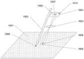
如图1所示为智能笔的工作示意图,为了便于说明智能笔的工作原理,图1省略了智能笔的外壳、结构支撑架及电路板等部件。其中,1001为印有坐标点阵码的纸张;1002为智能笔的笔芯;1003为镜头;1004为图像传感器;1005为图像传感器的像素阵列;1006为像素阵列1005经过镜头1003在纸面上的成像目标区域;1007为像素阵列的中心原点,其位于镜头1003的光轴上;1008为纸面上与1007相对应的目标点;1009为笔芯与纸面的接触点(即笔尖);1010为笔芯与纸面上的接触点1009经过镜头1003虚拟成像于图像传感器1004上的像。FIG. 1 is a working schematic diagram of the smart pen. In order to facilitate the description of the working principle of the smart pen, FIG. 1 omits components such as the housing, the structural support frame and the circuit board of the smart pen. Among them, 1001 is the paper printed with the coordinate lattice code; 1002 is the refill of the smart pen; 1003 is the lens; 1004 is the image sensor; 1005 is the pixel array of the image sensor; 1007 is the center origin of the pixel array, which is located on the optical axis of the
纸张1001印有坐标点阵码,所述坐标点阵码被解码后可得到相应的坐标,因此可认为纸张1001自带坐标信息。但由于笔芯1002与镜头1003在空间结构上的制约,使得镜头在纸面上的视野中心点1008与笔尖1009不能重合,并且不同的握笔姿势会导致笔身倾斜角度、笔身旋转角度、纸张旋转角度发生变化,也就是图像传感器1004与纸张1001的平面夹角、平面相对旋转角度是变化的,这样一来,即使固定笔尖1009于纸面不动,图像传感器的目标视野却是可以在一定范围内变化,因而解码得到的坐标值也是在一定范围内变化的。The
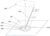
为了更直观的说明问题所在,请参见图2:固定笔尖1009于纸面上,保持笔芯1002与纸面夹角不变,笔身沿2001所示的圆形轨迹运动360°,相应的镜头视野中心1008在纸面上的运行轨迹2002必将是一个半径大于0的圆,因此智能笔采集到的原始笔迹坐标也必定是一个半径大于0的圆,然而笔芯在纸上留下的笔迹只是一个点。更进一步的,不同人的握笔姿态不同,使得笔芯1002与纸面1001夹角不同,轨迹2002的分布落在以笔尖1009为圆心的圆环面内,如2003所示,笔芯与纸面夹角越大,轨迹半径越小,如2004所示,笔芯与纸面夹角越小,轨迹半径越大。In order to explain the problem more intuitively, please refer to Figure 2: Fix the
为了更进一步直观形象的说明问题,请看图3A,图3A示出了两种不同空间姿态下,智能笔绘制的两条相切弧线,即弧线ab和弧线cd,实际上像素矩阵中心1007“看到”的弧线轨迹为a'b'和c'd'。理想情况下,电脑屏幕上重建的图形应如图3B中的(1)所示,然而一个非优化的设计方案往往导致如图3B中的(2)或图3B中的(3)所示结果:纸面上绘制的相切弧线在屏幕却显示为不相交的弧线。For a more intuitive and visual illustration of the problem, please refer to Figure 3A. Figure 3A shows two tangent arcs drawn by the smart pen under two different spatial attitudes, namely the arc ab and the arc cd. In fact, the pixel matrix The arc trajectories "seen" by
对于上述技术问题,CN201611188735.7公开了一种笔尖位置求解方法,其通过获取用户通过点击纸面中的第一点时拍摄的第一图像,以获取第一变换函数,然后依据第一变换函数和第一点的纸面坐标获取笔尖图像坐标。该技术方案通过点击一个点从而获取笔尖图像坐标,虽然具有计算量较小的优势,但没有考虑到当用户以不同的握笔姿势(即智能笔的空间姿态不同)进行书写时对笔尖图像坐标的影响。因此,当用户在实际书写时的握笔姿势与点击纸面中的第一点的握笔姿势不同时,其预先确定的笔尖图像坐标与笔尖实际成像于图像传感器1004的坐标将存在较大的误差,导致了对笔迹的还原精度较差。同时,点击第一点时,很难保证笔尖与第一点的完美契合,因此,对第一点只采集一次第一图像存在较大的采样误差,这也导致了预先确定的笔尖图像坐标存在较大的误差。更进一步的,在书写的过程中,握笔的姿态也往往会发生变化,这也导致了对笔迹的还原精度较差。For the above-mentioned technical problems, CN201611188735.7 discloses a method for solving the position of a pen tip, which obtains a first transformation function by obtaining a first image captured by a user by clicking a first point on the paper, and then according to the first transformation function and the paper coordinates of the first point to get the pen tip image coordinates. This technical solution obtains the image coordinates of the pen tip by clicking on a point. Although it has the advantage of less computation, it does not take into account that when the user writes in different pen-holding postures (that is, the spatial posture of the smart pen is different), the Impact. Therefore, when the user's pen-holding posture during actual writing is different from the pen-holding posture of clicking on the first point on the paper surface, the predetermined image coordinates of the pen tip and the coordinates of the actual image of the pen tip on the
发明内容SUMMARY OF THE INVENTION
有鉴于此,本发明实施例提供了智能笔笔尖图像坐标的求解方法、装置、介质及智能笔,用以解决现有技术中当握笔姿势发生变化时,所确定笔尖图像坐标误差较大的技术问题。In view of this, the embodiments of the present invention provide a method, device, medium, and smart pen for solving the image coordinates of the pen tip of a smart pen, so as to solve the problem of large errors in the determined pen tip image coordinates in the prior art when the pen-holding posture changes. technical problem.
第一方面,本发明实施例提供了一种智能笔笔尖图像坐标的求解方法,所述智能笔包括图像传感器,所述方法包括以下步骤:In a first aspect, an embodiment of the present invention provides a method for solving image coordinates of a smart pen tip, where the smart pen includes an image sensor, and the method includes the following steps:
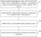
S1:控制所述图像传感器获取N帧第一图像,N为大于或等于2的正整数;其中,获取各帧所述第一图像时,所述智能笔的空间姿态均不相同且所述笔尖均位于书写介质的同一个预设点上;S1: Control the image sensor to acquire N frames of first images, where N is a positive integer greater than or equal to 2; wherein, when acquiring the first images of each frame, the spatial posture of the smart pen is different and the pen tip are located on the same preset point of the writing medium;
S2:根据各帧所述第一图像分别确定其对应的第一透视变换矩阵,以确定N个所述第一透视变换矩阵;S2: Determine the corresponding first perspective transformation matrices according to the first images of each frame, to determine N first perspective transformation matrices;
S3:根据N个所述第一透视变换矩阵构建笔尖图像坐标方程组;S3: constructing a pen tip image coordinate equation system according to the N first perspective transformation matrices;
S4:根据所述预设点的坐标和所述笔尖图像坐标方程组求解笔尖图像坐标。S4: Solve the pen tip image coordinates according to the coordinates of the preset point and the pen tip image coordinate equation system.
本发明实施例通过将笔尖置于预设点并采集N帧第一图像,且获取各帧所述第一图像时所述智能笔的空间姿态均不相同,然后根据各帧所述第一图像分别确定其对应的第一透视变换矩阵并构建笔尖图像坐标方程组。因此,基于该笔尖图像坐标方程组求解得到的笔尖图像坐标充分考虑了智能笔在不同空间姿态的影响,即该笔尖图像坐标较好的还原了不同握笔姿态下,笔尖实际成像于图像传感器1004的坐标。如此,即使是用户以不同的握笔姿态进行书写或者是不同用户(握笔姿态往往存在很大不同)进行书写,本发明实施例均能够较好的还原笔尖实际成像于图像传感器1004的坐标,从而有效解决现有技术中当握笔姿势发生变化时,所确定笔尖图像坐标误差较大的技术问题。In this embodiment of the present invention, the pen tip is placed at a preset point and N frames of first images are collected, and the spatial postures of the smart pen are different when acquiring the first images of each frame, and then according to the first images of each frame The corresponding first perspective transformation matrix is respectively determined and the pen tip image coordinate equation system is constructed. Therefore, the pen tip image coordinates obtained based on the solution of the pen tip image coordinate equation system fully consider the influence of the smart pen in different spatial postures, that is, the pen tip image coordinates better restore the actual image of the pen tip on the
优选地,所述书写介质包括以阵列形式排布的第一码点,所述第一图像包括与第一码点对应的第二码点,在S2:根据各帧所述第一图像分别确定其对应的第一透视变换矩阵,包括:Preferably, the writing medium includes first code points arranged in an array, and the first image includes a second code point corresponding to the first code point, and at S2: determine respectively according to each frame of the first image Its corresponding first perspective transformation matrix, including:
构建第一码点和第二码点的配对关系以确定至少4组配对点;constructing a pairing relationship between the first code point and the second code point to determine at least 4 sets of pairing points;
根据所述至少4组配对点确定第一图像所对应的第一透视变换矩阵;determining a first perspective transformation matrix corresponding to the first image according to the at least 4 groups of paired points;
其中,所述配对点包括在书写介质中沿第一方向排布的第一码点和沿第二方向排布的第一码点,所述第一方向和所述第二方向正交。Wherein, the pairing points include a first code point arranged along a first direction and a first code point arranged along a second direction in the writing medium, and the first direction and the second direction are orthogonal.
如前述,纸张1001(即本发明所称的书写介质)上印有点阵坐标码,即第一码点,所述第一码点包括以阵列形式排布的第一码点,具体包括在书写介质中沿第一方向排布的第一码点和沿第二方向排布的第一码点。在现有技术中,通常会对第一码点做一定的偏移处理,用于编码坐标信息,这导致所述第一码点的实际纸面坐标和名义纸面坐标存在误差,若以这些经过偏移处理的第一码点求解所述第一透视变换矩阵,则会降低所述第一透视变换矩阵的求解精度。因此,本发明实施例根据书写介质未经偏移处理的第一码点(即沿第一方向排布的第一码点和沿第二方向排布的第一码点)来求解所述第一透视变换矩阵,可确保求解精度。As mentioned above, the paper 1001 (that is, the writing medium referred to in the present invention) is printed with a dot matrix coordinate code, that is, the first code point, and the first code point includes the first code points arranged in the form of an array. A first code point arranged in a first direction and a first code point arranged in a second direction in the medium. In the prior art, a certain offset process is usually performed on the first code point to encode the coordinate information, which results in an error between the actual paper coordinates and the nominal paper coordinates of the first code point. To solve the first perspective transformation matrix from the offset-processed first code point, the solution precision of the first perspective transformation matrix will be reduced. Therefore, in the embodiment of the present invention, the first code point (ie, the first code point arranged along the first direction and the first code point arranged along the second direction) of the writing medium without offset processing is used to solve the first code point. A perspective transformation matrix to ensure solution accuracy.
优选地,所述笔尖图像坐标方程组为超定方程组,在S4:根据所述预设点的坐标和所述笔尖图像坐标方程组求解笔尖图像坐标中,包括:根据最小二乘法求解所述笔尖图像坐标的最优解。Preferably, the pen tip image coordinate equation system is an overdetermined equation system, and in S4: solving the pen tip image coordinates according to the coordinates of the preset point and the pen tip image coordinate equation system includes: solving the pen tip image coordinates according to a least squares method The optimal solution for the pen tip image coordinates.
获取的第一图像数量越多,则确定的第一透视变换矩阵也越多。相应的,笔尖图像坐标方程组中透视变换方程的个数也就越多。其中,每2个对应的透视变换方程即可确定笔尖图像坐标(每个透视变换方程的未知数均为笔尖图像坐标的横纵坐标),因此,当笔尖图像坐标方程组中透视变换方程的个数大于2时,所述笔尖图像坐标方程组即为超定方程组,根据最小二乘法可求得所述笔尖图像坐标的最优解,即所述最优解相对于各种握笔姿态的误差均较小。因此,采用本发明实施例的技术方案,无论采取何种握笔姿态,笔尖图像坐标均可以很好的还原笔尖实际成像于图像传感器1004的坐标。The greater the number of acquired first images, the more first perspective transformation matrices are determined. Correspondingly, the number of perspective transformation equations in the pen tip image coordinate equation system increases. Among them, every two corresponding perspective transformation equations can determine the pen tip image coordinates (the unknowns of each perspective transformation equation are the horizontal and vertical coordinates of the pen tip image coordinates), therefore, when the number of perspective transformation equations in the pen tip image coordinate equation system When it is greater than 2, the pen tip image coordinate equation system is an overdetermined equation system, and the optimal solution of the pen tip image coordinates can be obtained according to the least squares method, that is, the error of the optimal solution relative to various pen holding postures. are smaller. Therefore, with the technical solutions of the embodiments of the present invention, no matter what gesture of holding the pen is adopted, the image coordinates of the pen tip can well restore the coordinates of the actual image of the pen tip on the
优选地,定义三维空间坐标系,所述三维空间坐标系其中一个维度的坐标轴垂直于所述书写介质,记所述智能笔与第一维度的夹角为第一夹角,与第二维度的夹角为第二夹角,与第三维度的夹角为第三夹角,所述空间姿态包括所述第一夹角、所述第二夹角和所述第三夹角。Preferably, a three-dimensional space coordinate system is defined, the coordinate axis of one dimension of the three-dimensional space coordinate system is perpendicular to the writing medium, and the angle between the smart pen and the first dimension is the first angle, and the angle between the smart pen and the second dimension is the first angle. The included angle is the second included angle, the included angle with the third dimension is the third included angle, and the spatial posture includes the first included angle, the second included angle, and the third included angle.
本发明实施例以第一夹角、第二夹角以及第三夹角对空间姿态进行定义,可以较好的模拟用户对于智能笔的握持姿态,使得当握笔姿势发生变化时,所确定笔尖图像坐标可以很好的还原笔尖实际成像于图像传感器1004的坐标。In the embodiment of the present invention, the spatial posture is defined by the first included angle, the second included angle and the third included angle, which can better simulate the user's holding posture for the smart pen, so that when the pen-holding posture changes, the determined The image coordinates of the pen tip can well restore the coordinates of the actual image of the pen tip on the
优选地,在S1中,包括:所获取的N帧所述第一图像中至少包括相邻2帧所述第一图像在获取时的所述第一夹角、所述第二夹角以及所述第三夹角中的至少一项存在不同。Preferably, in S1, it includes: the acquired N frames of the first images at least include the first included angle, the second included angle, and all the first included angles of two adjacent frames of the first images when acquired. At least one of the third included angles is different.
本发明实施例通过改变第一夹角、所述第二夹角以及所述第三夹角中的至少一项,从而改变所述智能笔的空间姿态。在具体实施时,可通过用户操作对所述第一夹角、所述第二夹角以及所述第三夹角中的至少一项进行调整,也可通过用于调整上述夹角的装置对所述第一夹角、所述第二夹角以及所述第三夹角中的至少一项进行调整,当使用所述装置进行调整时,可将各个夹角的数值发送至对应的驱动机构中,实现对空间姿态的调整。In the embodiment of the present invention, the spatial posture of the smart pen is changed by changing at least one of the first included angle, the second included angle, and the third included angle. During specific implementation, at least one of the first included angle, the second included angle, and the third included angle can be adjusted through a user operation, or the device for adjusting the aforementioned included angle can be adjusted. At least one of the first included angle, the second included angle, and the third included angle is adjusted, and when the device is used for adjustment, the value of each included angle can be sent to the corresponding drive mechanism , to realize the adjustment of the spatial attitude.
优选地,在S4:根据所述预设点的坐标和所述笔尖图像坐标方程组求解笔尖图像坐标中,包括:Preferably, in S4: solving the pen tip image coordinates according to the coordinates of the preset point and the pen tip image coordinate equation set, including:
S41:计算所述笔尖图像坐标相对于预设坐标的误差;S41: Calculate the error of the pen tip image coordinates relative to the preset coordinates;
S42:判断所述误差与阈值之间的大小关系,以判断所述智能笔的校正状态。S42: Determine the magnitude relationship between the error and the threshold to determine the correction state of the smart pen.
智能笔在设计时,对于笔尖图像坐标会有一个设计值(即预设坐标),但光学和结构零部件存在加工公差和/或装配误差,同一设计规格的产出品,每支笔的设计值与真实值的之间必定存在误差。因此,本发明实施例通过计算笔尖图像坐标相对于预设坐标的误差,若误差小于阈值,则确定所述智能笔的校正状态为通过;若误差大于阈值,则确定所述智能笔的校正状态为失败。对于校正状态为失败的智能笔,可进行重复执行步骤S1至S4,以排除误检测。或者,对于校正状态为失败的智能笔可确定其为不良品,避免其流入市场。When the smart pen is designed, there will be a design value (ie preset coordinates) for the image coordinates of the pen tip, but there are machining tolerances and/or assembly errors for optical and structural parts, and the output products of the same design specifications, the design value of each pen There must be an error between the true value. Therefore, in the embodiment of the present invention, the error of the pen tip image coordinates relative to the preset coordinates is calculated. If the error is less than a threshold, the correction status of the smart pen is determined to pass; if the error is greater than the threshold, the correction status of the smart pen is determined. for failure. For the smart pen whose calibration status is failed, steps S1 to S4 may be repeatedly executed to eliminate false detection. Alternatively, a smart pen whose calibration status is failed can be determined to be a defective product to prevent it from entering the market.
优选地,在S4之后,所述方法还包括:Preferably, after S4, the method further includes:
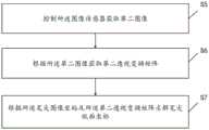
S5:控制所述图像传感器获取第二图像;S5: controlling the image sensor to acquire a second image;
S6:根据所述第二图像获取第二透视变换矩阵;S6: Acquire a second perspective transformation matrix according to the second image;
S7:根据所述笔尖图像坐标及所述第二透视变换矩阵求解笔尖纸面坐标。S7: Calculate the coordinates on the paper surface of the pen tip according to the pen tip image coordinates and the second perspective transformation matrix.
在确定了笔尖图像坐标之后,即可使用所述智能笔进行书写,在书写过程中,控制所述图像传感器获取第二图像并确定对应的第二透视变换矩阵,然后基于该第二透视变换矩阵以及笔尖图像坐标即可对笔尖纸面坐标进行求解。在连续的书写过程中,可连续采集多帧第二图像,从而确定多个笔尖纸面坐标,并基于时间的先后顺序,对书写的笔迹进行还原。即使是在连续书写的过程中发生握笔姿势的变化,本发明实施例的笔尖图像坐标也可以很好的适配,确保笔迹还原的精度。After the pen tip image coordinates are determined, the smart pen can be used to write. During the writing process, the image sensor is controlled to obtain a second image and a corresponding second perspective transformation matrix is determined, and then based on the second perspective transformation matrix and the pen tip image coordinates to solve the pen tip paper surface coordinates. During the continuous writing process, multiple frames of second images can be continuously collected, so as to determine the coordinates of multiple pen tips on the paper surface, and restore the written handwriting based on the time sequence. Even if the pen-holding posture changes during the continuous writing process, the image coordinates of the pen tip in the embodiment of the present invention can be well adapted to ensure the accuracy of handwriting restoration.
优选地,所述方法还包括:Preferably, the method further includes:
计算所述笔尖纸面坐标在不同空间姿态下的解码成功率;Calculate the decoding success rate of the pen tip paper coordinates under different spatial attitudes;
根据所述解码成功率确定智能笔的有效姿态工作范围。The effective gesture working range of the smart pen is determined according to the decoding success rate.
由于图像畸变等原因,智能笔对于笔尖纸面坐标的解码成功率很难达到100%。因此,本发明实施例通过计算所述笔尖纸面坐标在不同空间姿态下的解码成功率,并按照预先设定的阈值,从而确定智能笔的有效姿态工作范围。从而对于有效姿态工作范围不符合设计标准的智能笔进行测试和筛选,避免不良品流入市场。Due to image distortion and other reasons, it is difficult for the smart pen to decode the pen tip paper coordinates with a success rate of 100%. Therefore, the embodiment of the present invention determines the effective posture working range of the smart pen by calculating the decoding success rate of the pen tip paper coordinates under different spatial postures and according to a preset threshold. In this way, the smart pens whose effective posture working range does not meet the design standards are tested and screened to prevent defective products from entering the market.
第二方面,本发明实施例还提供一种智能笔笔尖图像坐标的求解装置,所述智能笔包括图像传感器,所述装置包括:In a second aspect, an embodiment of the present invention further provides a device for solving image coordinates of a smart pen tip, where the smart pen includes an image sensor, and the device includes:
控制模块,用于控制所述图像传感器获取N帧第一图像,N为大于或等于2的正整数;其中,获取各帧所述第一图像时,所述智能笔的空间姿态均不相同且所述笔尖均位于书写介质的同一个预设点上;A control module, configured to control the image sensor to acquire N frames of first images, where N is a positive integer greater than or equal to 2; wherein, when acquiring the first images of each frame, the spatial postures of the smart pen are all different and The nibs are all located on the same preset point of the writing medium;
第一透视矩阵确定模块,用于根据各帧所述第一图像分别确定其对应的第一透视变换矩阵,以确定N个所述第一透视变换矩阵;a first perspective matrix determining module, configured to determine the corresponding first perspective transformation matrices according to the first images of each frame, so as to determine N first perspective transformation matrices;
方程组构建模块,用于根据N个所述第一透视变换矩阵构建笔尖图像坐标方程组;an equation system building module, configured to build a pen tip image coordinate equation system according to the N first perspective transformation matrices;
解码模块,用于根据所述预设点的坐标和所述笔尖图像坐标方程组求解笔尖图像坐标。A decoding module, configured to solve the pen tip image coordinates according to the coordinates of the preset point and the pen tip image coordinate equation system.
第三方面,本发明实施例提供了一种存储介质,其上存储有计算机程序指令,当计算机程序指令被处理器执行时实现如上述实施方式中第一方面的方法。In a third aspect, an embodiment of the present invention provides a storage medium on which computer program instructions are stored, and when the computer program instructions are executed by a processor, the method of the first aspect in the foregoing embodiments is implemented.
第四方面,本发明实施例提供了一种智能笔,所述智能笔包括:至少一个处理器、至少一个存储器以及存储在存储器中的计算机程序指令,当计算机程序指令被处理器执行时实现如上述实施方式中第一方面的方法。In a fourth aspect, an embodiment of the present invention provides a smart pen, where the smart pen includes: at least one processor, at least one memory, and computer program instructions stored in the memory, and when the computer program instructions are executed by the processor, the The method of the first aspect in the above embodiment.
附图说明Description of drawings
为了更清楚地说明本发明实施例的技术方案,下面将对本发明实施例中所需要使用的附图作简单地介绍,对于本领域普通技术人员来讲,在不付出创造性劳动的前提下,还可以根据这些附图获得其他的附图,这些均在本发明的保护范围内。In order to illustrate the technical solutions of the embodiments of the present invention more clearly, the accompanying drawings required in the embodiments of the present invention will be briefly introduced below. For those of ordinary skill in the art, without creative work, the Other drawings can be obtained from these drawings, which are all within the protection scope of the present invention.
图1是现有技术中智能笔的工作原理示意图。FIG. 1 is a schematic diagram of the working principle of a smart pen in the prior art.
图2是现有技术中当智能笔的空间姿态发生变化时解码坐标的示意图。FIG. 2 is a schematic diagram of decoding coordinates when the spatial posture of the smart pen changes in the prior art.
图3A是现有技术中智能笔绘制的两条相切弧线的示意图。FIG. 3A is a schematic diagram of two tangent arcs drawn by a smart pen in the prior art.
图3B是对图3A中两条相切弧线还原效果示意图。FIG. 3B is a schematic diagram of the restoration effect of the two tangent arcs in FIG. 3A .
图4是本发明实施例提供的一种智能笔笔尖图像坐标的求解方法的流程示意图。FIG. 4 is a schematic flowchart of a method for solving image coordinates of a smart pen tip provided by an embodiment of the present invention.
图5是本发明实施例提供的一种笔尖在图像传感器上的成像示意图。FIG. 5 is a schematic diagram of imaging of a pen tip on an image sensor according to an embodiment of the present invention.
图6A是使用现有技术对笔迹进行还原的效果示意图。FIG. 6A is a schematic diagram of the effect of restoring handwriting by using the prior art.
图6B是使用本发明实施例对笔迹进行还原的效果示意图。FIG. 6B is a schematic diagram of the effect of restoring handwriting by using an embodiment of the present invention.
图7是本发明实施例提供的一种求解第一透视变换矩阵的方法流程示意图。FIG. 7 is a schematic flowchart of a method for solving a first perspective transformation matrix provided by an embodiment of the present invention.
图8是本发明实施例提供的一种求解第一透视变换矩阵的示意图。FIG. 8 is a schematic diagram of solving a first perspective transformation matrix according to an embodiment of the present invention.
图9是本发明实施例提供的一种智能笔空间姿态的示意图。FIG. 9 is a schematic diagram of a spatial posture of a smart pen provided by an embodiment of the present invention.
图10是本发明实施例提供的一种判断智能笔校正状态的方法流程示意图。FIG. 10 is a schematic flowchart of a method for judging a correction state of a smart pen provided by an embodiment of the present invention.
图11是本发明实施例提供的一种求解笔尖纸面坐标的方法流程示意图。11 is a schematic flowchart of a method for solving the coordinates of a pen tip on paper provided by an embodiment of the present invention.
图12是本发明实施例提供的一种确定智能笔有效姿态工作范围的方法流程示意图。FIG. 12 is a schematic flowchart of a method for determining an effective posture working range of a smart pen provided by an embodiment of the present invention.
图13是本发明实施例提供的一种智能笔笔尖图像坐标求解装置的结构示意图。FIG. 13 is a schematic structural diagram of a device for solving image coordinates of a smart pen tip provided by an embodiment of the present invention.
图14是本发明实施例提供的一种智能笔的结构示意图。FIG. 14 is a schematic structural diagram of a smart pen provided by an embodiment of the present invention.
图15是本发明实施例提供的一种智能笔校正装置的结构示意图。FIG. 15 is a schematic structural diagram of an apparatus for correcting a smart pen according to an embodiment of the present invention.
具体实施方式Detailed ways
下面将详细描述本发明的各个方面的特征和示例性实施例,为了使本发明的目的、技术方案及优点更加清楚明白,以下结合附图及实施例,对本发明进行进一步详细描述。应理解,此处所描述的具体实施例仅被配置为解释本发明,并不被配置为限定本发明。对于本领域技术人员来说,本发明可以在不需要这些具体细节中的一些细节的情况下实施。下面对实施例的描述仅仅是为了通过示出本发明的示例来提供对本发明更好的理解。The features and exemplary embodiments of various aspects of the present invention will be described in detail below. In order to make the objects, technical solutions and advantages of the present invention more clear, the present invention will be further described in detail below with reference to the accompanying drawings and embodiments. It should be understood that the specific embodiments described herein are only configured to explain the present invention, and are not configured to limit the present invention. It will be apparent to those skilled in the art that the present invention may be practiced without some of these specific details. The following description of the embodiments is only intended to provide a better understanding of the present invention by illustrating examples of the invention.
需要说明的是,在本文中,诸如第一和第二等之类的关系术语仅仅用来将一个实体或者操作与另一个实体或操作区分开来,而不一定要求或者暗示这些实体或操作之间存在任何这种实际的关系或者顺序。而且,术语“包括”、“包含”或者其任何其他变体意在涵盖非排他性的包含,从而使得包括一系列要素的过程、方法、物品或者设备不仅包括那些要素,而且还包括没有明确列出的其他要素,或者是还包括为这种过程、方法、物品或者设备所固有的要素。在没有更多限制的情况下,由语句“包括……”限定的要素,并不排除在包括所述要素的过程、方法、物品或者设备中还存在另外的相同要素。It should be noted that, in this document, relational terms such as first and second are only used to distinguish one entity or operation from another entity or operation, and do not necessarily require or imply any relationship between these entities or operations. any such actual relationship or sequence exists. Moreover, the terms "comprising", "comprising" or any other variation thereof are intended to encompass a non-exclusive inclusion such that a process, method, article or device that includes a list of elements includes not only those elements, but also includes not explicitly listed or other elements inherent to such a process, method, article or apparatus. Without further limitation, an element defined by the phrase "comprises" does not preclude the presence of additional identical elements in a process, method, article, or device that includes the element.
如前述,现有技术中的笔尖位置求解方法缺少对于智能笔空间姿态的考虑,导致求解得到的笔尖图像位置无法很好适配不同的空间姿态。As mentioned above, the pen tip position solution method in the prior art lacks consideration of the spatial posture of the smart pen, resulting in that the obtained pen tip image position cannot be well adapted to different spatial postures.
有鉴于此,本发明实施例提供了一种智能笔笔尖图像坐标的求解方法,请参见图4,是该方法的流程示意图,具体包括如下步骤。In view of this, an embodiment of the present invention provides a method for solving image coordinates of a smart pen tip. Please refer to FIG. 4 , which is a schematic flowchart of the method, which specifically includes the following steps.
S1:控制所述图像传感器获取,N为大于或等于2的正整数;其中,获取各帧所述第一图像时,所述智能笔的空间姿态均不相同且所述笔尖均位于书写介质的同一个预设点上;S1: control the image sensor to acquire, N is a positive integer greater than or equal to 2; wherein, when acquiring the first image of each frame, the spatial posture of the smart pen is different and the pen tip is located on the writing medium. on the same preset point;
S2:根据各帧所述第一图像分别确定其对应的第一透视变换矩阵,以确定N个所述第一透视变换矩阵;S2: Determine the corresponding first perspective transformation matrices according to the first images of each frame, to determine N first perspective transformation matrices;
S3:根据N个所述第一透视变换矩阵构建笔尖图像坐标方程组;S3: constructing a pen tip image coordinate equation system according to the N first perspective transformation matrices;
S4:根据所述预设点的坐标和所述笔尖图像坐标方程组求解笔尖图像坐标。S4: Solve the pen tip image coordinates according to the coordinates of the preset point and the pen tip image coordinate equation system.
如图1所示,因为笔芯1002、镜头1003、图像传感器1004均固定在刚性结构件上,无论笔身处于何种空间姿态,对于确定的设计参数,笔尖1009经过镜头虚拟成像后在图像传感器1004上也必有一个对应的设计值(即笔尖图像坐标)。如图5所示,以1007为原点在图像传感器1004上构建平面直角坐标系,设笔尖所成的像1010距离原点的水平距离为h微米、垂直距离为v微米,图像传感器1004的单个像素水平边长为s微米,垂直边长为t微米,则笔尖图像坐标的设计值为(x,y)=(h/s,v/t)。As shown in FIG. 1 , because the
在本发明一种实施方式中,镜头1003的参数设计会保证笔尖1009不成像于图像传感器像素阵列1005中,否则会降低图像传感器的像素利用率,甚至是不成像于整个图像传感器1004,但这并不影响本发明的实现,因为本发明不会真正使用笔尖1009的光学图像。In an embodiment of the present invention, the parameter design of the
在本发明一种实施方式中,图像传感器可采用高帧率图像传感器以提升图像的采集速度。In one embodiment of the present invention, the image sensor may use a high frame rate image sensor to improve the image acquisition speed.
书写介质可以为纸张、陶瓷、塑料、显示屏等任意平面。书写介质上印刷或打印有对人眼近似隐形的第一码点,具体的排布方式并不具体限定,所述第一码点均对应有相应的坐标。所述预设点为第一码点,因此所述预设点的坐标为已知的,为便于描述记为(C0,R0)。The writing medium can be any plane such as paper, ceramics, plastics, and display screens. The writing medium is printed or printed with first code points that are nearly invisible to the human eye, and the specific arrangement is not particularly limited, and the first code points all have corresponding coordinates. The preset point is the first code point, so the coordinates of the preset point are known, and are denoted as (C0 , R0 ) for the convenience of description.
因此,本发明实施例将智能笔的笔尖置于预设点(C0,R0)上,并不断的调整智能笔的空间姿态,在不同的空间姿态下,控制所述图像传感器获取第一图像,最终获取N帧第一图像。所述第一码点在图像传感器成像为第二码点,因此所述第一图像包括与第一码点对应的第二码点。Therefore, in the embodiment of the present invention, the tip of the smart pen is placed on a preset point (C0 , R0 ), and the spatial posture of the smart pen is continuously adjusted, and under different spatial postures, the image sensor is controlled to obtain the first image, and finally obtain N frames of the first image. The first code point is imaged as a second code point on the image sensor, so the first image includes a second code point corresponding to the first code point.
受限于图像传感器和书写介质的角度关系,图像传感器所采集的图像存在一定畸变,需要进行校正,可根据透视变换(Perspective Transformation)原理进行校正。具体的,运用透视变换方程进行校正,所述透视变换方程为:Limited by the angular relationship between the image sensor and the writing medium, the image collected by the image sensor has a certain distortion, which needs to be corrected, which can be corrected according to the principle of perspective transformation (Perspective Transformation). Specifically, the perspective transformation equation is used for correction, and the perspective transformation equation is:

其等价于:It is equivalent to:

其中,C表示书写介质上第一码点的横坐标,R表示书写介质上第一码点的纵坐标。x表示第一图像上第二码点的横坐标,y表示第一图像上第二码点的纵坐标。m0、m1、m2、m3、m4、m5、m6、m7、m8构成一个3行3列的第一透视变换矩阵M。其中,
如前述,第二码点和第一码点存在一一对应的关系,因此,在第一码点和第二码点的坐标均已知的情况下,根据上述公式(2)即可求得第一透视变换矩阵M。因此,根据N帧第一图像可求得N个第一透视变换矩阵M。各个第一透视变换矩阵M可采取如下技术方案进行求解:As mentioned above, there is a one-to-one correspondence between the second code point and the first code point. Therefore, when the coordinates of the first code point and the second code point are known, it can be obtained according to the above formula (2). The first perspective transformation matrix M. Therefore, N first perspective transformation matrices M can be obtained according to the first images of N frames. Each first perspective transformation matrix M can be solved by adopting the following technical solutions:
在第一图像中选取至少4个第二码点,并确定这4个第二码点所对应的第一码点。其中,第二码点的坐标可对第一图像进行分析或者测量得到,而第一码点的坐标是已知的。例如,选取的第二码点数量为4,将这8个点(4个第一码点和4个第二码点)的坐标代入前述公式(2),即可得到包括8个透视变换方程的方程组,而未知数为9个。此时,所有透视变换方程可除以同一个未知数,例如均除以m8,即所述方程组只包括8个未知数,根据所述方程组即可求得第一透视变换矩阵M。需要特别说明的是,所选取的第二码点的数量越多,数据内含的统计信息越稳定,方程组求解的精度越高。线性方程组的最优求解是图像处理技术领域技术人员的基础理论知识,此处不再赘言。因此,对N帧所述第一图像均按照上述技术方案进行求解,即可确定N个第一透视变换矩阵。At least four second code points are selected in the first image, and the first code points corresponding to the four second code points are determined. The coordinates of the second code point can be obtained by analyzing or measuring the first image, and the coordinates of the first code point are known. For example, if the number of selected second code points is 4, and the coordinates of these 8 points (4 first code points and 4 second code points) are substituted into the aforementioned formula (2), the equations including 8 perspective transformations can be obtained. , and there are 9 unknowns. At this time, all perspective transformation equations can be divided by the same unknown, for example, by m8, that is, the equation set only includes 8 unknowns, and the first perspective transformation matrix M can be obtained according to the equation set. It should be noted that, the greater the number of selected second code points, the more stable the statistical information contained in the data, and the higher the accuracy of solving the equation system. The optimal solution of the system of linear equations is the basic theoretical knowledge of those skilled in the field of image processing technology, and will not be repeated here. Therefore, N first perspective transformation matrices can be determined by solving the N frames of the first images according to the above technical solution.
在得到N个第一透视变换矩阵之后,即可求解笔尖图像坐标。具体求解还是利用透视变换原理,在第一透视变换矩阵M确定之后,由于预设点的坐标(C0,R0)已知,根据上述透视变换方程,即可确定笔尖图像坐标。显而易见的是,根据一个第一透视变换矩阵M就可以求得笔尖图像坐标,但是仅用一个第一透视变换矩阵M进行求解,没有考虑到不同空间姿态下的误差,求解得到的笔尖图像坐标难以在不同空间姿态下实现对笔迹的高精度还原。因此,本发明实施例根据N个第一透视变换矩阵M,构建笔尖图像坐标方程组,以求取所述笔尖图像坐标在不同空间姿态下的最优解。若所述笔尖图像坐标方程组为超定方程组,则根据最小二乘法求解所述笔尖图像坐标的最优解。After the N first perspective transformation matrices are obtained, the pen tip image coordinates can be solved. The specific solution is to use the perspective transformation principle. After the first perspective transformation matrix M is determined, since the coordinates of the preset point (C0 , R0 ) are known, the pen tip image coordinates can be determined according to the above perspective transformation equation. It is obvious that the pen tip image coordinates can be obtained according to a first perspective transformation matrix M, but only a first perspective transformation matrix M is used to solve the problem, without considering the errors under different spatial attitudes, the obtained pen tip image coordinates are difficult to solve. Realize high-precision restoration of handwriting under different spatial poses. Therefore, the embodiment of the present invention constructs a pen tip image coordinate equation system according to N first perspective transformation matrices M, so as to obtain the optimal solution of the pen tip image coordinates under different spatial attitudes. If the pen tip image coordinate equation system is an overdetermined equation system, the optimal solution of the pen tip image coordinates is solved according to the least square method.
具体的,上述公式(2)等价于:Specifically, the above formula (2) is equivalent to:

其中,令:a00=(m0-m6*C);Among them, let: a00=(m0-m6*C);
a01=(m1-m7*C);a01=(m1-m7*C);
a10=(m3-m6*R);a10=(m3-m6*R);
a11=(m4-m7*R);a11=(m4-m7*R);
b0=-(m2-m8*C);b0=-(m2-m8*C);
b1=-(m5-m8*R);b1=-(m5-m8*R);
则公式(3)等价于:Then formula (3) is equivalent to:

现有N个第一透视变换矩阵,即有N组a00、a01、a10和a11,因此,代入公式(4)可得包括2N个方程的笔尖图像坐标方程组,具体为:There are N first perspective transformation matrices, that is, there are N groups of a00, a01, a10 and a11. Therefore, by substituting formula (4), a pen tip image coordinate equation system including 2N equations can be obtained, specifically:

因此,根据最小二乘法对公式(5)进行求解,得到笔尖图像坐标(x,y)的最优解。Therefore, formula (5) is solved according to the least square method, and the optimal solution of the pen tip image coordinates (x, y) is obtained.
综上所述,本发明实施例通过将笔尖置于预设点并采集N帧第一图像,且获取各帧所述第一图像时所述智能笔的空间姿态均不相同,然后根据各帧所述第一图像分别确定其对应的第一透视变换矩阵并构建笔尖图像坐标方程组。因此,基于该笔尖图像坐标方程组求解得到的笔尖图像坐标充分考虑了智能笔在不同空间姿态的影响,即该笔尖图像坐标较好的还原了不同握笔姿态下,笔尖实际成像于图像传感器1004的坐标。如此,即使是用户以不同的握笔姿态进行书写或者是不同用户(握笔姿态往往存在很大不同)进行书写,本发明实施例均能够较好的还原笔尖实际成像于图像传感器1004的坐标,从而有效解决现有技术中当握笔姿势发生变化时,所确定笔尖图像坐标误差较大的技术问题。具体的,为更加直观的说明本发明的技术效果,请参见图6A和图6B。图6A为使用设计值作为笔尖图像坐标对笔迹进行还原的还原效果(即没有考虑智能笔处于不同空间姿态的误差),从图6A可直观看出,书写在纸面上的笔迹基本位于表格内,而还原出来的笔迹却有部分位于表格外部,还原效果较差。图6B为采用本发明实施例求解得到笔迹图像坐标对笔迹进行还原的还原效果示意图,还原得到的笔迹均位于表格内部,还原的效果显然优于图6A。To sum up, in this embodiment of the present invention, the pen tip is placed at a preset point and N frames of first images are collected, and the spatial posture of the smart pen is different when each frame of the first image is obtained, and then according to each frame The first images respectively determine their corresponding first perspective transformation matrices and construct a pen tip image coordinate equation system. Therefore, the pen tip image coordinates obtained based on the solution of the pen tip image coordinate equation system fully consider the influence of the smart pen in different spatial postures, that is, the pen tip image coordinates better restore the actual image of the pen tip on the
请参见图7,本发明实施例还提供另一种求解第一透视变换矩阵的方法,具体包括以下步骤:Referring to FIG. 7 , an embodiment of the present invention further provides another method for solving the first perspective transformation matrix, which specifically includes the following steps:
S21:构建第一码点和第二码点的配对关系以确定至少4组配对点;S21: construct a pairing relationship between the first code point and the second code point to determine at least 4 sets of pairing points;
S22:根据所述至少4组配对点确定第一图像所对应的第一透视变换矩阵;S22: Determine a first perspective transformation matrix corresponding to the first image according to the at least 4 groups of paired points;
其中,所述配对点包括在书写介质中沿第一方向排布的第一码点和沿第二方向排布的第一码点,所述第一方向和所述第二方向正交。Wherein, the pairing points include a first code point arranged along a first direction and a first code point arranged along a second direction in the writing medium, and the first direction and the second direction are orthogonal.
为便于理解,请参见图8,x轴和y轴构成的平面坐标系为图像坐标系,其中各个码点为第二码点,C轴和R轴构成的平面坐标系为纸面坐标系,其中各个码点为第一码点。在构建配对关系时,仍需确定至少4组配对点,在本发明实施例中配对点的选择如下:选择虚线Ci穿过的第二码点和虚线Ri穿过的第二码点以及其对应的第一码点作为配对点,显而易见的是,所选择的配对点包括沿C轴方向排布的第一码点和沿R轴方向排布的第一码点。For ease of understanding, please refer to Figure 8, the plane coordinate system formed by the x-axis and the y-axis is the image coordinate system, wherein each code point is the second code point, and the plane coordinate system formed by the C-axis and the R-axis is the paper coordinate system, Each of the code points is the first code point. When constructing a pairing relationship, at least 4 groups of pairing points still need to be determined. In this embodiment of the present invention, the selection of the pairing points is as follows: select the second code point that the dotted line Ci passes through, the second code point that the dotted line Ri passes through, and Its corresponding first code point is used as a pairing point, and it is obvious that the selected pairing point includes a first code point arranged along the C-axis direction and a first code point arranged along the R-axis direction.
如图8所示,所述配对点共包括25个所述第一码点以及所述第一码点对应的第二码点,每组配对点均代入公式(2),即可得到包括50个方程的方程组,以求得第一透视变换矩阵的最优解。As shown in FIG. 8 , the pairing points include a total of 25 first code points and the second code points corresponding to the first code points. Each pairing point is substituted into formula (2), and it can be obtained that there are 50 A system of equations to obtain the optimal solution of the first perspective transformation matrix.
请参见图9,是本发明实施提供的一种空间姿态的示意图。定义三维空间坐标系,所述三维空间坐标系其中一个维度的坐标轴垂直于所述书写介质,记所述智能笔与第一维度的夹角为第一夹角,与第二维度的夹角为第二夹角,与第三维度的夹角为第三夹角,所述空间姿态包括所述第一夹角、所述第二夹角和所述第三夹角。Please refer to FIG. 9 , which is a schematic diagram of a spatial attitude provided by the implementation of the present invention. Define a three-dimensional space coordinate system, the coordinate axis of one dimension of the three-dimensional space coordinate system is perpendicular to the writing medium, and record the angle between the smart pen and the first dimension as the first angle, and the angle with the second dimension. is the second included angle, the included angle with the third dimension is the third included angle, and the spatial posture includes the first included angle, the second included angle, and the third included angle.
如图9所示,定义以纸平面行方向为b轴、列方向为a轴、纸面垂直向上方向为e轴的三维坐标空间,原点O位于坐标(C0,R0)处,定义笔芯与a轴的夹角为α、与b轴的夹角为β、与e轴的夹角为γ,即(α,β,γ)完全定义了笔身相对坐标纸的空间姿态,可以较好的模拟用户对于智能笔的握持姿态,使得当握笔姿势发生变化时,所确定笔尖图像坐标可以很好的还原笔尖实际成像于图像传感器1004的坐标。As shown in Figure 9, define a three-dimensional coordinate space with the row direction of the paper plane as the b axis, the column direction as the a axis, and the vertical upward direction of the paper surface as the e axis. The origin O is located at the coordinates (C0 , R0 ), and the pen is defined The included angle between the core and the a-axis is α, the included angle with the b-axis is β, and the included angle with the e-axis is γ, that is, (α, β, γ) completely defines the space attitude of the pen body relative to the coordinate paper, which can be compared It is good to simulate the user's holding posture of the smart pen, so that when the pen-holding posture changes, the determined image coordinates of the pen tip can well restore the coordinates of the actual image of the pen tip on the
在本发明一种实施方式中,在S1中,包括:所获取的N帧所述第一图像中至少包括相邻2帧所述第一图像在获取时的所述第一夹角、所述第二夹角以及所述第三夹角中的至少一项存在不同。In an embodiment of the present invention, in S1, it includes: the acquired N frames of the first images at least include the first included angle of two adjacent frames of the first images at the time of acquisition, the At least one of the second included angle and the third included angle is different.
具体的,相邻2帧第一图像是指连续获取的2帧第一图像。在具体实施时,可通过手动的方式对所述第一夹角、所述第二夹角以及所述第三夹角中的至少一项进行调整,也可通过自动化设备对所述第一夹角、所述第二夹角以及所述第三夹角中的至少一项进行调整。因此,本发明实施例还提供了一种如15所示的智能笔校正装置,其可用于调整所述第一夹角、所述第二夹角以及所述第三夹角,智能笔校正装置的具体实现请参见后文的描述。Specifically, the two adjacent frames of the first images refer to two consecutive frames of the first images. During specific implementation, at least one of the first included angle, the second included angle, and the third included angle can be adjusted manually, or the first included angle can be adjusted by automated equipment. at least one of the angle, the second included angle and the third included angle is adjusted. Therefore, an embodiment of the present invention also provides a smart pen correction device as shown in 15, which can be used to adjust the first included angle, the second included angle, and the third included angle, a smart pen correction device For the specific implementation, please refer to the description below.
请参见图10,在本发明一种实施方式中,还提供一种判断智能笔校正状态的方法,包括以下步骤。Referring to FIG. 10 , in an embodiment of the present invention, a method for judging the correction state of a smart pen is further provided, including the following steps.
S41:计算所述笔尖图像坐标相对于预设坐标的误差;S41: Calculate the error of the pen tip image coordinates relative to the preset coordinates;
S42:判断所述误差与阈值之间的大小关系,以判断所述智能笔的校正状态。S42: Determine the magnitude relationship between the error and the threshold to determine the correction state of the smart pen.
如前述,每支智能笔在设计时均有一个笔尖图像坐标的设计值,但因为光学和结构零部件存在加工公差和装配误差,同一设计规格的产出品,每支笔的真实值与设计值之间必定存在误差,因此需要对笔尖图像坐标的真实值进行求解。通过结合图4所描述的方法,已求得了笔尖图像坐标的真实值。此时,可计算所述笔尖图像坐标相对于预设坐标的误差,并判断该误差是否在许可范围内,若是则可以认为该智能笔为合格品且校正通过,若否,则认为校正不通过,需要再次以S1至S4的步骤进行校正或者确定其为不良品,进行重新装配或其它工序。As mentioned above, each smart pen has a design value of the image coordinates of the pen tip when it is designed. However, due to the processing tolerance and assembly error of optical and structural components, the output products of the same design specification, the actual value of each pen and the design value There must be errors between them, so it is necessary to solve the real values of the pen tip image coordinates. By the method described in conjunction with FIG. 4, the true values of the pen tip image coordinates have been obtained. At this time, the error of the image coordinates of the pen tip relative to the preset coordinates can be calculated, and it can be judged whether the error is within the allowable range. If so, the smart pen can be considered as a qualified product and the calibration has passed. , it needs to be corrected again in the steps S1 to S4 or it is determined as a defective product, and reassembly or other processes are carried out.
请参见图11,是本发明实施例提供的一种求解笔尖纸面坐标的方法流程示意图,包括以下步骤。Please refer to FIG. 11 , which is a schematic flowchart of a method for solving the coordinates of a pen tip on paper provided by an embodiment of the present invention, including the following steps.
S5:控制所述图像传感器获取第二图像;S5: controlling the image sensor to acquire a second image;
S6:根据所述第二图像获取第二透视变换矩阵;S6: Acquire a second perspective transformation matrix according to the second image;
S7:根据所述笔尖图像坐标及所述第二透视变换矩阵求解笔尖纸面坐标。S7: Calculate the coordinates on the paper surface of the pen tip according to the pen tip image coordinates and the second perspective transformation matrix.
具体的,通过结合图4所描述的方法,已经确定了笔尖图像坐标,此时可对笔尖纸面坐标进行求解以还原笔迹。其中,将笔尖置于所述书写介质任意一点时,控制所述图像传感器获取第二图像,根据所述第二图像获取第二透视变换矩阵,第二透视变换矩阵的获取方法可参见前述实施例,此处不再赘言。然后根据前述的公式(1),由于笔尖图像坐标和第二透视变换矩阵均为已知的,即可求得笔尖纸面坐标。进一步的,在进行连续书写时,控制所述图像传感器获取多帧第二图像,按照本实施例的方法求解对应的笔尖纸面坐标,根据各个笔尖纸面坐标即可还原笔迹。Specifically, through the method described in conjunction with FIG. 4 , the image coordinates of the pen tip have been determined, and at this time, the coordinates of the paper surface of the pen tip can be solved to restore the handwriting. Wherein, when the pen tip is placed at any point on the writing medium, the image sensor is controlled to acquire a second image, and a second perspective transformation matrix is acquired according to the second image. For the acquisition method of the second perspective transformation matrix, refer to the foregoing embodiments , will not be repeated here. Then, according to the aforementioned formula (1), since both the pen tip image coordinates and the second perspective transformation matrix are known, the pen tip paper surface coordinates can be obtained. Further, during continuous writing, the image sensor is controlled to acquire multiple frames of second images, the corresponding pen tip paper coordinates are obtained according to the method of this embodiment, and the handwriting can be restored according to the pen tip paper coordinates.
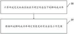
请参见图12,是本发明实施例提供的一种确定智能笔有效姿态工作范围的方法流程示意图,确定智能笔有效姿态工作范围的方法包括以下步骤。Please refer to FIG. 12 , which is a schematic flowchart of a method for determining an effective posture working range of a smart pen provided by an embodiment of the present invention. The method for determining the effective posture working range of a smart pen includes the following steps.
S8:计算所述笔尖纸面坐标在不同空间姿态下的解码成功率;S8: Calculate the decoding success rates of the pen tip paper coordinates under different spatial attitudes;
S9:根据所述解码成功率确定智能笔的有效姿态工作范围。S9: Determine the effective posture working range of the smart pen according to the decoding success rate.
具体的,智能笔对于笔尖纸面坐标的解码成功率并不总是100%,特别是在空间姿态为极端值的情况下。因此,本发明实施例通过获取笔尖纸面坐标在不同空间姿态下的解码成功率,以确定智能笔的有效姿态工作范围。例如,设定解码成功率在90%以上为有效工作范围,通过以正交实验设计方式遍历α、β、γ的取值组合,从而确定解码成功率在90%以上的取值,则对应的空间姿态范围为有效姿态工作范围。Specifically, the decoding success rate of the pen tip paper coordinates by the smart pen is not always 100%, especially when the spatial pose is an extreme value. Therefore, the embodiments of the present invention determine the effective posture working range of the smart pen by obtaining the decoding success rates of the pen tip paper coordinates under different spatial postures. For example, setting the decoding success rate above 90% as the effective working range, and traversing the value combinations of α, β, and γ in an orthogonal experimental design manner, to determine the value of the decoding success rate above 90%, then the corresponding The space attitude range is the effective attitude working range.
还需要特别说明的是,本发明中的公式(1)、公式(2)、公式(3)以及公式(4)是等价的,仅是为了便于理解在形式上做了变形。显然,本领域技术人员还可以进行其它等价变形,均应视为和本发明相同的技术方案。It should also be noted that the formula (1), formula (2), formula (3) and formula (4) in the present invention are equivalent, and are only modified in form for the convenience of understanding. Obviously, those skilled in the art can also make other equivalent modifications, which should be regarded as the same technical solutions as the present invention.
请参见图13,是本发明实施例提供的一种智能笔笔尖图像坐标的求解装置的结构示意图,所述装置包括:Please refer to FIG. 13 , which is a schematic structural diagram of a device for solving image coordinates of a smart pen tip provided by an embodiment of the present invention. The device includes:
控制模块,用于控制所述图像传感器获取N帧第一图像,N为大于或等于2的正整数;其中,获取各帧所述第一图像时,所述智能笔的空间姿态均不相同且所述笔尖均位于书写介质的同一个预设点上;A control module, configured to control the image sensor to acquire N frames of first images, where N is a positive integer greater than or equal to 2; wherein, when acquiring the first images of each frame, the spatial postures of the smart pen are all different and The nibs are all located on the same preset point of the writing medium;
第一透视矩阵确定模块,用于根据各帧所述第一图像分别确定其对应的第一透视变换矩阵,以确定N个所述第一透视变换矩阵;a first perspective matrix determining module, configured to determine the corresponding first perspective transformation matrices according to the first images of each frame, so as to determine N first perspective transformation matrices;
方程组构建模块,用于根据N个所述第一透视变换矩阵构建笔尖图像坐标方程组;an equation system building module, configured to build a pen tip image coordinate equation system according to the N first perspective transformation matrices;
解码模块,用于根据所述预设点的坐标和所述笔尖图像坐标方程组求解笔尖图像坐标。A decoding module, configured to solve the pen tip image coordinates according to the coordinates of the preset point and the pen tip image coordinate equation system.
另外,本发明实施例的智能笔笔尖图像坐标的求解方法可以由智能笔来实现。图14示出了本发明实施例提供的智能笔的硬件结构示意图。In addition, the method for solving the image coordinates of the smart pen tip according to the embodiment of the present invention may be implemented by a smart pen. FIG. 14 shows a schematic diagram of a hardware structure of a smart pen provided by an embodiment of the present invention.
智能笔可以包括处理器以及存储有计算机程序指令的存储器。A smart pen may include a processor and a memory storing computer program instructions.
具体地,上述处理器可以包括中央处理器(CPU),或者特定集成电路(ApplicationSpecific Integrated Circuit,ASIC),或者可以被配置成实施本发明实施例的一个或多个集成电路。Specifically, the above-mentioned processor may include a central processing unit (CPU), or a specific integrated circuit (Application Specific Integrated Circuit, ASIC), or may be configured to implement one or more integrated circuits of the embodiments of the present invention.
存储器可以包括用于数据或指令的大容量存储器。举例来说而非限制,存储器可包括硬盘驱动器(Hard Disk Drive,HDD)、软盘驱动器、闪存、光盘、磁光盘、磁带或通用串行总线(Universal Serial Bus,USB)驱动器或者两个或更多个以上这些的组合。在合适的情况下,存储器可包括可移除或不可移除(或固定)的介质。在合适的情况下,存储器可在数据处理装置的内部或外部。在特定实施例中,存储器是非易失性固态存储器。在特定实施例中,存储器包括只读存储器(ROM)。在合适的情况下,该ROM可以是掩模编程的ROM、可编程ROM(PROM)、可擦除PROM(EPROM)、电可擦除PROM(EEPROM)、电可改写ROM(EAROM)或闪存或者两个或更多个以上这些的组合。Memory may include mass storage for data or instructions. By way of example and not limitation, memory may include a Hard Disk Drive (HDD), floppy disk drive, flash memory, optical disk, magneto-optical disk, magnetic tape or Universal Serial Bus (USB) drive or two or more a combination of more than one of these. Storage may include removable or non-removable (or fixed) media, where appropriate. Where appropriate, the memory may be internal or external to the data processing device. In certain embodiments, the memory is non-volatile solid state memory. In certain embodiments, the memory includes read only memory (ROM). Where appropriate, the ROM may be a mask programmed ROM, programmable ROM (PROM), erasable PROM (EPROM), electrically erasable PROM (EEPROM), electrically rewritable ROM (EAROM) or flash memory or A combination of two or more of the above.
处理器通过读取并执行存储器中存储的计算机程序指令,以实现上述实施例中的任意一种智能笔笔尖图像坐标的求解方法。The processor reads and executes the computer program instructions stored in the memory to implement any one of the methods for solving the image coordinates of the smart pen tip in the above-mentioned embodiments.
在一个示例中,智能笔还可包括通信接口和总线。其中,如图14所示,处理器、存储器、通信接口通过总线连接并完成相互间的通信。In one example, the smart pen may also include a communication interface and a bus. Among them, as shown in FIG. 14 , the processor, the memory, and the communication interface are connected through a bus and complete the mutual communication.
通信接口,主要用于实现本发明实施例中各模块、装置、单元和/或设备之间的通信。The communication interface is mainly used to implement communication between modules, apparatuses, units, and/or devices in the embodiments of the present invention.
总线包括硬件、软件或两者,将智能笔的部件彼此耦接在一起。举例来说而非限制,总线可包括加速图形端口(AGP)或其他图形总线、增强工业标准架构(EISA)总线、前端总线(FSB)、超传输(HT)互连、工业标准架构(ISA)总线、无限带宽互连、低引脚数(LPC)总线、存储器总线、微信道架构(MCA)总线、外围组件互连(PCI)总线、PCI-Express(PCI-X)总线、串行高级技术附件(SATA)总线、视频电子标准协会局部(VLB)总线或其他合适的总线或者两个或更多个以上这些的组合。在合适的情况下,总线可包括一个或多个总线。尽管本发明实施例描述和示出了特定的总线,但本发明考虑任何合适的总线或互连。The bus includes hardware, software, or both, coupling the components of the smartpen to each other. By way of example and not limitation, the bus may include Accelerated Graphics Port (AGP) or other graphics bus, Enhanced Industry Standard Architecture (EISA) bus, Front Side Bus (FSB), HyperTransport (HT) Interconnect, Industry Standard Architecture (ISA) Bus, Infiniband Interconnect, Low Pin Count (LPC) Bus, Memory Bus, Microchannel Architecture (MCA) Bus, Peripheral Component Interconnect (PCI) Bus, PCI-Express (PCI-X) Bus, Serial Advanced Technology Attachment (SATA) bus, Video Electronics Standards Association Local (VLB) bus or other suitable bus or a combination of two or more of the above. Where appropriate, a bus may include one or more buses. Although embodiments of the present invention describe and illustrate a particular bus, the present invention contemplates any suitable bus or interconnect.
另外,结合上述实施例中的智能笔笔尖图像坐标的求解方法,本发明实施例可提供一种计算机可读存储介质来实现。该计算机可读存储介质上存储有计算机程序指令;该计算机程序指令被处理器执行时实现上述实施例中的任意一种智能笔笔尖图像坐标的求解方法。In addition, in combination with the method for solving the image coordinates of the smart pen tip in the above embodiment, the embodiment of the present invention can provide a computer-readable storage medium for implementation. Computer program instructions are stored on the computer-readable storage medium; when the computer program instructions are executed by the processor, any method for solving the image coordinates of the smart pen tip in the above-mentioned embodiments is implemented.
需要明确的是,本发明并不局限于上文所描述并在图中示出的特定配置和处理。为了简明起见,这里省略了对已知方法的详细描述。在上述实施例中,描述和示出了若干具体的步骤作为示例。但是,本发明的方法过程并不限于所描述和示出的具体步骤,本领域的技术人员可以在领会本发明的精神后,作出各种改变、修改和添加,或者改变步骤之间的顺序。It is to be understood that the present invention is not limited to the specific arrangements and processes described above and shown in the figures. For the sake of brevity, detailed descriptions of known methods are omitted here. In the above-described embodiments, several specific steps are described and shown as examples. However, the method process of the present invention is not limited to the specific steps described and shown, and those skilled in the art can make various changes, modifications and additions, or change the sequence of steps after comprehending the spirit of the present invention.
以上所述的结构框图中所示的功能块可以实现为硬件、软件、固件或者它们的组合。当以硬件方式实现时,其可以例如是电子电路、专用集成电路(ASIC)、适当的固件、插件、功能卡等等。当以软件方式实现时,本发明的元素是被用于执行所需任务的程序或者代码段。程序或者代码段可以存储在机器可读介质中,或者通过载波中携带的数据信号在传输介质或者通信链路上传送。“机器可读介质”可以包括能够存储或传输信息的任何介质。机器可读介质的例子包括电子电路、半导体存储器设备、ROM、闪存、可擦除ROM(EROM)、软盘、CD-ROM、光盘、硬盘、光纤介质、射频(RF)链路,等等。代码段可以经由诸如因特网、内联网等的计算机网络被下载。The functional blocks shown in the above-described structural block diagrams may be implemented as hardware, software, firmware, or a combination thereof. When implemented in hardware, it may be, for example, an electronic circuit, an application specific integrated circuit (ASIC), suitable firmware, a plug-in, a function card, or the like. When implemented in software, elements of the invention are programs or code segments used to perform the required tasks. The program or code segments may be stored in a machine-readable medium or transmitted over a transmission medium or communication link by a data signal carried in a carrier wave. A "machine-readable medium" may include any medium that can store or transmit information. Examples of machine-readable media include electronic circuits, semiconductor memory devices, ROM, flash memory, erasable ROM (EROM), floppy disks, CD-ROMs, optical disks, hard disks, fiber optic media, radio frequency (RF) links, and the like. The code segments may be downloaded via a computer network such as the Internet, an intranet, or the like.
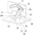
如图15所示,是本发明实施例提供一种智能笔校正装置的结构示意图,该装置包括转动件10、第一驱动机构20、第二驱动机构30、第三驱动机构40和支撑件50:转动件10设置有预设行列坐标的第一码点和用于固定智能笔100的笔尖的固定结构;第一驱动机构20的输出端与所述转动件10传动连接,所述第一驱动机构20用于驱动转动件10绕第三方向转动;第二驱动机构30用于与智能笔100传动连接,并驱动所述智能笔100绕第四方向转动;第三驱动机构40的输出端与所述第二驱动机构30形成传动连接,所述第三驱动机构40用于驱动第二驱动机构30沿以预设轴线为中心的圆弧运动;支撑件50用于支撑第一驱动机构20和第三驱动机构40。As shown in FIG. 15 , it is a schematic structural diagram of a smart pen calibration device provided by an embodiment of the present invention. The device includes a rotating
其中第一驱动机构20可以采用电机,为了便于描述,在本文中第一驱动机构20的电机为第一电机。转动件10可以采用转盘的形式,第一电机的定子部分固定前述支撑件50上,转子部分与转盘连接,具体可以将第一电机的输出轴与转盘固定连接。这样第一电机转子转动就可以带动转盘绕轴转子转动的轴线(即第三方向)转动。转盘上需要与智能笔100接触的一面印有第一码点,智能笔100通过识别该第一码点来获取笔尖相对转盘的位置。The
同理,第二驱动机构30和第三驱动机构40也可以采用电机,其中第二驱动机构30所采用的电机为第二电机,第三驱动机构40所采用的电机为第三电机,第三电机的定子部分可以固定在前述支撑件50上。Similarly, the
第二电机的转子与智能笔100形成传动连接,第二电机的转子将动力传递给智能笔100,带动智能笔100转动。前述第四方向即转子转动的轴线所在的方向。The rotor of the second motor forms a transmission connection with the
其中第三驱动机构40带动第二驱动机构30沿着某一段设定的圆弧运动,从而带动智能笔100一起运动。The
为了便于第三驱动机构40带动第二驱动机构30沿圆弧运动,本实施例的装置还包括摆动件60,所述摆动件60一端与第三驱动机构40传动连接,相对的另一端与第二驱动机构30形成连接,所述摆动件60在第三驱动机构40驱动下以预设轴线为摆动中心摆动。其中摆动件60可以是摆臂,摆臂的一端与第三电机的转子连接。另一端通过中间连接件80例如螺栓和第二电机的定子部分连接。具体可以使螺栓的一端与摆臂远离第三电机的移动固定连接,另一端与第二电机的定子固定。摆臂的长度以及与第二电机和第三电机的位置关系满足第三电机驱动摆臂转动时,第二电机在摆臂的带动下沿预定的圆弧转动,该圆弧的圆心与第三电机转子的转动轴线重合。这样当第三电机转子转动时候就带动摆臂绕着第三电机转子的轴线摆动,从而带动第二电机沿以第三电机转子轴线为中心的圆弧运动。In order to facilitate the
第一电机的运动范围为360°,本实施例利用第一驱动机构20驱动转盘转动来模拟人手握智能笔100书写时纸张平面相对智能笔100在360°范围内的所有旋转角度。第二电机的运动范围为±180°往复运动转动或者任意角度的转动。当智能笔100通过有线方式与控制器连接时则采用±180°往复运动转动,当智能笔100通过无线方式与控制器连接时则可以不限制转动的角度。本实施例利用第二驱动机构30的带动智能笔100的转动来模拟智能笔100相对握手的所有旋转角度。第三电机的运动方式为±K°往复运动,其中±K°大于智能笔100的正常工作倾角,智能笔100垂直于转盘角度定义为0°,本实施例利用第三驱动机构40来模拟人手握智能笔100书写,智能笔100相对纸面的所有夹角。The movement range of the first motor is 360°. In this embodiment, the
此外,在本实施例中还包括控制器,所述控制器分别与第一驱动机构20、第二驱动机构30和第三驱动机构40电连接。控制器根据测试要求或者校正要求,控制第一驱动机构20、第二驱动机构30和第三驱动机构40分别转动设定的角度和方向,来精确控制智能笔100的空间姿态,从而在智能笔100的测试和校正过程中准确模拟人手握笔书写时智能笔100相对握手和书写纸的姿态。在对智能笔100进行校正和测试时可以利用设置在转盘上的固定结构将笔尖固定在转盘预先设定的位置上。前述转动件10上的固定结构可以为设置在所述转动件10表面的凹点。In addition, in this embodiment, a controller is also included, and the controller is electrically connected to the
在另外一种实施方式中,如图15所示,所述装置还包括约束轨迹为圆弧的导轨70,所述导轨70用于约束第二驱动机构30沿以预设轴线为中心的圆弧运动。该导轨70上设置有圆弧形的导槽71,所述中间连接件80一端与所述第二驱动机构30连接,相对的另一端穿过所述圆弧形的导槽71后与所述摆动件60远离第三驱动机构40的一端连接。为了提高校正和测试时智能笔100做圆弧运动时的可靠性和准确性,本发明设置了导轨70,使第二驱动机构30在导轨70的约束下可以准确地沿着以设定的轴线为中心的圆弧运动,使本装置对智能笔100的校正和测试更加地准确。本实施例的导轨70可以是一块安装在支撑件50上的平板状的部件,在该部件上开设一端圆弧形的导槽71作为导轨70。该圆弧形导槽71的圆心的位置与第三电机输出轴的位置重合,用来连接第二电机和摆臂的中间连接件80的中间一段卡在圆弧形导槽71中。当第三电机带动摆臂摆动时,由于导槽71对中间连接件80的约束作用,中间连接件80在摆臂的带动下准确地沿着理想的圆弧轨迹运动,最终带动待测试或者待校正的智能笔100做准确地圆弧运动。其中中间连接件80可以采用具有圆柱形的外表面的部件,例如螺栓,导槽71的宽度与该圆柱形的直径相匹配,该圆柱形的轴线与第三电机输出轴的轴线平行。In another embodiment, as shown in FIG. 15 , the device further includes a
在另外一种实施方式中,如图15所示,在本实施中,所述第二驱动机构30的输出端还设置有夹持件31,所述夹持件31用于夹持智能笔100。本实施例的装置可以设置一个夹子,该夹子与第二电机的输出轴形成连接。利用增设的夹子可以夹住智能笔100的尾部,使第二驱动机构30可以稳定地驱动智能笔100运动。此外采用既可以松开智能笔100又可以夹紧智能笔100的夹持件31可以方便地对智能笔100进行上料和下料作业,大大提高了智能笔100测试和校正的效率。In another embodiment, as shown in FIG. 15 , in this embodiment, the output end of the
在本实施例中第三电机的输出轴的轴线和第一电机输出轴的轴线可以采用相互垂直的方式进行安装。对此,本实施例中的支撑件50包括相互垂直的第一固定面和第二固定面,所述第一驱动机构20与第一固定面连接,所述第三驱动机构40和第二固定面连接。本实施例的装置可以将支撑件50设置为“L”型,使支撑件50具有两个相互垂直的面即第一固定面和第二固定面,然后分别将第一电机和第三电机安装在第一固定面和第二固定面上,以使第三电机的输出轴的轴线和第一电机输出轴的轴线相互垂直。In this embodiment, the axis of the output shaft of the third motor and the axis of the output shaft of the first motor may be installed in a mutually perpendicular manner. In this regard, the
作为另一种实现方式,支撑件50也可以采用底座52和“L”型支架51的组合,所述“L”型支架51的一个面与所述底座52连接,另一个面与所述底座52的上表面相垂直,所述第三驱动机构40安装在“L”型支架51与底座52的上表面相垂直的面上。底座52可以采用平板形状的平台,该平台具有一个水平面,第一电机的定子部分安装在该水平面上。第一电机的输出轴竖直朝上与转动件10连接。同时在底座52的水平面上安装一个“L”型支架51的支架,该支架的一个面水平放置并固定在底座52的水平面上,另外一个面竖直设置,第三电机的定子部分便安装在该竖直设置的面上。As another implementation manner, the
需要特别说明的是,图15中的部分结构在实现时可省略或者用其它结构代替,实现相同的技术效果。It should be noted that some structures in FIG. 15 may be omitted or replaced with other structures during implementation, so as to achieve the same technical effect.
基于图15所示的智能笔校正装置,本发明实施例还提供一种调整智能笔空间姿态的方法,包括以下步骤:Based on the smart pen calibration device shown in FIG. 15 , an embodiment of the present invention further provides a method for adjusting the spatial posture of a smart pen, including the following steps:
获取第一角度值、第二角度值以及第三角度值;Obtain the first angle value, the second angle value and the third angle value;
分别发送所述第一角度值、所述第二角度值以及第三角度值至所述第一驱动机构、所述第二驱动机构以及所述第三驱动机构;其中,所述第一角度值用于控制所述第一驱动机构的停车位置,所述第二角度值用于控制所述第二驱动机构的停车位置,所述第三角度值用于控制所述第三驱动机构的停车位置。Send the first angle value, the second angle value and the third angle value to the first driving mechanism, the second driving mechanism and the third driving mechanism respectively; wherein, the first angle value used to control the parking position of the first driving mechanism, the second angle value is used to control the parking position of the second driving mechanism, and the third angle value is used to control the parking position of the third driving mechanism .
因此,本发明实施例通过第一角度值、第二角度值以及第三角度值,从而实现对所述第一驱动机构、所述第二驱动机构以及所述第三机构的运动控制,进而实现对第一夹角、第二夹角以及第三夹角的控制。Therefore, the embodiment of the present invention realizes the motion control of the first driving mechanism, the second driving mechanism and the third mechanism through the first angle value, the second angle value and the third angle value, thereby realizing the Control of the first, second, and third angles.
进一步的,第一角度值、第二角度值以及第三角度值可从预先设定好的角度表中获取。Further, the first angle value, the second angle value and the third angle value can be obtained from a preset angle table.
在本发明一种实施方式中,所述控制器可采用上位机进行实现,所述上位机与所述智能笔校正装置构成智能笔校正系统。In an embodiment of the present invention, the controller may be implemented by a host computer, and the host computer and the smart pen correction device constitute a smart pen correction system.
所述第一驱动机构、所述第二驱动机构和所述第三驱动机构接收所述上位机发送的角度值,以控制所述智能笔的空间姿态。所述角度值包括所述第一角度值、所述第二角度值以及所述第三角度值。The first driving mechanism, the second driving mechanism and the third driving mechanism receive the angle value sent by the host computer to control the spatial posture of the smart pen. The angle values include the first angle value, the second angle value, and the third angle value.
所述上位机与所述第一驱动机构、所述第二驱动机构和所述第三驱动机构可以为有线连接或者无线通讯。The upper computer and the first driving mechanism, the second driving mechanism and the third driving mechanism may be wired or communicated wirelessly.
采用该实施例所述的技术方案,可精准控制智能笔的空间姿态,便于执行结合图4进行描述的技术方案或者结合图12进行描述的技术方案,以实现自动化求解所述笔尖图像坐标或自动确定所述智能笔的有效姿态工作范围。Using the technical solution described in this embodiment, the spatial posture of the smart pen can be precisely controlled, and it is convenient to implement the technical solution described in conjunction with FIG. 4 or the technical solution described in conjunction with FIG. Determine the effective gesture working range of the smart pen.
还需要说明的是,本发明中提及的示例性实施例,基于一系列的步骤或者装置描述一些方法或系统。但是,本发明不局限于上述步骤的顺序,也就是说,可以按照实施例中提及的顺序执行步骤,也可以不同于实施例中的顺序,或者若干步骤同时执行。It should also be noted that the exemplary embodiments mentioned in the present invention describe some methods or systems based on a series of steps or devices. However, the present invention is not limited to the order of the above steps, that is, the steps may be performed in the order mentioned in the embodiments, or may be different from the order in the embodiments, or several steps may be performed simultaneously.
以上所述,仅为本发明的具体实施方式,所属领域的技术人员可以清楚地了解到,为了描述的方便和简洁,上述描述的系统、模块和单元的具体工作过程,可以参考前述方法实施例中的对应过程,在此不再赘述。应理解,本发明的保护范围并不局限于此,任何熟悉本技术领域的技术人员在本发明揭露的技术范围内,可轻易想到各种等效的修改或替换,这些修改或替换都应涵盖在本发明的保护范围之内。The above are only specific implementations of the present invention. Those skilled in the art can clearly understand that, for the convenience and simplicity of the description, the specific working process of the above-described systems, modules and units may refer to the foregoing method embodiments. The corresponding process in , will not be repeated here. It should be understood that the protection scope of the present invention is not limited to this. Any person skilled in the art can easily think of various equivalent modifications or replacements within the technical scope disclosed by the present invention, and these modifications or replacements should all cover within the protection scope of the present invention.
Claims (11)
Priority Applications (1)
| Application Number | Priority Date | Filing Date | Title |
|---|---|---|---|
| CN202011049168.3ACN112132080B (en) | 2020-09-29 | 2020-09-29 | Method, device, medium and smart pen for solving image coordinates of smart pen tip |
Applications Claiming Priority (1)
| Application Number | Priority Date | Filing Date | Title |
|---|---|---|---|
| CN202011049168.3ACN112132080B (en) | 2020-09-29 | 2020-09-29 | Method, device, medium and smart pen for solving image coordinates of smart pen tip |
Related Child Applications (1)
| Application Number | Title | Priority Date | Filing Date |
|---|---|---|---|
| CN202510614394.8ADivisionCN120808350A (en) | 2020-09-29 | Intelligent pen nib positioning method and device and intelligent pen |
Publications (2)
| Publication Number | Publication Date |
|---|---|
| CN112132080Atrue CN112132080A (en) | 2020-12-25 |
| CN112132080B CN112132080B (en) | 2025-05-09 |
Family
ID=73844715
Family Applications (1)
| Application Number | Title | Priority Date | Filing Date |
|---|---|---|---|
| CN202011049168.3AActiveCN112132080B (en) | 2020-09-29 | 2020-09-29 | Method, device, medium and smart pen for solving image coordinates of smart pen tip |
Country Status (1)
| Country | Link |
|---|---|
| CN (1) | CN112132080B (en) |
Cited By (4)
| Publication number | Priority date | Publication date | Assignee | Title |
|---|---|---|---|---|
| CN112433628A (en)* | 2021-01-28 | 2021-03-02 | 深圳市瑞立视多媒体科技有限公司 | Rigid body pose determination method and device of double-light-ball interactive pen and computer equipment |
| CN113031793A (en)* | 2021-04-06 | 2021-06-25 | 维沃移动通信有限公司 | Contour acquisition method and device and intelligent pen |
| CN113569842A (en)* | 2021-07-13 | 2021-10-29 | 读书郎教育科技有限公司 | Method for positioning and acquiring handwriting based on pen point |
| CN114648768A (en)* | 2022-05-24 | 2022-06-21 | 江西三有果科技有限公司 | Image frame-based handwriting trajectory extraction method, device, storage medium and device |
Citations (4)
| Publication number | Priority date | Publication date | Assignee | Title |
|---|---|---|---|---|
| CN1637774A (en)* | 2004-01-06 | 2005-07-13 | 微软公司 | Camera-pen-tip mapping and calibration |
| US20100232681A1 (en)* | 2009-03-12 | 2010-09-16 | Omron Corporation | Three-dimensional vision sensor |
| CN108198216A (en)* | 2017-12-12 | 2018-06-22 | 深圳市神州云海智能科技有限公司 | A kind of robot and its position and orientation estimation method and device based on marker |
| CN109141226A (en)* | 2018-06-06 | 2019-01-04 | 华南农业大学 | The spatial point coordinate measuring method of one camera multi-angle |
- 2020
- 2020-09-29CNCN202011049168.3Apatent/CN112132080B/enactiveActive
Patent Citations (4)
| Publication number | Priority date | Publication date | Assignee | Title |
|---|---|---|---|---|
| CN1637774A (en)* | 2004-01-06 | 2005-07-13 | 微软公司 | Camera-pen-tip mapping and calibration |
| US20100232681A1 (en)* | 2009-03-12 | 2010-09-16 | Omron Corporation | Three-dimensional vision sensor |
| CN108198216A (en)* | 2017-12-12 | 2018-06-22 | 深圳市神州云海智能科技有限公司 | A kind of robot and its position and orientation estimation method and device based on marker |
| CN109141226A (en)* | 2018-06-06 | 2019-01-04 | 华南农业大学 | The spatial point coordinate measuring method of one camera multi-angle |
Non-Patent Citations (2)
| Title |
|---|
| 张绍兵: "基于靶标的三目视觉3维坐标测量系统", 激光技术, no. 04, 25 July 2013 (2013-07-25), pages 523 - 528* |
| 武良辰: "系统辨识", 28 February 1994, 焦作矿业学院, pages: 15* |
Cited By (8)
| Publication number | Priority date | Publication date | Assignee | Title |
|---|---|---|---|---|
| CN112433628A (en)* | 2021-01-28 | 2021-03-02 | 深圳市瑞立视多媒体科技有限公司 | Rigid body pose determination method and device of double-light-ball interactive pen and computer equipment |
| CN113268149A (en)* | 2021-01-28 | 2021-08-17 | 深圳市瑞立视多媒体科技有限公司 | Rigid body pose determination method and device of double-light-ball interactive pen and computer equipment |
| CN113268149B (en)* | 2021-01-28 | 2024-04-16 | 深圳市瑞立视多媒体科技有限公司 | Rigid body pose determining method and device of double-light ball interactive pen and computer equipment |
| CN113031793A (en)* | 2021-04-06 | 2021-06-25 | 维沃移动通信有限公司 | Contour acquisition method and device and intelligent pen |
| CN113031793B (en)* | 2021-04-06 | 2024-05-31 | 维沃移动通信有限公司 | Contour collection method, device and smart pen |
| CN113569842A (en)* | 2021-07-13 | 2021-10-29 | 读书郎教育科技有限公司 | Method for positioning and acquiring handwriting based on pen point |
| CN113569842B (en)* | 2021-07-13 | 2023-09-26 | 读书郎教育科技有限公司 | Method for positioning and obtaining handwriting based on pen point |
| CN114648768A (en)* | 2022-05-24 | 2022-06-21 | 江西三有果科技有限公司 | Image frame-based handwriting trajectory extraction method, device, storage medium and device |
Also Published As
| Publication number | Publication date |
|---|---|
| CN112132080B (en) | 2025-05-09 |
Similar Documents
| Publication | Publication Date | Title |
|---|---|---|
| CN112132080A (en) | Method, device, medium and smart pen for solving image coordinates of smart pen tip | |
| CN109993798B (en) | Method and equipment for detecting motion trail by multiple cameras and storage medium | |
| CN107808400B (en) | Camera calibration system and calibration method thereof | |
| US20140100694A1 (en) | System and method for camera-based auto-alignment | |
| CN113706621B (en) | Mark point positioning and posture obtaining method and system based on marked image | |
| CN114029982B (en) | A hand-eye calibration device and calibration method for a camera outside a robotic arm | |
| CN109813336A (en) | Inertial measurement unit calibration method | |
| CN102096923A (en) | Fisheye calibration method and device | |
| CN109263253A (en) | Crystal silicon photovoltaic solar battery printing locating platform scaling method and device based on machine vision | |
| CN112917513A (en) | TCP calibration method of three-dimensional dispensing needle head based on machine vision | |
| CN112489133A (en) | Calibration method, device and equipment of hand-eye system | |
| CN110465946A (en) | Simple easily pixel coordinate and robot coordinate relationship scaling method | |
| CN113814987B (en) | Multi-camera robot hand-eye calibration method, device, electronic device and storage medium | |
| CN108429908A (en) | A kind of test method of camera module, device, equipment and medium | |
| CN115731306A (en) | Camera calibration system and method | |
| CN106767902A (en) | A kind of star sensor principal point measurement apparatus and its method | |
| CN115365979A (en) | Optical processing tool calibration method, device, computer equipment and readable storage medium | |
| CN111076761B (en) | Magnetic encoder calibration method and system | |
| CN107756391A (en) | The bearing calibration of mechanical arm correction system | |
| CN108038871A (en) | The pivot of rotating platform determines method, apparatus, server and storage medium | |
| CN120808350A (en) | Intelligent pen nib positioning method and device and intelligent pen | |
| CN214704583U (en) | Intelligent pen correcting device and testing device | |
| CN110570414B (en) | A method, device, electronic device and storage medium for obtaining an alignment reference | |
| CN112684792A (en) | Two-dimensional code array label detection method and storage device | |
| CN116886881B (en) | Projector based on omnidirectional trapezoidal technology |
Legal Events
| Date | Code | Title | Description |
|---|---|---|---|
| PB01 | Publication | ||
| PB01 | Publication | ||
| SE01 | Entry into force of request for substantive examination | ||
| SE01 | Entry into force of request for substantive examination | ||
| GR01 | Patent grant | ||
| GR01 | Patent grant |