CN112128301A - A hydraulic shock absorber - Google Patents
A hydraulic shock absorberDownload PDFInfo
- Publication number
- CN112128301A CN112128301ACN202010786279.6ACN202010786279ACN112128301ACN 112128301 ACN112128301 ACN 112128301ACN 202010786279 ACN202010786279 ACN 202010786279ACN 112128301 ACN112128301 ACN 112128301A
- Authority
- CN
- China
- Prior art keywords
- hydraulic shock
- liquid
- shock absorption
- infusion
- cylinder
- Prior art date
- Legal status (The legal status is an assumption and is not a legal conclusion. Google has not performed a legal analysis and makes no representation as to the accuracy of the status listed.)
- Granted
Links
- 230000035939shockEffects0.000titleclaimsabstractdescription98
- 239000006096absorbing agentSubstances0.000titledescription17
- 239000007788liquidSubstances0.000claimsabstractdescription99
- 238000010521absorption reactionMethods0.000claimsabstractdescription60
- 238000001802infusionMethods0.000claimsabstractdescription55
- 239000000725suspensionSubstances0.000claimsabstractdescription26
- XLYOFNOQVPJJNP-UHFFFAOYSA-NwaterSubstancesOXLYOFNOQVPJJNP-UHFFFAOYSA-N0.000claimsdescription33
- 238000013016dampingMethods0.000claimsdescription29
- 230000001050lubricating effectEffects0.000claimsdescription28
- 238000001816coolingMethods0.000claimsdescription14
- 239000000110cooling liquidSubstances0.000claimsdescription9
- 238000007789sealingMethods0.000claimsdescription7
- 238000009434installationMethods0.000claimsdescription3
- 230000013011matingEffects0.000claims3
- 239000003978infusion fluidSubstances0.000claims1
- 230000005540biological transmissionEffects0.000abstractdescription9
- 239000012530fluidSubstances0.000description20
- 239000002826coolantSubstances0.000description12
- 238000000034methodMethods0.000description10
- 230000000694effectsEffects0.000description8
- 230000008569processEffects0.000description7
- 238000010586diagramMethods0.000description6
- 238000005096rolling processMethods0.000description3
- 238000005452bendingMethods0.000description2
- 230000006835compressionEffects0.000description2
- 238000007906compressionMethods0.000description2
- 238000005461lubricationMethods0.000description2
- 230000032258transportEffects0.000description2
- 230000009286beneficial effectEffects0.000description1
- 238000013461designMethods0.000description1
- 238000011161developmentMethods0.000description1
- 230000006872improvementEffects0.000description1
- 230000004048modificationEffects0.000description1
- 238000012986modificationMethods0.000description1
- 230000009467reductionEffects0.000description1
Images


Classifications
- F—MECHANICAL ENGINEERING; LIGHTING; HEATING; WEAPONS; BLASTING
- F16—ENGINEERING ELEMENTS AND UNITS; GENERAL MEASURES FOR PRODUCING AND MAINTAINING EFFECTIVE FUNCTIONING OF MACHINES OR INSTALLATIONS; THERMAL INSULATION IN GENERAL
- F16F—SPRINGS; SHOCK-ABSORBERS; MEANS FOR DAMPING VIBRATION
- F16F15/00—Suppression of vibrations in systems; Means or arrangements for avoiding or reducing out-of-balance forces, e.g. due to motion
- F16F15/02—Suppression of vibrations of non-rotating, e.g. reciprocating systems; Suppression of vibrations of rotating systems by use of members not moving with the rotating systems
- F16F15/023—Suppression of vibrations of non-rotating, e.g. reciprocating systems; Suppression of vibrations of rotating systems by use of members not moving with the rotating systems using fluid means
- F—MECHANICAL ENGINEERING; LIGHTING; HEATING; WEAPONS; BLASTING
- F01—MACHINES OR ENGINES IN GENERAL; ENGINE PLANTS IN GENERAL; STEAM ENGINES
- F01P—COOLING OF MACHINES OR ENGINES IN GENERAL; COOLING OF INTERNAL-COMBUSTION ENGINES
- F01P3/00—Liquid cooling
- F—MECHANICAL ENGINEERING; LIGHTING; HEATING; WEAPONS; BLASTING
- F16—ENGINEERING ELEMENTS AND UNITS; GENERAL MEASURES FOR PRODUCING AND MAINTAINING EFFECTIVE FUNCTIONING OF MACHINES OR INSTALLATIONS; THERMAL INSULATION IN GENERAL
- F16F—SPRINGS; SHOCK-ABSORBERS; MEANS FOR DAMPING VIBRATION
- F16F13/00—Units comprising springs of the non-fluid type as well as vibration-dampers, shock-absorbers, or fluid springs
- F16F13/005—Units comprising springs of the non-fluid type as well as vibration-dampers, shock-absorbers, or fluid springs comprising both a wound spring and a damper, e.g. a friction damper
- F16F13/007—Units comprising springs of the non-fluid type as well as vibration-dampers, shock-absorbers, or fluid springs comprising both a wound spring and a damper, e.g. a friction damper the damper being a fluid damper
- F—MECHANICAL ENGINEERING; LIGHTING; HEATING; WEAPONS; BLASTING
- F16—ENGINEERING ELEMENTS AND UNITS; GENERAL MEASURES FOR PRODUCING AND MAINTAINING EFFECTIVE FUNCTIONING OF MACHINES OR INSTALLATIONS; THERMAL INSULATION IN GENERAL
- F16F—SPRINGS; SHOCK-ABSORBERS; MEANS FOR DAMPING VIBRATION
- F16F15/00—Suppression of vibrations in systems; Means or arrangements for avoiding or reducing out-of-balance forces, e.g. due to motion
- F16F15/02—Suppression of vibrations of non-rotating, e.g. reciprocating systems; Suppression of vibrations of rotating systems by use of members not moving with the rotating systems
- F16F15/022—Suppression of vibrations of non-rotating, e.g. reciprocating systems; Suppression of vibrations of rotating systems by use of members not moving with the rotating systems using dampers and springs in combination
- F—MECHANICAL ENGINEERING; LIGHTING; HEATING; WEAPONS; BLASTING
- F16—ENGINEERING ELEMENTS AND UNITS; GENERAL MEASURES FOR PRODUCING AND MAINTAINING EFFECTIVE FUNCTIONING OF MACHINES OR INSTALLATIONS; THERMAL INSULATION IN GENERAL
- F16F—SPRINGS; SHOCK-ABSORBERS; MEANS FOR DAMPING VIBRATION
- F16F15/00—Suppression of vibrations in systems; Means or arrangements for avoiding or reducing out-of-balance forces, e.g. due to motion
- F16F15/02—Suppression of vibrations of non-rotating, e.g. reciprocating systems; Suppression of vibrations of rotating systems by use of members not moving with the rotating systems
- F16F15/04—Suppression of vibrations of non-rotating, e.g. reciprocating systems; Suppression of vibrations of rotating systems by use of members not moving with the rotating systems using elastic means
- F16F15/06—Suppression of vibrations of non-rotating, e.g. reciprocating systems; Suppression of vibrations of rotating systems by use of members not moving with the rotating systems using elastic means with metal springs
- F16F15/067—Suppression of vibrations of non-rotating, e.g. reciprocating systems; Suppression of vibrations of rotating systems by use of members not moving with the rotating systems using elastic means with metal springs using only wound springs
- F—MECHANICAL ENGINEERING; LIGHTING; HEATING; WEAPONS; BLASTING
- F16—ENGINEERING ELEMENTS AND UNITS; GENERAL MEASURES FOR PRODUCING AND MAINTAINING EFFECTIVE FUNCTIONING OF MACHINES OR INSTALLATIONS; THERMAL INSULATION IN GENERAL
- F16F—SPRINGS; SHOCK-ABSORBERS; MEANS FOR DAMPING VIBRATION
- F16F9/00—Springs, vibration-dampers, shock-absorbers, or similarly-constructed movement-dampers using a fluid or the equivalent as damping medium
- F16F9/10—Springs, vibration-dampers, shock-absorbers, or similarly-constructed movement-dampers using a fluid or the equivalent as damping medium using liquid only; using a fluid of which the nature is immaterial
- F16F9/14—Devices with one or more members, e.g. pistons, vanes, moving to and fro in chambers and using throttling effect
- F16F9/16—Devices with one or more members, e.g. pistons, vanes, moving to and fro in chambers and using throttling effect involving only straight-line movement of the effective parts
- F16F9/18—Devices with one or more members, e.g. pistons, vanes, moving to and fro in chambers and using throttling effect involving only straight-line movement of the effective parts with a closed cylinder and a piston separating two or more working spaces therein
- F16F9/19—Devices with one or more members, e.g. pistons, vanes, moving to and fro in chambers and using throttling effect involving only straight-line movement of the effective parts with a closed cylinder and a piston separating two or more working spaces therein with a single cylinder and of single-tube type
- F—MECHANICAL ENGINEERING; LIGHTING; HEATING; WEAPONS; BLASTING
- F16—ENGINEERING ELEMENTS AND UNITS; GENERAL MEASURES FOR PRODUCING AND MAINTAINING EFFECTIVE FUNCTIONING OF MACHINES OR INSTALLATIONS; THERMAL INSULATION IN GENERAL
- F16F—SPRINGS; SHOCK-ABSORBERS; MEANS FOR DAMPING VIBRATION
- F16F9/00—Springs, vibration-dampers, shock-absorbers, or similarly-constructed movement-dampers using a fluid or the equivalent as damping medium
- F16F9/32—Details
- F16F9/3207—Constructional features
- F16F9/3235—Constructional features of cylinders
- F—MECHANICAL ENGINEERING; LIGHTING; HEATING; WEAPONS; BLASTING
- F16—ENGINEERING ELEMENTS AND UNITS; GENERAL MEASURES FOR PRODUCING AND MAINTAINING EFFECTIVE FUNCTIONING OF MACHINES OR INSTALLATIONS; THERMAL INSULATION IN GENERAL
- F16F—SPRINGS; SHOCK-ABSORBERS; MEANS FOR DAMPING VIBRATION
- F16F9/00—Springs, vibration-dampers, shock-absorbers, or similarly-constructed movement-dampers using a fluid or the equivalent as damping medium
- F16F9/32—Details
- F16F9/34—Special valve constructions; Shape or construction of throttling passages
- F16F9/3405—Throttling passages in or on piston body, e.g. slots
- F—MECHANICAL ENGINEERING; LIGHTING; HEATING; WEAPONS; BLASTING
- F16—ENGINEERING ELEMENTS AND UNITS; GENERAL MEASURES FOR PRODUCING AND MAINTAINING EFFECTIVE FUNCTIONING OF MACHINES OR INSTALLATIONS; THERMAL INSULATION IN GENERAL
- F16F—SPRINGS; SHOCK-ABSORBERS; MEANS FOR DAMPING VIBRATION
- F16F9/00—Springs, vibration-dampers, shock-absorbers, or similarly-constructed movement-dampers using a fluid or the equivalent as damping medium
- F16F9/32—Details
- F16F9/42—Cooling arrangements
- F—MECHANICAL ENGINEERING; LIGHTING; HEATING; WEAPONS; BLASTING
- F16—ENGINEERING ELEMENTS AND UNITS; GENERAL MEASURES FOR PRODUCING AND MAINTAINING EFFECTIVE FUNCTIONING OF MACHINES OR INSTALLATIONS; THERMAL INSULATION IN GENERAL
- F16F—SPRINGS; SHOCK-ABSORBERS; MEANS FOR DAMPING VIBRATION
- F16F9/00—Springs, vibration-dampers, shock-absorbers, or similarly-constructed movement-dampers using a fluid or the equivalent as damping medium
- F16F9/32—Details
- F16F9/43—Filling or drainage arrangements, e.g. for supply of gas
- F16F9/435—Filling or drainage arrangements, e.g. for supply of gas via opening in cylinder wall
- F—MECHANICAL ENGINEERING; LIGHTING; HEATING; WEAPONS; BLASTING
- F16—ENGINEERING ELEMENTS AND UNITS; GENERAL MEASURES FOR PRODUCING AND MAINTAINING EFFECTIVE FUNCTIONING OF MACHINES OR INSTALLATIONS; THERMAL INSULATION IN GENERAL
- F16F—SPRINGS; SHOCK-ABSORBERS; MEANS FOR DAMPING VIBRATION
- F16F9/00—Springs, vibration-dampers, shock-absorbers, or similarly-constructed movement-dampers using a fluid or the equivalent as damping medium
- F16F9/32—Details
- F16F9/54—Arrangements for attachment
- F—MECHANICAL ENGINEERING; LIGHTING; HEATING; WEAPONS; BLASTING
- F16—ENGINEERING ELEMENTS AND UNITS; GENERAL MEASURES FOR PRODUCING AND MAINTAINING EFFECTIVE FUNCTIONING OF MACHINES OR INSTALLATIONS; THERMAL INSULATION IN GENERAL
- F16H—GEARING
- F16H57/00—General details of gearing
- F16H57/04—Features relating to lubrication or cooling or heating
- F16H57/0434—Features relating to lubrication or cooling or heating relating to lubrication supply, e.g. pumps; Pressure control
- F—MECHANICAL ENGINEERING; LIGHTING; HEATING; WEAPONS; BLASTING
- F16—ENGINEERING ELEMENTS AND UNITS; GENERAL MEASURES FOR PRODUCING AND MAINTAINING EFFECTIVE FUNCTIONING OF MACHINES OR INSTALLATIONS; THERMAL INSULATION IN GENERAL
- F16L—PIPES; JOINTS OR FITTINGS FOR PIPES; SUPPORTS FOR PIPES, CABLES OR PROTECTIVE TUBING; MEANS FOR THERMAL INSULATION IN GENERAL
- F16L57/00—Protection of pipes or objects of similar shape against external or internal damage or wear
- F16L57/02—Protection of pipes or objects of similar shape against external or internal damage or wear against cracking or buckling
Landscapes
- Engineering & Computer Science (AREA)
- General Engineering & Computer Science (AREA)
- Mechanical Engineering (AREA)
- Physics & Mathematics (AREA)
- Acoustics & Sound (AREA)
- Aviation & Aerospace Engineering (AREA)
- Chemical & Material Sciences (AREA)
- Combustion & Propulsion (AREA)
- Vibration Prevention Devices (AREA)
Abstract
Translated fromChinese
Description
Translated fromChinese技术领域technical field
本发明涉及液压减震器技术领域,具体为一种液压减震结构。The invention relates to the technical field of hydraulic shock absorbers, in particular to a hydraulic shock absorber structure.
背景技术Background technique
随着经济发展,人们对汽车要求越来越高,包括汽车动力性、平顺性、舒适性等。减震器是安装在车体和负重轮之间的阻尼器件,衰减振动提高乘坐舒适性,同时减震器也是改善汽车平顺性的最好途径,故减震器的性能至关重要。With the development of economy, people have higher and higher requirements for automobiles, including automobile power, ride comfort, comfort and so on. The shock absorber is a damping device installed between the car body and the road wheel, which attenuates vibration and improves ride comfort. At the same time, the shock absorber is also the best way to improve the ride comfort of the car, so the performance of the shock absorber is very important.
现在的液压减震器仅仅用液体的流动来削弱震动,却不将液体的流动加以利用,若将液体的流动应用到汽车的液体循环系统忠,可以大大减少汽车的成本。因此,设计利用震动进行液体传输的一种液压减震结构是很有必要的。The current hydraulic shock absorber only uses the flow of liquid to weaken the vibration, but does not make use of the flow of liquid. If the flow of liquid is applied to the liquid circulation system of the automobile, the cost of the automobile can be greatly reduced. Therefore, it is necessary to design a hydraulic damping structure that utilizes vibration for liquid transmission.
发明内容SUMMARY OF THE INVENTION
本发明的目的在于提供一种液压减震结构,以解决上述背景技术中提出的问题。The purpose of the present invention is to provide a hydraulic shock absorption structure to solve the problems raised in the above background art.
为了解决上述技术问题,本发明提供如下技术方案:一种液压减震结构,包括外筒和内筒,所述外筒包括定向壁,所述定向壁一端连接有外筒安装块,所述外筒安装块中间安装有活塞杆,所述活塞杆顶端连接有活塞块,所述活塞块上设置有多个减震孔,所述减震孔内分别安装有减震单向阀所述内筒包括缸筒,所述缸筒一端连接有内筒安装块,所述缸筒另一端设置有密封口,所述定向壁内壁和缸筒外壁为配合结构,所述密封口和活塞杆为配合结构,所述缸筒内壁和活塞块为配合结构,所述外筒安装块和内筒安装块之间安装有支撑弹簧,外筒安装块和内筒安装块用于将该液压减震结构安装到液压减震系统中,至当未受到振动时,支撑弹簧起到支撑外部结构的作用,受到振动时,外筒和内筒收缩,活塞杆推动活塞块向上运动,挤压缸筒内的液体,此时进液单向阀和出液单向阀均为闭合,减震单向阀为开启,缸筒上层液体穿过减震孔流到缸筒下方,在此过程中,液体和减震孔的摩擦起到了减震的作用。In order to solve the above technical problems, the present invention provides the following technical solutions: a hydraulic shock absorption structure, comprising an outer cylinder and an inner cylinder, the outer cylinder includes a directional wall, one end of the directional wall is connected with an outer cylinder mounting block, the outer cylinder is A piston rod is installed in the middle of the cylinder mounting block, a piston block is connected to the top of the piston rod, a plurality of shock absorption holes are arranged on the piston block, and a shock absorption check valve is respectively installed in the shock absorption hole. It includes a cylinder, one end of the cylinder is connected with an inner cylinder mounting block, the other end of the cylinder is provided with a sealing port, the inner wall of the orientation wall and the outer wall of the cylinder are a matching structure, and the sealing port and the piston rod are a matching structure , the inner wall of the cylinder and the piston block are a matching structure, a support spring is installed between the outer cylinder mounting block and the inner cylinder mounting block, and the outer cylinder mounting block and the inner cylinder mounting block are used to install the hydraulic damping structure to the In the hydraulic shock absorption system, the support spring plays the role of supporting the external structure when it is not vibrated. When it is vibrated, the outer cylinder and the inner cylinder shrink, and the piston rod pushes the piston block to move upwards, squeezing the liquid in the cylinder. At this time, both the liquid inlet check valve and the liquid outlet check valve are closed, the damping check valve is open, and the upper liquid of the cylinder flows through the damping hole to the bottom of the cylinder. friction acts as a shock absorber.
根据上述技术方案,所述缸筒上端设置有多个进液孔,所述进液孔内分别安装有进液单向阀,所述进液孔顶部互相连通,所述内筒安装块一侧设置有吸液口,所述吸液口向内延伸至进液孔顶部,液压减震结构压缩结束后,支撑弹簧推动外筒和内筒展开,此时减震单向阀为闭合,进液单向阀为开启,在活塞块向下运动的同时,可以通过吸液口从外部往缸筒上层吸入液体。According to the above technical solution, the upper end of the cylinder is provided with a plurality of liquid inlet holes, the liquid inlet check valves are respectively installed in the liquid inlet holes, the tops of the liquid inlet holes are connected with each other, and one side of the inner cylinder mounting block A liquid suction port is provided, and the liquid suction port extends inward to the top of the liquid inlet hole. After the compression of the hydraulic shock absorption structure is completed, the support spring pushes the outer cylinder and the inner cylinder to expand. At this time, the shock absorption check valve is closed, and the liquid inlet When the one-way valve is open, when the piston block moves downward, the liquid can be sucked into the upper layer of the cylinder from the outside through the suction port.
根据上述技术方案,所述缸筒下端设置有多个出液孔,所述出液孔内分别安装有出液单向阀,所述出液孔底部互相连通,所述出液孔底部连接有输液管,所述定向壁一侧设置有输液管槽,所述输液管通过输液管槽伸出定向壁后向下弯曲,在活塞块向下运动时,减震单向阀为闭合,出液单向阀为开启,活塞块可以将缸筒下层的液体推出至输液管,使该液压减震结构在减震的同时可以进行液体的输送。According to the above technical solution, the lower end of the cylinder is provided with a plurality of liquid outlet holes, the liquid outlet one-way valves are respectively installed in the liquid outlet holes, the bottoms of the liquid outlet holes are connected with each other, and the bottom of the liquid outlet holes are connected with The infusion tube, one side of the directional wall is provided with an infusion tube groove, the infusion tube protrudes from the infusion tube groove and then bends downward. When the piston block moves downward, the shock absorption check valve is closed, and the liquid is discharged When the one-way valve is open, the piston block can push the liquid in the lower layer of the cylinder to the infusion pipe, so that the hydraulic shock absorption structure can carry out the liquid transportation while shock absorption.
根据上述技术方案,所述外筒安装块一侧设置有输液孔,所述输液孔和输液管之间安装有伸缩管,所述伸缩管包括软管,所述软管上端与输液管相连,所述软管下端与输液孔相连,所述软管外侧连接有若干弹性圈,若直接从输液管进行液体的输送,水管需穿过支撑弹簧与输液管相连,液压减震结构压缩时,支撑弹簧会挤压损坏水管,因此,通过软管将液体输送至输液孔进行排出,可以避免水管被支撑弹簧夹坏。According to the above technical solution, an infusion hole is provided on one side of the outer cylinder mounting block, a telescopic tube is installed between the infusion hole and the infusion tube, the telescopic tube includes a hose, and the upper end of the hose is connected to the infusion tube, The lower end of the hose is connected to the infusion hole, and the outer side of the hose is connected with a number of elastic rings. If the liquid is directly transported from the infusion tube, the water pipe needs to be connected to the infusion tube through the support spring. When the hydraulic shock-absorbing structure is compressed, the support The spring will squeeze and damage the water pipe. Therefore, the liquid is delivered to the infusion hole through the hose for discharge, which can prevent the water pipe from being clamped by the supporting spring.
根据上述技术方案,所述伸缩管外套有伸缩管导向装置,所述伸缩管导向装置包括连接块,所述连接块安装于输液管槽上方,所述连接块和外筒安装块之间安装有多个导向柱,所述导向柱上安装有多个伸缩板,通过导向柱和伸缩板可以保证软管在液压减震结构收缩时也进行收缩,防止软管在液压减震结构收缩时弯曲,被支撑弹簧夹住。According to the above technical solution, the telescopic tube is covered with a telescopic tube guiding device, and the telescopic tube guiding device includes a connecting block, the connecting block is installed above the infusion tube groove, and a connecting block is installed between the connecting block and the outer cylinder installation block. A plurality of guide columns, and a plurality of telescopic plates are installed on the guide columns. The guide columns and the telescopic plates can ensure that the hose is also contracted when the hydraulic shock absorber structure contracts, and prevent the hose from bending when the hydraulic shock absorber structure contracts. clamped by the support spring.
根据上述技术方案,所述伸缩板包括厚板,所述厚板中间连接有薄板,所述厚板上设置有多个导向柱槽,所述导向柱槽和导向柱为配合结构,所述薄板中间设置有软管孔,所述软管孔内侧设置有弹性圈槽,所述弹性圈槽和弹性圈为配合结构,通过导向柱槽和导向柱的配合,使伸缩板只能沿着导向柱上下移动,弹性圈卡在弹性圈槽内,使伸缩板和伸缩管相连,伸缩管会和伸缩板一起运动。According to the above technical solution, the telescopic plate includes a thick plate, a thin plate is connected in the middle of the thick plate, and a plurality of guide column grooves are arranged on the thick plate, and the guide column groove and the guide column are a matching structure, and the thin plate A hose hole is arranged in the middle, and an elastic ring groove is arranged inside the hose hole. The elastic ring groove and the elastic ring are a matching structure. Through the cooperation of the guide column groove and the guide column, the telescopic plate can only follow the guide column Moving up and down, the elastic ring is stuck in the groove of the elastic ring, so that the telescopic plate and the telescopic tube are connected, and the telescopic tube will move together with the telescopic plate.
根据上述技术方案,所述厚板内侧设置有多个滚轮槽,所述滚轮槽内分别安装有滚轮,所述上下两个厚板的滚轮之间交错连接有连接杆,所述同一侧的两个连接杆旋转轴相连,液压减震结构伸长时,第一个伸缩板被拉动时,第一和第二个伸缩板间的滚轮会向滚动厚板中间滚动,使连接杆变为X形,上下两个伸缩板分开,同时带动内侧的伸缩管伸长,当滚轮滚到滚轮槽末端时,第二个伸缩板会被拉起,接下来的伸缩板重复上述过程达到拉伸伸缩管的效果,反之液压减震结构压缩时,连接杆会由X形便会原状,使伸缩管和伸缩板一起收缩。According to the above technical solution, the inner side of the thick plate is provided with a plurality of roller grooves, the rollers are respectively installed in the roller grooves, the connecting rods are alternately connected between the rollers of the upper and lower thick plates, and the two rollers on the same side are staggered. The connecting rods are connected with the rotating shaft. When the hydraulic shock absorber structure is extended, when the first telescopic plate is pulled, the roller between the first and second telescopic plates will roll toward the middle of the rolling thick plate, so that the connecting rod becomes an X-shaped , the upper and lower telescopic plates are separated, and at the same time, the inner telescopic tube is extended. When the roller rolls to the end of the roller groove, the second telescopic plate will be pulled up, and the next telescopic plate will repeat the above process to stretch the telescopic tube. On the contrary, when the hydraulic shock absorption structure is compressed, the connecting rod will be in the original shape from the X shape, so that the telescopic tube and the telescopic plate will shrink together.
根据上述技术方案,所述液压减震结构的外部设置有发动机液压减震系统,所述发动机液压减震系统包括支撑板,所述内筒安装块与支撑板底部相连,所述支撑板上安装有发动机,所述发动机外缠绕有吸热管,所述吸热管一端通过水管与输液孔相连,所述吸热管另一端通过水管连接有散热片,所述散热片通过水管连接有冷却液箱,所述冷却液箱下端通过水管与吸液口相连,发动机振动时,液压减震结构会使用冷却液箱内的冷却液进行减震,同时将冷却液输送至吸热管吸收发动机的热量,之后顺着水管流向散热片将热量散发,最后回到冷却液箱,形成循环,达到在减震发动机的同时,对发动机进行冷却的效果,并且发动机工作越剧烈,振动也越大,冷却液的输送速度也能随之增大,使冷却速度自动适应发动机工作状况。According to the above technical solution, an engine hydraulic shock absorption system is provided outside the hydraulic shock absorption structure, and the engine hydraulic shock absorption system includes a support plate, the inner cylinder mounting block is connected to the bottom of the support plate, and the support plate is mounted on the support plate. There is an engine, a heat-absorbing pipe is wound around the engine, one end of the heat-absorbing pipe is connected with the infusion hole through a water pipe, and the other end of the heat-absorbing pipe is connected with a cooling fin through a water pipe, and the cooling fin is connected with a cooling liquid through a water pipe The lower end of the coolant tank is connected to the suction port through a water pipe. When the engine vibrates, the hydraulic damping structure will use the coolant in the coolant tank for shock absorption, and at the same time, the coolant will be delivered to the heat sink to absorb the heat of the engine. , and then flow along the water pipe to the heat sink to dissipate the heat, and finally return to the coolant tank to form a circulation to achieve the effect of cooling the engine while damping the engine. The conveying speed can also be increased accordingly, so that the cooling speed can automatically adapt to the working conditions of the engine.
根据上述技术方案,所述液压减震结构的外部设置有悬架液压减震系统,所述悬架液压减震系统包括悬架,所述外筒安装块分别与悬架系统相连,所述悬架液压减震系统还包括变速箱,所述输液孔分别通过水管与变速箱上端相连,所述变速箱底端通过水管连接有润滑液箱,所述润滑液箱底端通过水管与吸液口相连,汽车在行驶时,悬架的震动被液压减震结构吸收,液压减震结构吸收润滑液箱中的润滑液进行减震,同时将润滑液输送至变速箱上方,润滑液从上方落到变速器上,进行润滑,多余的润滑液则落到变速箱下端,然后流入润滑液箱内,达到在减震悬架的同时,对变速器进行润滑的效果。According to the above technical solution, a suspension hydraulic shock absorption system is provided outside the hydraulic shock absorption structure, the suspension hydraulic shock absorption system includes a suspension, the outer cylinder mounting blocks are respectively connected with the suspension system, and the suspension The hydraulic shock absorption system also includes a gearbox, the infusion holes are respectively connected with the upper end of the gearbox through water pipes, the bottom end of the gearbox is connected with a lubricating liquid tank through a water pipe, and the bottom end of the lubricating liquid tank is connected with the suction port through a water pipe, When the car is driving, the vibration of the suspension is absorbed by the hydraulic damping structure, which absorbs the lubricating fluid in the lubricating fluid tank for shock absorption, and at the same time transports the lubricating fluid to the top of the gearbox, and the lubricating fluid falls onto the transmission from above. , to lubricate, and the excess lubricating fluid falls to the lower end of the gearbox, and then flows into the lubricating fluid tank to achieve the effect of lubricating the transmission while damping the suspension.
与现有技术相比,本发明所达到的有益效果是:本发明,Compared with the prior art, the beneficial effects achieved by the present invention are: the present invention,
(1)通过设置有吸液口和输液孔,使该液压减震结构在减震的同时可以进行液体的输送;(1) By being provided with a liquid suction port and a liquid infusion hole, the hydraulic shock absorption structure can carry out liquid transportation while shock absorption;
(2)通过设置有伸缩管导向装置,在液压减震结构收缩时对软管进行导向,防止软管在液压减震结构收缩时弯曲,被支撑弹簧夹住。(2) By being provided with a telescopic tube guide device, the hose is guided when the hydraulic shock absorbing structure shrinks, so as to prevent the hose from being bent and clamped by the support spring when the hydraulic shock absorbing structure shrinks.
(3)通过设置有发动机液压减震系统,在减震发动机的同时,为吸热管输送冷却液,为发动机降温;(3) By setting the engine hydraulic damping system, while damping the engine, the cooling liquid is delivered to the heat absorption pipe to cool the engine;
(4)通过设置有悬架液压减震系统,在减震悬架的同时,在变速箱上端输送润滑液,为变速器润滑。(4) Suspension hydraulic damping system is provided, and at the same time of damping the suspension, lubricating fluid is delivered to the upper end of the gearbox to lubricate the transmission.
附图说明Description of drawings
附图用来提供对本发明的进一步理解,并且构成说明书的一部分,与本发明的实施例一起用于解释本发明,并不构成对本发明的限制。在附图中:The accompanying drawings are used to provide a further understanding of the present invention, and constitute a part of the specification, and are used to explain the present invention together with the embodiments of the present invention, and do not constitute a limitation to the present invention. In the attached image:
图1是本发明的整体结构示意图;Fig. 1 is the overall structure schematic diagram of the present invention;
图2是本发明的外筒结构示意图;Fig. 2 is the outer cylinder structure schematic diagram of the present invention;
图3是本发明的伸缩管结构示意图;Fig. 3 is the structure schematic diagram of the telescopic tube of the present invention;
图4是本发明的伸缩板示意图;4 is a schematic diagram of a telescopic plate of the present invention;
图5是本发明的发动机液压减震系统示意图;Fig. 5 is the schematic diagram of the engine hydraulic damping system of the present invention;
图6是本发明的悬架液压减震系统示意图;6 is a schematic diagram of the suspension hydraulic shock absorption system of the present invention;
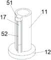
图中:1、外筒;11、定向壁;12、外筒安装块;13、活塞杆;14、活塞块;15、减震孔;16、减震单向阀;17、输液管槽;18、输液孔;2、外筒;21、缸筒;22、内筒安装块;23、密封口;24、进液口;25、进液单向阀;26、吸液口;27、出液孔;28、出液单向阀;29、输液管;3、支撑弹簧;4、伸缩弹簧;41、软管;42、弹性圈;5、伸缩管导向装置;51、连接块;52、导向柱;53、伸缩板;531、厚板;532、薄板;533、导向柱槽;534、软管孔;535弹性圈槽;536、滚轮槽;537、滚轮;538、连接杆;6、发动机液压减震系统;61、支撑板;62、发动机;63、吸热管;64、散热片;65、冷却液箱;7、悬架液压减震系统;71、悬架系统;72、变速箱;73、润滑液箱。In the figure: 1, outer cylinder; 11, directional wall; 12, outer cylinder mounting block; 13, piston rod; 14, piston block; 15, shock absorption hole; 16, shock absorption check valve; 17, infusion pipe groove; 18. Infusion hole; 2. Outer cylinder; 21. Cylinder cylinder; 22. Inner cylinder mounting block; 23. Sealing port; 24. Liquid inlet; 25. Liquid inlet check valve; 26. Liquid suction port; 27. Outlet Liquid hole; 28. Outlet check valve; 29. Infusion tube; 3. Support spring; 4. Telescopic spring; 41. Hose; 42. Elastic ring; 5. Telescopic tube guide; 51. Connection block; Guide column; 53, telescopic plate; 531, thick plate; 532, thin plate; 533, guide column groove; 534, hose hole; 535 elastic ring groove; 536, roller groove; 537, roller; 538, connecting rod; 6, Engine hydraulic shock absorption system; 61, support plate; 62, engine; 63, heat absorption pipe; 64, heat sink; 65, coolant tank; 7, suspension hydraulic shock absorption system; 71, suspension system; 72, transmission 73. Lubricating fluid tank.
具体实施方式Detailed ways
下面将结合本发明实施例中的附图,对本发明实施例中的技术方案进行清楚、完整地描述,显然,所描述的实施例仅仅是本发明一部分实施例,而不是全部的实施例。基于本发明中的实施例,本领域普通技术人员在没有做出创造性劳动前提下所获得的所有其他实施例,都属于本发明保护的范围。The technical solutions in the embodiments of the present invention will be clearly and completely described below with reference to the accompanying drawings in the embodiments of the present invention. Obviously, the described embodiments are only a part of the embodiments of the present invention, but not all of the embodiments. Based on the embodiments of the present invention, all other embodiments obtained by those of ordinary skill in the art without creative efforts shall fall within the protection scope of the present invention.
请参阅图1-6,本发明提供技术方案:如图1,一种液压减震结构,包括外筒1和内筒2,外筒1包括定向壁11,定向壁11一端连接有外筒安装块12,外筒安装块12中间安装有活塞杆13,活塞杆13顶端连接有活塞块14,活塞块14上设置有多个减震孔15,减震孔15内分别安装有减震单向阀16内筒2包括缸筒21,缸筒21一端连接有内筒安装块22,缸筒21另一端设置有密封口23,定向壁11内壁和缸筒21外壁为配合结构,密封口23和活塞杆13为配合结构,缸筒21内壁和活塞块14为配合结构,外筒安装块12和内筒安装块22之间安装有支撑弹簧3,外筒安装块12和内筒安装块22用于将该液压减震结构安装到液压减震系统中,当未受到振动时,支撑弹簧3起到支撑外部结构的作用,受到振动时,外筒1和内筒2收缩,活塞杆13推动活塞块14向上运动,挤压缸筒21内的液体,此时进液单向阀25和出液单向阀28均为闭合,减震单向阀16为开启,缸筒21上层液体穿过减震孔15流到缸筒21下方,在此过程中,液体和减震孔15的摩擦起到了减震的作用;Please refer to FIGS. 1-6, the present invention provides technical solutions: as shown in FIG. 1, a hydraulic shock absorption structure includes an
如图1,缸筒21上端设置有多个进液孔24,进液孔24内分别安装有进液单向阀25,进液孔24顶部互相连通,内筒安装块22一侧设置有吸液口26,吸液口26向内延伸至进液孔24顶部,液压减震结构压缩结束后,支撑弹簧3推动外筒1和内筒2展开,此时减震单向阀16为闭合,进液单向阀25为开启,在活塞块14向下运动的同时,可以通过吸液口26从外部往缸筒21上层吸入液体;As shown in FIG. 1 , the upper end of the
如图1和图2,缸筒21下端设置有多个出液孔27,出液孔27内分别安装有出液单向阀28,出液孔27底部互相连通,出液孔27底部连接有输液管29,定向壁11一侧设置有输液管槽17,输液管29通过输液管槽17伸出定向壁11后向下弯曲,在活塞块14向下运动时,减震单向阀16为闭合,出液单向阀28为开启,活塞块14可以将缸筒21下层的液体推出至输液管29,使该液压减震结构在减震的同时可以进行液体的输送;1 and 2, a plurality of liquid outlet holes 27 are provided at the lower end of the
如图1和图3,外筒安装块12一侧设置有输液孔18,输液孔18和输液管29之间安装有伸缩管4,伸缩管4包括软管41,软管41上端与输液管29相连,软管41下端与输液孔18相连,软管41外侧连接有若干弹性圈42,若直接从输液管29进行液体的输送,水管需穿过支撑弹簧3与输液管29相连,液压减震结构压缩时,支撑弹簧3会挤压损坏水管,因此,通过软管41将液体输送至输液孔18进行排出,可以避免水管被支撑弹簧3夹坏;1 and 3, an
如图1和图2,伸缩管4外套有伸缩管导向装置5,伸缩管导向装置5包括连接块51,连接块51安装于输液管槽17上方,连接块51和外筒安装块12之间安装有多个导向柱52,导向柱52上安装有多个伸缩板53,通过导向柱52和伸缩板53可以保证软管41在液压减震结构收缩时也进行收缩,防止软管41在液压减震结构收缩时弯曲,被支撑弹簧3夹住;1 and 2, the
如图4,伸缩板53包括厚板531,厚板531中间连接有薄板532,厚板上设置有多个导向柱槽533,导向柱槽533和导向柱52为配合结构,薄板532中间设置有软管孔534,软管孔534内侧设置有弹性圈槽535,弹性圈槽535和弹性圈42为配合结构,通过导向柱槽533和导向柱52的配合,使伸缩板53只能沿着导向柱52上下移动,弹性圈42卡在弹性圈槽535内,使伸缩板53和伸缩管4相连,伸缩管4会和伸缩板53一起运动;4, the
如图4,厚板531内侧设置有多个滚轮槽536,滚轮槽536内分别安装有滚轮537,上下两个厚板531的滚轮537之间交错连接有连接杆538,同一侧的两个连接杆538旋转轴相连,液压减震结构伸长时,第一个伸缩板53被拉动时,第一和第二个伸缩板53间的滚轮537会向滚动厚板531中间滚动,使连接杆538变为X形,上下两个伸缩板53分开,同时带动内侧的伸缩管4伸长,当滚轮537滚到滚轮槽536末端时,第二个伸缩板53会被拉起,接下来的伸缩板53重复上述过程达到拉伸伸缩管4的效果,反之液压减震结构压缩时,连接杆538会由X形便会原状,使伸缩管4和伸缩板53一起收缩。As shown in FIG. 4 , a plurality of
如图5,液压减震结构的外部设置有发动机液压减震系统6,发动机液压减震系统包括支撑板61,内筒安装块22与支撑板61底部相连,支撑板61上安装有发动机62,发动机62外缠绕有吸热管63,吸热管63一端通过水管与输液孔18相连,吸热管63另一端通过水管连接有散热片64,散热片64通过水管连接有冷却液箱65,冷却液箱65下端通过水管与吸液口26相连,发动机62振动时,液压减震结构会使用冷却液箱65内的冷却液进行减震,同时将冷却液输送至吸热管63吸收发动机62的热量,之后顺着水管流向散热片64将热量散发,最后回到冷却液箱65,形成循环,达到在减震发动机62的同时,对发动机62进行冷却的效果,并且发动机62工作越剧烈,振动也越大,冷却液的输送速度也能随之增大,使冷却速度自动适应发动机62工作状况;As shown in FIG. 5 , an engine hydraulic damping
如图6,液压减震结构的外部设置有悬架液压减震系统7,悬架液压减震系统7包括悬架71,外筒安装块12分别与悬架系统71相连,悬架液压减震系统7还包括变速箱72,输液孔18分别通过水管与变速箱72上端相连,变速箱72底端通过水管连接有润滑液箱73,润滑液箱73底端通过水管与吸液口26相连,汽车在行驶时,悬架71的震动被液压减震结构吸收,液压减震结构吸收润滑液箱73中的润滑液进行减震,同时将润滑液输送至变速箱72上方,润滑液从上方落到变速器上,进行润滑,多余的润滑液则落到变速箱72下端,然后流入润滑液箱73内,达到在减震悬架71的同时,对变速器进行润滑的效果。As shown in FIG. 6 , a suspension hydraulic
工作原理:外筒安装块12和内筒安装块22用于将该液压减震结构安装到液压减震系统中,当未受到振动时,支撑弹簧3起到支撑外部结构的作用,受到振动时,外筒1和内筒2收缩,活塞杆13推动活塞块14向上运动,挤压缸筒21内的液体,此时进液单向阀25和出液单向阀28均为闭合,减震单向阀16为开启,缸筒21上层液体穿过减震孔15流到缸筒21下方,在此过程中,液体和减震孔15的摩擦起到了减震的作用,液压减震结构压缩结束后,支撑弹簧3推动外筒1和内筒2展开,此时减震单向阀16为闭合,进液单向阀25为开启,在活塞块14向下运动的同时,可以通过吸液口26从外部往缸筒21上层吸入液体,在活塞块14向下运动时,减震单向阀16为闭合,出液单向阀28为开启,活塞块14可以将缸筒21下层的液体推出至输液管29,使该液压减震结构在减震的同时可以进行液体的输送,若直接从输液管29进行液体的输送,水管需穿过支撑弹簧3与输液管29相连,液压减震结构压缩时,支撑弹簧3会挤压损坏水管,因此,通过软管41将液体输送至输液孔18进行排出,可以避免水管被支撑弹簧3夹坏,通过导向柱52和伸缩板53可以保证软管41在液压减震结构收缩时也进行收缩,防止软管41在液压减震结构收缩时弯曲,被支撑弹簧3夹住,通过导向柱槽533和导向柱52的配合,使伸缩板53只能沿着导向柱52上下移动,弹性圈42卡在弹性圈槽535内,使伸缩板53和伸缩管4相连,伸缩管4会和伸缩板53一起运动,液压减震结构伸长时,第一个伸缩板53被拉动时,第一和第二个伸缩板53间的滚轮537会向滚动厚板531中间滚动,使连接杆538变为X形,上下两个伸缩板53分开,同时带动内侧的伸缩管4伸长,当滚轮537滚到滚轮槽536末端时,第二个伸缩板53会被拉起,接下来的伸缩板53重复上述过程达到拉伸伸缩管4的效果,反之液压减震结构压缩时,连接杆538会由X形便会原状,使伸缩管4和伸缩板53一起收缩,发动机62振动时,液压减震结构会使用冷却液箱65内的冷却液进行减震,同时将冷却液输送至吸热管63吸收发动机62的热量,之后顺着水管流向散热片64将热量散发,最后回到冷却液箱65,形成循环,达到在减震发动机62的同时,对发动机62进行冷却的效果,并且发动机62工作越剧烈,振动也越大,冷却液的输送速度也能随之增大,使冷却速度自动适应发动机62工作状况,汽车在行驶时,悬架71的震动被液压减震结构吸收,液压减震结构吸收润滑液箱73中的润滑液进行减震,同时将润滑液输送至变速箱72上方,润滑液从上方落到变速器上,进行润滑,多余的润滑液则落到变速箱72下端,然后流入润滑液箱73内,达到在减震悬架71的同时,对变速器进行润滑的效果。Working principle: The outer
需要说明的是,在本文中,诸如第一和第二等之类的关系术语仅仅用来将一个实体或者操作与另一个实体或操作区分开来,而不一定要求或者暗示这些实体或操作之间存在任何这种实际的关系或者顺序。而且,术语“包括”、“包含”或者其任何其他变体意在涵盖非排他性的包含,从而使得包括一系列要素的过程、方法、物品或者设备不仅包括那些要素,而且还包括没有明确列出的其他要素,或者是还包括为这种过程、方法、物品或者设备所固有的要素。It should be noted that, in this document, relational terms such as first and second are only used to distinguish one entity or operation from another entity or operation, and do not necessarily require or imply any relationship between these entities or operations. any such actual relationship or sequence exists. Moreover, the terms "comprising", "comprising" or any other variation thereof are intended to encompass a non-exclusive inclusion such that a process, method, article or device that includes a list of elements includes not only those elements, but also includes not explicitly listed or other elements inherent to such a process, method, article or apparatus.
最后应说明的是:以上所述仅为本发明的优选实施例而已,并不用于限制本发明,尽管参照前述实施例对本发明进行了详细的说明,对于本领域的技术人员来说,其依然可以对前述各实施例所记载的技术方案进行修改,或者对其中部分技术特征进行等同替换。凡在本发明的精神和原则之内,所作的任何修改、等同替换、改进等,均应包含在本发明的保护范围之内。Finally, it should be noted that the above descriptions are only preferred embodiments of the present invention, and are not intended to limit the present invention. Although the present invention has been described in detail with reference to the foregoing embodiments, for those skilled in the art, the The technical solutions described in the foregoing embodiments may be modified, or some technical features thereof may be equivalently replaced. Any modification, equivalent replacement, improvement, etc. made within the spirit and principle of the present invention shall be included within the protection scope of the present invention.
Claims (9)
Translated fromChinesePriority Applications (1)
| Application Number | Priority Date | Filing Date | Title |
|---|---|---|---|
| CN202010786279.6ACN112128301B (en) | 2020-08-07 | 2020-08-07 | Hydraulic shock-absorbing structure |
Applications Claiming Priority (1)
| Application Number | Priority Date | Filing Date | Title |
|---|---|---|---|
| CN202010786279.6ACN112128301B (en) | 2020-08-07 | 2020-08-07 | Hydraulic shock-absorbing structure |
Publications (2)
| Publication Number | Publication Date |
|---|---|
| CN112128301Atrue CN112128301A (en) | 2020-12-25 |
| CN112128301B CN112128301B (en) | 2021-11-30 |
Family
ID=73850957
Family Applications (1)
| Application Number | Title | Priority Date | Filing Date |
|---|---|---|---|
| CN202010786279.6AActiveCN112128301B (en) | 2020-08-07 | 2020-08-07 | Hydraulic shock-absorbing structure |
Country Status (1)
| Country | Link |
|---|---|
| CN (1) | CN112128301B (en) |
Cited By (3)
| Publication number | Priority date | Publication date | Assignee | Title |
|---|---|---|---|---|
| CN113055283A (en)* | 2021-04-21 | 2021-06-29 | 莆田学院 | Internet of things gateway device convenient to overhaul and maintain |
| CN115013474A (en)* | 2022-08-08 | 2022-09-06 | 常州市中昊轨道交通科技发展有限公司 | Long-life buffering and damping piece for motor train unit and machining method thereof |
| CN118066260A (en)* | 2024-04-18 | 2024-05-24 | 泰兴市康森爱特传动设备科技有限公司 | A planetary gear reducer |
Citations (8)
| Publication number | Priority date | Publication date | Assignee | Title |
|---|---|---|---|---|
| US5628703A (en)* | 1995-01-20 | 1997-05-13 | Ford Motor Company | Flywheel/clutch arrangement for manual-shift synchronized change-speed gearboxes |
| CN2799298Y (en)* | 2004-02-19 | 2006-07-26 | 郭川 | Pressure-controlled damp changeable shock absorber |
| CN102913587A (en)* | 2012-10-25 | 2013-02-06 | 中国民航大学 | Magneto-rheological damper |
| CN106715229A (en)* | 2014-09-19 | 2017-05-24 | Kyb株式会社 | Railroad vibration control device |
| CN110017349A (en)* | 2019-03-15 | 2019-07-16 | 江苏大学 | A kind of automobile-used rigidity controllable magnetic rheology damper and rigidity regulate and control method |
| CN209483850U (en)* | 2019-01-08 | 2019-10-11 | 金华凯凯壹科技有限公司 | An easily adjustable shock absorber for a motorcycle |
| CN111316387A (en)* | 2017-11-17 | 2020-06-19 | Kyb株式会社 | Control device and vibration damping device for railway vehicle |
| CN210942100U (en)* | 2019-06-19 | 2020-07-07 | 界首市路虎车业有限公司 | Novel electric motor car rear wheel shock attenuation device |
- 2020
- 2020-08-07CNCN202010786279.6Apatent/CN112128301B/enactiveActive
Patent Citations (8)
| Publication number | Priority date | Publication date | Assignee | Title |
|---|---|---|---|---|
| US5628703A (en)* | 1995-01-20 | 1997-05-13 | Ford Motor Company | Flywheel/clutch arrangement for manual-shift synchronized change-speed gearboxes |
| CN2799298Y (en)* | 2004-02-19 | 2006-07-26 | 郭川 | Pressure-controlled damp changeable shock absorber |
| CN102913587A (en)* | 2012-10-25 | 2013-02-06 | 中国民航大学 | Magneto-rheological damper |
| CN106715229A (en)* | 2014-09-19 | 2017-05-24 | Kyb株式会社 | Railroad vibration control device |
| CN111316387A (en)* | 2017-11-17 | 2020-06-19 | Kyb株式会社 | Control device and vibration damping device for railway vehicle |
| CN209483850U (en)* | 2019-01-08 | 2019-10-11 | 金华凯凯壹科技有限公司 | An easily adjustable shock absorber for a motorcycle |
| CN110017349A (en)* | 2019-03-15 | 2019-07-16 | 江苏大学 | A kind of automobile-used rigidity controllable magnetic rheology damper and rigidity regulate and control method |
| CN210942100U (en)* | 2019-06-19 | 2020-07-07 | 界首市路虎车业有限公司 | Novel electric motor car rear wheel shock attenuation device |
Cited By (5)
| Publication number | Priority date | Publication date | Assignee | Title |
|---|---|---|---|---|
| CN113055283A (en)* | 2021-04-21 | 2021-06-29 | 莆田学院 | Internet of things gateway device convenient to overhaul and maintain |
| CN113055283B (en)* | 2021-04-21 | 2022-06-21 | 莆田学院 | An IoT gateway device that is easy to repair and maintain |
| CN115013474A (en)* | 2022-08-08 | 2022-09-06 | 常州市中昊轨道交通科技发展有限公司 | Long-life buffering and damping piece for motor train unit and machining method thereof |
| CN115013474B (en)* | 2022-08-08 | 2022-11-04 | 常州市中昊轨道交通科技发展有限公司 | Long-life buffering and damping piece for motor train unit and machining method thereof |
| CN118066260A (en)* | 2024-04-18 | 2024-05-24 | 泰兴市康森爱特传动设备科技有限公司 | A planetary gear reducer |
Also Published As
| Publication number | Publication date |
|---|---|
| CN112128301B (en) | 2021-11-30 |
Similar Documents
| Publication | Publication Date | Title |
|---|---|---|
| CN112128301A (en) | A hydraulic shock absorber | |
| CN104044429B (en) | Hydraulic interconnection ISD (Inerter-Spring-Damper) hanger bracket | |
| CN209913648U (en) | A practical anti-vibration motor shaft | |
| CN102913585A (en) | Hydro-pneumatic spring | |
| WO2015127800A1 (en) | Hydraulic damping device | |
| CN104018814A (en) | Double-balanced range-extended hydraulic oil pumping unit | |
| CN111015309A (en) | A kind of inner pneumatic support tool for cylindrical parts | |
| CN213332179U (en) | Stable hydraulic buffer | |
| CN115807751A (en) | Closed hydraulic drive double-acting efficient hydraulic pressure boosting water injection equipment | |
| CN220337354U (en) | Compound adjustable double-cylinder hydraulic shock absorber | |
| CN104864022B (en) | An energy recovery device for a shock absorber | |
| CN104934191B (en) | It is removably connected with inner fin and the transformer radiator of telescopic outer fin | |
| CN209444532U (en) | An air compressor with good cooling effect | |
| CN217604446U (en) | A shock-absorbing U-bend oil return pipe | |
| CN108050035B (en) | A kind of automobile electronic cooling water pump | |
| CN104916398B (en) | It is connected with inner fin and the transformer radiator of the outer fin of extension type | |
| CN207145509U (en) | Shock absorber and there is its vehicle | |
| CN209483746U (en) | Forced cooling device for shield machine | |
| CN209370352U (en) | A hydraulic shock absorber for electric vehicles with circulating heat dissipation | |
| CN219139526U (en) | Hydraulic cylinder heat sink | |
| CN202349082U (en) | Double-cylinder type shock absorber capable of recovering vibration energy | |
| CN221278332U (en) | Piston rod for shock absorber | |
| CN115574040B (en) | Cooling system for electric vehicle | |
| CN217271612U (en) | Potential energy utilization device for shock absorber | |
| CN105952722B (en) | The method of work of the hydraulic pressure heat-exchanger rig of hydraulic pressure bypass with piston type relief valve |
Legal Events
| Date | Code | Title | Description |
|---|---|---|---|
| PB01 | Publication | ||
| PB01 | Publication | ||
| SE01 | Entry into force of request for substantive examination | ||
| SE01 | Entry into force of request for substantive examination | ||
| GR01 | Patent grant | ||
| GR01 | Patent grant | ||
| TR01 | Transfer of patent right | ||
| TR01 | Transfer of patent right | Effective date of registration:20240812 Address after:230000 Room 203, building 2, phase I, e-commerce Park, Jinggang Road, Shushan Economic Development Zone, Hefei City, Anhui Province Patentee after:Hefei Jiuzhou Longteng scientific and technological achievement transformation Co.,Ltd. Country or region after:China Address before:224000 No. 1 Hope Avenue Middle Road, Tinghu District, Yancheng City, Jiangsu Province Patentee before:YANCHENG INSTITUTE OF TECHNOLOGY Country or region before:China |