CN112128191A - Decorative clip with four-point retention - Google Patents
Decorative clip with four-point retentionDownload PDFInfo
- Publication number
- CN112128191A CN112128191ACN202010579757.6ACN202010579757ACN112128191ACN 112128191 ACN112128191 ACN 112128191ACN 202010579757 ACN202010579757 ACN 202010579757ACN 112128191 ACN112128191 ACN 112128191A
- Authority
- CN
- China
- Prior art keywords
- fastener
- grommet
- pin
- plate
- flange
- Prior art date
- Legal status (The legal status is an assumption and is not a legal conclusion. Google has not performed a legal analysis and makes no representation as to the accuracy of the status listed.)
- Granted
Links
Images


Classifications
- F—MECHANICAL ENGINEERING; LIGHTING; HEATING; WEAPONS; BLASTING
- F16—ENGINEERING ELEMENTS AND UNITS; GENERAL MEASURES FOR PRODUCING AND MAINTAINING EFFECTIVE FUNCTIONING OF MACHINES OR INSTALLATIONS; THERMAL INSULATION IN GENERAL
- F16B—DEVICES FOR FASTENING OR SECURING CONSTRUCTIONAL ELEMENTS OR MACHINE PARTS TOGETHER, e.g. NAILS, BOLTS, CIRCLIPS, CLAMPS, CLIPS OR WEDGES; JOINTS OR JOINTING
- F16B21/00—Means for preventing relative axial movement of a pin, spigot, shaft or the like and a member surrounding it; Stud-and-socket releasable fastenings
- F16B21/06—Releasable fastening devices with snap-action
- F16B21/07—Releasable fastening devices with snap-action in which the socket has a resilient part
- F16B21/073—Releasable fastening devices with snap-action in which the socket has a resilient part the socket having a resilient part on its inside
- F16B21/075—Releasable fastening devices with snap-action in which the socket has a resilient part the socket having a resilient part on its inside the socket having resilient parts on its inside and outside
- F—MECHANICAL ENGINEERING; LIGHTING; HEATING; WEAPONS; BLASTING
- F16—ENGINEERING ELEMENTS AND UNITS; GENERAL MEASURES FOR PRODUCING AND MAINTAINING EFFECTIVE FUNCTIONING OF MACHINES OR INSTALLATIONS; THERMAL INSULATION IN GENERAL
- F16B—DEVICES FOR FASTENING OR SECURING CONSTRUCTIONAL ELEMENTS OR MACHINE PARTS TOGETHER, e.g. NAILS, BOLTS, CIRCLIPS, CLAMPS, CLIPS OR WEDGES; JOINTS OR JOINTING
- F16B21/00—Means for preventing relative axial movement of a pin, spigot, shaft or the like and a member surrounding it; Stud-and-socket releasable fastenings
- F16B21/06—Releasable fastening devices with snap-action
- F16B21/07—Releasable fastening devices with snap-action in which the socket has a resilient part
- F16B21/073—Releasable fastening devices with snap-action in which the socket has a resilient part the socket having a resilient part on its inside
- F—MECHANICAL ENGINEERING; LIGHTING; HEATING; WEAPONS; BLASTING
- F16—ENGINEERING ELEMENTS AND UNITS; GENERAL MEASURES FOR PRODUCING AND MAINTAINING EFFECTIVE FUNCTIONING OF MACHINES OR INSTALLATIONS; THERMAL INSULATION IN GENERAL
- F16B—DEVICES FOR FASTENING OR SECURING CONSTRUCTIONAL ELEMENTS OR MACHINE PARTS TOGETHER, e.g. NAILS, BOLTS, CIRCLIPS, CLAMPS, CLIPS OR WEDGES; JOINTS OR JOINTING
- F16B13/00—Dowels or other devices fastened in walls or the like by inserting them in holes made therein for that purpose
- F16B13/04—Dowels or other devices fastened in walls or the like by inserting them in holes made therein for that purpose with parts gripping in the hole or behind the reverse side of the wall after inserting from the front
- F16B13/08—Dowels or other devices fastened in walls or the like by inserting them in holes made therein for that purpose with parts gripping in the hole or behind the reverse side of the wall after inserting from the front with separate or non-separate gripping parts moved into their final position in relation to the body of the device without further manual operation
- F16B13/0891—Dowels or other devices fastened in walls or the like by inserting them in holes made therein for that purpose with parts gripping in the hole or behind the reverse side of the wall after inserting from the front with separate or non-separate gripping parts moved into their final position in relation to the body of the device without further manual operation with a locking element, e.g. wedge, key or ball moving along an inclined surface of the dowel body
- F—MECHANICAL ENGINEERING; LIGHTING; HEATING; WEAPONS; BLASTING
- F16—ENGINEERING ELEMENTS AND UNITS; GENERAL MEASURES FOR PRODUCING AND MAINTAINING EFFECTIVE FUNCTIONING OF MACHINES OR INSTALLATIONS; THERMAL INSULATION IN GENERAL
- F16B—DEVICES FOR FASTENING OR SECURING CONSTRUCTIONAL ELEMENTS OR MACHINE PARTS TOGETHER, e.g. NAILS, BOLTS, CIRCLIPS, CLAMPS, CLIPS OR WEDGES; JOINTS OR JOINTING
- F16B21/00—Means for preventing relative axial movement of a pin, spigot, shaft or the like and a member surrounding it; Stud-and-socket releasable fastenings
- F16B21/09—Releasable fastening devices with a stud engaging a keyhole slot
- F—MECHANICAL ENGINEERING; LIGHTING; HEATING; WEAPONS; BLASTING
- F16—ENGINEERING ELEMENTS AND UNITS; GENERAL MEASURES FOR PRODUCING AND MAINTAINING EFFECTIVE FUNCTIONING OF MACHINES OR INSTALLATIONS; THERMAL INSULATION IN GENERAL
- F16B—DEVICES FOR FASTENING OR SECURING CONSTRUCTIONAL ELEMENTS OR MACHINE PARTS TOGETHER, e.g. NAILS, BOLTS, CIRCLIPS, CLAMPS, CLIPS OR WEDGES; JOINTS OR JOINTING
- F16B5/00—Joining sheets or plates, e.g. panels, to one another or to strips or bars parallel to them
- F16B5/06—Joining sheets or plates, e.g. panels, to one another or to strips or bars parallel to them by means of clamps or clips
- F16B5/0607—Joining sheets or plates, e.g. panels, to one another or to strips or bars parallel to them by means of clamps or clips joining sheets or plates to each other
- F16B5/0621—Joining sheets or plates, e.g. panels, to one another or to strips or bars parallel to them by means of clamps or clips joining sheets or plates to each other in parallel relationship
- F16B5/0664—Joining sheets or plates, e.g. panels, to one another or to strips or bars parallel to them by means of clamps or clips joining sheets or plates to each other in parallel relationship at least one of the sheets or plates having integrally formed or integrally connected snap-in-features
- B—PERFORMING OPERATIONS; TRANSPORTING
- B60—VEHICLES IN GENERAL
- B60R—VEHICLES, VEHICLE FITTINGS, OR VEHICLE PARTS, NOT OTHERWISE PROVIDED FOR
- B60R13/00—Elements for body-finishing, identifying, or decorating; Arrangements or adaptations for advertising purposes
- B60R13/02—Internal Trim mouldings ; Internal Ledges; Wall liners for passenger compartments; Roof liners
- B60R13/0206—Arrangements of fasteners and clips specially adapted for attaching inner vehicle liners or mouldings
- F—MECHANICAL ENGINEERING; LIGHTING; HEATING; WEAPONS; BLASTING
- F16—ENGINEERING ELEMENTS AND UNITS; GENERAL MEASURES FOR PRODUCING AND MAINTAINING EFFECTIVE FUNCTIONING OF MACHINES OR INSTALLATIONS; THERMAL INSULATION IN GENERAL
- F16B—DEVICES FOR FASTENING OR SECURING CONSTRUCTIONAL ELEMENTS OR MACHINE PARTS TOGETHER, e.g. NAILS, BOLTS, CIRCLIPS, CLAMPS, CLIPS OR WEDGES; JOINTS OR JOINTING
- F16B21/00—Means for preventing relative axial movement of a pin, spigot, shaft or the like and a member surrounding it; Stud-and-socket releasable fastenings
- F16B21/06—Releasable fastening devices with snap-action
- F16B21/065—Releasable fastening devices with snap-action with an additional locking element
- F—MECHANICAL ENGINEERING; LIGHTING; HEATING; WEAPONS; BLASTING
- F16—ENGINEERING ELEMENTS AND UNITS; GENERAL MEASURES FOR PRODUCING AND MAINTAINING EFFECTIVE FUNCTIONING OF MACHINES OR INSTALLATIONS; THERMAL INSULATION IN GENERAL
- F16B—DEVICES FOR FASTENING OR SECURING CONSTRUCTIONAL ELEMENTS OR MACHINE PARTS TOGETHER, e.g. NAILS, BOLTS, CIRCLIPS, CLAMPS, CLIPS OR WEDGES; JOINTS OR JOINTING
- F16B21/00—Means for preventing relative axial movement of a pin, spigot, shaft or the like and a member surrounding it; Stud-and-socket releasable fastenings
- F16B21/10—Means for preventing relative axial movement of a pin, spigot, shaft or the like and a member surrounding it; Stud-and-socket releasable fastenings by separate parts
- F16B21/12—Means for preventing relative axial movement of a pin, spigot, shaft or the like and a member surrounding it; Stud-and-socket releasable fastenings by separate parts with locking-pins or split-pins thrust into holes
- F16B21/125—Means for preventing relative axial movement of a pin, spigot, shaft or the like and a member surrounding it; Stud-and-socket releasable fastenings by separate parts with locking-pins or split-pins thrust into holes radially resilient or with a snap-action member, e.g. elastic tooth, pawl with spring, resilient coil or wire
- F—MECHANICAL ENGINEERING; LIGHTING; HEATING; WEAPONS; BLASTING
- F16—ENGINEERING ELEMENTS AND UNITS; GENERAL MEASURES FOR PRODUCING AND MAINTAINING EFFECTIVE FUNCTIONING OF MACHINES OR INSTALLATIONS; THERMAL INSULATION IN GENERAL
- F16B—DEVICES FOR FASTENING OR SECURING CONSTRUCTIONAL ELEMENTS OR MACHINE PARTS TOGETHER, e.g. NAILS, BOLTS, CIRCLIPS, CLAMPS, CLIPS OR WEDGES; JOINTS OR JOINTING
- F16B5/00—Joining sheets or plates, e.g. panels, to one another or to strips or bars parallel to them
- F16B5/06—Joining sheets or plates, e.g. panels, to one another or to strips or bars parallel to them by means of clamps or clips
- F16B5/0607—Joining sheets or plates, e.g. panels, to one another or to strips or bars parallel to them by means of clamps or clips joining sheets or plates to each other
- F16B5/0621—Joining sheets or plates, e.g. panels, to one another or to strips or bars parallel to them by means of clamps or clips joining sheets or plates to each other in parallel relationship
- F16B5/0657—Joining sheets or plates, e.g. panels, to one another or to strips or bars parallel to them by means of clamps or clips joining sheets or plates to each other in parallel relationship at least one of the plates providing a raised structure, e.g. of the doghouse type, for connection with the clamps or clips of the other plate
Landscapes
- Engineering & Computer Science (AREA)
- General Engineering & Computer Science (AREA)
- Mechanical Engineering (AREA)
- Insertion Pins And Rivets (AREA)
Abstract
Description
Translated fromChinese相关申请Related applications
本申请要求于2019年6月24日提交的美国临时申请序列号62/865,391的优先权,该申请通过援引以其全部内容并入本文。This application claims priority to US Provisional Application Serial No. 62/865,391, filed June 24, 2019, which is incorporated herein by reference in its entirety.
技术领域technical field
本公开的实施例总体上涉及紧固件,更具体地涉及一种具有四点固位的装饰夹。Embodiments of the present disclosure relate generally to fasteners, and more particularly to a trim clip with four-point retention.
背景技术Background technique
近年来,已经开发出用于将多个面板彼此固定的紧固件。例如,车辆包括经由紧固件附接至车身面板的内部面板,该紧固件穿过面板中的相应狭槽插入。这些紧固件允许将面板快速组装在一起。In recent years, fasteners have been developed for securing multiple panels to each other. For example, a vehicle includes an interior panel attached to a body panel via fasteners inserted through corresponding slots in the panel. These fasteners allow the panels to be quickly assembled together.
某些已知的紧固件使用具有两个固位点的索环、以及对应的销。在一些情况下,索环附接至车身面板,并且销穿过内部面板插入并被索环所接纳(例如,以便将内部部分附接至车门)。然而,已知的索环几乎没有固位冗余度,并且通常难以安装在车身面板中。进一步地,已知的销通常难以安装在索环中,并且在维修(例如,维修电动车窗组件)期间难以从索环中移除。Some known fasteners use grommets with two retention points, and corresponding pins. In some cases, the grommet is attached to the body panel, and the pin is inserted through the interior panel and received by the grommet (eg, to attach the interior portion to the door). However, known grommets have little retention redundancy and are often difficult to install in body panels. Further, known pins are often difficult to install in the grommet and difficult to remove from the grommet during servicing (eg, servicing of power window assemblies).
因此,需要一种紧固件,该紧固件牢固地固位在车身面板中、安装简单、并且允许相对容易地将面板分开。Accordingly, there is a need for a fastener that securely retains in body panels, is simple to install, and allows for relatively easy separation of the panels.
发明内容SUMMARY OF THE INVENTION
在一个方面,示例紧固件包括索环和销。该索环具有一组底部引入特征。该销被构造成可移除地卡扣接合该索环。该销具有引入特征。In one aspect, example fasteners include grommets and pins. The grommet has a set of bottom entry features. The pin is configured to removably snap-engage the grommet. The pin has a lead-in feature.
在另一方面,示例紧固件包括索环和销。该索环具有圆滑的底板。该销具有圆滑的杆,该圆滑的杆被构造成可移除地接合该索环。In another aspect, example fasteners include grommets and pins. The grommet has a sleek base plate. The pin has a sleek stem configured to removably engage the grommet.
在另一方面,示例紧固件包括索环和销。该索环包括顶板、底板、多个锥形叉指部(prong)、以及多个固位指状物。该底板连接至该顶板并具有一组底部引入特征。该多个锥形叉指部弹性可枢转地连接至该底板并朝向该顶板延伸。该多个固位指状物弹性可枢转地连接至该顶板并朝向该底板延伸。该销被构造成可移除地卡扣接合该多个固位指状物。In another aspect, example fasteners include grommets and pins. The grommet includes a top plate, a bottom plate, a plurality of tapered prongs, and a plurality of retention fingers. The bottom plate is connected to the top plate and has a set of bottom lead-in features. The plurality of tapered fingers are resiliently pivotably connected to the bottom plate and extend toward the top plate. The plurality of retention fingers are resiliently pivotably connected to the top plate and extend toward the bottom plate. The pin is configured to removably snap-engage the plurality of retention fingers.
附图说明Description of drawings
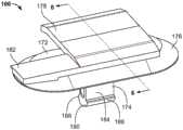
图1是根据本公开的实施例的第一示例紧固件的等距视图;1 is an isometric view of a first example fastener in accordance with embodiments of the present disclosure;
图2是图1的第一示例紧固件的侧视图;FIG. 2 is a side view of the first example fastener of FIG. 1;
图3是图1和图2的第一示例紧固件的仰视图;3 is a bottom view of the first example fastener of FIGS. 1 and 2;
图4是图1、图2和图3的第一示例紧固件的销的等距视图;4 is an isometric view of a pin of the first example fastener of FIGS. 1 , 2 and 3;
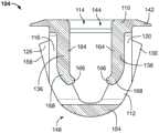
图5是图1、图2和图3的第一示例紧固件的索环的等距视图;5 is an isometric view of a grommet of the first example fastener of FIGS. 1 , 2 and 3;
图6是图4的销沿着图4的剖切线6-6截取的截面视图;6 is a cross-sectional view of the pin of FIG. 4 taken along section line 6-6 of FIG. 4;
图7是图5的索环沿着图5的剖切线7-7截取的截面视图;7 is a cross-sectional view of the grommet of FIG. 5 taken along section line 7-7 of FIG. 5;
图8是图1、图2和图3的第一示例紧固件正被安装到面板中时的等距视图;8 is an isometric view of the first example fastener of FIGS. 1 , 2 and 3 as it is being installed into a panel;
图9是图1、图2、图3和图8的第一示例紧固件已被安装到图8的面板中后的等距视图;Figure 9 is an isometric view of the first example fastener of Figures 1, 2, 3 and 8 after it has been installed into the panel of Figure 8;
图10是已安装到图8和图9的面板中的图1、图2、图3、图8和图9的第一示例紧固件沿着图9的剖切线10-10截取的截面视图;以及10 is a cross-sectional view of the first example fastener of FIGS. 1 , 2 , 3 , 8 and 9 taken along section line 10 - 10 of FIG. 9 installed into the panel of FIGS. 8 and 9 ;as well as
图11是图4和图6的销正从图5和图7的索环中移除同时索环保持安装在图8、图9和图10的面板中的等距视图。11 is an isometric view of the pins of FIGS. 4 and 6 being removed from the grommets of FIGS. 5 and 7 while the grommets remain installed in the panels of FIGS. 8 , 9 and 10 .
在详细说明本披露内容的实施例之前,应理解的是,本公开内容的应用并不局限于以下描述中阐述的或在附图中展示出的部件的构造和布置的细节。本公开内容能够具有其他实施例并且能够以多种不同的方式来实践或实施。而且,应理解的是,在本文中使用的措辞和术语是用于描述的目的,而不应被视为是限制性的。使用“包括”和“包含”及其变化形式旨在涵盖其后所列的项目及其等同形式和额外项目及其等同形式。Before describing embodiments of the present disclosure in detail, it is to be understood that the application of the present disclosure is not limited to the details of construction and the arrangement of components set forth in the following description or illustrated in the accompanying drawings. The present disclosure is capable of other embodiments and of being practiced or carried out in various different ways. Also, it is to be understood that the phraseology and terminology used herein is for the purpose of description and should not be regarded as limiting. The use of "including" and "comprising" and variations thereof is intended to encompass the items listed thereafter and equivalents thereof and additional items and equivalents thereof.
具体实施方式Detailed ways
本公开的实施例提供了一种紧固件,该紧固件牢固地固定到第一面板中、安装简单、并且允许相对容易地将第二面板与第一面板分开。Embodiments of the present disclosure provide a fastener that is securely fastened into the first panel, is simple to install, and allows relatively easy separation of the second panel from the first panel.
在图1、图2、图3、图8、图9和图10中描绘了根据本公开的实施例的第一示例紧固件100。紧固件100包括索环104和销106。A first example fastener 100 according to an embodiment of the present disclosure is depicted in FIGS. 1 , 2 , 3 , 8 , 9 and 10 . Fastener 100 includes grommet 104 and
参考图5,索环104包括顶板110和底板112。顶板110限定了开口114。索环104进一步包括第一连接部116、第二连接部118、第三连接部120、以及第四连接部122。索环104还具有第一叉指部126、第二叉指部128、以及第三叉指部130。参考图3,索环104还包括第四叉指部132。索环104另外包括第一固位指状物136、第二固位指状物138、以及凸缘142。Referring to FIG. 5 , the
参考图5,顶板110与底板112相对。第一连接部116、第二连接部118、第三连接部120、以及第四连接部122将顶板110连接至底板112。第一连接部116和第二连接部118与第三连接部120和第四连接部122相对。Referring to FIG. 5 , the
参考图5,第一叉指部126、第二叉指部128、第三叉指部130、以及第四叉指部132弹性可枢转地连接至底板112并从该底板朝向顶板110延伸。第一叉指部126和第二叉指部128与第三叉指部130和第四叉指部132相对。第一叉指部126、第二叉指部128、第三叉指部130、以及第四叉指部132在第一连接部116、第二连接部118、第三连接部120、以及第四连接部122的外侧。换句话说,第一连接部116、第二连接部118、第三连接部120、以及第四连接部122在第一叉指部126、第二叉指部128、第三叉指部130、以及第四叉指部132之间。Referring to FIG. 5 , the first interdigitated
参考图5,第一固位指状物136和第二固位指状物138弹性可枢转地连接至顶板110并从该顶板朝向底板112延伸。第一固位指状物136与第二固位指状物138相对。第一固位指状物136在第一连接部116和第二连接部118的内侧。第二固位指状物138在第三连接部120和第四连接部122的内侧。换句话说,第一固位指状物136在第一连接部116与第二连接部118之间。进一步地,第二固位指状物138在第三连接部120与第四连接部122之间。Referring to FIG. 5 , the
参考图5,凸缘142连接至顶板110并从该顶板向外延伸。凸缘142大致垂直于第一连接部116、第二连接部118、第三连接部120、第四连接部122、第一固位指状物136、以及第二固位指状物138。凸缘142大致平行于顶板110和底板112。Referring to Figure 5,
参考图5,顶板110具有一组顶部引入特征144。该组顶部引入特征144可以包括任何类型的引入特征(例如,倒角、半径部、斜坡等)。该组顶部引入特征144在开口114周围并至少部分地限定了该开口。Referring to FIG. 5 , the
参考图2,底板112包括一组底部引入特征148。该组底部引入特征可以包括任何类型的引入特征。在图2所示的示例中,该组底部引入特征148包括第一倒角150、第二倒角152、以及横向半径部154。横向半径部154在第一倒角150与第二倒角152之间。换句话说,底板112经由该组底部引入特征148而具有圆滑部。Referring to FIG. 2 , the
参考图8,第一叉指部126、第二叉指部128、第三叉指部130、以及第四叉指部132中的每一个(图3中示出)具有斜坡158和顶端160。斜坡158的宽度从底板112至顶端160逐渐变宽。换句话说,斜坡158是锥形的,由此相比于顶端160在更靠近底板112的位置更窄。Referring to FIG. 8 , each of the first interdigitated
参考图7,第一固位指状物136和第二固位指状物138中的每一个包括弹性部分164和卡止部166。弹性部分164弹性可枢转地连接至顶板110并从该顶板大致垂直地延伸。弹性部分164与第一连接部116、第二连接部118、第三连接部120、以及第四连接部122大致平行。卡止部166从弹性部分164倾斜地向内延伸。在一些实施例中,卡止部166是圆滑的。卡止部166限定了外部肩部168。Referring to FIG. 7 , each of the
参考图6,销106包括板172、插入部174、凸缘176、以及连接部分178。在一些实施例中,销106还包括密封件(未示出)。插入部174连接至板172并从该板大致垂直地延伸。凸缘176弹性地连接至板172上并从该板沿倾斜地向外延伸。参考图4,在一些实施例中,凸缘176围绕板172。进一步地,在一些实施例中,密封件接合并围绕凸缘176。在一些实施例中,密封件由弹性体形成。连接部分178连接至板172并从该板大致垂直地延伸。因此,板172在连接部分178与插入部174之间。在一些实施例中,连接部分178包括侧向延伸的固位倒钩182。Referring to FIG. 6 , the
参考图6,插入部174包括杆184、第一倒钩186、以及第二倒钩188。杆184还包括引入特征190。更具体地,杆184在引入特征190终止。引入特征190可以是任何类型的引入特征。在图6的示例中,引入特征190是半径部。因此,在一些实施例中,杆184由于引入特征190而具有圆滑部。杆184连接至板172并从该板延伸。第一倒钩186和第二倒钩188从杆184向外延伸。引入特征190在第一倒钩186与第二倒钩188之间并过渡地连接至该第一倒钩和第二倒钩。在一些实施例中,第一倒钩186和第二倒钩188是圆滑的。参考图10,第一倒钩186和第二倒钩188被成形为与卡止部166配合地接合。Referring to FIG. 6 , the
参考图10,当组装紧固件100时,将销106插入到索环104中。随着将销106插入到索环104中,该组顶部引入特征144和引入特征190一起工作,以引导杆184进入并穿过开口114。随着将销106进一步插入到索环104中,第一倒钩186和第二倒钩188碰到卡止部166。随着第一倒钩186和第二倒钩188推压卡止部166,第一固位指状物136和第二固位指状物138弹性地向外枢转。当第一倒钩186和第二倒钩188被推过卡止部166时,第一固位指状物136和第二固位指状物138弹性地向内枢转,以分别接合第一倒钩186和第二倒钩188。因此,销106与索环104卡扣接合。进一步地,当销106被组装到索环104中时,板172接合顶板110。另外,销106的凸缘176接合索环104的凸缘142。销106的凸缘176和索环的凸缘142的形状彼此配合地接合。Referring to FIG. 10 , when the
参考图8,在操作中,在一些情况下,将组装好的紧固件100引入到限定在面板196中的狭槽194中,如箭头198所指示的。在一些情况下,可以在销106没有被组装到索环104中的情况下将索环104引入到狭槽194中。当将紧固件100引入到面板196中时,该组底部引入特征148引导索环104进入狭槽194。随着将紧固件100进一步推入面板196中,斜坡158引导紧固件100进入狭槽194。随着将紧固件100进一步插入到面板196中,第一叉指部126、第二叉指部128、第三叉指部130、以及第四叉指部132(图3中示出)弹性地向内枢转。参考图9,当第一叉指部126、第二叉指部128、第三叉指部130、以及第四叉指部132被推过狭槽194时,第一叉指部126、第二叉指部128、第三叉指部130、以及第四叉指部132弹性地向外枢转。因此,紧固件100与面板196卡扣接合。Referring to FIG. 8 , in operation, in some cases, the assembled
参考图10,当紧固件100被安装到面板196中时,顶端160接合面板196的底表面200。另外,当紧固件100被安装到面板196中时,凸缘176接合面板196的顶表面202。因此,因为凸缘176与板172弹性可枢转地接合,所以凸缘176背离顶表面202推动销106,以拉动第一倒钩186和第二倒钩188使之紧紧抵靠卡止部166,并拉动顶端160使之抵靠底表面200。另外,凸缘176提供深度保护,以防止销106被完全推过面板196。Referring to FIG. 10 , the
参考图11,进一步在操作中,可以将销106从索环104中抽出,如箭头204所指示的。当背离索环104拉动销106时,第一倒钩186和第二倒钩188碰到卡止部166。另外,随着销106被拉动,顶端160接合底表面200。随着销106进一步被拉动,第一倒钩186和第二倒钩188推压卡止部166,以使第一固位指状物136和第二固位指状物138分别向外枢转。应了解的是,顶端160抵靠底表面200的接合为第一倒钩186和第二倒钩188推压卡止部166提供了反作用力。当第一倒钩186和第二倒钩188被拉过卡止部166时,销106从索环104中脱离出来,并且第一固位指状物136和第二固位指状物138弹性地向内枢转。换句话说,销106与索环104可移除地卡扣接合。应理解的是,当索环104安置在面板196中时,销106可以被重新引入以与索环104卡扣接合。还应理解的是,可以通过从底表面200向内挤压第一叉指部126、第二叉指部128、第三叉指部130、以及第四叉指部132而使索环104从面板196中脱离出来。另外或替代性地,可以通过将工具(例如,钳子、凿子、内六角扳手等)引入穿过开口114以向内拉动第一叉指部126、第二叉指部128、第三叉指部130、以及第四叉指部132(图3中示出)而使索环104从面板196中脱离出来。Referring to FIG. 11 , further in operation, the
如本文所用,面板可以指可以附接或组装至另一部件上的任何部件。本文描述的任何面板可以由任何合适的材料制成,例如金属或塑料材料。As used herein, a panel can refer to any component that can be attached or assembled to another component. Any of the panels described herein may be made of any suitable material, such as metal or plastic material.
本公开的实施例提供了一种紧固件,更特别地提供了一种索环,该索环牢固地且可移除地接纳销并且稳固地安置到面板中。在一些实施例中,该销包括具有倒钩的杆、以及弹性凸缘。在一些实施例中,索环包括四个叉指部、两个固位指状物,并且具有多组引入特征,以引导索环进入面板并且引导销进入索环。Embodiments of the present disclosure provide a fastener, and more particularly, a grommet that securely and removably receives a pin and is securely seated into a panel. In some embodiments, the pin includes a barbed rod, and a resilient flange. In some embodiments, the grommet includes four interdigitated fingers, two retention fingers, and has sets of lead-in features to guide the grommet into the panel and guide the pin into the grommet.
根据前述内容,应了解的是上述示例紧固件100经由索环104卡扣配合到面板中并具有四个接触点,并且销106可从索环104中移除。因此,紧固件100比现有的销-索环型紧固件更牢固地安置到面板中。进一步地,销106比现有的销-索环型紧固件可更容易地从索环104中重复地移除。因此,紧固件100可以被重复使用,在安装和拆卸以进行维修期间较少的紧固件可能被损坏,可以减少沿着利用紧固件100的装配线的停工,并且可以减少与停工相关联的所消耗的时间和能量。因此,与现有的紧固件相比,以上公开的紧固件100节约了资源和能量。From the foregoing, it should be appreciated that the
虽然可以使用诸如顶、底、下、中间、侧向、水平、竖直、前等多种不同的空间术语和方向术语来描述本公开内容的实施例,但应理解的是,这样的术语仅是相对于附图中示出的取向来使用的。这些取向可以颠倒、旋转或以其他方式改变,使得上部是下部,反之亦然,水平变为竖直,等等。Although various spatial and directional terms such as top, bottom, bottom, medial, lateral, horizontal, vertical, front, etc. may be used to describe embodiments of the present disclosure, it should be understood that such terms are only It is used relative to the orientation shown in the drawings. These orientations can be reversed, rotated, or otherwise altered so that the upper portion is the lower portion, and vice versa, horizontal becomes vertical, and so on.
前述内容的变型和修改在本披露的范围内。应当理解,本文所公开和限定的实施例扩展到文本和/或附图中所提及的或从文本和/或附图中显而易见的两个或更多个单个特征的所有替代性组合。所有这些不同的组合构成了本公开的多种不同的替代性方面。权利要求应被解释为包括现有技术所允许的范围内的替代性实施例。Variations and modifications of the foregoing are within the scope of this disclosure. It is to be understood that the embodiments disclosed and defined herein extend to all alternative combinations of two or more of the individual features mentioned or apparent from the text and/or drawings. All of these different combinations constitute various different alternative aspects of the present disclosure. The claims should be construed to include alternative embodiments to the extent permitted by the prior art.
在所附权利要求使用的范围内,术语“包括(including)”和“其中(in which)”被用作相应术语“由……构成(comprising)”和“在其中(wherein)”的简明英语对等词。而且,在所附权利要求使用的范围内,术语“第一”、“第二”和“第三”等仅用作标记,并且不旨在对其对象施加数值要求。进一步地,所附权利要求的限制不是以功能限定的格式书写,并且不是旨在基于35U.S.C.§112(f)来解释,除非且直至此类权利要求限制明确使用短语“用于……的装置”并且其后没有进一步结构的功能说明。To the extent used in the appended claims, the terms "including" and "in which" are used as plain English of the corresponding terms "comprising" and "wherein" Equivalent words. Also, within the scope of the appended claims, the terms "first," "second," and "third," etc. are used merely as labels, and are not intended to impose numerical requirements on their objects. Further, the limitations of the appended claims are not written in a function-defining format and are not intended to be construed based on 35 U.S.C. § 112(f) unless and until such claim limitations expressly use the phrase "for... device" and no further functional description of the structure follows.
在所附权利要求中阐述了本公开的多种不同特征。The various features of the disclosure are set forth in the appended claims.
Claims (20)
Translated fromChineseApplications Claiming Priority (4)
| Application Number | Priority Date | Filing Date | Title |
|---|---|---|---|
| US201962865391P | 2019-06-24 | 2019-06-24 | |
| US62/865,391 | 2019-06-24 | ||
| US15/931,954 | 2020-05-14 | ||
| US15/931,954US11585365B2 (en) | 2019-06-24 | 2020-05-14 | Trim clip with four point retention |
Publications (2)
| Publication Number | Publication Date |
|---|---|
| CN112128191Atrue CN112128191A (en) | 2020-12-25 |
| CN112128191B CN112128191B (en) | 2024-11-01 |
Family
ID=71111199
Family Applications (1)
| Application Number | Title | Priority Date | Filing Date |
|---|---|---|---|
| CN202010579757.6AActiveCN112128191B (en) | 2019-06-24 | 2020-06-23 | Decorative clip with four-point retention |
Country Status (5)
| Country | Link |
|---|---|
| US (1) | US11585365B2 (en) |
| EP (1) | EP3757405B1 (en) |
| KR (1) | KR102857798B1 (en) |
| CN (1) | CN112128191B (en) |
| BR (1) | BR102020012816A2 (en) |
Cited By (1)
| Publication number | Priority date | Publication date | Assignee | Title |
|---|---|---|---|---|
| WO2023219770A1 (en)* | 2022-05-13 | 2023-11-16 | Newfrey Llc | Serviceable stud and grommet assembly with low installation effort and high extraction force |
Families Citing this family (5)
| Publication number | Priority date | Publication date | Assignee | Title |
|---|---|---|---|---|
| JP7230222B2 (en)* | 2019-09-13 | 2023-02-28 | 株式会社パイオラックス | Fastener |
| EP3907410B1 (en)* | 2020-05-07 | 2024-09-18 | Illinois Tool Works Inc. | Spring clip |
| DE102021111776A1 (en)* | 2020-05-11 | 2021-11-11 | Illinois Tool Works Inc. | BLIND MOUNTING FASTENING SYSTEM |
| US20220001936A1 (en)* | 2020-07-06 | 2022-01-06 | Ford Global Technologies, Llc | Retention assemblies for automotive vehicles |
| US11815124B2 (en)* | 2021-03-05 | 2023-11-14 | Illinois Tool Works Inc. | Fastener assembly |
Citations (10)
| Publication number | Priority date | Publication date | Assignee | Title |
|---|---|---|---|---|
| JPH0651518U (en)* | 1992-12-15 | 1994-07-15 | 株式会社ニフコ | Female equipment |
| JPH0814231A (en)* | 1994-06-28 | 1996-01-16 | Piolax Inc | Stopping tool |
| US5533237A (en)* | 1994-09-12 | 1996-07-09 | Emhart, Inc. | Grommet fastener assembly for automobiles |
| JP2003072599A (en)* | 2001-09-05 | 2003-03-12 | Piolax Inc | Waterproof clip |
| US20060168773A1 (en)* | 2001-06-25 | 2006-08-03 | Termax Corporation | Multicontact Adaptive Fastener Clip |
| US20070003390A1 (en)* | 2005-06-06 | 2007-01-04 | Yasuhiro Kawai | Pin and grommet fastener with high fastening strength, and airbag attached to vehicle body by such fastener |
| ITTO20090321A1 (en)* | 2009-04-23 | 2010-10-24 | Illinois Tool Works | CLICK RELEASE DEVICE FOR A PIN, IN PARTICULAR TO CONNECT VEHICLE BODY ELEMENTS |
| US20160016522A1 (en)* | 2005-02-09 | 2016-01-21 | Termax Corporation | Continously adaptive fastener clip |
| US20170113629A1 (en)* | 2015-10-21 | 2017-04-27 | Termax Corporation | Fastener Clip Over a Carrier Secured with Hooks |
| DE102017106681A1 (en)* | 2016-04-05 | 2017-10-05 | GM Global Technology Operations LLC | Bolt clip insert for plate drilling |
Family Cites Families (36)
| Publication number | Priority date | Publication date | Assignee | Title |
|---|---|---|---|---|
| DE2626220C2 (en) | 1976-06-11 | 1984-05-03 | Itw-Ateco Gmbh, 2000 Norderstedt | Connection of workpieces |
| JPS5886912U (en) | 1981-12-08 | 1983-06-13 | 株式会社ニフコ | panel fasteners |
| US5193961A (en)* | 1992-02-12 | 1993-03-16 | Illinois Tool Works Inc. | Pin and grommet |
| US5542158A (en)* | 1994-09-12 | 1996-08-06 | Emhart Inc. | Grommet fastener assembly for automobiles |
| US5704749A (en)* | 1996-07-19 | 1998-01-06 | Lockheed Martin Corporation | Panel aligning fastening system |
| US6279207B1 (en)* | 1999-02-01 | 2001-08-28 | Wtpa, Incorporated | Fasteners with increased holding power |
| US20150321622A1 (en)* | 2002-06-07 | 2015-11-12 | Termax Corporation | Fastener Clip Over a Carrier |
| US6691380B2 (en)* | 2001-07-31 | 2004-02-17 | Eustathios Vassiliou Revocable Trust | Fasteners of increased holding power |
| US6796006B2 (en) | 2002-04-25 | 2004-09-28 | Illinois Tool Works Inc. | Rib clip |
| WO2003100267A1 (en)* | 2002-05-28 | 2003-12-04 | Newfrey Llc | Resilient clip fastener and method of manufacturing the same |
| US7204000B2 (en)* | 2003-10-13 | 2007-04-17 | Newfrey Llc | Fastener for fixed rib applications |
| US20060005363A1 (en)* | 2004-07-06 | 2006-01-12 | Reiter Howard J | Grommet snap fastening device |
| KR100970986B1 (en) | 2005-06-08 | 2010-07-20 | 한국 티알더블류 자동차부품산업 주식회사 | Plastic fasteners |
| US7401388B2 (en) | 2005-09-06 | 2008-07-22 | Illinois Tool Works Inc. | Rib clip |
| US7954206B2 (en)* | 2007-04-19 | 2011-06-07 | Illinois Tool Works Inc. | Pin and grommet fastener assembly |
| JP4704446B2 (en)* | 2008-01-24 | 2011-06-15 | 株式会社ニフコ | clip |
| JP4540726B2 (en)* | 2008-07-04 | 2010-09-08 | 大和化成工業株式会社 | Two-part assembly structure |
| EP2175146A3 (en)* | 2008-10-10 | 2012-01-25 | Newfrey LLC | Fastener and fastener assembly |
| CN102341605B (en)* | 2009-03-06 | 2014-03-19 | 伊利诺斯工具制品有限公司 | Improved clips for securing accessories to car panels |
| US8683662B2 (en) | 2009-03-13 | 2014-04-01 | Illinois Tool Works Inc. | Piercing rib clip |
| DE202009011986U1 (en)* | 2009-08-28 | 2009-12-10 | Illinois Tool Works Inc., Glenview | Device for connecting two components |
| WO2012166552A1 (en)* | 2011-06-02 | 2012-12-06 | A. Raymond Et Cie | Fasteners manufactured by three-dimensional printing |
| JP5771126B2 (en)* | 2011-11-11 | 2015-08-26 | 株式会社ニフコ | clip |
| JP5668716B2 (en)* | 2012-03-30 | 2015-02-12 | トヨタ自動車株式会社 | Mounting clip and curtain airbag mounting device |
| EP2855949B1 (en)* | 2012-06-05 | 2018-08-08 | Illinois Tool Works Inc. | Adaptable mating fastener assembly |
| JP5653400B2 (en)* | 2012-09-28 | 2015-01-14 | ポップリベット・ファスナー株式会社 | clip |
| USD759476S1 (en)* | 2013-06-18 | 2016-06-21 | Daiwa Kasei Kogyo Kabushiki Kaisha | Clip |
| US9631653B2 (en)* | 2013-06-20 | 2017-04-25 | Illinois Tool Works Inc | Push-in fastener |
| DE202015101103U1 (en) | 2015-03-06 | 2016-06-09 | Böllhoff Verbindungstechnik GmbH | Plug-in coupling of coupling element and ball stud |
| US9914408B2 (en)* | 2015-10-21 | 2018-03-13 | Termax Llc | Fastener clip over a carrier secured with barbs |
| BR112019008348A2 (en) | 2016-10-26 | 2019-10-01 | Illinois Tool Works | fluid tight closure sets |
| CN110998106B (en) | 2017-08-22 | 2022-04-26 | 伊利诺斯工具制品有限公司 | Interlocking fastening clamp |
| CN116044872B (en) | 2018-09-24 | 2025-09-23 | 特迈驰有限责任公司 | Fastener clip assemblies and fastener clip systems |
| CN213144979U (en) | 2019-02-12 | 2021-05-07 | 特迈驰有限责任公司 | Fastening clip system and fastening assembly |
| EP3779215A1 (en) | 2019-08-16 | 2021-02-17 | Termax LLC | Arrowhead fastener clip with barbs |
| EP3779216B1 (en) | 2019-08-16 | 2025-01-01 | Termax LLC | Overmolded metal-plastic clip |
- 2020
- 2020-05-14USUS15/931,954patent/US11585365B2/enactiveActive
- 2020-06-05EPEP20178522.7Apatent/EP3757405B1/enactiveActive
- 2020-06-23BRBR102020012816-7Apatent/BR102020012816A2/enunknown
- 2020-06-23CNCN202010579757.6Apatent/CN112128191B/enactiveActive
- 2020-06-23KRKR1020200076451Apatent/KR102857798B1/enactiveActive
Patent Citations (10)
| Publication number | Priority date | Publication date | Assignee | Title |
|---|---|---|---|---|
| JPH0651518U (en)* | 1992-12-15 | 1994-07-15 | 株式会社ニフコ | Female equipment |
| JPH0814231A (en)* | 1994-06-28 | 1996-01-16 | Piolax Inc | Stopping tool |
| US5533237A (en)* | 1994-09-12 | 1996-07-09 | Emhart, Inc. | Grommet fastener assembly for automobiles |
| US20060168773A1 (en)* | 2001-06-25 | 2006-08-03 | Termax Corporation | Multicontact Adaptive Fastener Clip |
| JP2003072599A (en)* | 2001-09-05 | 2003-03-12 | Piolax Inc | Waterproof clip |
| US20160016522A1 (en)* | 2005-02-09 | 2016-01-21 | Termax Corporation | Continously adaptive fastener clip |
| US20070003390A1 (en)* | 2005-06-06 | 2007-01-04 | Yasuhiro Kawai | Pin and grommet fastener with high fastening strength, and airbag attached to vehicle body by such fastener |
| ITTO20090321A1 (en)* | 2009-04-23 | 2010-10-24 | Illinois Tool Works | CLICK RELEASE DEVICE FOR A PIN, IN PARTICULAR TO CONNECT VEHICLE BODY ELEMENTS |
| US20170113629A1 (en)* | 2015-10-21 | 2017-04-27 | Termax Corporation | Fastener Clip Over a Carrier Secured with Hooks |
| DE102017106681A1 (en)* | 2016-04-05 | 2017-10-05 | GM Global Technology Operations LLC | Bolt clip insert for plate drilling |
Cited By (1)
| Publication number | Priority date | Publication date | Assignee | Title |
|---|---|---|---|---|
| WO2023219770A1 (en)* | 2022-05-13 | 2023-11-16 | Newfrey Llc | Serviceable stud and grommet assembly with low installation effort and high extraction force |
Also Published As
| Publication number | Publication date |
|---|---|
| KR20210000279A (en) | 2021-01-04 |
| BR102020012816A2 (en) | 2021-04-06 |
| US20200400180A1 (en) | 2020-12-24 |
| CN112128191B (en) | 2024-11-01 |
| KR102857798B1 (en) | 2025-09-09 |
| EP3757405A1 (en) | 2020-12-30 |
| EP3757405B1 (en) | 2024-08-07 |
| US11585365B2 (en) | 2023-02-21 |
Similar Documents
| Publication | Publication Date | Title |
|---|---|---|
| CN112128191A (en) | Decorative clip with four-point retention | |
| US6665914B2 (en) | Clip | |
| US6796006B2 (en) | Rib clip | |
| EP3388689B1 (en) | Clip | |
| US6443403B1 (en) | Cable routing clamp and method of application | |
| CN102597540B (en) | Push-in fastener device | |
| US12049758B1 (en) | Apparatus and method for hanging architectural panels with concealed attachment points | |
| US9611876B2 (en) | Fastening method and apparatus | |
| KR20100045994A (en) | An integral clip of plastic material | |
| CN114930037A (en) | Metal retaining clip | |
| KR20080004986U (en) | Connector clip | |
| US11882906B2 (en) | Dual engagement fastener | |
| US10090654B1 (en) | Junction box assembly with eyelet terminal cover retention system and removable eyelet terminal cover | |
| US6530130B2 (en) | Clip for fixing strips | |
| CN215719982U (en) | Plastic clamping structure | |
| JP2008169945A (en) | Clip | |
| CN111749970A (en) | Adjustable Push-On Stud Fasteners | |
| JP2015147449A (en) | Bumper mounting structure | |
| US20050278927A1 (en) | Fan mount | |
| CN113719502B (en) | Plastic snap-on structure | |
| KR20190142497A (en) | Clip and mounting device with the clip | |
| JP4546789B2 (en) | Fitting | |
| US20220105881A1 (en) | Serviceable shoe-clip fastener for vehicle trim attachment | |
| KR20240079403A (en) | Module clip for vehicles | |
| KR200464162Y1 (en) | Fixture of connector clip |
Legal Events
| Date | Code | Title | Description |
|---|---|---|---|
| PB01 | Publication | ||
| PB01 | Publication | ||
| SE01 | Entry into force of request for substantive examination | ||
| SE01 | Entry into force of request for substantive examination | ||
| GR01 | Patent grant | ||
| GR01 | Patent grant |