CN112123341B - Robot double arm coordinated motion control method, device and electronic device - Google Patents
Robot double arm coordinated motion control method, device and electronic deviceDownload PDFInfo
- Publication number
- CN112123341B CN112123341BCN202011329284.0ACN202011329284ACN112123341BCN 112123341 BCN112123341 BCN 112123341BCN 202011329284 ACN202011329284 ACN 202011329284ACN 112123341 BCN112123341 BCN 112123341B
- Authority
- CN
- China
- Prior art keywords
- arm
- slave arm
- slave
- robot
- motion
- Prior art date
- Legal status (The legal status is an assumption and is not a legal conclusion. Google has not performed a legal analysis and makes no representation as to the accuracy of the status listed.)
- Active
Links
- 238000000034methodMethods0.000titleclaimsabstractdescription46
- 239000011159matrix materialSubstances0.000claimsabstractdescription100
- 230000003044adaptive effectEffects0.000claimsabstractdescription83
- 230000009466transformationEffects0.000claimsabstractdescription55
- 238000013528artificial neural networkMethods0.000claimsabstractdescription21
- 238000012937correctionMethods0.000claimsdescription40
- 238000004590computer programMethods0.000claimsdescription14
- 238000004364calculation methodMethods0.000claimsdescription8
- 238000013016dampingMethods0.000claimsdescription7
- 241000764238IsisSpecies0.000claims1
- 238000010586diagramMethods0.000description6
- 230000008569processEffects0.000description5
- 238000012549trainingMethods0.000description4
- 238000004088simulationMethods0.000description3
- 238000006243chemical reactionMethods0.000description2
- 230000006870functionEffects0.000description2
- 238000013507mappingMethods0.000description2
- 238000012545processingMethods0.000description2
- 230000004075alterationEffects0.000description1
- 230000009286beneficial effectEffects0.000description1
- 230000007812deficiencyEffects0.000description1
- 230000000694effectsEffects0.000description1
- 238000004880explosionMethods0.000description1
- 238000012986modificationMethods0.000description1
- 230000004048modificationEffects0.000description1
- 238000012544monitoring processMethods0.000description1
- 238000005070samplingMethods0.000description1
- 238000011426transformation methodMethods0.000description1
Images


Classifications
- B—PERFORMING OPERATIONS; TRANSPORTING
- B25—HAND TOOLS; PORTABLE POWER-DRIVEN TOOLS; MANIPULATORS
- B25J—MANIPULATORS; CHAMBERS PROVIDED WITH MANIPULATION DEVICES
- B25J9/00—Programme-controlled manipulators
- B25J9/16—Programme controls
- B25J9/1679—Programme controls characterised by the tasks executed
- B25J9/1682—Dual arm manipulator; Coordination of several manipulators
- B—PERFORMING OPERATIONS; TRANSPORTING
- B25—HAND TOOLS; PORTABLE POWER-DRIVEN TOOLS; MANIPULATORS
- B25J—MANIPULATORS; CHAMBERS PROVIDED WITH MANIPULATION DEVICES
- B25J9/00—Programme-controlled manipulators
- B25J9/16—Programme controls
- B—PERFORMING OPERATIONS; TRANSPORTING
- B25—HAND TOOLS; PORTABLE POWER-DRIVEN TOOLS; MANIPULATORS
- B25J—MANIPULATORS; CHAMBERS PROVIDED WITH MANIPULATION DEVICES
- B25J9/00—Programme-controlled manipulators
- B25J9/16—Programme controls
- B25J9/1602—Programme controls characterised by the control system, structure, architecture
- B25J9/161—Hardware, e.g. neural networks, fuzzy logic, interfaces, processor
- B—PERFORMING OPERATIONS; TRANSPORTING
- B25—HAND TOOLS; PORTABLE POWER-DRIVEN TOOLS; MANIPULATORS
- B25J—MANIPULATORS; CHAMBERS PROVIDED WITH MANIPULATION DEVICES
- B25J9/00—Programme-controlled manipulators
- B25J9/16—Programme controls
- B25J9/1656—Programme controls characterised by programming, planning systems for manipulators
- B25J9/1664—Programme controls characterised by programming, planning systems for manipulators characterised by motion, path, trajectory planning
Landscapes
- Engineering & Computer Science (AREA)
- Robotics (AREA)
- Mechanical Engineering (AREA)
- Automation & Control Theory (AREA)
- Physics & Mathematics (AREA)
- Artificial Intelligence (AREA)
- Evolutionary Computation (AREA)
- Fuzzy Systems (AREA)
- Mathematical Physics (AREA)
- Software Systems (AREA)
- Manipulator (AREA)
Abstract
Translated fromChinese
Description
Translated fromChinese技术领域technical field
本发明涉及机器人控制技术领域,尤其涉及一种机器人双臂协调运动控制方法、装置和电子设备。The present invention relates to the technical field of robot control, in particular to a method, device and electronic equipment for the coordinated motion control of two arms of a robot.
背景技术Background technique
在一些危险的场合,如排爆、进入有险情的灾区进行救灾,为了保护救灾人员的生命安全,往往会使用双臂机器人进入现场进行作业,并由救灾人员远程对机器人进行遥控操作。In some dangerous occasions, such as detonating explosions and entering dangerous disaster areas for disaster relief, in order to protect the life and safety of disaster relief workers, dual-arm robots are often used to enter the site for operations, and the disaster relief workers will remotely operate the robot remotely.
在救灾现场,常常需要双臂机器人的两个机械臂协同搬运一些物品,目前,在控制两个机械臂协同搬运物品时,一般是把其中一个机械臂设置为主臂,把另一个机械臂设置为从臂,然后对主臂的运动轨迹进行规划,再根据运动约束关系和主臂的运动轨迹计算出从臂的运动轨迹,从而实现两个机械臂的协同工作。In disaster relief sites, the two robotic arms of the dual-arm robot are often required to coordinately carry some items. At present, when controlling two robotic arms to coordinately carry items, one of the robotic arms is generally set as the main arm, and the other is set as the main arm. For the slave arm, then plan the motion trajectory of the main arm, and then calculate the motion trajectory of the slave arm according to the motion constraint relationship and the motion trajectory of the main arm, so as to realize the cooperative work of the two robotic arms.
然而,机器人的位置跟踪精度是有限的,会存在一定的跟踪误差,容易导致两个机械臂对被搬运物体的作用力过大或不足,若作用力过大则容易损坏物体,若作用力不足则可能搬不起物体或使物体在搬运途中掉落。However, the position tracking accuracy of the robot is limited, and there will be a certain tracking error, which may easily lead to excessive or insufficient force of the two robotic arms on the object being transported. If the force is too large, the object will be easily damaged. If the force is insufficient The object may not be able to be lifted or the object may fall while being transported.
发明内容SUMMARY OF THE INVENTION
鉴于上述现有技术的不足之处,本申请实施例的目的在于提供一种机器人双臂协调运动控制方法、装置和电子设备,可避免机器人的位置跟踪误差而导致两个机械臂对被搬运物体的作用力过大或不足。In view of the deficiencies of the above-mentioned prior art, the purpose of the embodiments of the present application is to provide a method, device and electronic device for controlling the coordinated motion of the two arms of a robot, which can avoid the position tracking error of the robot causing the two manipulators to affect the object to be transported. too much or not enough force.
第一方面,本申请实施例提供一种机器人双臂协调运动控制方法,应用于双臂机器人,所述双臂机器人包括主臂和从臂,所述从臂的末端工具设置有六维力传感器,所述六维力传感器用于测量所述从臂末端工具的三个轴向力和三个轴向的力矩;包括步骤:In a first aspect, an embodiment of the present application provides a method for controlling the coordinated motion of two arms of a robot, which is applied to a two-arm robot, wherein the two-arm robot includes a master arm and a slave arm, and the end tool of the slave arm is provided with a six-dimensional force sensor , the six-dimensional force sensor is used to measure the three axial forces and three axial moments of the tool from the end of the arm; including the steps:
A1.获取所述主臂和从臂的运动学模型;A1. Obtain the kinematic models of the master arm and the slave arm;
A2.获取所述主臂和从臂的坐标转换矩阵;A2. Obtain the coordinate transformation matrix of the master arm and the slave arm;
A3.获取所述主臂的运动轨迹;A3. Obtain the motion trajectory of the main arm;
A4.根据所述主臂和从臂的运动学模型、主臂和从臂的坐标转换矩阵以及从臂与主臂的运动约束关系,由所述主臂的运动轨迹计算所述从臂的运动轨迹;A4. According to the kinematic model of the master arm and the slave arm, the coordinate transformation matrix of the master arm and the slave arm, and the motion constraint relationship between the slave arm and the master arm, calculate the motion of the slave arm from the motion trajectory of the master arm track;
A5.获取所述六维力传感器测得的接触力数据;A5. Obtain the contact force data measured by the six-dimensional force sensor;
A6.根据所述从臂的末端位置和所述接触力数据计算被搬运物体的刚度;A6. Calculate the stiffness of the conveyed object according to the end position of the slave arm and the contact force data;
A7.根据所述刚度和BP神经网络预测模型,获取自适应力控制参数;A7. Obtain adaptive force control parameters according to the stiffness and the BP neural network prediction model;
A8.在控制所述从臂沿所述从臂的运动轨迹运动时,根据预设的期望接触力、测得的接触力数据和所述自适应力控制参数,采用基于位置的自适应力控制方法来修正从臂的实际运动轨迹。A8. When controlling the slave arm to move along the movement track of the slave arm, adopt position-based adaptive force control according to the preset expected contact force, the measured contact force data and the adaptive force control parameters method to correct the actual motion trajectory of the slave arm.
所述的机器人双臂协调运动控制方法中,步骤A3包括:In the described method for controlling the coordinated motion of two arms of a robot, step A3 includes:
获取待搬运物体的位置信息、尺寸信息和姿态信息;Obtain the position information, size information and attitude information of the object to be transported;
获取目的地位置信息;Obtain destination location information;
根据所述待搬运物体的位置信息、尺寸信息和姿态信息和目的地位置信息,规划所述主臂的运动轨迹。The movement trajectory of the main arm is planned according to the position information, size information, attitude information and destination position information of the object to be transported.
所述的机器人双臂协调运动控制方法中,步骤A4中,根据以下公式计算由所述主臂的运动轨迹计算所述从臂的运动轨迹:In the described robot double-arm coordinated motion control method, in step A4, the motion trajectory of the slave arm is calculated from the motion trajectory of the master arm according to the following formula:

其中,


所述的机器人双臂协调运动控制方法中,所述从臂与主臂的运动约束关系为
所述的机器人双臂协调运动控制方法中,步骤A8中,根据以下公式修正所述从臂的实际运动轨迹:In the method for controlling the coordinated motion of the two arms of the robot, in step A8, the actual motion trajectory of the slave arm is corrected according to the following formula:

其中,


所述的机器人双臂协调运动控制方法中,步骤A8包括:In the described robot double-arm coordinated motion control method, step A8 includes:
把所述从臂运动轨迹修正量分解为位置修正量和姿态修正量;Decomposing the slave arm motion trajectory correction amount into a position correction amount and an attitude correction amount;
根据以下公式修正从臂的位置:Correct the position of the slave arm according to the following formula:

其中,


根据以下公式修正从臂的姿态:Correct the attitude of the slave arm according to the following formula:


其中,


第二方面,本申请实施例提供一种机器人双臂协调运动控制装置,包括:In a second aspect, an embodiment of the present application provides a robot dual-arm coordinated motion control device, including:
第一获取模块,用于获取所述主臂和从臂的运动学模型;a first acquisition module for acquiring the kinematic models of the master arm and the slave arm;
第二获取模块,用于获取所述主臂和从臂的坐标转换矩阵;The second acquisition module is used to acquire the coordinate transformation matrix of the master arm and the slave arm;
第三获取模块,用于获取所述主臂的运动轨迹;a third acquisition module, configured to acquire the motion trajectory of the main arm;
第一执行模块,用于根据所述主臂和从臂的运动学模型、主臂和从臂的坐标转换矩阵以及从臂与主臂的运动约束关系,由所述主臂的运动轨迹计算所述从臂的运动轨迹;The first execution module is used to calculate the calculated result from the motion trajectory of the master arm according to the kinematic model of the master arm and the slave arm, the coordinate transformation matrix of the master arm and the slave arm, and the motion constraint relationship between the slave arm and the master arm. Describe the motion trajectory of the slave arm;
第四获取模块,用于获取所述六维力传感器测得的接触力数据;a fourth acquisition module, configured to acquire contact force data measured by the six-dimensional force sensor;
第一计算模块,用于根据所述从臂的末端位置和所述接触力数据计算被搬运物体的刚度;a first calculation module, configured to calculate the stiffness of the object to be carried according to the end position of the slave arm and the contact force data;
第五获取模块,用于根据所述刚度和BP神经网络预测模型,获取自适应力控制参数;a fifth acquisition module, configured to acquire adaptive force control parameters according to the stiffness and the BP neural network prediction model;
第二执行模块,用于在控制所述从臂沿所述从臂的运动轨迹运动时,根据预设的期望接触力、测得的接触力数据和所述自适应力控制参数,采用基于位置的自适应力控制方法来修正从臂的实际运动轨迹。The second execution module is configured to, when controlling the slave arm to move along the movement track of the slave arm, adopt a position-based method according to the preset expected contact force, the measured contact force data and the adaptive force control parameter. The adaptive force control method is used to correct the actual motion trajectory of the slave arm.
所述的机器人双臂协调运动控制装置中,所述第三获取模块在获取所述主臂的运动轨迹时,In the robot double-arm coordinated motion control device, when the third acquisition module acquires the motion trajectory of the main arm,
获取待搬运物体的位置信息、尺寸信息和姿态信息;Obtain the position information, size information and attitude information of the object to be transported;
获取目的地位置信息;Obtain destination location information;
根据所述待搬运物体的位置信息、尺寸信息和姿态信息和目的地位置信息,规划所述主臂的运动轨迹。The movement trajectory of the main arm is planned according to the position information, size information, attitude information and destination position information of the object to be transported.
所述的机器人双臂协调运动控制装置中,所述第二执行模块,根据以下公式修正所述从臂的实际运动轨迹:In the robot dual-arm coordinated motion control device, the second execution module corrects the actual motion trajectory of the slave arm according to the following formula:

其中,


第三方面,本申请实施例提供一种电子设备,包括处理器和存储器,所述存储器中存储有计算机程序,所述处理器通过调用所述存储器中存储的所述计算机程序,用于执行所述的机器人双臂协调运动控制方法。In a third aspect, an embodiment of the present application provides an electronic device, including a processor and a memory, where a computer program is stored in the memory, and the processor is configured to execute the computer program by calling the computer program stored in the memory. The described robot arm coordinated motion control method.
有益效果:Beneficial effects:
本申请实施例提供的一种机器人双臂协调运动控制方法、装置和电子设备,通过获取所述主臂和从臂的运动学模型;获取所述主臂和从臂的坐标转换矩阵;获取所述主臂的运动轨迹;根据所述主臂和从臂的运动学模型、主臂和从臂的坐标转换矩阵以及从臂与主臂的运动约束关系,由所述主臂的运动轨迹计算所述从臂的运动轨迹;获取所述六维力传感器测得的接触力数据;根据所述从臂的末端位置和所述接触力数据计算被搬运物体的刚度;根据所述刚度和BP神经网络预测模型,获取自适应力控制参数;在控制所述从臂沿所述从臂的运动轨迹运动时,根据预设的期望接触力、测得的接触力数据和所述自适应力控制参数,采用基于位置的自适应力控制方法来修正从臂的实际运动轨迹;从而可避免机器人的位置跟踪误差而导致两个机械臂对被搬运物体的作用力过大或不足。The embodiment of the present application provides a method, device, and electronic device for controlling the coordinated motion of two arms of a robot, by acquiring the kinematic models of the main arm and the slave arm; acquiring the coordinate transformation matrix of the main arm and the slave arm; According to the kinematics model of the master arm and the slave arm, the coordinate transformation matrix of the master arm and the slave arm, and the motion constraint relationship between the slave arm and the master arm, calculated by the movement track of the master arm the movement trajectory of the slave arm; obtain the contact force data measured by the six-dimensional force sensor; calculate the stiffness of the object to be carried according to the end position of the slave arm and the contact force data; according to the stiffness and the BP neural network A prediction model to obtain adaptive force control parameters; when controlling the slave arm to move along the movement trajectory of the slave arm, according to the preset expected contact force, the measured contact force data and the adaptive force control parameters, The position-based adaptive force control method is used to correct the actual motion trajectory of the slave arm; thus, the position tracking error of the robot can be avoided, which leads to the excessive or insufficient force of the two manipulators on the object to be transported.
附图说明Description of drawings
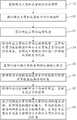
图1为本申请实施例提供的机器人双臂协调运动控制方法的流程图。FIG. 1 is a flowchart of a method for controlling coordinated motion of two arms of a robot according to an embodiment of the present application.
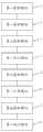
图2为本申请实施例提供的机器人双臂协调运动控制装置的模块图。FIG. 2 is a block diagram of a robot dual-arm coordinated motion control device provided by an embodiment of the present application.
图3为本申请实施例提供的电子设备的结构示意图。FIG. 3 is a schematic structural diagram of an electronic device provided by an embodiment of the present application.
图4为主臂、从臂和物体之间的位置关系示意图。FIG. 4 is a schematic diagram of the positional relationship between the master arm, the slave arm and the object.
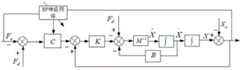
图5为基于位置的自适应力控制模型的示意图。5 is a schematic diagram of a position-based adaptive force control model.
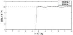
图6为从臂末端工具接触力的仿真结果示意图。Figure 6 is a schematic diagram of the simulation results of the tool contact force from the end of the arm.
具体实施方式Detailed ways
下面将结合本申请实施例中附图,对本申请实施例中的技术方案进行清楚、完整地描述,显然,所描述的实施例仅仅是本申请一部分实施例,而不是全部的实施例。通常在此处附图中描述和示出的本申请实施例的组件可以以各种不同的配置来布置和设计。因此,以下对在附图中提供的本申请的实施例的详细描述并非旨在限制要求保护的本申请的范围,而是仅仅表示本申请的选定实施例。基于本申请的实施例,本领域技术人员在没有做出创造性劳动的前提下所获得的所有其他实施例,都属于本申请保护的范围。The technical solutions in the embodiments of the present application will be clearly and completely described below with reference to the drawings in the embodiments of the present application. Obviously, the described embodiments are only a part of the embodiments of the present application, rather than all the embodiments. The components of the embodiments of the present application generally described and illustrated in the drawings herein may be arranged and designed in a variety of different configurations. Thus, the following detailed description of the embodiments of the application provided in the accompanying drawings is not intended to limit the scope of the application as claimed, but is merely representative of selected embodiments of the application. Based on the embodiments of the present application, all other embodiments obtained by those skilled in the art without creative work fall within the protection scope of the present application.
应注意到:相似的标号和字母在下面的附图中表示类似项,因此,一旦某一项在一个附图中被定义,则在随后的附图中不需要对其进行进一步定义和解释。同时,在本申请的描述中,术语“第一”、“第二”等仅用于区分描述,而不能理解为指示或暗示相对重要性。It should be noted that like numerals and letters refer to like items in the following figures, so once an item is defined in one figure, it does not require further definition and explanation in subsequent figures. Meanwhile, in the description of the present application, the terms "first", "second", etc. are only used to distinguish the description, and cannot be understood as indicating or implying relative importance.
请参阅图1,本申请实施例提供的一种机器人双臂协调运动控制方法,应用于双臂机器人,双臂机器人包括主臂和从臂,从臂的末端工具设置有六维力传感器,六维力传感器用于测量从臂末端工具的三个轴向力和三个轴向的力矩;其特征在于,包括步骤:Referring to FIG. 1 , a method for controlling the coordinated motion of two arms of a robot provided by an embodiment of the present application is applied to a two-arm robot. The two-arm robot includes a master arm and a slave arm. The end tool of the slave arm is provided with a six-dimensional force sensor, and the six The Wei force sensor is used to measure the three axial forces and three axial moments of the tool from the end of the arm; it is characterized in that it includes the steps:
A1.获取主臂和从臂的运动学模型;A1. Obtain the kinematic models of the master arm and the slave arm;
A2.获取主臂和从臂的坐标转换矩阵;A2. Obtain the coordinate transformation matrix of the master arm and the slave arm;
A3.获取主臂的运动轨迹;A3. Obtain the motion trajectory of the main arm;
A4.根据主臂和从臂的运动学模型、主臂和从臂的坐标转换矩阵以及从臂与主臂的运动约束关系,由主臂的运动轨迹计算从臂的运动轨迹;A4. According to the kinematic model of the master arm and the slave arm, the coordinate transformation matrix of the master arm and the slave arm, and the motion constraint relationship between the slave arm and the master arm, the movement track of the slave arm is calculated from the movement track of the master arm;
A5.获取六维力传感器测得的接触力数据;A5. Obtain the contact force data measured by the six-dimensional force sensor;
A6.根据所述从臂的末端位置和所述接触力数据计算被搬运物体的刚度;A6. Calculate the stiffness of the conveyed object according to the end position of the slave arm and the contact force data;
A7.根据所述刚度和BP神经网络预测模型,获取自适应力控制参数;A7. Obtain adaptive force control parameters according to the stiffness and the BP neural network prediction model;
A8.在控制所述从臂沿所述从臂的运动轨迹运动时,根据预设的期望接触力、测得的接触力数据和所述自适应力控制参数,采用基于位置的自适应力控制方法来修正从臂的实际运动轨迹。A8. When controlling the slave arm to move along the movement track of the slave arm, adopt position-based adaptive force control according to the preset expected contact force, the measured contact force data and the adaptive force control parameters method to correct the actual motion trajectory of the slave arm.
该方法在获取主臂的运动轨迹后,根据从臂与主臂的运动约束关系计算从臂的运动轨迹,在控制从臂沿该从臂的运动轨迹运动时,根据六维力传感器事实测量的接触力数据,并根据接触力数据和从臂的末端位置计算被搬运物体的实际刚度,以输入BP神经网络预测模型来获取相匹配的自适应力控制参数,基于位置的自适应力控制,适当修正了从臂的轨迹,从而达到了作用力控制的目的,避免机器人的位置跟踪误差而导致两个机械臂对被搬运物体的作用力过大或不足。After acquiring the movement trajectory of the master arm, the method calculates the movement trajectory of the slave arm according to the motion constraint relationship between the slave arm and the master arm, and when controlling the slave arm to move along the movement trajectory of the slave arm, it measures the Contact force data, and calculate the actual stiffness of the object to be carried according to the contact force data and the position of the end of the arm from the arm, to input the BP neural network prediction model to obtain the matching adaptive force control parameters, position-based adaptive force control, appropriate The trajectory of the slave arm is corrected, so as to achieve the purpose of force control, and avoid the position tracking error of the robot, which causes the force of the two robotic arms to be too large or insufficient on the object to be transported.
实际上,在其它条件相同的情况下,被搬运物体的刚度不同的时候,机械臂对物体的作用力也应该不同,需要与被搬运物体的实际刚度相匹配,从而避免压坏被搬运物体和损坏机械臂本身,该方法能够根据不同刚度的物体自动调节自适应力控制参数,最终实现机械臂与不同刚度的物体接触的自适应力控制。In fact, when other conditions are the same, when the stiffness of the object to be transported is different, the force of the mechanical arm on the object should also be different, which needs to match the actual stiffness of the object to be transported, so as to avoid crushing the object to be transported and damage. For the manipulator itself, the method can automatically adjust the adaptive force control parameters according to objects of different stiffness, and finally realize the adaptive force control of the contact between the manipulator and the objects of different stiffness.
步骤A1中,可通过D-H坐标变换方法分别建立两条机械臂的运动学模型,并以此求解机械臂正运动学方程和逆运动学方程作为机器人控制的基础。In step A1, the kinematic models of the two manipulators can be established respectively by the D-H coordinate transformation method, and the forward kinematic equations and the inverse kinematics equations of the manipulators can be solved based on this as the basis of the robot control.
步骤A2中,主臂和从臂的坐标转换矩阵可通过预先标定得到,标定方法如下:通过空间中不在同一直线上的三个空间点P1、P2、P3,获取该三个点在主臂坐标系下的坐标和在从臂坐标系下的坐标,以P2为原点,(P1-P2)得到的向量为X轴,(P3-P2)得到的向量为Y轴,X轴叉乘Y轴得到Z轴,由计算得到的X轴、Y轴和Z轴构建一个空间坐标系作为两条机械臂的公共坐标系S,通过主臂的正运动学计算得到主臂座坐标系B1到公共坐标系S的变换矩阵为


在一些实施方式中,步骤A3包括:In some embodiments, step A3 includes:
A301.获取待搬运物体的位置信息、尺寸信息和姿态信息;A301. Obtain the position information, size information and attitude information of the object to be transported;
A302.获取目的地位置信息;A302. Obtain destination location information;
A303.根据待搬运物体的位置信息、尺寸信息和姿态信息和目的地位置信息,规划主臂的运动轨迹。A303. Plan the motion trajectory of the main arm according to the position information, size information, attitude information and destination position information of the object to be transported.
例如,对于设置有双目视觉系统的机器人,可通过双目视觉系统获取待搬运物体的位置信息、尺寸信息和姿态信息;在A302中,可采集现场图像并发送至远端的机器人控制器,由操作人员根据现场图像选定物体搬运的目的地位并生成目的地位置信息发回机器人,或者在采集现场图像后通过图像分析方法获取适合放置待搬运物体的区域,并选取其中离物体初始位置最近的区域作为目的地,获取该区域的中心位置信息作为目的地位置信息;在A303中,可通过基于采样的运动规划方法,得到主臂的路点,该主臂的路点表示主臂运动轨迹上的点。 以上只是举例说明,步骤A301-A303的具体实施方式不限于此。For example, for a robot equipped with a binocular vision system, the position information, size information and attitude information of the object to be transported can be obtained through the binocular vision system; in A302, on-site images can be collected and sent to the remote robot controller, The operator selects the destination position of the object to be transported according to the scene image and generates the destination position information and sends it back to the robot. As the destination, the center position information of the area is obtained as the destination position information; in A303, the waypoint of the main arm can be obtained through the sampling-based motion planning method, and the waypoint of the main arm represents the movement trajectory of the main arm point on. The above is only an example, and the specific implementation of steps A301-A303 is not limited thereto.
在本实施例中,步骤A4中,根据以下公式计算由主臂的运动轨迹计算从臂的运动轨迹:In this embodiment, in step A4, the motion trajectory of the slave arm is calculated from the motion trajectory of the master arm according to the following formula:

其中,


见图4,为搬运过程中主臂90、从臂91和物体92之间的位置关系示意图,其中,主臂90的坐标系为{R1},从臂91的坐标系为{R2},主臂90的末端工具坐标系为{E1},从臂91的末端工具坐标系为{E2},物体92的工件坐标系为{P},主臂和从臂在协同运动时有如下关系:Fig. 4 is a schematic diagram of the positional relationship between the

其中,

进一步的,由于在搬运过程中,主臂90的末端工具、从臂91的末端工具、物体92之间是相对静止的(即相对位置固定),且物体92的尺寸是不变的,因此,主臂90末端工具坐标系到从臂91末端工具坐标系之间的转换矩阵是不变的且为常变换矩阵,该常变换矩阵可预先计算得到;所以,从臂与主臂的运动约束关系为


在步骤A6中,可根据以下公式计算被搬运物体的刚度:In step A6, the stiffness of the object to be transported can be calculated according to the following formula:

其中,


在一些实施方式中,见图5,可通过图5中的基于位置的自适应力控制模型(该模型为自适应自适应力控制模型)进行从臂的实际运动轨迹的修正,该基于位置的自适应力控制模型的数学表达式为:In some embodiments, see FIG. 5 , the position-based adaptive force control model (which is an adaptive adaptive force control model) in FIG. The mathematical expression of the adaptive force control model is:

其中,


该基于位置的自适应力控制模型中,引入了实时的力偏差反馈闭环和自适应力控制参数


通过对基于位置的自适应力控制模型的数学表达式进行积分可得到以下计算公式,可根据该公式修正从臂的实际运动轨迹:By integrating the mathematical expression of the position-based adaptive force control model, the following calculation formula can be obtained, according to which the actual motion trajectory of the slave arm can be corrected:

其中,
在该基于位置的自适应力控制模型中,在自适应力控制中引入自适应调整刚度参数,在自适应力控制器中增加实时的力偏差反馈闭环,根据这个力偏差反馈来在线调整自适应力控制器的刚度参数,从而在无需修改任何参数的条件下能够适应不同刚度的物体的表面接触力控制。In the position-based adaptive force control model, the adaptive adjustment stiffness parameter is introduced into the adaptive force control, and the real-time force deviation feedback closed-loop is added to the adaptive force controller, and the adaptive force is adjusted online according to the force deviation feedback. The stiffness parameter of the force controller can adapt to the surface contact force control of objects of different stiffness without modifying any parameters.
进一步的,步骤A8包括:Further, step A8 includes:
A801.把从臂运动轨迹修正量


其中,


A802.根据以下公式修正从臂的位置:A802. Correct the position of the slave arm according to the following formula:

其中,


A803.根据以下公式修正从臂的姿态:A803. Correct the attitude of the slave arm according to the following formula:


其中,


根据上述方法进行如下仿真:According to the above method, the following simulation is performed:
双臂机器人搬运工件的末端期望接触力设置为20N,自适应力控制器的期望惯性矩阵


由上可知,该机器人双臂协调运动控制方法,通过获取所述主臂和从臂的运动学模型;获取所述主臂和从臂的坐标转换矩阵;获取所述主臂的运动轨迹;根据所述主臂和从臂的运动学模型、主臂和从臂的坐标转换矩阵以及从臂与主臂的运动约束关系,由所述主臂的运动轨迹计算所述从臂的运动轨迹;获取所述六维力传感器测得的接触力数据;根据所述从臂的末端位置和所述接触力数据计算被搬运物体的刚度;根据所述刚度和BP神经网络预测模型,获取自适应力控制参数;在控制所述从臂沿所述从臂的运动轨迹运动时,根据预设的期望接触力、测得的接触力数据和所述自适应力控制参数,采用基于位置的自适应力控制方法来修正从臂的实际运动轨迹;从而可避免机器人的位置跟踪误差而导致两个机械臂对被搬运物体的作用力过大或不足。As can be seen from the above, the robot double-arm coordinated motion control method obtains the kinematic model of the master arm and the slave arm; obtains the coordinate transformation matrix of the master arm and the slave arm; obtains the motion trajectory of the master arm; The kinematic model of the master arm and the slave arm, the coordinate transformation matrix of the master arm and the slave arm, and the motion constraint relationship between the slave arm and the master arm, and the movement track of the slave arm is calculated from the movement track of the master arm; obtain The contact force data measured by the six-dimensional force sensor; the stiffness of the object to be transported is calculated according to the end position of the slave arm and the contact force data; the adaptive force control is obtained according to the stiffness and the BP neural network prediction model parameters; when controlling the slave arm to move along the movement track of the slave arm, according to the preset expected contact force, the measured contact force data and the adaptive force control parameters, the position-based adaptive force control is adopted The method is used to correct the actual motion trajectory of the slave arm; thus, the position tracking error of the robot can be avoided and the force of the two manipulator arms on the object being transported is too large or insufficient.
请参阅图2,本申请实施例提供一种机器人双臂协调运动控制装置,包括第一获取模块1、第二获取模块2、第三获取模块3、第一执行模块4、第四获取模块5、第一计算模块6、第五获取模块7、第二执行模块8;Referring to FIG. 2 , an embodiment of the present application provides a robot dual-arm coordinated motion control device, including a
其中,第一获取模块1,用于获取主臂和从臂的运动学模型;Wherein, the
其中,第二获取模块2,用于获取主臂和从臂的坐标转换矩阵;Wherein, the second acquisition module 2 is used to acquire the coordinate transformation matrix of the master arm and the slave arm;
其中,第三获取模块3,用于获取主臂的运动轨迹;Wherein, the
其中,第一执行模块4,用于根据主臂和从臂的运动学模型、主臂和从臂的坐标转换矩阵以及从臂与主臂的运动约束关系,由主臂的运动轨迹计算从臂的运动轨迹;Among them, the first execution module 4 is used to calculate the slave arm from the motion trajectory of the master arm according to the kinematic model of the master arm and the slave arm, the coordinate transformation matrix of the master arm and the slave arm, and the motion constraint relationship between the slave arm and the master arm movement trajectory;
其中,第四获取模块5,用于获取六维力传感器测得的接触力数据;Wherein, the
其中,第一计算模块6,用于根据所述从臂的末端位置和所述接触力数据计算被搬运物体的刚度;Wherein, the
其中,第五获取模块7,用于根据所述刚度和BP神经网络预测模型,获取自适应力控制参数;Wherein, the fifth obtaining
其中,第二执行模块8,用于在控制所述从臂沿所述从臂的运动轨迹运动时,根据预设的期望接触力、测得的接触力数据和所述自适应力控制参数,采用基于位置的自适应力控制方法来修正从臂的实际运动轨迹。Wherein, the
在一些实施方式中,第三获取模块3在获取主臂的运动轨迹时,In some embodiments, when the
获取待搬运物体的位置信息、尺寸信息和姿态信息;Obtain the position information, size information and attitude information of the object to be transported;
获取目的地位置信息;Obtain destination location information;
根据待搬运物体的位置信息、尺寸信息和姿态信息和目的地位置信息,规划主臂的运动轨迹。According to the position information, size information, attitude information and destination position information of the object to be transported, the movement trajectory of the main arm is planned.
在一些实施方式中,第一执行模块4根据以下公式计算由主臂的运动轨迹计算从臂的运动轨迹:In some embodiments, the first execution module 4 calculates the movement trajectory of the slave arm from the movement trajectory of the master arm according to the following formula:

其中,


进一步的,从臂与主臂的运动约束关系为:
在一些实施方式中,第一计算模块6根据以下公式计算被搬运物体的刚度:In some embodiments, the

其中,


在一些实施方式中,步骤A7包括:把第一计算模块6计算得到的刚度值输入到BP神经网络预测模型中,得到对应的自适应力控制参数。In some embodiments, step A7 includes: inputting the stiffness value calculated by the
可设计被搬运物体的不同刚度和自适应力控制参数的映射关系数据集,并把该数据集合作为BP神经网络训练的样本数据,经过BP神经网络训练后,生成BP神经网络预测模型。The mapping relationship data set of different stiffness and adaptive force control parameters of the object to be transported can be designed, and the data set is used as the sample data for BP neural network training. After the BP neural network training, the BP neural network prediction model is generated.
在一些实施方式中,第二执行模块8,根据以下公式修正从臂的实际运动轨迹:In some embodiments, the

其中,


进一步的,第二执行模块8在修正从臂的实际运动轨迹时,Further, when the
把从臂运动轨迹修正量分解为


根据以下公式修正从臂的位置:Correct the position of the slave arm according to the following formula:

其中,


根据以下公式修正从臂的姿态:Correct the attitude of the slave arm according to the following formula:


其中,


由上可知,该机器人双臂协调运动控制装置,通过获取所述主臂和从臂的运动学模型;获取所述主臂和从臂的坐标转换矩阵;获取所述主臂的运动轨迹;根据所述主臂和从臂的运动学模型、主臂和从臂的坐标转换矩阵以及从臂与主臂的运动约束关系,由所述主臂的运动轨迹计算所述从臂的运动轨迹;获取所述六维力传感器测得的接触力数据;根据所述从臂的末端位置和所述接触力数据计算被搬运物体的刚度;根据所述刚度和BP神经网络预测模型,获取自适应力控制参数;在控制所述从臂沿所述从臂的运动轨迹运动时,根据预设的期望接触力、测得的接触力数据和所述自适应力控制参数,采用基于位置的自适应力控制方法来修正从臂的实际运动轨迹;从而可避免机器人的位置跟踪误差而导致两个机械臂对被搬运物体的作用力过大或不足。It can be seen from the above that the robot double-arm coordinated motion control device obtains the kinematic models of the master arm and the slave arm; obtains the coordinate transformation matrix of the master arm and the slave arm; obtains the motion trajectory of the master arm; The kinematic model of the master arm and the slave arm, the coordinate transformation matrix of the master arm and the slave arm, and the motion constraint relationship between the slave arm and the master arm, and the movement track of the slave arm is calculated from the movement track of the master arm; obtain The contact force data measured by the six-dimensional force sensor; the stiffness of the object to be transported is calculated according to the end position of the slave arm and the contact force data; the adaptive force control is obtained according to the stiffness and the BP neural network prediction model parameters; when controlling the slave arm to move along the movement track of the slave arm, according to the preset expected contact force, the measured contact force data and the adaptive force control parameters, the position-based adaptive force control is adopted The method is used to correct the actual motion trajectory of the slave arm; thus, the position tracking error of the robot can be avoided and the force of the two manipulator arms on the object being transported is too large or insufficient.
请参阅图3,本申请实施例还提供一种电子设备100,包括处理器101和存储器102,存储器102中存储有计算机程序,处理器101通过调用存储器102中存储的计算机程序,用于执行上述的机器人双臂协调运动控制方法。Referring to FIG. 3, an embodiment of the present application further provides an
其中,处理器101与存储器102电性连接。处理器101是电子设备100的控制中心,利用各种接口和线路连接整个电子设备的各个部分,通过运行或调用存储在存储器102内的计算机程序,以及调用存储在存储器102内的数据,执行电子设备的各种功能和处理数据,从而对电子设备进行整体监控。The
存储器102可用于存储计算机程序和数据。存储器102存储的计算机程序中包含有可在处理器中执行的指令。计算机程序可以组成各种功能模块。处理器101通过调用存储在存储器102的计算机程序,从而执行各种功能应用以及数据处理。
在本实施例中,电子设备100中的处理器101会按照如下的步骤,将一个或一个以上的计算机程序的进程对应的指令加载到存储器102中,并由处理器101来运行存储在存储器102中的计算机程序,从而实现各种功能:获取所述主臂和从臂的运动学模型;获取所述主臂和从臂的坐标转换矩阵;获取所述主臂的运动轨迹;根据所述主臂和从臂的运动学模型、主臂和从臂的坐标转换矩阵以及从臂与主臂的运动约束关系,由所述主臂的运动轨迹计算所述从臂的运动轨迹;获取所述六维力传感器测得的接触力数据;根据所述从臂的末端位置和所述接触力数据计算被搬运物体的刚度;根据所述刚度和BP神经网络预测模型,获取自适应力控制参数;在控制所述从臂沿所述从臂的运动轨迹运动时,根据预设的期望接触力、测得的接触力数据和所述自适应力控制参数,采用基于位置的自适应力控制方法来修正从臂的实际运动轨迹。In this embodiment, the processor 101 in the electronic device 100 loads the instructions corresponding to the processes of one or more computer programs into the memory 102 according to the following steps, and is executed by the processor 101 and stored in the memory 102 The computer program in the device can realize various functions: obtain the kinematic models of the master arm and the slave arm; obtain the coordinate transformation matrix of the master arm and the slave arm; obtain the motion trajectory of the master arm; The kinematic model of the arm and the slave arm, the coordinate transformation matrix of the master arm and the slave arm, and the motion constraint relationship between the slave arm and the master arm, the movement track of the slave arm is calculated from the movement track of the master arm; contact force data measured by the force sensor; calculate the stiffness of the object to be transported according to the end position of the slave arm and the contact force data; obtain adaptive force control parameters according to the stiffness and the BP neural network prediction model; When controlling the slave arm to move along the movement track of the slave arm, according to the preset expected contact force, the measured contact force data and the adaptive force control parameter, a position-based adaptive force control method is used to correct The actual motion trajectory of the slave arm.
由上可知,该电子设备,通过获取所述主臂和从臂的运动学模型;获取所述主臂和从臂的坐标转换矩阵;获取所述主臂的运动轨迹;根据所述主臂和从臂的运动学模型、主臂和从臂的坐标转换矩阵以及从臂与主臂的运动约束关系,由所述主臂的运动轨迹计算所述从臂的运动轨迹;获取所述六维力传感器测得的接触力数据;根据所述从臂的末端位置和所述接触力数据计算被搬运物体的刚度;根据所述刚度和BP神经网络预测模型,获取自适应力控制参数;在控制所述从臂沿所述从臂的运动轨迹运动时,根据预设的期望接触力、测得的接触力数据和所述自适应力控制参数,采用基于位置的自适应力控制方法来修正从臂的实际运动轨迹;从而可避免机器人的位置跟踪误差而导致两个机械臂对被搬运物体的作用力过大或不足。It can be seen from the above that the electronic device obtains the kinematic models of the master arm and the slave arm; obtains the coordinate transformation matrix of the master arm and the slave arm; obtains the motion trajectory of the master arm; The kinematic model of the slave arm, the coordinate transformation matrix of the master arm and the slave arm, and the motion constraint relationship between the slave arm and the master arm, the movement track of the slave arm is calculated from the movement track of the master arm; the six-dimensional force is obtained The contact force data measured by the sensor; the stiffness of the object to be transported is calculated according to the end position of the slave arm and the contact force data; the adaptive force control parameters are obtained according to the stiffness and the BP neural network prediction model; When the slave arm moves along the movement track of the slave arm, according to the preset expected contact force, the measured contact force data and the adaptive force control parameter, the position-based adaptive force control method is used to correct the slave arm It can avoid the position tracking error of the robot, which causes the force of the two manipulators to be too large or insufficient on the object to be transported.
综上所述,虽然本发明已以优选实施例揭露如上,但上述优选实施例并非用以限制本发明,本领域的普通技术人员,在不脱离本发明的精神和范围内,均可作各种更动与润饰,其方案与本发明实质上相同。In summary, although the present invention has been disclosed above with preferred embodiments, the above preferred embodiments are not intended to limit the present invention. Those of ordinary skill in the art can make various Such alterations and modifications, the solutions of which are substantially the same as those of the present invention.
Claims (7)


Priority Applications (1)
| Application Number | Priority Date | Filing Date | Title |
|---|---|---|---|
| CN202011329284.0ACN112123341B (en) | 2020-11-24 | 2020-11-24 | Robot double arm coordinated motion control method, device and electronic device |
Applications Claiming Priority (1)
| Application Number | Priority Date | Filing Date | Title |
|---|---|---|---|
| CN202011329284.0ACN112123341B (en) | 2020-11-24 | 2020-11-24 | Robot double arm coordinated motion control method, device and electronic device |
Publications (2)
| Publication Number | Publication Date |
|---|---|
| CN112123341A CN112123341A (en) | 2020-12-25 |
| CN112123341Btrue CN112123341B (en) | 2021-03-02 |
Family
ID=73852281
Family Applications (1)
| Application Number | Title | Priority Date | Filing Date |
|---|---|---|---|
| CN202011329284.0AActiveCN112123341B (en) | 2020-11-24 | 2020-11-24 | Robot double arm coordinated motion control method, device and electronic device |
Country Status (1)
| Country | Link |
|---|---|
| CN (1) | CN112123341B (en) |
Families Citing this family (10)
| Publication number | Priority date | Publication date | Assignee | Title |
|---|---|---|---|---|
| TWI742990B (en) | 2021-01-19 | 2021-10-11 | 財團法人工業技術研究院 | Robotic arm system, control method thereof and computer program product thereof |
| CN113146615B (en)* | 2021-01-29 | 2024-12-20 | 广东省科学院智能制造研究所 | Multi-robot collaborative handling control method and device |
| CN115179273B (en)* | 2021-04-02 | 2025-08-12 | 腾讯科技(深圳)有限公司 | Control method and device for double-arm robot, robot and storage medium |
| CN113664813B (en)* | 2021-08-25 | 2022-07-29 | 深圳市优必选科技股份有限公司 | Method and device for controlling double-arm robot, double-arm robot and readable storage medium |
| CN113771044B (en)* | 2021-10-09 | 2022-11-11 | 北京卫星环境工程研究所 | Robot tail end load dynamic stress sensing method |
| CN116197890A (en)* | 2021-12-01 | 2023-06-02 | 腾讯科技(深圳)有限公司 | Control method and device for double-arm robot, conveying method, and double-arm robot |
| CN115716594A (en)* | 2022-11-10 | 2023-02-28 | 中国空间技术研究院杭州中心 | A clamping and conveying device with dual robotic arms and a force control method for the mechanical arms thereof |
| CN116141329B (en)* | 2023-03-06 | 2025-08-08 | 北京理工大学 | A spatial closed-loop dual-arm robot motion control method based on self-correcting control |
| CN117406667B (en)* | 2023-11-20 | 2024-05-10 | 南京工程学院 | A motion control method for stretch bending machine based on digital twin model |
| CN118809676B (en)* | 2024-09-20 | 2025-01-28 | 中国科学院长春光学精密机械与物理研究所 | Force calibration method for integrated parallel platform |
Family Cites Families (5)
| Publication number | Priority date | Publication date | Assignee | Title |
|---|---|---|---|---|
| JP6511900B2 (en)* | 2015-03-25 | 2019-05-15 | セイコーエプソン株式会社 | Piezoelectric drive device and drive method therefor, robot and drive method therefor |
| WO2017033365A1 (en)* | 2015-08-25 | 2017-03-02 | 川崎重工業株式会社 | Remote control robot system |
| CN108515519B (en)* | 2018-04-13 | 2021-03-26 | 珞石(山东)智能科技有限公司 | Grinding path self-adaptive correction method based on force sensor |
| CN111251297B (en)* | 2020-02-20 | 2023-02-07 | 西北工业大学 | A Coordinated Path Planning Method for Dual-arm Space Robots Based on Random Sampling |
| CN111515949B (en)* | 2020-04-23 | 2021-08-10 | 大连理工大学 | Double-arm transmission and reception position selection method for double-arm cooperative robot |
- 2020
- 2020-11-24CNCN202011329284.0Apatent/CN112123341B/enactiveActive
Also Published As
| Publication number | Publication date |
|---|---|
| CN112123341A (en) | 2020-12-25 |
Similar Documents
| Publication | Publication Date | Title |
|---|---|---|
| CN112123341B (en) | Robot double arm coordinated motion control method, device and electronic device | |
| US10864632B2 (en) | Direct teaching method of robot | |
| US10456917B2 (en) | Robot system including a plurality of robots, robot controller and robot control method | |
| JP5528095B2 (en) | Robot system, control apparatus and method thereof | |
| JP4271232B2 (en) | Apparatus, method, program, and recording medium for executing offline programming of robot | |
| TWI673150B (en) | Robot teaching method and robot arm control device | |
| JP5114019B2 (en) | Method for controlling the trajectory of an effector | |
| US9519736B2 (en) | Data generation device for vision sensor and detection simulation system | |
| CN108621162A (en) | A kind of manipulator motion planning method | |
| CN110757454A (en) | Path planning method and device for co-rotating dual robots | |
| CN113319857B (en) | Mechanical arm force and position hybrid control method and device, electronic equipment and storage medium | |
| JP2024512827A (en) | System and method for adaptive compliance-based robot assembly | |
| US11433537B2 (en) | Automatic path generation device | |
| Siradjuddin et al. | A position based visual tracking system for a 7 DOF robot manipulator using a Kinect camera | |
| JP2019014030A (en) | Control device for robot, robot, robot system, and calibration method for camera | |
| JP2019155556A (en) | Control device of robot, robot, robot system, and calibration method for camera | |
| WO2017132905A1 (en) | Method and apparatus for controlling motion system | |
| US20090228144A1 (en) | Method For Calculating Rotation Center Point And Axis Of Rotation, Method For Generating Program, Method For Moving Manipulator And Positioning Device, And Robotic System | |
| CN110154043B (en) | Robot system for learning control based on machining result and control method thereof | |
| WO2018214156A1 (en) | Method of correcting locomotion control command of robot, and related apparatus for same | |
| JPH01146645A (en) | Tracing control method | |
| Bohan et al. | Research on position-based impedance control in cartesian space of robot manipulators | |
| Washizu et al. | Iterative learning-based trajectory generation of robot manipulator to reproduce force response of teaching device | |
| JPS5958503A (en) | Tool offset teaching method for robot | |
| CN116276995B (en) | Impedance control-based man-machine cooperation method with zero-space obstacle avoidance capability |
Legal Events
| Date | Code | Title | Description |
|---|---|---|---|
| PB01 | Publication | ||
| PB01 | Publication | ||
| SE01 | Entry into force of request for substantive examination | ||
| SE01 | Entry into force of request for substantive examination | ||
| GR01 | Patent grant | ||
| GR01 | Patent grant |