Movatterモバイル変換


[0]ホーム

URL:


CN112122146A - Function and appearance integrated test equipment - Google Patents

Function and appearance integrated test equipment
Download PDF

Info

Publication number
CN112122146A
CN112122146ACN202011058064.9ACN202011058064ACN112122146ACN 112122146 ACN112122146 ACN 112122146ACN 202011058064 ACN202011058064 ACN 202011058064ACN 112122146 ACN112122146 ACN 112122146A
Authority
CN
China
Prior art keywords
tray
feeding
appearance
moving module
products
Prior art date
Legal status (The legal status is an assumption and is not a legal conclusion. Google has not performed a legal analysis and makes no representation as to the accuracy of the status listed.)
Granted
Application number
CN202011058064.9A
Other languages
Chinese (zh)
Other versions
CN112122146B (en
Inventor
杨建设
张雅凯
缪凯
贾勇
Current Assignee (The listed assignees may be inaccurate. Google has not performed a legal analysis and makes no representation or warranty as to the accuracy of the list.)
Kunshan Yexin Electronic Technology Co ltd
Original Assignee
Kunshan Yexin Electronic Technology Co ltd
Priority date (The priority date is an assumption and is not a legal conclusion. Google has not performed a legal analysis and makes no representation as to the accuracy of the date listed.)
Filing date
Publication date
Application filed by Kunshan Yexin Electronic Technology Co ltdfiledCriticalKunshan Yexin Electronic Technology Co ltd
Priority to CN202011058064.9ApriorityCriticalpatent/CN112122146B/en
Publication of CN112122146ApublicationCriticalpatent/CN112122146A/en
Application grantedgrantedCritical
Publication of CN112122146BpublicationCriticalpatent/CN112122146B/en
Activelegal-statusCriticalCurrent
Anticipated expirationlegal-statusCritical

Links

Images

Classifications

Landscapes

Abstract

Translated fromChinese

本发明提供了一种功能外观一体测试设备,包括:料盘入料机构;功能测试机构,用于对产品进行功能测试;测试抓取机构,用于抓取产品并移动至功能测试机构,并将检测完成的良品移动至良品出料机构;外观测试机构,用于确认产品的数量、检查产品的外观和放置方向;良品出料机构;补料抓取机构,用于将不良品移动至不良品放置机构,并装填良品;补料传输机构,为补料抓取机构提供良品;以及不良品放置机构,用于放置不良品。本发明提供的功能外观一体测试设备,既可以对产品进行功能测试,也可以对产品进行外观测试,可以简化测试过程,无需人工在两台设备之间搬运料盘,从而提高测试效率、减小人力投入。

Figure 202011058064

The invention provides a functional and appearance integrated testing device, comprising: a tray feeding mechanism; a functional testing mechanism for performing functional testing on a product; a testing grasping mechanism for grasping the product and moving to the functional testing mechanism, and Move the inspected good products to the good product discharge mechanism; the appearance testing mechanism is used to confirm the quantity of products, check the appearance and placement direction of the products; the good product discharge mechanism; Good product placement mechanism for filling good products; feeding transfer mechanism for providing good products for the feeding grabbing mechanism; and defective product placement mechanism for placing defective products. The function and appearance integrated testing equipment provided by the present invention can not only perform functional testing on products, but also perform appearance testing on products, simplify the testing process, and do not need to manually move the tray between the two devices, thereby improving testing efficiency and reducing Human input.

Figure 202011058064

Description

Translated fromChinese
功能外观一体测试设备Function and appearance integrated test equipment

技术领域technical field

本发明属于芯片测试技术领域,更具体地说,是涉及一种功能外观一体测试设备。The invention belongs to the technical field of chip testing, and more particularly relates to a functional and appearance integrated testing device.

背景技术Background technique

在芯片出货之前,需要对芯片进行功能测试和外观测试,保证出货质量。电性测试、高压测试等功能测试采用功能测试设备完成,外观测试采用外观测试设备完成。两种测试设备分别对芯片进行工艺测试,导致测试过程繁琐、测试时间较长、人力投入也较大。Before the chip is shipped, it is necessary to perform functional and appearance tests on the chip to ensure the quality of the shipment. Functional tests such as electrical test and high voltage test are completed by functional test equipment, and appearance test is completed by appearance test equipment. The two kinds of test equipments separately perform process test on the chip, which leads to cumbersome test process, long test time and large manpower input.

发明内容SUMMARY OF THE INVENTION

本发明实施例的目的在于提供一种功能外观一体测试设备,以解决现有技术中存在的采用两种测试设备对芯片进行测试,导致测试过程繁琐、测试时间长、人力投入大的技术问题。The purpose of the embodiments of the present invention is to provide an integrated function-appearance testing device to solve the technical problems in the prior art that two kinds of testing devices are used to test chips, resulting in cumbersome testing process, long testing time, and large manpower input.

为实现上述目的,本发明采用的技术方案是:提供一种功能外观一体测试设备,包括:In order to achieve the above-mentioned purpose, the technical solution adopted in the present invention is to provide a functional and appearance integrated testing equipment, including:

料盘入料机构,用于运输装载有待检测产品的料盘,所述料盘入料机构的传输方向沿Y轴设置;The tray feeding mechanism is used to transport the tray loaded with the product to be tested, and the transmission direction of the tray feeding mechanism is set along the Y axis;

功能测试机构,用于对产品进行功能测试;Functional testing agency for functional testing of products;

测试抓取机构,用于从所述料盘入料机构上的料盘中抓取产品并移动至所述功能测试机构,并将检测完成的良品移动至良品出料机构以及将检测完成的不良品移动至不良品放置机构;The test grabbing mechanism is used to grab the product from the tray on the tray feeding mechanism and move it to the functional testing mechanism, and move the inspected good products to the good product discharge mechanism and the inspected defective products. The good product is moved to the bad product placement mechanism;

外观测试机构,用于确认产品的数量、检查产品的外观和放置方向;Appearance testing agency to confirm the quantity of the product, check the appearance and placement direction of the product;

良品出料机构,用于运输装载有良品的料盘,所述良品出料机构的传输方向沿Y轴设置;The good product discharging mechanism is used to transport the tray loaded with good products, and the transmission direction of the good product discharging mechanism is set along the Y axis;

补料抓取机构,用于将所述良品出料机构中外观不良和放置方向错误的产品移动至所述不良品放置机构,并装填良品;The feeding and grabbing mechanism is used to move the products with poor appearance and wrong placement direction in the good product discharging mechanism to the defective product placement mechanism, and fill the good products;

补料传输机构,为所述补料抓取机构提供良品;以及a feeding transfer mechanism to provide good products for the feeding grabbing mechanism; and

不良品放置机构,用于放置功能不良品、外观不良和放置方向错误的产品。The defective product placement mechanism is used to place defective functional products, products with poor appearance and wrong placement.

在一个实施例中,所述料盘入料机构、所述功能测试机构、所述良品出料机构、所述不良品放置机构沿X轴方向依次排列设置。In one embodiment, the tray feeding mechanism, the functional testing mechanism, the good product discharging mechanism, and the defective product placing mechanism are arranged in sequence along the X-axis direction.

在一个实施例中,所述补料传输机构的传输方向沿Y轴设置,且所述补料传输机构设于所述功能测试机构和所述良品出料机构之间。In one embodiment, the conveying direction of the feeding feeding mechanism is arranged along the Y axis, and the feeding feeding mechanism is disposed between the functional testing mechanism and the good product discharging mechanism.

在一个实施例中,所述测试抓取机构包括第一X轴移动模组、连接于所述第一X轴移动模组的第一Z轴移动模组、连接于所述第一Z轴移动模组的第一抓料组件、第二X轴移动模组、连接于所述第二X轴移动模组的第二Z轴移动模组、连接于所述第二Z轴移动模组的第二抓料组件,所述第一抓料组件用于从所述料盘入料机构上的料盘中抓取产品并移动至所述功能测试机构,所述第二抓料组件用于将检测完成的良品移动至所述良品出料机构以及将检测出的不良品移动至所述不良品放置机构。In one embodiment, the test grasping mechanism includes a first X-axis moving module, a first Z-axis moving module connected to the first X-axis moving module, and a first Z-axis moving module connected to the first Z-axis moving module. The first grabbing component of the module, the second X-axis moving module, the second Z-axis moving module connected to the second X-axis moving module, the second Z-axis moving module connected to the second Z-axis moving module Two material grabbing components, the first material grabbing component is used for grabbing the product from the material tray on the material tray feeding mechanism and moving to the function testing mechanism, the second material grabbing component is used for testing the The completed good products are moved to the good product discharging mechanism and the detected defective products are moved to the defective product placement mechanism.

在一个实施例中,所述补料抓取机构包括第三X轴移动模组、连接于所述第三X轴移动模组的第三Z轴移动模组以及连接于所述第三Z轴移动模组的第三抓料组件。In one embodiment, the feeding and grabbing mechanism includes a third X-axis moving module, a third Z-axis moving module connected to the third X-axis moving module, and a third Z-axis moving module connected to the third Z-axis The third grabbing component of the mobile module.

在一个实施例中,所述功能外观一体测试设备还包括工作底板以及固定于所述工作底板上的工作支架,所述料盘入料机构、所述功能测试机构、所述补料传输机构、所述良品出料机构以及所述不良品放置机构均固定于所述工作底板上,所述第一X轴移动模组、所述第二X轴移动模组、所述第三X轴移动模组及所述外观测试机构均固定于所述工作支架上。In one embodiment, the functional and appearance integrated testing equipment further includes a working base plate and a working bracket fixed on the working base plate, the tray feeding mechanism, the functional testing mechanism, the feeding transmission mechanism, The good product discharging mechanism and the defective product placing mechanism are all fixed on the working base plate, the first X-axis moving module, the second X-axis moving module, and the third X-axis moving module Both the group and the appearance testing mechanism are fixed on the working bracket.

在一个实施例中,所述功能测试机构包括Y轴移动模组、由所述Y轴移动模组驱动的测试下座、测试升降组件、以及由所述测试升降组件驱动且用于下压所述测试下座的测试上座。In one embodiment, the functional testing mechanism includes a Y-axis moving module, a test lower seat driven by the Y-axis moving module, a test lift assembly, and a test lift driven by the test lift assembly and used for pressing down Test the upper test seat of the lower test seat.

在一个实施例中,所述料盘入料机构包括:In one embodiment, the tray feeding mechanism includes:

料盘分层机构,包括用于升降堆叠的料盘的第一升降组件以及用于分离最底层料盘和其他料盘的第一承托组件;A material tray layering mechanism, including a first lifting component for lifting and stacking the material trays and a first supporting component for separating the bottommost material tray and other material trays;

料盘移动机构,用于输送从所述料盘分层机构中分离出的料盘;以及a tray moving mechanism for conveying the trays separated from the tray layering mechanism; and

料盘堆叠机构,用于堆叠经过所述料盘移动机构运输的料盘,所述料盘堆叠机构包括用于支撑堆叠料盘的第二承托组件以及用于将所述料盘移动机构上的料盘推顶至堆叠料盘的底部的第二升降组件。A tray stacking mechanism for stacking trays transported by the tray moving mechanism, the tray stacking mechanism comprising a second supporting component for supporting the stacked trays and a tray for moving the tray on the tray A second lift assembly that pushes the tray to the bottom of the stack tray.

在一个实施例中,所述料盘移动机构包括传输驱动件、由所述传输驱动件驱动且用于放置料盘的承载盘、用于将料盘卡紧于所述承载盘中的卡紧组件以及用于导向料盘的导轨结构。In one embodiment, the tray moving mechanism includes a transport drive, a carrier tray driven by the transport driver and used to place the tray, and a chuck for clamping the tray in the carrier tray Assembly and guide rail structure for guiding the tray.

在一个实施例中,所述卡紧组件包括固定于所述承载盘的钩爪气缸、连接于所述钩爪气缸输出端且用于卡紧固定料盘的钩爪本体以及使所述钩爪本体转动连接于所述承载盘的钩爪销。In one embodiment, the clamping assembly includes a hook cylinder fixed on the carrier plate, a hook body connected to the output end of the hook cylinder and used for clamping and fixing the material tray, and a hook body connected to the output end of the hook cylinder for clamping and fixing the material tray. The body is rotatably connected to the hook pin of the carrier plate.

本发明提供的功能外观一体测试设备的有益效果在于:与现有技术相比,本发明功能外观一体测试设备包括料盘入料机构、功能测试机构、测试抓取机构、外观测试机构、良品出料机构、补料抓取机构、补料传输机构和不良品放置机构,产品通过料盘入料机构移动,测试抓取机构抓取料盘入料机构上的产品至功能测试机构进行功能测试,功能测试不合格的产品由测试抓取机构抓取至不良品放置机构,功能测试合格的产品由测试抓取机构抓取至良品出料机构,并有外观测试机构对良品出料机构上的产品进行外观测试,外观测试不合格的产品由补料抓取机构抓取至不良品放置机构,并由补料抓取机构从补料传输机构抓取产品装填至良品出料机构上的料盘。如此,该功能外观一体测试设备既可以对产品进行功能测试,也可以对产品进行外观测试,可以简化测试过程,无需人工在两台设备之间搬运料盘,从而提高测试效率、减小人力投入。The beneficial effect of the integrated function and appearance test equipment provided by the present invention is that compared with the prior art, the function and appearance integrated test equipment of the present invention includes a tray feeding mechanism, a function testing mechanism, a test grasping mechanism, an appearance testing mechanism, and a good product output mechanism. The feeding mechanism, the feeding grabbing mechanism, the feeding transmission mechanism and the defective product placement mechanism, the product moves through the feeding mechanism of the feeding tray, and the test grasping mechanism grabs the product on the feeding mechanism of the feeding tray to the functional testing mechanism for functional testing. Products that fail the functional test are grabbed by the test grabbing mechanism to the defective product placement mechanism, products that pass the functional test are grabbed by the test grabbing mechanism to the good product discharge mechanism, and there is an appearance test mechanism for the products on the good product discharge mechanism. Appearance test is carried out. Products that fail the appearance test are grabbed by the replenishment grabbing mechanism to the defective product placement mechanism, and the replenishment grabbing mechanism grabs the product from the replenishment transmission mechanism and loads it to the tray on the good product discharge mechanism. In this way, the function and appearance integrated testing equipment can not only perform functional tests on products, but also perform appearance tests on products, which can simplify the testing process and eliminate the need to manually move trays between the two devices, thereby improving testing efficiency and reducing labor input. .

附图说明Description of drawings

为了更清楚地说明本发明实施例中的技术方案,下面将对实施例或现有技术描述中所需要使用的附图作简单地介绍,显而易见地,下面描述中的附图仅仅是本发明的一些实施例,对于本领域普通技术人员来讲,在不付出创造性劳动性的前提下,还可以根据这些附图获得其他的附图。In order to illustrate the technical solutions in the embodiments of the present invention more clearly, the following briefly introduces the accompanying drawings that need to be used in the description of the embodiments or the prior art. Obviously, the drawings in the following description are only for the present invention. In some embodiments, for those of ordinary skill in the art, other drawings can also be obtained according to these drawings without any creative effort.

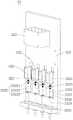
图1为本发明实施例提供的功能外观一体测试设备的结构示意图;FIG. 1 is a schematic structural diagram of a function and appearance integrated testing device provided by an embodiment of the present invention;

图2为本发明实施例提供的料盘入料机构的立体结构图;2 is a three-dimensional structural diagram of a tray feeding mechanism provided by an embodiment of the present invention;

图3为本发明实施例提供的第一升降组件的立体结构图;3 is a three-dimensional structural diagram of a first lifting assembly provided by an embodiment of the present invention;

图4为本发明实施例提供的料盘移动机构的立体结构图;4 is a three-dimensional structural diagram of a material tray moving mechanism provided by an embodiment of the present invention;

图5为本发明实施例提供的承载盘和卡紧组件的立体结构图;FIG. 5 is a three-dimensional structural diagram of a carrier plate and a clamping assembly provided by an embodiment of the present invention;

图6为本发明实施例提供的承载盘和卡紧组件的爆炸结构图;6 is an exploded structural diagram of a carrier plate and a clamping assembly provided by an embodiment of the present invention;

图7为本发明实施例提供的第二升降组件的立体结构图;7 is a three-dimensional structural diagram of a second lifting assembly provided by an embodiment of the present invention;

图8为本发明实施例提供的Y轴移动模组的立体结构图;8 is a three-dimensional structural diagram of a Y-axis moving module provided by an embodiment of the present invention;

图9为本发明实施例提供的第一X轴移动模组、第二X轴移动模组和第三X轴移动模组的立体结构图;9 is a three-dimensional structural diagram of a first X-axis moving module, a second X-axis moving module, and a third X-axis moving module provided by an embodiment of the present invention;

图10为本发明实施例提供的第一抓料组件的立体结构图;FIG. 10 is a three-dimensional structural view of a first material grabbing assembly provided by an embodiment of the present invention;

图11为本发明实施例提供的补料传输机构的立体结构图。FIG. 11 is a three-dimensional structural diagram of a feeding transmission mechanism provided by an embodiment of the present invention.

其中,图中各附图标记:Among them, each reference sign in the figure:

1-料盘入料机构;11-料盘分层机构;111-第一升降组件;1111-升降电机;1112-带轮组件;1113-升降螺杆;1114-第一升降支架;11141-第一升降底板;11142-第二支撑柱;11143-第一推顶板;1115-升降安装板;1116-第一支撑柱;112-第一承托组件;1121-第一伸缩气缸;113-第一定位结构;1131-第一定位柱;1132-第一高度传感器;12-料盘移动机构;121-传输驱动件;1211-传输电机;1212-传输丝杆;1213-传输螺母座;122-承载盘;1221-挡板;1222-钩爪缺口;123-卡紧组件;1231-钩爪气缸;12310-环形卡槽;1232-钩爪本体;12321-连接部;123210-条形孔;12322-钩爪部;1233-钩爪销;124-导轨结构;1241-轨道座;1242-导轨本体;13-料盘堆叠机构;131-第二升降组件;1311-升降气缸;1312-第二升降支架;13121-第二升降底板;13122-第三支撑柱;13133-第二推顶板;132-第二承托组件;1321-第二伸缩气缸;133-第二定位结构;1331-第二定位柱;1332-第二高度传感器;2-功能测试机构;21-Y轴移动模组;211-Y轴丝杆;212-Y轴螺母块;213-Y轴滑轨;214-梭车;3-测试抓取机构;31-第一X轴移动模组;32-第二X轴移动模组;33-第一抓料组件;331-抓料安装板;332-吸嘴组件;3321-吸嘴气缸;3322-连接架;33221-第一水平部;33222-竖直部;33223-第二水平部;3323-缓冲件;3324-吸嘴本体;3325-吸嘴座;3326-抓料滑轨;3327-抓料滑块;333-气管连接器;4-外观测试机构;5-良品出料机构;6-补料抓取机构;61-第三X轴移动模组;7-补料传输机构;71-补料电机;72-补料丝杆;73-补料螺母块;74-补料滑块;75-补料滑轨;8-不良品放置机构;91-工作底板;92-工作支架。1-feeding mechanism of material tray; 11-layering mechanism of material tray; 111-first lifting component; 1111-lifting motor; 1112-belt wheel component; 1113-lifting screw; Lifting bottom plate; 11142-second support column; 11143-first ejector plate; 1115-lifting installation plate; 1116-first support column; 112-first support assembly; 1121-first telescopic cylinder; 113-first positioning Structure; 1131-first positioning column; 1132-first height sensor; 12-material tray moving mechanism; 121-transmission drive; 1211-transmission motor; 1212-transmission screw; 1213-transmission nut seat; 122-carrying plate ;1221-baffle plate; 1222-claw gap; 123-clamping assembly; 1231-claw cylinder; 12310-ring groove; 1232-claw body; 12321-connecting part; Claw; 1233 - hook pin; 124 - guide rail structure; 1241 - track seat; 1242 - guide rail body; 13 - tray stacking mechanism; 131 - second lifting assembly; 1311 - lifting cylinder; 1312 - second lifting bracket; 13121-the second lifting bottom plate; 13122-the third support column; 13133-the second ejector plate; 132-the second bearing assembly; 1321-the second telescopic cylinder; 133-the second positioning structure; 1331-the second positioning column; 1332-Second height sensor; 2-Function test mechanism; 21-Y-axis moving module; 211-Y-axis screw; 212-Y-axis nut block; 213-Y-axis slide rail; 214-shuttle car; 3-test Grab mechanism; 31-first X-axis moving module; 32-second X-axis moving module; 33-first grab assembly; 331- grab mounting plate; 332-nozzle assembly; 3321-nozzle cylinder 3322-connecting frame; 33221-first horizontal part; 33222-vertical part; 33223-second horizontal part; 3327-grasping slider; 333-trachea connector; 4-appearance testing mechanism; 5-good product discharging mechanism; 6-feeding grabbing mechanism; 61-third X-axis moving module; 7-feeding transmission mechanism ;71-feeding motor; 72-feeding screw; 73-feeding nut block; 74-feeding slider; 75-feeding slide rail; 8-defective product placement mechanism; 91-working bottom plate; 92-work bracket.

具体实施方式Detailed ways

为了使本发明所要解决的技术问题、技术方案及有益效果更加清楚明白,以下结合附图及实施例,对本发明进行进一步详细说明。应当理解,此处所描述的具体实施例仅仅用以解释本发明,并不用于限定本发明。In order to make the technical problems, technical solutions and beneficial effects to be solved by the present invention clearer, the present invention will be further described in detail below with reference to the accompanying drawings and embodiments. It should be understood that the specific embodiments described herein are only used to explain the present invention, but not to limit the present invention.

需要说明的是,当元件被称为“固定于”或“设置于”另一个元件,它可以直接在另一个元件上或者间接在该另一个元件上。当一个元件被称为是“连接于”另一个元件,它可以是直接连接到另一个元件或间接连接至该另一个元件上。It should be noted that when an element is referred to as being "fixed to" or "disposed on" another element, it can be directly on the other element or indirectly on the other element. When an element is referred to as being "connected to" another element, it can be directly connected to the other element or indirectly connected to the other element.

需要理解的是,术语“长度”、“宽度”、“上”、“下”、“前”、“后”、“左”、“右”、“竖直”、“水平”、“顶”、“底”、“内”、“外”等指示的方位或位置关系为基于附图所示的方位或位置关系,仅是为了便于描述本发明和简化描述,而不是指示或暗示所指的装置或元件必须具有特定的方位、以特定的方位构造和操作,因此不能理解为对本发明的限制。It is to be understood that the terms "length", "width", "upper", "lower", "front", "rear", "left", "right", "vertical", "horizontal", "top" , "bottom", "inside", "outside", etc. indicate the orientation or positional relationship based on the orientation or positional relationship shown in the accompanying drawings, only for the convenience of describing the present invention and simplifying the description, rather than indicating or implying the indicated A device or element must have a particular orientation, be constructed and operate in a particular orientation, and therefore should not be construed as limiting the invention.

此外,术语“第一”、“第二”仅用于描述目的,而不能理解为指示或暗示相对重要性或者隐含指明所指示的技术特征的数量。由此,限定有“第一”、“第二”的特征可以明示或者隐含地包括一个或者更多个该特征。在本发明的描述中,“多个”的含义是两个或两个以上,除非另有明确具体的限定。In addition, the terms "first" and "second" are only used for descriptive purposes, and should not be construed as indicating or implying relative importance or implying the number of indicated technical features. Thus, a feature defined as "first", "second" may expressly or implicitly include one or more of that feature. In the description of the present invention, "plurality" means two or more, unless otherwise expressly and specifically defined.

现对本发明实施例提供的功能外观一体测试设备进行说明。功能外观一侧测试设备可对芯片等产品进行功能测试和外观测试。The function-appearance integrated testing device provided by the embodiment of the present invention will now be described. The functional and appearance side test equipment can perform functional and appearance tests on products such as chips.

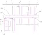
在本发明的其中一个实施例中,请参阅图1,功能外观一体测试设备包括料盘入料机构1、功能测试机构2、测试抓取机构3、外观测试机构4、良品出料机构5、补料抓取机构6、补料传输机构7以及不良品放置机构8。料盘入料机构1的传输方向沿Y轴设置,料盘入料机构1用于运输装载有待检测产品的料盘,可以将装有待检测产品的料盘移动至测试抓取机构3能够抓取的位置。功能测试机构2用于对产品进行功能测试,如电性测试、高压测试等,其测试项目此处不作限定。测试抓取机构3可以从料盘入料机构1上的料盘中抓取产品并移动至功能测试机构2,供功能测试机构2对产品进行功能测试。外观测试机构4用于确认产品的数量、检查产品的外观和放置方向。良品出料机构5的传输方向沿Y轴设置,且用于运输装载有良品的料盘。补料抓取机构6用于将良品出料机构5中外观不良和放置方向错误的产品移动至不良品放置机构8,并装填良品。补料传输机构7为补料抓取机构6提供良品,不良品放置机构8则用于放置不良品。具体地,在该功能外观一体测试设备工作时,待检测产品放置在料盘上,由料盘入料机构1传输,传输至预定位置时,测试抓取机构3从料盘入料机构1上抓取产品,并将产品转移至功能测试机构2,由功能测试机构2对产品进行功能测试,功能测试合格的产品由测试抓取机构3移动至良品出料机构5的料盘上,功能测试不合格的产品由测试抓取机构3移动至不良品放置机构8。良品出料机构5带动其上的料盘沿Y轴方向继续运动至外观检测机构,外观测试机构4对料盘上的产品进行点数和外观检测,如果料盘上缺料,则补料抓取机构6从补料传输机构7上抓取良品装填至缺料位,如果料盘上的产品有外观瑕疵或者放置方向错误,则补料抓取机构6先将外观瑕疵或者放置方向错误的产品抓取至不良品放置机构8,然后从补料传输机构7上抓取良品装填至缺料位,使得经过外观测试和功能测试的良品填满良品出料机构5上的料盘,并由良品出料机构5移动出料。如此,该功能外观一体测试设备既可以对产品进行功能测试,也可以对产品进行外观测试,可以简化测试过程,无需人工在两台设备之间搬运料盘,从而提高测试效率、减小人力投入。In one of the embodiments of the present invention, please refer to FIG. 1, the functional and appearance integrated testing equipment includes atray feeding mechanism 1, afunctional testing mechanism 2, a test grabbing mechanism 3, an appearance testing mechanism 4, a goodproduct discharging mechanism 5, Thereplenishment grabbing mechanism 6 , thereplenishment transmission mechanism 7 and the defectiveproduct placement mechanism 8 . The transmission direction of thetray feeding mechanism 1 is set along the Y axis. Thetray feeding mechanism 1 is used to transport the tray loaded with the product to be tested, and the tray containing the product to be tested can be moved to the test grasping mechanism 3 can be grasped s position. Thefunctional testing agency 2 is used to perform functional testing on the product, such as electrical testing, high-voltage testing, etc., and the testing items are not limited here. The test grabbing mechanism 3 can grab the product from the tray on thetray feeding mechanism 1 and move it to thefunctional testing mechanism 2 for thefunctional testing mechanism 2 to perform functional testing on the product. The appearance testing mechanism 4 is used to confirm the number of products, and check the appearance and placement direction of the products. The conveying direction of the goodproduct discharging mechanism 5 is set along the Y axis, and is used to transport the tray loaded with the good products. The feeding and grabbingmechanism 6 is used to move the products with poor appearance and wrong placement direction in the goodproduct discharging mechanism 5 to the defectiveproduct placing mechanism 8 and load the good products. Thefeeding conveying mechanism 7 provides good products for thefeeding grabbing mechanism 6, and the defectiveproduct placing mechanism 8 is used for placing defective products. Specifically, when the function-appearance integrated testing equipment is in operation, the product to be tested is placed on the tray and transmitted by thetray feeding mechanism 1. When it is transmitted to a predetermined position, the test grasping mechanism 3 is transferred from thetray feeding mechanism 1 Grab the product and transfer the product to thefunctional testing mechanism 2. Thefunctional testing mechanism 2 performs functional testing on the product. Products that pass the functional test are moved by the testing grasping mechanism 3 to the tray of the goodproduct discharging mechanism 5. The functional test is performed. Unqualified products are moved by the test grabbing mechanism 3 to the defectiveproduct placement mechanism 8 . The goodproduct discharging mechanism 5 drives the material tray on it to continue to move to the appearance inspection mechanism along the Y-axis direction, and the appearance testing mechanism 4 conducts point count and appearance inspection of the products on the material tray. Themechanism 6 grabs the good products from thefeeding conveying mechanism 7 and fills them to the shortage level. If the products on the tray have defects in appearance or are placed in the wrong direction, thefeeding grabbing mechanism 6 first grabs the products with defects in appearance or in the wrong direction. Take it to the defectiveproduct placement mechanism 8, and then grab the good product from thefeeding conveying mechanism 7 and fill it to the shortage level, so that the good product that has passed the appearance test and function test fills the tray on the goodproduct discharge mechanism 5, and the good product is discharged. Thefeeding mechanism 5 moves and discharges the material. In this way, the function and appearance integrated testing equipment can not only perform functional tests on products, but also perform appearance tests on products, which can simplify the testing process and eliminate the need to manually move trays between the two devices, thereby improving testing efficiency and reducing labor input. .

在本发明的其中一个实施例中,请参阅图1,料盘入料机构1、功能测试机构2、良品出料机构5、不良品放置机构8沿X轴方向依次排列,使产品也沿该方向逐渐移动。由于料盘入料机构1和良品出料机构5的传输方向均沿Y轴设置,当料盘入料机构1、功能测试机构2、良品出料机构5、不良品放置机构8沿X轴方向依次排列时,可以充分利用X轴方向的空间,合理布局,减小功能外观一体测试设备占用的空间。In one embodiment of the present invention, please refer to FIG. 1, thetray feeding mechanism 1, thefunction testing mechanism 2, the goodproduct discharging mechanism 5, and the defectiveproduct placing mechanism 8 are arranged in sequence along the X-axis direction, so that the products are also arranged along the X axis. The direction moves gradually. Since the transmission direction of thetray feeding mechanism 1 and the goodproduct discharging mechanism 5 are all set along the Y axis, when the feedingtray feeding mechanism 1, thefunction testing mechanism 2, the goodproduct discharging mechanism 5, and the defectiveproduct placing mechanism 8 are along the X axis direction When arranged in sequence, the space in the X-axis direction can be fully utilized, the layout is reasonable, and the space occupied by the integrated function and appearance test equipment can be reduced.

可选地,补料传输机构7的传输方向也沿Y轴设置,使补料盘可以沿Y轴方向移动,补料抓取机构6可以沿X轴方向移动,从而与补料盘的移动方向配合,可以抓取补料盘上任一位置的良品。这样,补料抓取机构6的第三X轴移动模组61和测试抓取机构3上的第一X轴移动模组31和第二X轴移动模组32平行设置,可固定于同一工作支架92上,更便于布局以节省空间。Optionally, the transmission direction of thefeeding conveying mechanism 7 is also set along the Y axis, so that the feeding tray can move along the Y axis, and thefeeding grasping mechanism 6 can move along the X axis, so as to be consistent with the moving direction of the feeding tray. With cooperation, you can grab good products at any position on the feeding tray. In this way, the thirdX-axis moving module 61 of thefeeding grasping mechanism 6 and the firstX-axis moving module 31 and the secondX-axis moving module 32 on the test grasping mechanism 3 are arranged in parallel, and can be fixed in the same work On thebracket 92, the layout is more convenient to save space.

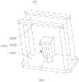
在本发明的其中一个实施例中,请参阅图2,料盘入料机构1包括料盘分层机构11、料盘移动机构12和料盘堆叠机构13。料盘分层机构11用于将堆叠料盘中的最底层料盘分离至料盘移动机构12上,无需人工分离料盘,可以提高料盘传输装置的自动化程度。具体地,料盘分层机构11包括第一升降组件111和第一承托组件112,堆叠料盘放置在第一升降组件111上,第一升降组件111能够带动堆叠料盘上下移动,第一承托组件112则用于承托除最底层料盘的其他料盘,使最底层料盘能够和其他料盘分离。在需要将最底层料盘分离时,第一升降组件111将堆叠料盘升起或下降至预定高度,第一承托组件112承托除最底层料盘的其他料盘,使第一升降组件111上仅剩一个料盘,第一升降组件111下降,将该料盘下落至料盘移动机构12的承载盘122上,从而实现最底层料盘和其他料盘的分离。请参阅图3,料盘移动机构12将料盘分层机构11分离出的料盘输送至测试工位,供测试机构取料,然后再将空料盘运输至料盘堆叠机构13进行堆叠。In one embodiment of the present invention, please refer to FIG. 2 , thetray feeding mechanism 1 includes a tray layering mechanism 11 , atray moving mechanism 12 and atray stacking mechanism 13 . The tray layering mechanism 11 is used for separating the bottommost tray in the stacking trays to thetray moving mechanism 12, without manual separation of the trays, which can improve the automation degree of the tray transmission device. Specifically, the tray layering mechanism 11 includes afirst lifting component 111 and a first supportingcomponent 112. The stacking tray is placed on thefirst lifting component 111. Thefirst lifting component 111 can drive the stacking tray to move up and down. The supportingcomponent 112 is used to support other trays except the bottom tray, so that the bottom tray can be separated from the other trays. When the bottom tray needs to be separated, thefirst lifting component 111 lifts or lowers the stacked trays to a predetermined height, and the first supportingcomponent 112 supports other trays except the bottom tray, so that thefirst lifting component 111 There is only one tray left, thefirst lifting assembly 111 descends, and the tray falls onto thecarrier tray 122 of thetray moving mechanism 12, thereby realizing the separation of the bottom tray and other trays. Referring to FIG. 3 , thetray moving mechanism 12 transports the trays separated by the tray layering mechanism 11 to the testing station for the testing mechanism to pick up materials, and then transports the empty trays to thetray stacking mechanism 13 for stacking.

在其他实施例中,料盘入料机构1也可仅包括料盘移动机构12。In other embodiments, thetray feeding mechanism 1 may also only include thetray moving mechanism 12 .

可选地,料盘移动机构12包括传输驱动件121、承载盘122、卡紧组件123和导轨结构124,承载盘122用于放置料盘,且承载盘122连接于传输驱动件121的运动端,传输驱动件121驱动承载盘122在料盘分层机构11和料盘堆叠机构13之间运动,从而可以运输料盘。在料盘放置在承载盘122上时,卡紧组件123可以卡紧料盘,防止料盘从承载盘122上侧翻。导轨结构124用于导向料盘,使料盘的运输更加平稳。料盘堆叠机构13用于将空置料盘堆叠,无需人工堆叠,可以提高料盘传输装置的自动化程度。具体地,料盘堆叠机构13包括第二承托组件132和第二升降组件131,第二承托组件132用于承托已经堆叠的料盘,第二升降组件131用于将传输过来的料盘推顶至已经堆叠料盘的最底层。具体地,第二承托组件132推顶已经堆叠的料盘至预定位置,使已经堆叠料盘的下方空置,料盘移动机构12将空置的料盘传输至料盘堆叠机构13(已经堆叠料盘的下方),第二升降组件131升起,将该空置的料盘推顶至已经堆叠料盘的底部,第二承托组件132松开料盘,第二升降组件131继续上升一个料盘的高度,第二承托组件132再次承托料盘,从而可以将空置料盘依次堆叠。Optionally, the materialtray moving mechanism 12 includes atransmission driving member 121 , a carryingtray 122 , a clampingassembly 123 and aguide rail structure 124 . The carryingtray 122 is used for placing the material tray, and the carryingtray 122 is connected to the moving end of thetransmission driving member 121 . , thetransmission driving member 121 drives thecarrier tray 122 to move between the tray layering mechanism 11 and thetray stacking mechanism 13, so that the trays can be transported. When the material tray is placed on thecarrier tray 122 , the clampingassembly 123 can clamp the material tray to prevent the material tray from turning over from thecarrier tray 122 . Theguide rail structure 124 is used to guide the material tray, so that the transportation of the material tray is more stable. Thetray stacking mechanism 13 is used for stacking the empty trays without manual stacking, which can improve the automation degree of the tray transmission device. Specifically, thetray stacking mechanism 13 includes a second supportingcomponent 132 and asecond lifting component 131. Thesecond supporting component 132 is used for supporting the already stacked trays, and thesecond lifting component 131 is used for transferring the conveyed material. The pan is pushed to the bottom of the already stacked pans. Specifically, thesecond support assembly 132 pushes the stacked trays to a predetermined position, so that the bottom of the stacked trays is vacant, and thetray moving mechanism 12 transfers the vacant trays to the tray stacking mechanism 13 (the already stacked trays). the bottom of the tray), thesecond lifting component 131 rises, and pushes the empty tray to the bottom of the stacked tray, the second supportingcomponent 132 releases the tray, and thesecond lifting component 131 continues to raise a tray Thesecond supporting component 132 supports the trays again, so that the empty trays can be stacked in sequence.

在本发明的其中一个实施例中,请参阅图3,第一升降组件111包括升降电机1111、带轮组件1112、升降螺杆1113和第一升降支架1114。升降电机1111可选为伺服电机,输出旋转运动,带轮组件1112的其中一个带轮固定于升降电机1111的输出端,带轮组件1112的另一个带轮与升降螺杆1113固定连接,第一升降支架1114螺纹连接于升降螺杆1113,导向柱用于导向第一升降支架1114的运动。使得升降电机1111工作时,升降螺杆1113能够相应转动,升降螺杆1113转动时,第一升降支架1114在导向柱的导向下升降运动。料盘放置在第一升降支架1114上时,能够随第一升降支架1114上下运动。其中,升降电机1111相对于气缸来说,输出端的运动能够控制的更加精准,而且升降气缸1311与升降螺杆1113的配合,能够进一步提高第一升降支架1114的位移精度,防止出现堆叠料盘升降位置不到位的情况,保证第一承托组件112能够准确的夹持在堆叠料盘的侧面。带轮组件1112的设置使得升降螺杆1113和升降电机1111可以不同轴设置,方便第一升降组件111的布局。在其他实施例中,第一升降组件111中的带轮组件1112也可替换为链轮组件、齿轮组件等结构。In one embodiment of the present invention, please refer to FIG. 3 , thefirst lift assembly 111 includes alift motor 1111 , apulley assembly 1112 , alift screw 1113 and afirst lift bracket 1114 . Thelift motor 1111 can be optionally a servo motor, which outputs rotational motion. One of the pulleys of thepulley assembly 1112 is fixed to the output end of thelift motor 1111, and the other pulley of thepulley assembly 1112 is fixedly connected to thelift screw 1113. The first lift Thebracket 1114 is threadedly connected to thelifting screw 1113 , and the guide column is used to guide the movement of thefirst lifting bracket 1114 . When the elevatingmotor 1111 works, the elevatingscrew 1113 can rotate accordingly, and when the elevatingscrew 1113 rotates, the first elevatingbracket 1114 moves up and down under the guidance of the guide column. When the material tray is placed on thefirst lifting bracket 1114 , it can move up and down with thefirst lifting bracket 1114 . Compared with the cylinder, the movement of the output end of thelift motor 1111 can be controlled more precisely, and the cooperation of thelift cylinder 1311 and thelift screw 1113 can further improve the displacement accuracy of thefirst lift bracket 1114 and prevent the stacking tray from rising and falling. If it is not in place, it is ensured that the first supportingcomponent 112 can be accurately clamped on the side of the stacking tray. The arrangement of thepulley assembly 1112 enables thelifting screw 1113 and the liftingmotor 1111 to be arranged on a different axis, which facilitates the layout of thefirst lifting assembly 111 . In other embodiments, thepulley assembly 1112 in thefirst lifting assembly 111 can also be replaced with a structure such as a sprocket assembly, a gear assembly, or the like.

可选地,请参阅图3,第一升降组件111还包括升降安装板1115,升降电机1111和带轮组件1112均安装在升降安装板1115上。更具体地,升降电机1111固定于升降安装板1115的顶面,带轮组件1112固定于升降安装板115的底面,这样,升降电机1111使用的高度空间可以与升降螺杆113使用的高度空间重合,不会增大第一升降组件111的体积,可以使第一升降组件111的结构更加紧凑。Optionally, referring to FIG. 3 , thefirst lifting assembly 111 further includes alifting mounting plate 1115 , and the liftingmotor 1111 and thepulley assembly 1112 are both mounted on thelifting mounting plate 1115 . More specifically, thelift motor 1111 is fixed on the top surface of thelift mounting plate 1115, and thepulley assembly 1112 is fixed on the bottom surface of the lift mounting plate 115. In this way, the height space used by thelift motor 1111 can overlap with the height space used by thelift screw 113. The volume of thefirst lift assembly 111 will not be increased, and the structure of thefirst lift assembly 111 can be made more compact.

可选地,请参阅图2及图3,第一升降组件111还包括第一支撑柱1116,第一支撑柱1116的其中一端固定于升降安装板1115,第一支撑柱1116的另一端固定于导轨结构124,使得升降安装板1115能够稳定安装于导轨结构124上。第一支撑柱1116的数量和分布此处不作限定。其中,第一支撑柱1116的数量可选为四个,支撑于导轨结构124和升降安装板1115之间。Optionally, please refer to FIG. 2 and FIG. 3 , thefirst lift assembly 111 further includes afirst support column 1116 , one end of thefirst support column 1116 is fixed to thelift mounting plate 1115 , and the other end of thefirst support column 1116 is fixed to thelift mounting plate 1115 . Theguide rail structure 124 enables thelifting mounting plate 1115 to be stably installed on theguide rail structure 124 . The number and distribution of thefirst support columns 1116 are not limited here. The number of thefirst support columns 1116 can be selected to be four, and thefirst support columns 1116 are supported between theguide rail structure 124 and thelift mounting plate 1115 .

可选地,请参阅图2及图3,第一升降支架1114滑动连接于导轨结构124,使得第一升降支架1114的运动更加平稳。更具体地,第一升降支架1114包括第一升降底板11141、第二支撑柱11142和第一推顶板11143,第一升降底板11141螺纹连接于升降螺杆1113,第二支撑柱11142的两端分别固定连接于第一推顶板11143和第二升降底板13121,第二支撑柱11142滑动连接于导轨结构124,第一推顶板11143用于推顶和支撑料盘。可选地,第一推顶板11143的数量为两个,当承载盘122移动至第一升降组件111的上方时,两个第一推顶板11143分别位于承载盘122的两侧,避免与承载盘122干涉。每个第一推顶板11143上至少固定有一根第二支撑柱11142,也可固定两根或多根第二支撑柱11142。Optionally, referring to FIG. 2 and FIG. 3 , thefirst lifting bracket 1114 is slidably connected to theguide rail structure 124 , so that the movement of thefirst lifting bracket 1114 is more stable. More specifically, thefirst lifting bracket 1114 includes a firstlifting bottom plate 11141, a second supportingcolumn 11142 and afirst ejecting plate 11143, the firstlifting bottom plate 11141 is threadedly connected to thelifting screw 1113, and both ends of the second supportingcolumn 11142 are respectively fixed Connected to thefirst ejector plate 11143 and the secondlift bottom plate 13121, thesecond support column 11142 is slidably connected to theguide rail structure 124, and thefirst ejector plate 11143 is used to eject and support the tray. Optionally, the number of thefirst ejector plates 11143 is two. When thecarrier tray 122 moves to the top of thefirst lift assembly 111, the twofirst ejector plates 11143 are located on both sides of thecarrier tray 122 respectively, so as to avoid contact with the carrier tray. 122 Interference. At least onesecond support column 11142 is fixed on eachfirst ejector plate 11143, and two or moresecond support columns 11142 may also be fixed.

在本发明的其中一个实施例中,请参阅图4,第一承托组件112至少包括四个第一伸缩气缸1121,堆叠料盘的相对两侧分别设有至少两个第一伸缩气缸1121。第一承托组件112包括四个第一伸缩气缸1121时,其中两个第一伸缩气缸1121设于堆叠料盘的其中一侧,另外两个第一伸缩气缸1121设于堆叠料盘的另外一侧,使得堆叠料盘的被夹紧侧至少设有两个第一伸缩气缸1121,保证夹紧料盘的稳定性。可选地,在需要分离最底层的料盘时,第一伸缩气缸1121伸出锁舌,使锁舌插入最底层料盘和倒数第二层料盘之间,从而可以将最底层料盘从堆叠料盘分离。或者,在需要分离最底层的料盘时,第一伸缩气缸1121伸出推杆,推杆伸出至与倒数第二层料盘的侧壁相抵接,也可以将最底层料盘从堆叠料盘分离。In one embodiment of the present invention, please refer to FIG. 4 , thefirst support assembly 112 includes at least four firsttelescopic cylinders 1121 , and at least two firsttelescopic cylinders 1121 are respectively provided on opposite sides of the stacking tray. When thefirst support assembly 112 includes four firsttelescopic cylinders 1121, two of the firsttelescopic cylinders 1121 are arranged on one side of the stacking tray, and the other two firsttelescopic cylinders 1121 are arranged on the other side of the stacking tray. so that at least two firsttelescopic cylinders 1121 are provided on the clamped side of the stacking tray to ensure the stability of the clamping tray. Optionally, when the bottommost material tray needs to be separated, the firsttelescopic cylinder 1121 extends the lock tongue, so that the lock tongue is inserted between the bottommost material tray and the penultimate layer material tray, so that the bottommost material tray can be removed from the bottom material tray. Stacked trays are separated. Alternatively, when the bottom tray needs to be separated, the firsttelescopic cylinder 1121 extends the push rod, and the push rod extends to contact the side wall of the penultimate layer tray, or the bottom tray can be removed from the stack. Disk separation.

可选地,第一伸缩气缸1121可固定在导轨结构124的导轨本体1242上。Optionally, the firsttelescopic cylinder 1121 may be fixed on theguide rail body 1242 of theguide rail structure 124 .

可选地,请参阅图4,料盘分层机构11还包括第一定位结构113,第一定位结构113用于对堆叠于第一升降组件111上方的堆叠料盘进行定位。第一定位结构113包括四个第一定位柱1131,第一定位柱1131的横截面呈L形,或者,第一定位柱1131的横截面具有L形凹陷,四个第一定位柱1131可形成一个框状空间,对料盘的四角分别进行限位。第一定位柱1131可固定于导轨结构124上。至少一个第一定位柱1131上设置有第一高度传感器1132,用于检测第一升降组件111上方堆叠料盘的个数,当料盘个数达到设定的最小值时,可以报警提示工作人员放入新的料盘。Optionally, referring to FIG. 4 , the tray layering mechanism 11 further includes afirst positioning structure 113 , and thefirst positioning structure 113 is used for positioning the stacked trays stacked above thefirst lifting assembly 111 . Thefirst positioning structure 113 includes fourfirst positioning pillars 1131, the cross-section of thefirst positioning pillars 1131 is L-shaped, or, the cross-section of thefirst positioning pillars 1131 has an L-shaped depression, and the fourfirst positioning pillars 1131 can be formed A frame-shaped space to limit the four corners of the tray respectively. Thefirst positioning post 1131 can be fixed on theguide rail structure 124 . At least onefirst positioning column 1131 is provided with afirst height sensor 1132, which is used to detect the number of trays stacked above thefirst lifting assembly 111. When the number of trays reaches a set minimum value, an alarm can prompt the staff Put in a new pan.

在本发明的其中一个实施例中,请参阅图4,在料盘移动机构12中,导轨结构124包括轨道座1241和两个导轨本体1242,两个导轨本体1242间隔设置,形成供料盘通过的通道。料盘在运输时,料盘的相对两侧分别放置在两个导轨本体1242上。更具体地,导轨本体1242上具有定位台阶,料盘的边缘放置在定位台阶的顶面,料盘的侧面抵接于定位台阶的侧面,如此,对料盘进行导向,使得料盘在移动过程中更加平稳。In one embodiment of the present invention, please refer to FIG. 4 , in the materialtray moving mechanism 12, theguide rail structure 124 includes arail seat 1241 and twoguide rail bodies 1242, and the twoguide rail bodies 1242 are arranged at intervals to form a feeding tray through channel. When the tray is being transported, opposite sides of the tray are placed on the twoguide rail bodies 1242 respectively. More specifically, theguide rail body 1242 has a positioning step, the edge of the material tray is placed on the top surface of the positioning step, and the side surface of the material tray abuts on the side surface of the positioning step, so that the material tray is guided so that the material tray moves during the movement process. more stable.

可选地,第一伸缩气缸1121固定于导轨本体1242上,第一承托组件112的第一伸缩气缸1121数量为四个时,其中两个第一伸缩气缸1121固定于其中一个导轨本体1242上,另外两个第一伸缩气缸1121固定于另一个导轨本体1242上。第一定位结构113固定于导轨本体1242上,当第一定位柱1131的数量为四个时,其中两个第一定位柱1131固定于其中一个导轨本体1242上,另外两个第一定位柱1131固定于另一个导轨本体1242上。可选地,第一支撑柱1116的一端固定于轨道座1241,第二支撑柱11142滑动连接于轨道座1241。Optionally, the firsttelescopic cylinders 1121 are fixed on theguide rail body 1242, and when the number of the firsttelescopic cylinders 1121 of thefirst support assembly 112 is four, two of the firsttelescopic cylinders 1121 are fixed on one of theguide rail bodies 1242 , and the other two firsttelescopic cylinders 1121 are fixed on anotherguide rail body 1242 . Thefirst positioning structure 113 is fixed on theguide rail body 1242. When the number of thefirst positioning columns 1131 is four, two of thefirst positioning columns 1131 are fixed on one of theguide rail bodies 1242, and the other twofirst positioning columns 1131 It is fixed on anotherguide rail body 1242 . Optionally, one end of thefirst support column 1116 is fixed to thetrack seat 1241 , and thesecond support column 11142 is slidably connected to thetrack seat 1241 .

可选地,请参阅图4,传输驱动件121包括传输电机1211、传输丝杆1212以及传输螺母座1213。传输丝杆1212固定于传输电机1211的输出轴,传输丝杆1212可通过联轴器与输出轴固定连接,传输螺母座1213螺纹连接于传输丝杆1212,且承载盘122固定于传输螺母座1213上。传输电机1211工作时,输出旋转运动,使传输丝杆1212旋转,传输丝杆1212旋转时,传输螺母座1213和承载盘122沿传输丝杆1212轴向移动,使承载盘122在料盘分层机构11和料盘堆叠机构13之间运动。通过传输丝杆1212传输料盘,可以使料盘位移精度更高。传输电机1211和传输丝杆1212可安装于轨道座1241上。Optionally, referring to FIG. 4 , thetransmission driver 121 includes atransmission motor 1211 , atransmission screw 1212 and atransmission nut seat 1213 . Thetransmission screw 1212 is fixed on the output shaft of thetransmission motor 1211, thetransmission screw 1212 can be fixedly connected to the output shaft through a coupling, thetransmission nut seat 1213 is threadedly connected to thetransmission screw 1212, and thebearing plate 122 is fixed to thetransmission nut seat 1213 superior. When thetransmission motor 1211 is working, it outputs a rotary motion to make thetransmission screw 1212 rotate. When thetransmission screw 1212 rotates, thetransmission nut seat 1213 and the carryingplate 122 move along the axial direction of thetransmission screw 1212, so that the carryingplate 122 is layered on the material tray. Movement between mechanism 11 andtray stacking mechanism 13 . By transferring the material tray by thetransmission screw 1212, the displacement accuracy of the material tray can be higher. Thetransmission motor 1211 and thetransmission screw 1212 can be installed on therail seat 1241 .

在本发明的其中一个实施例中,卡紧组件123的数量为两个,两个卡紧组件123分别设于承载盘122的两侧,用于夹紧料盘的相对两侧,防止料盘侧翻。卡紧组件123的数量也可大于两个,承载盘122的相对两侧均设置有卡紧组件123即可。在本发明的其他实施例中,请参阅图5,承载盘122的其中一侧折弯形成有挡板1221,承载盘122的另一侧设置有卡紧组件123,该侧的卡紧组件123的数量此处不作限定。在料盘放置在承载盘122上后,料盘的一侧抵接于挡板1221,料盘的另一侧由卡紧组件123压紧。In one embodiment of the present invention, the number ofclamping assemblies 123 is two, and the twoclamping assemblies 123 are respectively disposed on both sides of thecarrier plate 122 for clamping the opposite sides of the material plate, preventing the material plate roll over. The number of theclamping assemblies 123 may also be greater than two, and theclamping assemblies 123 may be provided on opposite sides of thecarrier tray 122 . In other embodiments of the present invention, please refer to FIG. 5 , one side of thecarrier plate 122 is bent to form abaffle plate 1221 , the other side of thecarrier plate 122 is provided with aclamping component 123 , and theclamping component 123 on this side is provided The number is not limited here. After the material tray is placed on thecarrier tray 122 , one side of the material tray is abutted against thebaffle plate 1221 , and the other side of the material tray is pressed by theclamping component 123 .

可选地,请参阅图6,卡紧组件123包括钩爪气缸1231、钩爪本体1232和钩爪销1233。钩爪气缸1231可固定于承载盘122的底部,钩爪本体1232连接于钩爪气缸1231的输出端,钩爪本体1232还与承载盘122通过钩爪销1233转动连接。在钩爪气缸1231推动时,钩爪本体1232相对承载盘122转动,使钩爪本体1232的钩爪部12322压紧料盘,保证料盘稳定放置于承载盘122中。在其他实施例中,卡紧组件123也可选为气缸,直接通过气缸夹紧料盘。Optionally, referring to FIG. 6 , the clampingassembly 123 includes ahook cylinder 1231 , ahook body 1232 and a hook pin 1233 . Thehook cylinder 1231 can be fixed on the bottom of thecarrier plate 122 , thehook body 1232 is connected to the output end of thehook cylinder 1231 , and thehook body 1232 is also rotatably connected to thecarrier plate 122 through hook pins 1233 . When thehook cylinder 1231 is pushed, thehook body 1232 rotates relative to thecarrier plate 122 , so that thehook portion 12322 of thehook body 1232 presses the material tray to ensure that the material tray is stably placed in thecarrier plate 122 . In other embodiments, the clampingassembly 123 can also be an air cylinder, and the material tray is clamped directly by the air cylinder.

可选地,请参阅图6,钩爪本体1232包括连接部12321和钩爪部12322,连接部12321连接于钩爪气缸1231的输出端,钩爪部12322转动连接于承载盘122。更具体地,承载盘122设置有卡紧组件123的一侧开设有钩爪缺口1222,钩爪缺口1222具有两个相对设置的侧壁,钩爪销1233的两端分别伸入上述两个相对设置的侧壁中,且钩爪销1233穿过钩爪部12322设置,使钩爪本体1232被架设于承载盘122的边缘处,实现钩爪本体1232和承载盘122的转动连接。Optionally, referring to FIG. 6 , thehook body 1232 includes a connectingportion 12321 and ahook portion 12322 , the connectingportion 12321 is connected to the output end of thehook cylinder 1231 , and thehook portion 12322 is rotatably connected to thecarrier plate 122 . More specifically, aclaw notch 1222 is formed on the side of thecarrier plate 122 where the clampingassembly 123 is disposed, and theclaw notch 1222 has two opposite side walls. The hook pin 1233 passes through thehook portion 12322 , so that thehook body 1232 is erected on the edge of thecarrier plate 122 to realize the rotational connection between thehook body 1232 and thecarrier plate 122 .

更具体地,请参阅图6,连接部12321上开设有条形孔123210,钩爪气缸1231的输出端穿过条形孔123210设置,而且,钩爪气缸1231的输出端开设有环形卡槽12310,使连接部12321卡设于环形卡槽12310中,防止钩爪本体1232从钩爪气缸1231上掉落。其中,条形孔123210的长度方向与钩爪本体1232的转动轴垂直设置,在钩爪气缸1231动作时,钩爪本体1232可相对钩爪气缸1231在条形孔123210的长度方向滑动,从而可以防止钩爪本体1232卡死于钩爪气缸1231的输出端。钩爪气缸1231的输出端穿过钩爪本体1232的部位的横截面直径大于条形孔123210的宽度,钩爪气缸1231的输出端在环形卡槽12310处得到横截面直径小于条形孔123210的宽度,使得钩爪本体1232能够被卡在钩爪气缸1231的输出端上。More specifically, referring to FIG. 6 , the connectingportion 12321 is provided with a bar-shapedhole 123210, the output end of thehook cylinder 1231 is disposed through the bar-shapedhole 123210, and the output end of thehook cylinder 1231 is provided with anannular slot 12310. , so that the connectingportion 12321 is clamped in theannular slot 12310 to prevent thehook body 1232 from falling off thehook cylinder 1231 . The length direction of thebar hole 123210 is perpendicular to the rotation axis of thehook body 1232. When thehook cylinder 1231 moves, thehook body 1232 can slide relative to thehook cylinder 1231 in the length direction of thebar hole 123210, so that Thehook body 1232 is prevented from being stuck at the output end of thehook cylinder 1231 . The cross-sectional diameter of the part where the output end of thehook cylinder 1231 passes through thehook body 1232 is larger than the width of thebar hole 123210 , and the output end of thehook cylinder 1231 has a cross-sectional diameter smaller than thebar hole 123210 at theannular slot 12310 . The width is such that thehook body 1232 can be caught on the output end of thehook cylinder 1231 .

在本发明的其中一个实施例中,请参阅图7,第二升降组件131包括升降气缸1311和第二升降支架1312。第二升降支架1312由升降气缸1311驱动上下移动。升降气缸1311的不动端固定于轨道座1241,升降气缸1311的运动端固定连接于第二升降支架1312。第二升降支架1312包括第二升降底板13121、第三支撑柱13122和第二推顶板13133,第二升降底板13121固定连接于升降气缸1311的运动端,第三支撑柱13122的两端分别固定连接于第二推顶板3133和第二升降底板13121,第三支撑柱13122滑动连接于导轨结构124,第二推顶板13133用于推顶和支撑料盘。可选地,第二推顶板13133的数量为两个,当承载盘122移动至第二升降组件131的上方时,两个第二推顶板13133分别位于承载盘122的两侧,避免与承载盘122干涉。每个第二推顶板13133上至少固定有一根第三支撑柱13122,也可固定两根或多根第三支撑柱13122。升降气缸1311能够实现升降运动,且成本较低,在第二升降组件131中,无需精确控制堆叠料盘的升降高度,因此升降气缸1311能够满足需求。In one embodiment of the present invention, please refer to FIG. 7 , thesecond lift assembly 131 includes alift cylinder 1311 and asecond lift bracket 1312 . Thesecond lift bracket 1312 is driven by thelift cylinder 1311 to move up and down. The stationary end of thelifting cylinder 1311 is fixed to therail seat 1241 , and the moving end of thelifting cylinder 1311 is fixedly connected to thesecond lifting bracket 1312 . Thesecond lift bracket 1312 includes a secondlift base plate 13121, athird support column 13122 and a second push plate 13133. The secondlift base plate 13121 is fixedly connected to the moving end of thelift cylinder 1311, and both ends of thethird support column 13122 are fixedly connected respectively. On the second ejector plate 3133 and the secondlift bottom plate 13121, thethird support column 13122 is slidably connected to theguide rail structure 124, and the second ejector plate 13133 is used for ejecting and supporting the tray. Optionally, the number of the second ejector plates 13133 is two. When thecarrier tray 122 moves to the top of thesecond lift assembly 131, the two second ejector plates 13133 are located on both sides of thecarrier tray 122 respectively, so as to avoid contact with the carrier tray. 122 Interference. At least onethird support column 13122 is fixed on each second ejector plate 13133, and two or morethird support columns 13122 may also be fixed. Thelift cylinder 1311 can realize the lift movement, and the cost is low. In thesecond lift assembly 131, there is no need to precisely control the lift height of the stacking tray, so thelift cylinder 1311 can meet the requirements.

可选地,请参阅图4,第一承托组件112和第二承托组件132的结构相同,第二承托组件132包括至少四个第二伸缩气缸1321,堆叠料盘的相对两侧分别设有至少两个第二伸缩气缸1321。第二承托组件132包括四个第二伸缩气缸1321时,其中两个第二伸缩气缸1321设于堆叠料盘的其中一侧,另外两个第二伸缩气缸1321设于堆叠料盘的另外一侧,使得堆叠料盘的被夹紧侧至少设有两个第二伸缩气缸1321,保证夹紧料盘的稳定性。Optionally, please refer to FIG. 4 , the structures of thefirst support assembly 112 and thesecond support assembly 132 are the same, and thesecond support assembly 132 includes at least four secondtelescopic cylinders 1321 , and the opposite sides of the stacking tray are respectively At least two secondtelescopic cylinders 1321 are provided. When thesecond support assembly 132 includes four secondtelescopic cylinders 1321, two of the secondtelescopic cylinders 1321 are arranged on one side of the stacking tray, and the other two secondtelescopic cylinders 1321 are arranged at the other side of the stacking tray so that at least two secondtelescopic cylinders 1321 are provided on the clamped side of the stacking tray to ensure the stability of the clamping tray.

在本发明的其中一个实施例中,请参阅图4,料盘堆叠机构13还包括第二定位结构133,第二定位结构133可选为与第一定位结构113的具体结构相同。第二定位结构133用于对堆叠于第二升降组件131上方的堆叠料盘进行定位。第二定位结构133包括四个第二定位柱1331,第二定位柱1331的横截面呈L形,或者,第二定位柱1331的横截面具有L形凹陷,四个第二定位柱1331可形成一个框状空间,对料盘进行限位。第二定位柱1331可固定于导轨结构124上,其中两个第二定位柱1331固定于其中一个导轨本体1242,另外两个第二定位柱1331固定于另一个导轨本体1242。至少一个第二定位柱1331上设置有第二高度传感器1332,用于检测第二升降组件131上方堆叠料盘的个数,当料盘个数达到设定的最大值时,可以报警提示工作人员移走堆叠的空料盘。In one embodiment of the present invention, please refer to FIG. 4 , thetray stacking mechanism 13 further includes asecond positioning structure 133 , and thesecond positioning structure 133 can be optionally the same as thefirst positioning structure 113 in specific structure. Thesecond positioning structure 133 is used for positioning the stacking trays stacked above thesecond lifting assembly 131 . Thesecond positioning structure 133 includes foursecond positioning pillars 1331, the cross-section of thesecond positioning pillars 1331 is L-shaped, or, the cross-section of thesecond positioning pillars 1331 has an L-shaped depression, and foursecond positioning pillars 1331 can be formed A frame-shaped space to limit the position of the material tray. Thesecond positioning columns 1331 can be fixed on theguide rail structure 124 , wherein twosecond positioning columns 1331 are fixed on one of theguide rail bodies 1242 , and the other twosecond positioning columns 1331 are fixed on the otherguide rail body 1242 . At least onesecond positioning column 1331 is provided with asecond height sensor 1332, which is used to detect the number of trays stacked above thesecond lifting assembly 131. When the number of trays reaches the set maximum value, an alarm can prompt the staff Remove stacked empty trays.

可选地,良品出料机构5与料盘入料机构1的结构相同,良品出料机构5的具体结构此处不再赘述。良品出料机构5可以将堆叠的空盘一层一层分离,在运输单个料盘的过程中,检测后的良品装填至料盘中,填满的料盘再依次堆叠。Optionally, the goodproduct discharging mechanism 5 has the same structure as thetray feeding mechanism 1, and the specific structure of the goodproduct discharging mechanism 5 will not be repeated here. The goodproduct discharge mechanism 5 can separate the stacked empty trays layer by layer. In the process of transporting a single tray, the detected good products are loaded into the tray, and the filled trays are stacked in sequence.

在本发明的其中一个实施例中,请参阅图8,功能测试机构2包括Y轴移动模组21、测试下座、测试升降组件和测试上座。测试下座连接于Y轴移动模组21,测试上座连接于测试升降组件,测试下座由Y轴移动组件带动在Y轴方向移动,测试抓取机构3从料盘入料机构1抓取的产品放置于测试下座中,测试下座通过Y轴移动模组21移动至测试上座的正下方,测试升降组件带动测试上座下移与测试下座中的产品接触,形成测试回路,从而可以对产品进行功能测试。In one embodiment of the present invention, please refer to FIG. 8 , thefunction test mechanism 2 includes a Y-axis moving module 21 , a lower test seat, a test lift assembly and a test upper seat. The lower test seat is connected to the Y-axis moving module 21, the upper test seat is connected to the test lifting assembly, the lower test seat is driven by the Y-axis moving assembly to move in the Y-axis direction, and the test grabbing mechanism 3 is grabbed from thetray feeding mechanism 1. The product is placed in the lower test seat, and the lower test seat is moved to just below the upper test seat through the Y-axis moving module 21. The test lift assembly drives the upper test seat to move down and contact with the product in the lower test seat to form a test loop, which can The product is functionally tested.

可选地,测试升降组件可选为气缸,由气缸带动测试上座上下移动。测试上座和测试下座的具体结构此处不作限定,可根据需要实现的功能测试具体设计测试上座和测试下座。Optionally, the test lift assembly can be selected as an air cylinder, and the air cylinder drives the test upper seat to move up and down. The specific structure of the test upper seat and the test lower seat is not limited here, and the test upper seat and the test lower seat can be specifically designed according to the functional test to be realized.

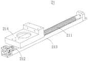
可选地,Y轴移动模组21包括Y轴电机、Y轴丝杆211、Y轴螺母块212以及Y轴滑轨213。Y轴丝杆211连接于Y轴电机,Y轴螺母块212螺纹连接于Y轴丝杆211,Y轴螺母块212同时滑动连接于Y轴滑轨213。Y轴电机可固定于工作底板91上,Y轴丝杆211可通过丝杆座设置于工作底板91上,Y轴滑轨213也固定于工作底板91上。Y轴电机工作时,Y轴丝杆211旋转、Y轴螺母块212在Y轴滑轨213的导向下沿Y轴移动,从而可以调节测试下在Y轴上的位置。Optionally, the Y-axis moving module 21 includes a Y-axis motor, a Y-axis screw 211 , a Y-axis nut block 212 and a Y-axis slide rail 213 . The Y-axis screw rod 211 is connected to the Y-axis motor, the Y-axis nut block 212 is threadedly connected to the Y-axis screw rod 211 , and the Y-axis nut block 212 is slidably connected to the Y-axis slide rail 213 . The Y-axis motor can be fixed on the workingbase 91 , the Y-axis screw 211 can be set on the workingbase 91 through the screw seat, and the Y-axis slide rail 213 is also fixed on the workingbase 91 . When the Y-axis motor works, the Y-axis screw 211 rotates and the Y-axis nut block 212 moves along the Y-axis under the guidance of the Y-axis slide rail 213, so that the position on the Y-axis under test can be adjusted.

可选地,Y轴螺母块212上固定有梭车214,测试下座固定于梭车214上,梭车214的设置可以使测试座的设置位置更加灵活。Optionally, ashuttle 214 is fixed on the Y-axis nut block 212, and the lower test seat is fixed on theshuttle 214. The setting of theshuttle 214 can make the setting position of the test seat more flexible.

可选地,功能测试机构2的数量可为多个,沿X轴方向并排设置,可以在同一时段内测试多个产品,减少测试抓取机构3的等待时间,提高测试的效率。Optionally, the number offunctional testing mechanisms 2 can be multiple, and they are arranged side by side along the X-axis direction, so that multiple products can be tested in the same period of time, reducing the waiting time of the testing grasping mechanism 3 and improving the testing efficiency.

在本发明的其中一个实施例中,请参阅图9及图10,测试抓取机构3包括第一X轴移动模组31、第一Z轴移动模组、第一抓料组件33、第二X轴移动模组32、第二Z轴移动模组以及第二抓料组件。第一Z轴移动模组连接于第一X轴移动模组31,第一抓料组件33连接于第一Z轴移动模组,第二Z轴移动模组连接于第二X轴移动模组32,第二抓料组件连接于第二Z轴移动模组。如此,第一抓料组件33和第二抓料组件可以在X轴方向和Z方向移动,与可以在Y轴方向移动的料盘入料机构1和良品出料机构5配合,实现产品的抓取和释放。In one embodiment of the present invention, please refer to FIG. 9 and FIG. 10 , the test grasping mechanism 3 includes a firstX-axis moving module 31 , a first Z-axis moving module, a first graspingcomponent 33 , a second TheX-axis moving module 32 , the second Z-axis moving module and the second grabbing component. The first Z-axis moving module is connected to the firstX-axis moving module 31, the firstmaterial grabbing assembly 33 is connected to the first Z-axis moving module, and the second Z-axis moving module is connected to the secondX-axis moving module 32. The second material grabbing assembly is connected to the second Z-axis moving module. In this way, the first grabbingassembly 33 and the second grabbing assembly can move in the X-axis direction and the Z-direction, and cooperate with thetray feeding mechanism 1 and the goodproduct discharging mechanism 5 that can move in the Y-axis direction to realize product grabbing take and release.

在本发明的其中一个实施例中,请参阅图9,补料抓取机构6包括第三X轴移动模组61、第三Z轴移动模组和第三抓料组件,第三Z轴移动模组连接于第三X轴移动模组61,第三抓料组件连接于第三Z轴移动模组。使补料抓取机构6能够从补料传输机构7上抓取良品并装填至良品出料机构5的料盘上。In one embodiment of the present invention, please refer to FIG. 9 , the feeding and grabbingmechanism 6 includes a thirdX-axis moving module 61 , a third Z-axis moving module and a third grabbing component, and the third Z-axis moves The module is connected to the thirdX-axis moving module 61 , and the third grabbing component is connected to the third Z-axis moving module. This enables thereplenishment grabbing mechanism 6 to grab good products from thereplenishment transmission mechanism 7 and load them onto the tray of the goodproduct discharge mechanism 5 .

可选地,第一X轴移动模组31、第二X轴移动模组32、第三X轴移动模组61的结构相同,长度可不相同,可为丝杆传动模组。第一Z轴移动模组、第二Z轴移动模组、第三Z轴移动模组的结构相同,长度可不相同,可为丝杆传动模组。第一抓料组件33、第二抓料组件和第三抓料组件的结构可选为相同,各个抓料组件中吸嘴组件的个数可选为相同,也可选为不相同。Optionally, the firstX-axis moving module 31 , the secondX-axis moving module 32 , and the thirdX-axis moving module 61 have the same structure and different lengths, and can be screw drive modules. The first Z-axis moving module, the second Z-axis moving module, and the third Z-axis moving module have the same structure and different lengths, and can be screw drive modules. The structures of the firstmaterial grabbing assembly 33 , the second material grabbing assembly and the third material grabbing assembly can be optionally the same, and the number of suction nozzle assemblies in each material grabbing assembly can be optionally the same or different.

可选地,功能外观测试一体设备还包括工作底板91和工作支架92,工作支架92固定于工作底板91上。料盘入料机构1、功能测试机构2、补料传输机构7、良品出料机构5以及不良品放置机构8均固定于工作底板91上,第一X轴移动模组31、第二X轴移动模组32、第三X轴移动模组61及外观测试机构4均固定于工作支架92上。请参阅图9,第一X轴移动模组31和第三X轴移动模组61可同轴设置,第二X轴移动模组32与第一X轴移动模组31间隔设置。如此,可以极大地节省布局空间,减小设备所需的体积。Optionally, the integrated device for functional appearance testing further includes awork base 91 and awork support 92 , and thework support 92 is fixed on thework base 91 . Thetray feeding mechanism 1, thefunction testing mechanism 2, the feedingtransmission mechanism 7, the goodproduct discharging mechanism 5 and the defectiveproduct placing mechanism 8 are all fixed on the workingbase plate 91. The firstX-axis moving module 31, the second X-axis The movingmodule 32 , the thirdX-axis moving module 61 and the appearance testing mechanism 4 are all fixed on the workingbracket 92 . Referring to FIG. 9 , the firstX-axis moving module 31 and the thirdX-axis moving module 61 can be arranged coaxially, and the secondX-axis moving module 32 and the firstX-axis moving module 31 are arranged at intervals. In this way, the layout space can be greatly saved, and the required volume of the device can be reduced.

可选地,请参阅图10,第一抓料组件33包括抓料安装板331和吸嘴组件332,抓料安装板331连接于Z轴移动模组32,抓料安装板331可固定于Z轴移动模组32的转接板326上。吸嘴组件332固定于抓料安装板331上,吸嘴组件332的数量可为多个,因此可以一次性抓取和释放多个产品,提高产品的检测效率。可选地,吸嘴组件332的数量可选为与料盘宽度方向上放置的产品数量相同,这样,在第一抓料组件33一次抓取后,即可以将料盘上的一排产品同时取走。更具体地,在抓取产品时,第一Z轴移动模组带动第一抓料组件33下移至预定位置时,吸嘴组件332中的吸嘴气缸3321运动,使吸嘴本体3324下移至与产品接触吸附。Optionally, please refer to FIG. 10 , the first grabbingassembly 33 includes agrabbing mounting plate 331 and asuction nozzle assembly 332 , the grabbing mountingplate 331 is connected to the Z-axis moving module 32 , and thegrabbing mounting plate 331 can be fixed on the Z axis. on the adapter plate 326 of theaxis moving module 32 . Thesuction nozzle assemblies 332 are fixed on thegrabbing mounting plate 331 , and the number ofsuction nozzle assemblies 332 can be multiple, so that multiple products can be grasped and released at one time, thereby improving the detection efficiency of the products. Optionally, the number ofsuction nozzle assemblies 332 can be selected to be the same as the number of products placed in the width direction of the tray, so that after thefirst grab assembly 33 grabs once, a row of products on the tray can be simultaneously take away. More specifically, when grabbing the product, when the first Z-axis moving module drives thefirst grab assembly 33 to move down to a predetermined position, thenozzle cylinder 3321 in thenozzle assembly 332 moves to move thenozzle body 3324 down. until contact with the product adsorption.

可选地,请参阅图10,吸嘴组件332包括吸嘴气缸3321、连接架3322、吸嘴本体3324、吸嘴座3325和缓冲件3323。吸嘴气缸3321固定于抓料安装板331上,连接架3322滑动连接于吸嘴气缸3321的气缸轴,吸嘴本体3324固定连接于连接架3322,而且气缸轴和连接架3322之间弹性连接有缓冲件3323。这样,在吸嘴气缸3321的带动下,吸嘴组件332下移触碰到产品时,缓冲件3323压缩,可以减小对气缸轴的反向推力,避免损坏气缸3321。缓冲件3323可选为弹簧。其中,气缸轴上具有止挡台阶,缓冲件3323套设于气缸轴上,缓冲件3323的一端抵接于止挡台阶上,缓冲件3323的另一端抵接于连接架3322上。连接架3322上开设有滑孔,气缸轴穿过滑孔设置,使得连接架3322滑动连接于气缸轴,可相对气缸轴产生位移,缓冲对气缸轴的推力。连接架3322包括依次连接的第一水平部33221、竖直部33222和第二水平部33223,第一水平部33221上开设有滑孔,吸嘴本体3324固定于第二水平部33223。Optionally, referring to FIG. 10 , thenozzle assembly 332 includes anozzle cylinder 3321 , a connectingframe 3322 , anozzle body 3324 , anozzle seat 3325 and abuffer 3323 . Thesuction nozzle cylinder 3321 is fixed on thegrabbing mounting plate 331, the connectingframe 3322 is slidably connected to the cylinder shaft of thesuction nozzle cylinder 3321, thesuction nozzle body 3324 is fixedly connected to the connectingframe 3322, and the cylinder shaft and the connectingframe 3322 are elastically connected with aBuffer 3323. In this way, driven by thesuction nozzle cylinder 3321, when thesuction nozzle assembly 332 moves down and touches the product, thebuffer member 3323 is compressed, which can reduce the reverse thrust to the cylinder shaft and avoid damage to thecylinder 3321. Thebuffer 3323 can optionally be a spring. The cylinder shaft has a stop step, thebuffer member 3323 is sleeved on the cylinder shaft, one end of thebuffer member 3323 abuts on the stop step, and the other end of thebuffer member 3323 abuts on the connectingframe 3322 . The connectingframe 3322 is provided with a sliding hole, and the cylinder shaft is arranged through the sliding hole, so that the connectingframe 3322 is slidably connected to the cylinder shaft, which can generate displacement relative to the cylinder shaft and buffer the thrust on the cylinder shaft. The connectingframe 3322 includes a firsthorizontal portion 33221 , avertical portion 33222 and a secondhorizontal portion 33223 connected in sequence. The firsthorizontal portion 33221 is provided with a sliding hole, and thenozzle body 3324 is fixed to the secondhorizontal portion 33223 .

其中,吸嘴座3325固定于抓料安装板331上,吸嘴本体3324穿过吸嘴座3325设置,吸嘴座3325的设置可以使吸嘴本体3324上下移动时更加稳定,吸嘴座3325对吸嘴本体3324具有导向作用。吸嘴座3325上开设有轴套孔,轴套孔内设置有轴套,吸嘴本体3324穿过轴套设置。可选地,各个吸嘴本体3324对应穿过的吸嘴座3325可一体成型设置。Among them, thesuction nozzle seat 3325 is fixed on thegrabbing mounting plate 331, thesuction nozzle body 3324 is arranged through thesuction nozzle seat 3325, and the setting of thesuction nozzle seat 3325 can make thesuction nozzle body 3324 move up and down more stably. Thenozzle body 3324 has a guiding function. Thenozzle seat 3325 is provided with a bushing hole, the bushing is provided in the bushing hole, and thenozzle body 3324 is arranged through the bushing. Optionally, thenozzle seat 3325 through which eachnozzle body 3324 passes correspondingly may be integrally formed.

可选地,抓料安装板331上固定有抓料滑轨3326,连接架3322上固定有抓料滑块3327,抓料滑块3327滑动连接于抓料滑轨3326,抓料滑轨3326的长度方向沿Z轴设置,抓料滑轨3326和抓料滑块3327的设置可以对吸嘴组件332的移动进行导向,保证吸嘴组件332上下移动时的稳定性。其中,抓料滑块3327可固定于连接架3322的竖直部33222上。每个吸嘴组件332均对应设置有抓料滑轨3326和抓料滑块3327,或者,所有的吸嘴组件332共用抓料滑轨3326和抓料滑块3327。Optionally, a grabbingslide rail 3326 is fixed on thegrabbing mounting plate 331 , a grabbingslider 3327 is fixed on the connectingframe 3322 , and the grabbingblock 3327 is slidably connected to the grabbingrail 3326 . The length direction is arranged along the Z axis, and the setting of the grabbingslide rail 3326 and the grabbingslider 3327 can guide the movement of thesuction nozzle assembly 332 and ensure the stability of thesuction nozzle assembly 332 when it moves up and down. Wherein, the grabbingslider 3327 can be fixed on thevertical portion 33222 of the connectingframe 3322 . Eachsuction nozzle assembly 332 is correspondingly provided with amaterial grabbing rail 3326 and amaterial grabbing slider 3327 , or all thesuction nozzle assemblies 332 share thematerial grabbing rail 3326 and thematerial grabbing slider 3327 .

可选地,请参阅图10,抓料组件33还包括气管连接器333,气管连接器333固定在抓料安装板331上,用于与吸嘴本体3324连接,为吸嘴本体3324提供气体流通通道,使得在抓取产品时,吸嘴本体3324的端部能够产生负压吸取产品,在释放产品时,吸嘴本体3324的端部能够产生正压吹落产品。Optionally, please refer to FIG. 10 , the grabbingassembly 33 further includes anair pipe connector 333 , and theair pipe connector 333 is fixed on the grabmaterial mounting plate 331 and is used for connecting with thesuction nozzle body 3324 to provide air circulation for thesuction nozzle body 3324 The channel enables the end of thesuction nozzle body 3324 to generate negative pressure to suck the product when grasping the product, and the end of thesuction nozzle body 3324 to generate positive pressure to blow off the product when releasing the product.

在本发明的其中一个实施例中,外观测试机构4设置于良品出料机构5的上方,外观测试机构4包括镜头支架、相机以及光源。镜头支架可固定于工作支架92上。相机固定于镜头支架上,光源用于照亮良品出料机构5上的产品,方便相机对料盘上的产品进行拍照。光源可固定于镜头支架,也可以固定于相机上。具体地,在料盘移动至相机的下方时,相机对料盘进行拍照,并分析拍摄的照片,检查出拍照区域内是否存在漏料、外观瑕疵、产品放反的情况等。In one embodiment of the present invention, the appearance testing mechanism 4 is disposed above the goodproduct discharging mechanism 5, and the appearance testing mechanism 4 includes a lens holder, a camera and a light source. The lens holder can be fixed on the workingholder 92 . The camera is fixed on the lens bracket, and the light source is used to illuminate the products on the goodproduct discharging mechanism 5, which is convenient for the camera to take pictures of the products on the feeding tray. The light source can be fixed on the lens holder or on the camera. Specifically, when the tray moves to the bottom of the camera, the camera takes a picture of the tray, analyzes the photographed photos, and checks whether there is material leakage, appearance defects, and reversed products in the photographed area.

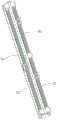
在本发明的其中一个实施例中,请参阅图11,补料传输机构7设置于良品出料机构5的一侧,补料传输机构7包括补料电机71、补料丝杆72、补料螺母块73、补料滑块74以及补料滑轨73。补料电机71驱动补料丝杆72旋转,补料螺母块73螺纹连接于补料丝杆72,补料滑块74滑动连接于补料滑轨75,用于对补料滑块74进行导向,补料盘放置在补料螺母块73上,随补料螺母块73沿Y轴移动。在与补料抓取机构6相正对的一排产品取完后,补料电机71带动补料盘沿Y轴移动,使产品移动至与补料抓取机构6相正对。In one embodiment of the present invention, please refer to FIG. 11 , the feedingtransmission mechanism 7 is arranged on one side of the goodproduct discharging mechanism 5 , and thefeeding transmission mechanism 7 includes a feedingmotor 71 , a feedingscrew 72 , afeeding Nut block 73 , feedingslider 74 andfeeding sliding rail 73 . The feedingmotor 71 drives the feedingscrew 72 to rotate, the feedingnut block 73 is threadedly connected to the feedingscrew 72, and thefeeding sliding block 74 is slidably connected to thefeeding sliding rail 75 for guiding thefeeding sliding block 74. , the feeding tray is placed on the feedingnut block 73 and moves along the Y axis with the feedingnut block 73 . After a row of products opposite to thefeeding grabbing mechanism 6 is taken, the feedingmotor 71 drives the feeding tray to move along the Y axis, so that the products are moved to be opposite to thefeeding grabbing mechanism 6 .

可选地,不良品放置机构8可与补料传输机构7的结构相同,也通过丝杆传动,且其传动方向为Y轴方向,不良品放置机构8的具体结构此处不作赘述。Optionally, the defectiveproduct placement mechanism 8 may have the same structure as the feedingtransmission mechanism 7, and is also driven by a screw rod, and its transmission direction is the Y-axis direction. The specific structure of the defectiveproduct placement mechanism 8 will not be repeated here.

以上所述仅为本发明的较佳实施例而已,并不用以限制本发明,凡在本发明的精神和原则之内所作的任何修改、等同替换和改进等,均应包含在本发明的保护范围之内。The above descriptions are only preferred embodiments of the present invention and are not intended to limit the present invention. Any modifications, equivalent replacements and improvements made within the spirit and principles of the present invention shall be included in the protection of the present invention. within the range.

Claims (10)

Translated fromChinese
1.一种功能外观一体测试设备,其特征在于,包括:1. a functional appearance integrated test equipment, is characterized in that, comprises:料盘入料机构,用于运输装载有待检测产品的料盘,所述料盘入料机构的传输方向沿Y轴设置;The feeding tray feeding mechanism is used to transport the feeding tray loaded with the product to be tested, and the transmission direction of the feeding tray feeding mechanism is set along the Y axis;功能测试机构,用于对产品进行功能测试;Functional testing agency for functional testing of products;测试抓取机构,用于从所述料盘入料机构上的料盘中抓取产品并移动至所述功能测试机构,并将检测完成的良品移动至良品出料机构以及将检测完成的不良品移动至不良品放置机构;The test grabbing mechanism is used to grab the product from the tray on the tray feeding mechanism and move it to the functional testing mechanism, and move the inspected good products to the good product discharge mechanism and the inspected defective products. The good product is moved to the bad product placement mechanism;外观测试机构,用于确认产品的数量、检查产品的外观和放置方向;Appearance testing agency to confirm the quantity of the product, check the appearance and placement direction of the product;良品出料机构,用于运输装载有良品的料盘,所述良品出料机构的传输方向沿Y轴设置;The good product discharging mechanism is used to transport the tray loaded with good products, and the transmission direction of the good product discharging mechanism is set along the Y axis;补料抓取机构,用于将所述良品出料机构中外观不良和放置方向错误的产品移动至所述不良品放置机构,并装填良品;The feeding and grabbing mechanism is used to move the products with poor appearance and wrong placement direction in the good product discharging mechanism to the defective product placement mechanism, and fill the good products;补料传输机构,为所述补料抓取机构提供良品;以及a feeding transfer mechanism to provide good products for the feeding grabbing mechanism; and不良品放置机构,用于放置功能不良品、外观不良和放置方向错误的产品。The defective product placement mechanism is used to place defective functional products, products with poor appearance and wrong placement.2.如权利要求1所述的功能外观一体测试设备,其特征在于,所述料盘入料机构、所述功能测试机构、所述良品出料机构、所述不良品放置机构沿X轴方向依次排列设置。2 . The function-appearance integrated testing device according to claim 1 , wherein the tray feeding mechanism, the functional testing mechanism, the good product discharging mechanism, and the defective product placing mechanism are along the X-axis direction. 3 . Arrange the settings in order.3.如权利要求2所述的功能外观一体测试设备,其特征在于,所述补料传输机构的传输方向沿Y轴设置,且所述补料传输机构设于所述功能测试机构和所述良品出料机构之间。3. The function-appearance integrated testing device according to claim 2, wherein the transmission direction of the feed transmission mechanism is arranged along the Y-axis, and the feed transmission mechanism is provided in the functional test mechanism and the Good product delivery agencies.4.如权利要求1所述的功能外观一体测试设备,其特征在于,所述测试抓取机构包括第一X轴移动模组、连接于所述第一X轴移动模组的第一Z轴移动模组、连接于所述第一Z轴移动模组的第一抓料组件、第二X轴移动模组、连接于所述第二X轴移动模组的第二Z轴移动模组、连接于所述第二Z轴移动模组的第二抓料组件,所述第一抓料组件用于从所述料盘入料机构上的料盘中抓取产品并移动至所述功能测试机构,所述第二抓料组件用于将检测完成的良品移动至所述良品出料机构以及将检测出的不良品移动至所述不良品放置机构。4. The function-appearance integrated testing device according to claim 1, wherein the test grasping mechanism comprises a first X-axis moving module, a first Z-axis connected to the first X-axis moving module a moving module, a first grabbing component connected to the first Z-axis moving module, a second X-axis moving module, a second Z-axis moving module connected to the second X-axis moving module, The second material grabbing component connected to the second Z-axis moving module, the first material grabbing component is used to grab the product from the material tray on the material tray feeding mechanism and move it to the functional test The second material grabbing assembly is used for moving the detected good products to the good product discharging mechanism and moving the detected defective products to the defective product placement mechanism.5.如权利要求4所述的功能外观一体测试设备,其特征在于,所述补料抓取机构包括第三X轴移动模组、连接于所述第三X轴移动模组的第三Z轴移动模组以及连接于所述第三Z轴移动模组的第三抓料组件。5. The function-appearance integrated testing device according to claim 4, wherein the feeding and grabbing mechanism comprises a third X-axis moving module, a third Z-axis connected to the third X-axis moving module an axis moving module and a third grabbing component connected to the third Z-axis moving module.6.如权利要求5所述的功能外观一体测试设备,其特征在于,所述功能外观一体测试设备还包括工作底板以及固定于所述工作底板上的工作支架,所述料盘入料机构、所述功能测试机构、所述补料传输机构、所述良品出料机构以及所述不良品放置机构均固定于所述工作底板上,所述第一X轴移动模组、所述第二X轴移动模组、所述第三X轴移动模组及所述外观测试机构均固定于所述工作支架上。6. The integrated function and appearance test equipment according to claim 5, wherein the integrated function and appearance test equipment further comprises a working base plate and a working bracket fixed on the working base plate, the tray feeding mechanism, The functional testing mechanism, the feeding transmission mechanism, the good product discharging mechanism, and the defective product placing mechanism are all fixed on the working bottom plate, the first X-axis moving module, the second X-axis moving module, and the The axis moving module, the third X-axis moving module and the appearance testing mechanism are all fixed on the working bracket.7.如权利要求1所述的功能外观一体测试设备,其特征在于,所述功能测试机构包括Y轴移动模组、由所述Y轴移动模组驱动的测试下座、测试升降组件、以及由所述测试升降组件驱动且用于下压所述测试下座的测试上座。7. The function-appearance integrated testing device according to claim 1, wherein the functional testing mechanism comprises a Y-axis moving module, a test lower seat driven by the Y-axis moving module, a test lifting assembly, and A test upper seat driven by the test lift assembly and used to press down the test lower seat.8.如权利要求1所述的功能外观一体测试设备,其特征在于,所述料盘入料机构包括:8. The function-appearance integrated testing device according to claim 1, wherein the tray feeding mechanism comprises:料盘分层机构,包括用于升降堆叠的料盘的第一升降组件以及用于分离最底层料盘和其他料盘的第一承托组件;A material tray layering mechanism, including a first lifting component for lifting and stacking the material trays and a first supporting component for separating the bottommost material tray and other material trays;料盘移动机构,用于输送从所述料盘分层机构中分离出的料盘;以及a tray moving mechanism for conveying the trays separated from the tray layering mechanism; and料盘堆叠机构,用于堆叠经过所述料盘移动机构运输的料盘,所述料盘堆叠机构包括用于支撑堆叠料盘的第二承托组件以及用于将所述料盘移动机构上的料盘推顶至堆叠料盘的底部的第二升降组件。A tray stacking mechanism for stacking trays transported by the tray moving mechanism, the tray stacking mechanism comprising a second supporting component for supporting the stacked trays and a tray for moving the tray on the tray A second lift assembly that pushes the tray to the bottom of the stack tray.9.如权利要求8所述的功能外观一体测试设备,其特征在于,所述料盘移动机构包括传输驱动件、由所述传输驱动件驱动且用于放置料盘的承载盘、用于将料盘卡紧于所述承载盘中的卡紧组件以及用于导向料盘的导轨结构。9 . The function-appearance integrated testing device according to claim 8 , wherein the material tray moving mechanism comprises a transmission driving member, a carrier plate driven by the transmission driving member and used for placing the material tray, and used for placing the material tray. 10 . The material tray is clamped to the clamping component in the carrying tray and the guide rail structure for guiding the material tray.10.如权利要求9所述的功能外观一体测试设备,其特征在于,所述卡紧组件包括固定于所述承载盘的钩爪气缸、连接于所述钩爪气缸输出端且用于卡紧固定料盘的钩爪本体以及使所述钩爪本体转动连接于所述承载盘的钩爪销。10 . The integrated function and appearance testing device according to claim 9 , wherein the clamping component comprises a hook cylinder fixed on the carrier plate, connected to the output end of the hook cylinder and used for clamping. 11 . The hook body of the fixed material tray and the hook pin that makes the hook body rotatably connect to the carrying tray.
CN202011058064.9A2020-09-302020-09-30 Functional and appearance integrated testing equipmentActiveCN112122146B (en)

Priority Applications (1)

Application NumberPriority DateFiling DateTitle
CN202011058064.9ACN112122146B (en)2020-09-302020-09-30 Functional and appearance integrated testing equipment

Applications Claiming Priority (1)

Application NumberPriority DateFiling DateTitle
CN202011058064.9ACN112122146B (en)2020-09-302020-09-30 Functional and appearance integrated testing equipment

Publications (2)

Publication NumberPublication Date
CN112122146Atrue CN112122146A (en)2020-12-25
CN112122146B CN112122146B (en)2025-03-14

Family

ID=73843353

Family Applications (1)

Application NumberTitlePriority DateFiling Date
CN202011058064.9AActiveCN112122146B (en)2020-09-302020-09-30 Functional and appearance integrated testing equipment

Country Status (1)

CountryLink
CN (1)CN112122146B (en)

Cited By (5)

* Cited by examiner, † Cited by third party
Publication numberPriority datePublication dateAssigneeTitle
CN112858094A (en)*2021-01-152021-05-28四川同人精工科技有限公司Automatic control method and system for core density measuring device
CN112858095A (en)*2021-01-152021-05-28四川同人精工科技有限公司Core density measuring device
CN113245245A (en)*2021-04-302021-08-13惠州市指南测控技术有限公司Full-automatic test equipment of bluetooth headset
CN114749385A (en)*2022-03-302022-07-15苏州威达智电子科技有限公司Automatic product loading and unloading cartridge clip, detection system and detection method
CN115582282A (en)*2022-12-132023-01-10赫比(苏州)通讯科技有限公司Automatic connection inspection equipment and use method thereof

Citations (4)

* Cited by examiner, † Cited by third party
Publication numberPriority datePublication dateAssigneeTitle
KR101849495B1 (en)*2017-06-162018-04-16박준우Checking and sorting machine for automobile parts
CN108296179A (en)*2018-02-102018-07-20深圳市海铭德科技有限公司A kind of remote controler product automation test picking method and device
CN111589723A (en)*2020-05-252020-08-28厦门攸信信息技术有限公司 A kind of magnet dispensing effect detection equipment
CN213558490U (en)*2020-09-302021-06-29昆山晔芯电子科技有限公司Integrative test equipment of function outward appearance

Patent Citations (4)

* Cited by examiner, † Cited by third party
Publication numberPriority datePublication dateAssigneeTitle
KR101849495B1 (en)*2017-06-162018-04-16박준우Checking and sorting machine for automobile parts
CN108296179A (en)*2018-02-102018-07-20深圳市海铭德科技有限公司A kind of remote controler product automation test picking method and device
CN111589723A (en)*2020-05-252020-08-28厦门攸信信息技术有限公司 A kind of magnet dispensing effect detection equipment
CN213558490U (en)*2020-09-302021-06-29昆山晔芯电子科技有限公司Integrative test equipment of function outward appearance

Cited By (6)

* Cited by examiner, † Cited by third party
Publication numberPriority datePublication dateAssigneeTitle
CN112858094A (en)*2021-01-152021-05-28四川同人精工科技有限公司Automatic control method and system for core density measuring device
CN112858095A (en)*2021-01-152021-05-28四川同人精工科技有限公司Core density measuring device
CN113245245A (en)*2021-04-302021-08-13惠州市指南测控技术有限公司Full-automatic test equipment of bluetooth headset
CN114749385A (en)*2022-03-302022-07-15苏州威达智电子科技有限公司Automatic product loading and unloading cartridge clip, detection system and detection method
CN115582282A (en)*2022-12-132023-01-10赫比(苏州)通讯科技有限公司Automatic connection inspection equipment and use method thereof
CN115582282B (en)*2022-12-132023-03-10赫比(苏州)通讯科技有限公司Automatic wiring inspection equipment and use method thereof

Also Published As

Publication numberPublication date
CN112122146B (en)2025-03-14

Similar Documents

PublicationPublication DateTitle
CN112122146A (en) Function and appearance integrated test equipment
CN1873423B (en)Electronic element automatic moving loader
CN112246663B (en) Product counting device and chip testing equipment
JP3016982B2 (en) Apparatus and method for handling tray of automatic test handler
WO2023071319A1 (en)Stacked tray separating and feeding apparatus
CN105382551B (en) An automatic production line for smart watches
CN212944180U (en)Automatic test equipment for electronic element
CN205309782U (en) An automatic production line for smart watches
CN111977348A (en) Product inspection and automatic refilling machine
CN112141706A (en)Product grabbing device and chip test equipment
CN117644044A (en)Automatic detection system for appearance of flexible board
CN110615247A (en)Integrated automatic material taking and placing mechanism
CN213149190U (en)Automatic battery detection equipment
CN213792877U (en)Product counting device and chip testing equipment
CN210914300U (en) An automatic feeding mechanism
CN106623001A (en) An automatic pre-charging and testing equipment
CN213558490U (en)Integrative test equipment of function outward appearance
CN108318712A (en)Automatic detection equipment
CN118263173A (en)Cover-removing feeding and discharging device and method and semiconductor chip detection sorting machine
CN219620288U (en)Feeding and discharging mechanism and double-sided product detection device
CN117440147A (en) A multi-position test equipment for camera modules
CN216736015U (en)Feeding device for multilayer material tray
CN116477347A (en) A kind of image sensor test equipment
CN109205290B (en)Function test equipment
CN220547302U (en)Screening device

Legal Events

DateCodeTitleDescription
PB01Publication
PB01Publication
SE01Entry into force of request for substantive examination
CB02Change of applicant information

Address after:215300 No. 188, Jinshun Road, Jinxi Town, Kunshan City, Suzhou City, Jiangsu Province

Applicant after:Kunshan sitewei integrated circuit Co.,Ltd.

Address before:No. 338, Jinshun Road, Jinxi Town, Kunshan City, Suzhou City, Jiangsu Province

Applicant before:KUNSHAN YEXIN ELECTRONIC TECHNOLOGY Co.,Ltd.

CB02Change of applicant information
GR01Patent grant
GR01Patent grant

[8]ページ先頭

©2009-2025 Movatter.jp