CN112120831A - A clamp with expandable arms - Google Patents
A clamp with expandable armsDownload PDFInfo
- Publication number
- CN112120831A CN112120831ACN202011051160.0ACN202011051160ACN112120831ACN 112120831 ACN112120831 ACN 112120831ACN 202011051160 ACN202011051160 ACN 202011051160ACN 112120831 ACN112120831 ACN 112120831A
- Authority
- CN
- China
- Prior art keywords
- clamp
- plate
- clamping
- assembly
- base
- Prior art date
- Legal status (The legal status is an assumption and is not a legal conclusion. Google has not performed a legal analysis and makes no representation as to the accuracy of the status listed.)
- Pending
Links
Images


Classifications
- A—HUMAN NECESSITIES
- A61—MEDICAL OR VETERINARY SCIENCE; HYGIENE
- A61F—FILTERS IMPLANTABLE INTO BLOOD VESSELS; PROSTHESES; DEVICES PROVIDING PATENCY TO, OR PREVENTING COLLAPSING OF, TUBULAR STRUCTURES OF THE BODY, e.g. STENTS; ORTHOPAEDIC, NURSING OR CONTRACEPTIVE DEVICES; FOMENTATION; TREATMENT OR PROTECTION OF EYES OR EARS; BANDAGES, DRESSINGS OR ABSORBENT PADS; FIRST-AID KITS
- A61F2/00—Filters implantable into blood vessels; Prostheses, i.e. artificial substitutes or replacements for parts of the body; Appliances for connecting them with the body; Devices providing patency to, or preventing collapsing of, tubular structures of the body, e.g. stents
- A61F2/02—Prostheses implantable into the body
- A61F2/24—Heart valves ; Vascular valves, e.g. venous valves; Heart implants, e.g. passive devices for improving the function of the native valve or the heart muscle; Transmyocardial revascularisation [TMR] devices; Valves implantable in the body
- A61F2/2442—Annuloplasty rings or inserts for correcting the valve shape; Implants for improving the function of a native heart valve
- A61F2/2466—Delivery devices therefor
Landscapes
- Health & Medical Sciences (AREA)
- Cardiology (AREA)
- Oral & Maxillofacial Surgery (AREA)
- Transplantation (AREA)
- Engineering & Computer Science (AREA)
- Biomedical Technology (AREA)
- Heart & Thoracic Surgery (AREA)
- Vascular Medicine (AREA)
- Life Sciences & Earth Sciences (AREA)
- Animal Behavior & Ethology (AREA)
- General Health & Medical Sciences (AREA)
- Public Health (AREA)
- Veterinary Medicine (AREA)
- Prostheses (AREA)
Abstract
Description
Translated fromChinese技术领域technical field
本发明涉及医疗器械领域,尤其涉及一种带可扩张臂的夹合器。The invention relates to the field of medical instruments, in particular to a clamp with an expandable arm.
背景技术Background technique
二尖瓣即左房室瓣,又称“僧帽瓣”,附于左纤维房室环上。正常的二尖瓣由瓣环、瓣叶、腱索、乳头肌组成,二尖瓣功能的完整性要求二尖瓣瓣环大小合适,瓣叶结构完整,乳头肌收缩牵拉腱索发挥瓣叶的支撑作用,左心室肌肉收缩产生关闭力量适当,心室形态及功能正常。这些因素共同决定着二尖瓣的完整性,任何一个因素出现异常都会导致二尖瓣反流。所以二尖瓣反流(Mitral regurgitation,简称MR)是最常见的心脏瓣膜疾病。The mitral valve is the left atrioventricular valve, also known as the mitral valve, attached to the left fibrous atrioventricular annulus. A normal mitral valve is composed of annulus, leaflets, chordae tendineae, and papillary muscles. The integrity of mitral valve function requires that the size of the mitral valve annulus is appropriate, the valve leaflet structure is complete, and the papillary muscles contract and stretch the chordae tendineae to exert the valve leaflets. The supporting effect of left ventricular muscle contraction produces appropriate closing force, and the shape and function of the ventricle are normal. These factors together determine the integrity of the mitral valve, and any abnormality in any one of these factors can lead to mitral regurgitation. Therefore, mitral regurgitation (MR) is the most common heart valve disease.
近年来,随着科技的发展,国内外器械厂家研制出一批用于治疗二尖瓣反流的介入器械。相应的治疗或修复技术主要有缘对缘修复技术、瓣环环缩技术、瓣环成形术、腱索置入技术等。其中缘对缘修复技术历史悠久,安全性更好,现阶段领跑于修复的其他技术,其中雅培MitraClip和爱德华PASCAL为典型的代表。MitraClip的介入器械由于输送鞘管限制,夹合范围太小,故需要多个夹子(两个以上),使得临床使用时经常使用多个夹子才能起到良好效果,导致操作复杂,这给增加了手术难度并提高了手术风险,也增加医疗费用。In recent years, with the development of science and technology, domestic and foreign device manufacturers have developed a batch of interventional devices for the treatment of mitral regurgitation. Corresponding treatment or repair techniques mainly include edge-to-edge repair technique, annulus retraction technique, annuloplasty, chorda tendinea insertion technique, etc. Among them, edge-to-edge repair technology has a long history and better safety. At this stage, it leads other repair technologies, among which Abbott MitraClip and Edward PASCAL are typical representatives. Due to the limitation of the delivery sheath, the interventional device of MitraClip requires multiple clips (more than two), so that multiple clips are often used in clinical use to achieve good results, resulting in complicated operations, which increases the number of clips. Surgery is difficult and increases the risk of surgery, but also increases medical costs.
发明内容SUMMARY OF THE INVENTION
为了克服现有技术的不足,本发明的目的在于降低二尖瓣手术难度和风险的新型辅助器械,具体提供一种带可扩张臂的夹合器,其能解决传统夹合器结构复杂且存在两侧反流泄露的问题。In order to overcome the deficiencies of the prior art, the purpose of the present invention is to reduce the difficulty and risk of mitral valve surgery, a new type of auxiliary device, specifically to provide a clamp with an expandable arm, which can solve the complex structure of the traditional clamp and the existence of The problem of reflux leakage on both sides.
本发明的目的采用以下技术方案实现。The purpose of the present invention is achieved by the following technical solutions.
一种带可扩张臂的夹合器,所述夹合器包括上夹组件、下夹组件、底座、锁定机构和扩张臂;所述上夹组件和下夹组件数量相等且开合匹配形成夹合部;所述底座包括底座体和底座支杆,所述底座支杆垂直的设置在所述底座体的上表面;所述锁定机构活动的套接所述底座支杆上并且底部抵接支撑至所述底座体的上表面;所述上夹组件下部固定设置在所述锁定机构的一个侧面上,所述下夹组件活动连接至所述锁定机构且位于所述上夹组件的下方;所述扩张臂可拆卸的设置在所述下夹组件上部,向下夹组件的夹合底板两侧方向延伸;当上夹组件与下夹组件呈工作夹合状态时,所述扩张臂扩张外缘处于相邻或相对的两个下夹组件之间对夹合部两侧的瓣膜进行夹合,以增加夹合范围;所述扩张臂具有变形性,在输送时呈压缩状态,使得夹合器整体压缩进输送系统,减少手术时的损伤。A clamp with an expandable arm, the clamp includes an upper clamp assembly, a lower clamp assembly, a base, a locking mechanism and an expansion arm; the upper clamp assembly and the lower clamp assembly are equal in number and open and close to form a clamp The base includes a base body and a base support rod, the base support rod is vertically arranged on the upper surface of the base body; the locking mechanism is movably sleeved on the base support rod and the bottom is abutted and supported to the upper surface of the base body; the lower part of the upper clip assembly is fixedly arranged on one side of the locking mechanism, and the lower clip assembly is movably connected to the locking mechanism and is located below the upper clip assembly; The expansion arm is detachably arranged on the upper part of the lower clamp assembly, and extends in both sides of the clamping bottom plate of the lower clamp assembly; when the upper clamp assembly and the lower clamp assembly are in a working clamping state, the expansion arm expands the outer edge The valves on both sides of the clamping part are clamped between two adjacent or opposite lower clamp assemblies to increase the clamping range; the expansion arm is deformable and is in a compressed state during delivery, so that the clamp is in a state of compression. The whole is compressed into the delivery system to reduce the damage during surgery.
优选的,所述上夹组件包括具有形状记忆功能的弹性上夹板,在所述弹性上夹板的板体上开设至少一个穿线孔,在所述弹性上夹板的面向所述下夹组件的一面上设有粗糙结构,所述粗糙结构包括齿状结构、倒刺结构或凸起结构。Preferably, the upper clamp assembly includes an elastic upper clamp plate with a shape memory function, at least one threading hole is opened on the plate body of the elastic upper clamp plate, and on the side of the elastic upper clamp plate facing the lower clamp assembly A rough structure is provided, the rough structure includes a tooth-like structure, a barb structure or a raised structure.
优选的,所述上夹组件还包括上夹连接底板,在所述上夹连接底板的两端分别设置一个所述弹性上夹板,所述上夹连接底板和两端的弹性上夹板一体的设置呈凹型结构,且在所述上夹连接底板的中间开设上夹贯通孔,在两个所述弹性上夹板的下部贯通的开设上夹导向限位孔,上夹导向限位孔在上夹热处理成型工艺过程中起应力释放作用;所述上夹连接底板的上表面与所述锁定机构的底面贴合设置,两个所述弹性上夹板的下部内侧面与所述锁定机构的外侧面贴合设置。Preferably, the upper clip assembly further comprises an upper clip connection bottom plate, and one elastic upper clip plate is respectively provided at both ends of the upper clip connection bottom plate, and the upper clip connection bottom plate and the elastic upper clip plates at both ends are integrally arranged in the form of a single piece. The upper clip has a concave structure, and an upper clip through hole is opened in the middle of the upper clip connecting bottom plate, and an upper clip guide limit hole is formed through the lower part of the two elastic upper clip plates, and the upper clip guide limit hole is formed by heat treatment on the upper clip It plays a role in stress relief during the process; the upper surface of the upper clip connecting base plate is fitted with the bottom surface of the locking mechanism, and the inner sides of the lower parts of the two elastic upper clamping plates are fitted with the outer side of the locking mechanism. .
优选的,具有形状记忆功能的弹性上夹板具有预设扩张角α,且α=30~135°。Preferably, the elastic upper splint with shape memory function has a preset expansion angle α, and α=30-135°.
优选的,所述下夹组件包括下夹底板和位于下夹底板两侧垂直设置的下夹侧板,由所述下夹底板和下夹侧板形成与上夹组件配合的容纳槽腔;Preferably, the lower clip assembly includes a lower clip bottom plate and a lower clip side plate vertically disposed on both sides of the lower clip bottom plate, and the lower clip bottom plate and the lower clip side plate form a accommodating cavity matched with the upper clip assembly;
所述下夹侧板的下部连接外扩板和铰接板,通过外扩后的铰接板活动的连接至所述锁定机构上。The lower part of the lower clip side plate is connected with the outer expansion plate and the hinge plate, and is movably connected to the locking mechanism through the outer expansion hinge plate.
优选的,在所述铰接板上贯通的开设铰接孔用于下夹组件与锁定机构的连接;在所述外扩板上开设联动孔。Preferably, a hinge hole is formed through the hinge plate for connecting the lower clip assembly with the locking mechanism; a linkage hole is formed on the outer expansion plate.
优选的,在所述下夹底板和下夹侧板的上边沿内侧做圆角处理或向外圆弧延伸的翻边。Preferably, the inner side of the upper edge of the lower clip bottom plate and the lower clip side plate is rounded or flanged with an outward arc.
优选的,所述锁定机构包括锁定座,所述锁定座的下部开设中空的锁定容纳腔,在所述锁定容纳腔的一个侧壁上向腔内突出设置斜面凸台,所述斜面凸台用于嵌合所述底座支杆以使得锁定机构定位在所述底座上。Preferably, the locking mechanism includes a locking seat, a lower part of the locking seat is provided with a hollow locking accommodating cavity, and a sloped boss is protruded into the cavity on one side wall of the locking accommodating cavity, and the sloped boss is used for Fitting the base support rod so that the locking mechanism is positioned on the base.
优选的,所述扩张臂包括条状或管状的扩张外框,所述扩张臂形式采用包括但不限于半圆环形、两半环连接的ω形、两非规则曲形对接半环形、两对接的梯形、或U形中的一种。Preferably, the expansion arm comprises a strip-shaped or tubular expansion frame, and the expansion arm forms include, but are not limited to, a semi-circular ring, an omega-shaped connecting two half-rings, two irregular curved butt-jointed semi-rings, two One of the trapezoid or U shape.
优选的,在所述扩张臂的扩张外框的内凹处设置封堵编网。Preferably, a blocking braided net is arranged at the inner recess of the expansion frame of the expansion arm.
优选的,所述扩张臂的封堵编网的孔隙小于反流体的外径。Preferably, the pores of the plugging mesh of the expansion arm are smaller than the outer diameter of the counter fluid.
优选的,所述上夹组件包括两个弹性上夹板并相对的设置在所述锁定机构两侧,相应的设置两个下夹组件。Preferably, the upper clamp assembly includes two elastic upper clamp plates, which are arranged on both sides of the locking mechanism opposite to each other, and two lower clamp assemblies are correspondingly arranged.
优选的,所述扩张臂与所述下夹组件连接,连接方式包括但不限于插接、铆接、焊接、或螺纹连接;其中,所述扩张臂是具有形状记忆功能的合金或可降解高分子材料。Preferably, the expansion arm is connected to the lower clip assembly, and the connection methods include but are not limited to plug-in, riveting, welding, or screw connection; wherein, the expansion arm is an alloy with shape memory function or a degradable polymer Material.
优选的,所述合金包括但不限于具有形状记忆功能的镍钛合金、镁合金,所述高分子材料包括可降解左旋聚合乳酸。Preferably, the alloy includes but is not limited to nickel-titanium alloy and magnesium alloy with shape memory function, and the polymer material includes degradable L-lactic acid.
优选的,所述粗糙结构为从所述弹性上夹板板体的两个侧边斜向形成的锯齿排或倒刺排,或者是两侧连续为一整条的锯齿排结构。Preferably, the rough structure is a zigzag row or barb row formed obliquely from two sides of the elastic upper splint body, or a zigzag row structure whose two sides are continuous as a whole.
优选的,夹合器还包括连杆臂,所述连杆臂包括连杆底板和垂直于连杆底板侧边垂直设置的连杆侧板,所述连杆侧板的下部活动的连接在所述底座的底座体上,所述连杆侧板的上部活动的连接在所述下夹组件的联动孔处,以此形成四连杆联动机构,且由连杆底板和连杆侧板形成的容纳凹槽与所述下夹组件的下部外轮廓容纳匹配。Preferably, the clamp further includes a link arm, the link arm includes a link base plate and a link side plate perpendicular to the side of the link base plate, and the lower part of the link side plate is movably connected to the On the base body of the base, the upper part of the connecting rod side plate is movably connected to the linkage hole of the lower clamp assembly, thereby forming a four-link linkage mechanism, and the connecting rod bottom plate and the connecting rod side plate are formed. The accommodating groove is accommodating and matching with the lower outer contour of the lower clip assembly.
优选的,在所述上夹组件、下夹组件、底座、锁定机构和扩张臂的外表面涂覆生物相容性PET覆膜。Preferably, a biocompatible PET film is coated on the outer surfaces of the upper clip assembly, the lower clip assembly, the base, the locking mechanism and the expansion arm.
相比现有技术,本发明的有益效果在于:本夹合器带有结构简单的扩张臂,扩张臂与夹合器可拆装也可一体的设置。同时,可扩张臂具有变形性,在输送状态可以压缩变小,使得夹合器能整体压缩进更小输送系统,减少手术时损伤。上夹组件易于单独控制捕获瓣叶,降低捕获过程对于瓣叶伤害。当上夹组件与下夹组件夹合时周边扩张臂对夹合部两侧的瓣膜进行夹合,增加了夹合范围,提高手术成功率,以及减少多个夹子使用的概率。该器械可以通过经股静脉穿房间隔入路,用于治疗二尖瓣反流或三尖瓣反流,具有微创介入优点。Compared with the prior art, the beneficial effect of the present invention is that the clamp has an expansion arm with a simple structure, and the expansion arm and the clamp can be disassembled or integrally arranged. At the same time, the expandable arm is deformable and can be compressed to become smaller in the delivery state, so that the clamp can be compressed into a smaller delivery system as a whole, thereby reducing damage during surgery. The upper clip assembly is easy to control the capture valve leaflet individually, reducing the damage to the valve leaflet during the capture process. When the upper clip assembly and the lower clip assembly are clamped, the peripheral expansion arm clamps the valves on both sides of the clamping portion, which increases the clamping range, improves the success rate of surgery, and reduces the probability of using multiple clamps. The device can be used to treat mitral regurgitation or tricuspid regurgitation through a transatrial septal approach through the femoral vein, and has the advantages of minimally invasive intervention.
附图说明Description of drawings
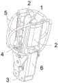
图1为本发明带扩张臂的夹合器结构示意图;Fig. 1 is the structural schematic diagram of the clamper with expansion arm of the present invention;
图2为图1的正视图;Fig. 2 is the front view of Fig. 1;
图3为夹合器的部分结构示意图;Fig. 3 is the partial structure schematic diagram of the clamp;
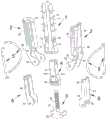
图4为带半圆环形扩张臂的夹合器部分结构分解示意图;4 is a schematic exploded view of the partial structure of the clamp with a semi-circular annular expansion arm;
图5为底座仰视图;Figure 5 is a bottom view of the base;
图6为上夹组件打开接近90°状态示意图;Fig. 6 is a schematic diagram of the state in which the upper clip assembly is opened and close to 90°;
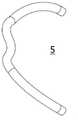
图7为两半环连接的ω形的扩张臂示意图;7 is a schematic diagram of an ω-shaped expansion arm connected by two half-rings;
图8为两对接的梯形扩张臂示意图;8 is a schematic diagram of two butt-jointed trapezoidal expansion arms;
图9为两非规则曲形对接半环形的扩张臂示意图;9 is a schematic diagram of two irregularly curved butt-jointed expanding arms;
图10为半圆环形扩张臂内设封堵编网的示意图;Fig. 10 is the schematic diagram that the blocking weaving net is arranged in the semi-circular annular expansion arm;
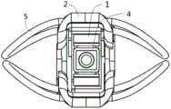
图11为带扩张臂的夹合器原始状态俯视示意图;Figure 11 is a schematic top view of the original state of the clamp with the expansion arm;
图12为带扩张臂的夹合器呈压缩状态的俯视示意图;Figure 12 is a schematic top view of the clamp with expansion arm in a compressed state;
图13为可扩张臂增加捕获面积的示意图。Figure 13 is a schematic diagram of the expandable arm increasing the capture area.
具体实施方式Detailed ways
为使本发明实施例的目的、技术方案和优点更加清楚,下面将结合本发明实施例中的附图,对本发明实施例中的技术方案进行清楚、完整地描述,显然,所描述的实施例是本发明的一部分实施例,而不是全部的实施例。基于本发明中的实施例,本领域普通技术人员在没有做出创造性劳动的前提下所获得的所有其他实施例,都属于本发明保护的范围。In order to make the purposes, technical solutions and advantages of the embodiments of the present invention clearer, the technical solutions in the embodiments of the present invention will be clearly and completely described below with reference to the accompanying drawings in the embodiments of the present invention. Obviously, the described embodiments These are some embodiments of the present invention, but not all embodiments. Based on the embodiments of the present invention, all other embodiments obtained by those of ordinary skill in the art without creative work fall within the protection scope of the present invention.
一种带可扩张臂的夹合器,参见图1-图13,夹合器包括上夹组件1、下夹组件2、底座3、锁定机构4、扩张臂5和连杆臂6,其用于治疗二尖瓣反流或三尖瓣反流。A clamp with an expandable arm, see Figures 1-13, the clamp includes an
其中,下夹组件2、底座3、锁定机构4、和连杆臂6构成四连杆机构,使得瓣膜夹合器的开合更易操作。Among them, the
其中,所述上夹组件1和下夹组件2数量相等且开合匹配形成夹合部;优选的,上夹组件1和下夹组件2分别设置两组,且对称的活动连接在锁定机构4的两侧。当然也可以根据实际需要进行设置多个。Wherein, the
其中,所述底座3包括底座体31和底座支杆32,所述底座支杆32垂直的设置在所述底座体31的上表面,底座体31的侧面设置两个底座连接孔33,在底座31的底面设置底座螺纹孔34。The
所述锁定机构4套接所述底座支杆32并且底部支撑在所述底座体31的上表面上;所述上夹组件1下部固定设置在所述锁定机构4的一个侧面上,所述下夹组件2活动连接至所述锁定机构4且位于所述上夹组件1的下方。The
其中,底座支杆32为螺纹杆或盘串式杆(图4)等不同实施例。Wherein, the
所述扩张臂5可拆卸的设置在所述下夹组件2上,当上夹组件1与下夹组件2呈工作夹合状态时,所述扩张臂5扩张外缘处于相邻或相对的两个下夹组件2之间对夹合部两侧的瓣膜进行夹合,进一步增加夹合范围。The
可替换的,扩张臂5也可以一体的设置在下夹组件2上。Alternatively, the
所述上夹组件1包括具有形状记忆功能的弹性上夹板11,在所述弹性上夹板11的板体上开设至少一个穿线孔12,在所述弹性上夹板11的面向所述下夹组件2的一面上设有粗糙结构14,所述粗糙结构包括齿状结构、倒刺结构或凸起结构。优选的案例中,粗糙结构14为间隔的多个从弹性上夹板11背面垂直向外凸出的平板状齿,如粗糙结构也可如图4所示的,从弹性上夹板11外侧面向外凸起形成并排的矩形片或矩形齿。等间隔设置,也可以从一端到另一端间隔逐渐变小或变大的设置。The
其中,穿线孔12用于穿拉线(此处不再介绍),在术中进行微调等。Among them, the threading
一个实施例中,粗糙结构14为从所述弹性上夹板11板体的两个侧边斜向形成的锯齿排或倒刺排。粗糙结构14用于提高夹合时对目标组织的夹合力,增强手术中的捕获瓣叶稳定性。In one embodiment, the
粗糙结构14的凸起可以自下而上依次边长、变短、不变等,也可设置间隔的一长一短设置。The protrusions of the
所述上夹组件1还包括上夹连接底板13,在所述上夹连接底板13的两端分别设置一个所述弹性上夹板11,所述上夹连接底板13和两端的弹性上夹板11一体的设置呈凹型结构,且在所述上夹连接底板13的中间开设上夹贯通孔15,在两个所述弹性上夹板11的下部贯通的开设上夹导向限位孔16,所述上夹连接底板13的上表面与所述锁定机构4的底面贴合设置,两个所述弹性上夹板11的下部内侧面与所述锁定机构4的外侧面贴合设置。The
进一步的,具有形状记忆功能的弹性上夹板11具有预设扩张角α。上夹组件1在由收缩状态向外向下压缩接近下夹组件2时,使得预设扩张角α逐渐变小,一般的预设扩张角α为30-135°,优选为90°角。Further, the elastic
在工作应用时,弹性上夹板11通过两根分别独立的操控线,达到扩张角α,依次单独控制捕获瓣叶。In working application, the elastic
其中,所述下夹组件2包括下夹底板21和位于下夹底板21两侧垂直设置的下夹侧板22,由所述下夹底板21和下夹侧板22形成与上夹组件1配合的容纳槽腔;所述下夹侧板22的下部连接外扩板23和铰接板24,通过外扩后的铰接板24活动的连接至所述锁定机构4上。The
进一步的,在所述下夹底板21和下夹侧板22的上边沿内侧做圆角处理或向外圆弧延伸的翻边,以此降低板边或端部对组织的损伤。Further, the inner side of the upper edge of the lower
在所述铰接板24上贯通的开设铰接孔25用于下夹组件2与锁定机构4的连接;在所述外扩板23上开设联动孔26。A
在容纳槽腔中可以设置不限于条状的凸起,以使得夹合更稳定。In the accommodating groove cavity, a protrusion that is not limited to a strip shape can be provided, so as to make the clamping more stable.
夹合器还包括连杆臂6,所述连杆臂6包括连杆底板61和垂直于连杆底板61侧边垂直设置的连杆侧板62,所述连杆侧板62的下部活动的连接在所述底座3的底座体31上,所述连杆侧板62的上部活动的连接在所述下夹组件2的联动孔26处,以此形成四连杆联动机构,且由连杆底板61和连杆侧板62形成的容纳凹槽与所述下夹组件2的下部外轮廓容纳匹配。The clamp also includes a
所述连杆臂6还包括在连杆侧板62下部开设的连杆铰接孔63,在连杆侧板62上部开设的连杆联动孔64。The connecting
两个所述连杆侧板62下部通过连杆铰接孔63与所述底座3的两个底座连接孔33活动连接,如铰接、枢接等。The lower parts of the two connecting
同样的,连杆臂6的连杆底板61和连杆侧板62的上边沿内侧做圆角处理或向外圆弧延伸的翻边,以此降低板边或端部对组织的损伤。Similarly, the upper edges of the connecting
锁定机构4包括锁定座41,所述锁定座41的下部开设中空的锁定容纳腔,在所述锁定容纳腔的一个侧壁上向腔内突出设置斜面凸台42,所述斜面凸台42用于。The
进一步的,在所述锁定座41上竖直的贯通开设耦合通道,底座3的底座支杆32通过在锁定座41的底部的底板孔411插入所述耦合通道内。Further, a coupling channel is formed vertically through the locking
底座3的底座体31形状可以为半球体、球冠、弹头形、对称扁尖头等结构。The shape of the
进一步的,在所述锁定座41的与安装上夹组件1侧面的相邻侧面上开设锁定铰接孔412,以用于下夹组件2的铰接板24活动连接至锁定座41的对应侧面上。Further, a locking
在采用如图4所示的盘串式杆的底座支杆32时,锁定座41下端锁定容纳腔中相对平齐的设置两个斜面凸台42,也可以为平面凸台,用于嵌合底座支杆32上的盘串匹配定位,以使得锁定机构(4)定位在所述底座(3)上。When the
上述活动连接包括但不限于铰接、枢接等方式。The above-mentioned movable connection includes, but is not limited to, hinge, pivot, and the like.
其中,扩张臂5包括条状或管状的扩张外框51,所述扩张臂形式采用包括但不限于半圆环形、两半环连接的ω形、两非规则曲形对接半环形、两对接的梯形(图7-10)、或U形(图未示)中的一种。Wherein, the
进一步的,在所述扩张臂5的扩张外框51的内凹处设置封堵编网52。扩张外框的两个端部用于与下夹组件2、所述连杆臂6连接。Further, a blocking braid 52 is provided at the inner recess of the expanding outer frame 51 of the expanding
进一步的,所述扩张臂5的封堵编网52的孔隙小于反流体的外径。Further, the pores of the blocking braided mesh 52 of the
扩张臂5与所述下夹组件2连接,连接方式包括但不限于插接、铆接、焊接、或螺纹连接。The
扩张臂材料:扩张臂5是具有形状记忆功能的合金或可降解高分子材料。其中,所述合金包括但不限于具有形状记忆功能的镍钛合金、镁合金,所述高分子材料包括可降解左旋聚合乳酸。Expanding arm material: The expanding
一个实施例中,所述上夹组件1包括两个弹性上夹板11并相对的设置在所述锁定机构4两侧,相应的设置两个下夹组件2。所述扩张臂5设置下夹组件2的上臂两侧。In one embodiment, the
进一步的,在所述上夹组件1、下夹组件2、底座3、和锁定机构4的外表面涂覆生物相容性PET覆膜。Further, the outer surfaces of the
另一实施例中,上夹组件1、下夹组件2、底座3、和锁定机构4、扩张臂5、连杆臂6至少部分的自身采用聚酯、硅树脂、不锈钢、钴合金、镍钛、钴铬合金或钛合金等生物相容性材料制成,优选为不锈钢或钴铬合金。In another embodiment, the
另一实施例中,上夹组件1、下夹组件2、底座3、和锁定机构4、连杆臂6采用金属材料或金属合金制成,金属材料或合金选自不锈钢、钴合金、钴铬合金、钛合金或镍钛合金等常用的植入用金属。In another embodiment, the
最后应说明的是:以上实施例仅用以说明本发明的技术方案,而非对其限制;尽管参照前述实施例对本发明进行了详细的说明,本领域的普通技术人员应当理解:其依然可以对前述各实施例所记载的技术方案进行修改,或者对其中部分技术特征进行等同替换;而这些修改或者替换,并不使相应技术方案的本质脱离本发明各实施例技术方案的精神和范围。Finally, it should be noted that: the above embodiments are only used to illustrate the technical solutions of the present invention, but not to limit them; although the present invention has been described in detail with reference to the foregoing embodiments, those of ordinary skill in the art should understand: it can still be Modifications are made to the technical solutions described in the foregoing embodiments, or some technical features thereof are equivalently replaced; and these modifications or replacements do not make the essence of the corresponding technical solutions depart from the spirit and scope of the technical solutions of the embodiments of the present invention.
Claims (17)
Translated fromChinesePriority Applications (4)
| Application Number | Priority Date | Filing Date | Title |
|---|---|---|---|
| JP2023515226AJP7432796B2 (en) | 2020-09-29 | 2021-04-26 | Clamping device |
| US17/597,570US11617587B2 (en) | 2020-09-29 | 2021-04-26 | Clamp |
| PCT/CN2021/089767WO2022068188A1 (en) | 2020-09-29 | 2021-04-26 | Clamping device |
| EP21856955.6AEP4018968A4 (en) | 2020-09-29 | 2021-04-26 | Clamping device |
Applications Claiming Priority (2)
| Application Number | Priority Date | Filing Date | Title |
|---|---|---|---|
| CN202011026530 | 2020-09-25 | ||
| CN2020110265305 | 2020-09-25 |
Publications (1)
| Publication Number | Publication Date |
|---|---|
| CN112120831Atrue CN112120831A (en) | 2020-12-25 |
Family
ID=73844744
Family Applications (1)
| Application Number | Title | Priority Date | Filing Date |
|---|---|---|---|
| CN202011051160.0APendingCN112120831A (en) | 2020-09-25 | 2020-09-29 | A clamp with expandable arms |
Country Status (1)
| Country | Link |
|---|---|
| CN (1) | CN112120831A (en) |
Cited By (38)
| Publication number | Priority date | Publication date | Assignee | Title |
|---|---|---|---|---|
| CN112704580A (en)* | 2021-01-14 | 2021-04-27 | 上海捍宇医疗科技股份有限公司 | Clamping device with expandable arm and plugging netting |
| CN113017924A (en)* | 2021-03-08 | 2021-06-25 | 上海捍宇医疗科技股份有限公司 | Mitral valve clamping system with expansion arm and mitral valve clamping method |
| CN113662713A (en)* | 2021-08-18 | 2021-11-19 | 复旦大学附属中山医院 | Valve backflow blocking device |
| CN113855331A (en)* | 2021-10-17 | 2021-12-31 | 梅举 | Heart valve capturing and clamping device implanted through catheter |
| CN113940791A (en)* | 2021-12-22 | 2022-01-18 | 科瑞迈吉(北京)医疗科技有限公司 | Mitral valve forceps holder and mitral valve forceps holder conveying device |
| WO2022068188A1 (en)* | 2020-09-29 | 2022-04-07 | 上海捍宇医疗科技股份有限公司 | Clamping device |
| WO2022205561A1 (en)* | 2021-04-02 | 2022-10-06 | 上海汇禾医疗科技有限公司 | Clamping instrument |
| US11517718B2 (en) | 2016-11-07 | 2022-12-06 | Edwards Lifesciences Corporation | Apparatus for the introduction and manipulation of multiple telescoping catheters |
| US11547564B2 (en) | 2018-01-09 | 2023-01-10 | Edwards Lifesciences Corporation | Native valve repair devices and procedures |
| WO2023010284A1 (en)* | 2021-08-03 | 2023-02-09 | 上海形状记忆合金材料有限公司 | Heart valve clamp and manufacturing method therefor |
| CN115778638A (en)* | 2023-02-03 | 2023-03-14 | 广东捍宇医疗科技有限公司 | Clamping apparatus |
| US11602431B2 (en) | 2017-04-18 | 2023-03-14 | Edwards Lifesciences Corporation | Heart valve sealing devices and delivery devices therefor |
| US11612485B2 (en) | 2018-01-09 | 2023-03-28 | Edwards Lifesciences Corporation | Native valve repair devices and procedures |
| CN115844594A (en)* | 2023-02-16 | 2023-03-28 | 广东捍宇医疗科技有限公司 | Clamping apparatus |
| US11660185B2 (en) | 2009-12-04 | 2023-05-30 | Edwards Lifesciences Corporation | Ventricular anchors for valve repair and replacement devices |
| US11690621B2 (en) | 2014-12-04 | 2023-07-04 | Edwards Lifesciences Corporation | Percutaneous clip for repairing a heart valve |
| US11723772B2 (en) | 2017-04-18 | 2023-08-15 | Edwards Lifesciences Corporation | Heart valve sealing devices and delivery devices therefor |
| US11730598B2 (en) | 2017-09-07 | 2023-08-22 | Edwards Lifesciences Corporation | Prosthetic device for heart valve |
| US11766330B2 (en) | 2018-10-10 | 2023-09-26 | Edwards Lifesciences Corporation | Valve repair devices for repairing a native valve of a patient |
| US11793642B2 (en) | 2015-05-14 | 2023-10-24 | Edwards Lifesciences Corporation | Heart valve sealing devices and delivery devices therefor |
| US11839544B2 (en) | 2019-02-14 | 2023-12-12 | Edwards Lifesciences Corporation | Heart valve sealing devices and delivery devices therefor |
| US11918469B2 (en) | 2018-01-09 | 2024-03-05 | Edwards Lifesciences Corporation | Native valve repair devices and procedures |
| US11944762B2 (en) | 2017-09-19 | 2024-04-02 | Edwards Lifesciences Corporation | Multi-direction steerable handles for steering catheters |
| US11951263B2 (en) | 2016-03-21 | 2024-04-09 | Edwards Lifesciences Corporation | Multi-direction steerable handles |
| US11969346B2 (en) | 2017-01-05 | 2024-04-30 | Edwards Lifesciences Corporation | Heart valve coaptation device |
| US12048625B2 (en) | 2017-05-10 | 2024-07-30 | Edwards Lifesciences Corporation | Valve repair delivery handle |
| US12083010B2 (en) | 2013-02-04 | 2024-09-10 | Edwards Lifesciences Corporation | Method of implanting a spacer body in a mitral valve |
| US12090052B2 (en) | 2018-01-09 | 2024-09-17 | Edwards Lifesciences Corporation | Native valve repair devices and procedures |
| US12097337B2 (en) | 2016-03-21 | 2024-09-24 | Edwards Lifesciences Corporation | Multi-direction steerable handles for steering catheters |
| US12156813B2 (en) | 2013-11-22 | 2024-12-03 | Edwards Lifesciences Corporation | Valvular insufficiency repair device and method |
| US12245942B2 (en) | 2018-11-20 | 2025-03-11 | Edwards Lifesciences Corporation | Deployment tools and methods for delivering a device to a native heart valve |
| US12251309B2 (en) | 2016-07-07 | 2025-03-18 | Edwards Lifesciences Corporation | Device and method for treating vascular insufficiency |
| USD1071198S1 (en) | 2023-06-28 | 2025-04-15 | Edwards Lifesciences Corporation | Cradle |
| US12279982B2 (en) | 2018-11-21 | 2025-04-22 | Edwards Lifesciences Corporation | Retrieval devices for heart valve sealing devices |
| US12343181B2 (en) | 2017-04-28 | 2025-07-01 | Edwards Lifesciences Corporation | Medical device stabilizing apparatus and method of use |
| US12350149B2 (en) | 2009-05-04 | 2025-07-08 | Edwards Lifesciences Innovation (Israel) Ltd. | Method and apparatus for repairing a heart valve |
| US12396850B2 (en) | 2018-11-29 | 2025-08-26 | Edwards Lifesciences Corporation | Catheterization method and apparatus |
| US12409033B2 (en) | 2017-09-08 | 2025-09-09 | Edwards Lifesciences Corporation | Axisymmetric adjustable device for treating mitral regurgitation |
Citations (10)
| Publication number | Priority date | Publication date | Assignee | Title |
|---|---|---|---|---|
| US7811296B2 (en)* | 1999-04-09 | 2010-10-12 | Evalve, Inc. | Fixation devices for variation in engagement of tissue |
| CN106491245A (en)* | 2015-09-06 | 2017-03-15 | 先健科技(深圳)有限公司 | Valve clamping device |
| CN107666868A (en)* | 2015-04-02 | 2018-02-06 | 艾博特心血管系统公司 | Improved tissue fixation device |
| US20180325671A1 (en)* | 2017-05-12 | 2018-11-15 | Evalve, Inc. | Long arm valve repair clip |
| US20190175182A1 (en)* | 1999-04-09 | 2019-06-13 | Evalve, Inc. | Fixation devices, systems and methods for engaging tissue |
| CN111200995A (en)* | 2017-09-07 | 2020-05-26 | 爱德华兹生命科学公司 | Prosthetic spacer device for heart valves |
| CN111265341A (en)* | 2020-03-31 | 2020-06-12 | 上海纽脉医疗科技有限公司 | A tissue clamping device with a locking mechanism |
| CN211243911U (en)* | 2019-08-12 | 2020-08-14 | 杭州德晋医疗科技有限公司 | Recoverable valve clamping device and valve clamping device recovery system |
| CN211325891U (en)* | 2019-08-13 | 2020-08-25 | 杭州德晋医疗科技有限公司 | Adjustable valve clamping device and valve clamping system |
| CN214805709U (en)* | 2020-09-25 | 2021-11-23 | 上海捍宇医疗科技股份有限公司 | Clamping device with expandable arm |
- 2020
- 2020-09-29CNCN202011051160.0Apatent/CN112120831A/enactivePending
Patent Citations (11)
| Publication number | Priority date | Publication date | Assignee | Title |
|---|---|---|---|---|
| US7811296B2 (en)* | 1999-04-09 | 2010-10-12 | Evalve, Inc. | Fixation devices for variation in engagement of tissue |
| US8303608B2 (en)* | 1999-04-09 | 2012-11-06 | Evalve, Inc. | Fixation devices for variation in engagement of tissue |
| US20190175182A1 (en)* | 1999-04-09 | 2019-06-13 | Evalve, Inc. | Fixation devices, systems and methods for engaging tissue |
| CN107666868A (en)* | 2015-04-02 | 2018-02-06 | 艾博特心血管系统公司 | Improved tissue fixation device |
| CN106491245A (en)* | 2015-09-06 | 2017-03-15 | 先健科技(深圳)有限公司 | Valve clamping device |
| US20180325671A1 (en)* | 2017-05-12 | 2018-11-15 | Evalve, Inc. | Long arm valve repair clip |
| CN111200995A (en)* | 2017-09-07 | 2020-05-26 | 爱德华兹生命科学公司 | Prosthetic spacer device for heart valves |
| CN211243911U (en)* | 2019-08-12 | 2020-08-14 | 杭州德晋医疗科技有限公司 | Recoverable valve clamping device and valve clamping device recovery system |
| CN211325891U (en)* | 2019-08-13 | 2020-08-25 | 杭州德晋医疗科技有限公司 | Adjustable valve clamping device and valve clamping system |
| CN111265341A (en)* | 2020-03-31 | 2020-06-12 | 上海纽脉医疗科技有限公司 | A tissue clamping device with a locking mechanism |
| CN214805709U (en)* | 2020-09-25 | 2021-11-23 | 上海捍宇医疗科技股份有限公司 | Clamping device with expandable arm |
Cited By (56)
| Publication number | Priority date | Publication date | Assignee | Title |
|---|---|---|---|---|
| US12350149B2 (en) | 2009-05-04 | 2025-07-08 | Edwards Lifesciences Innovation (Israel) Ltd. | Method and apparatus for repairing a heart valve |
| US12115062B2 (en) | 2009-12-04 | 2024-10-15 | Edwards Lifesciences Corporation | Prosthetic valve having multi-part frame |
| US11911264B2 (en) | 2009-12-04 | 2024-02-27 | Edwards Lifesciences Corporation | Valve repair and replacement devices |
| US11660185B2 (en) | 2009-12-04 | 2023-05-30 | Edwards Lifesciences Corporation | Ventricular anchors for valve repair and replacement devices |
| US12409031B2 (en) | 2009-12-04 | 2025-09-09 | Edwards Lifesciences Corporation | Prosthetic valve having a multi-part frame |
| US12357453B2 (en) | 2013-02-04 | 2025-07-15 | Edwards Lifesciences Corporation | Prosthetic heart valve with atrial sealing member |
| US12303385B2 (en) | 2013-02-04 | 2025-05-20 | Edwards Lifesciences Corporation | Method of implanting a spacer body in a mitral valve |
| US12083010B2 (en) | 2013-02-04 | 2024-09-10 | Edwards Lifesciences Corporation | Method of implanting a spacer body in a mitral valve |
| US12156813B2 (en) | 2013-11-22 | 2024-12-03 | Edwards Lifesciences Corporation | Valvular insufficiency repair device and method |
| US12419746B2 (en) | 2013-11-22 | 2025-09-23 | Edwards Lifesciences Corporation | Valvular insufficiency repair device and method |
| US12419639B2 (en) | 2014-12-04 | 2025-09-23 | Edwards Lifesciences Corporation | Percutaneous clip for repairing a heart valve |
| US11690621B2 (en) | 2014-12-04 | 2023-07-04 | Edwards Lifesciences Corporation | Percutaneous clip for repairing a heart valve |
| US11793642B2 (en) | 2015-05-14 | 2023-10-24 | Edwards Lifesciences Corporation | Heart valve sealing devices and delivery devices therefor |
| US12011353B2 (en) | 2015-05-14 | 2024-06-18 | Edwards Lifesciences Corporation | Heart valve sealing devices and delivery devices therefor |
| US12097337B2 (en) | 2016-03-21 | 2024-09-24 | Edwards Lifesciences Corporation | Multi-direction steerable handles for steering catheters |
| US11951263B2 (en) | 2016-03-21 | 2024-04-09 | Edwards Lifesciences Corporation | Multi-direction steerable handles |
| US12251309B2 (en) | 2016-07-07 | 2025-03-18 | Edwards Lifesciences Corporation | Device and method for treating vascular insufficiency |
| US12178973B2 (en) | 2016-11-07 | 2024-12-31 | Edwards Lifesciences Corporation | Apparatus for the introduction and manipulation of multiple telescoping catheters |
| US11517718B2 (en) | 2016-11-07 | 2022-12-06 | Edwards Lifesciences Corporation | Apparatus for the introduction and manipulation of multiple telescoping catheters |
| US11969346B2 (en) | 2017-01-05 | 2024-04-30 | Edwards Lifesciences Corporation | Heart valve coaptation device |
| US12274621B2 (en) | 2017-04-18 | 2025-04-15 | Edwards Lifesciences Corporation | Heart valve sealing devices and delivery devices therefor |
| US12220315B2 (en) | 2017-04-18 | 2025-02-11 | Edwards Lifesciences Corporation | Heart valve sealing devices and delivery devices therefor |
| US11850153B2 (en) | 2017-04-18 | 2023-12-26 | Edwards Lifesciences Corporation | Heart valve sealing devices and delivery devices therefor |
| US12161554B2 (en) | 2017-04-18 | 2024-12-10 | Edwards Lifesciences Corporation | Heart valve sealing devices and delivery devices therefor |
| US12186191B2 (en) | 2017-04-18 | 2025-01-07 | Edwards Lifesciences Corporation | Heart valve sealing devices and delivery devices therefor |
| US11602431B2 (en) | 2017-04-18 | 2023-03-14 | Edwards Lifesciences Corporation | Heart valve sealing devices and delivery devices therefor |
| US11723772B2 (en) | 2017-04-18 | 2023-08-15 | Edwards Lifesciences Corporation | Heart valve sealing devices and delivery devices therefor |
| US12343181B2 (en) | 2017-04-28 | 2025-07-01 | Edwards Lifesciences Corporation | Medical device stabilizing apparatus and method of use |
| US12048625B2 (en) | 2017-05-10 | 2024-07-30 | Edwards Lifesciences Corporation | Valve repair delivery handle |
| US11730598B2 (en) | 2017-09-07 | 2023-08-22 | Edwards Lifesciences Corporation | Prosthetic device for heart valve |
| US12409033B2 (en) | 2017-09-08 | 2025-09-09 | Edwards Lifesciences Corporation | Axisymmetric adjustable device for treating mitral regurgitation |
| US11944762B2 (en) | 2017-09-19 | 2024-04-02 | Edwards Lifesciences Corporation | Multi-direction steerable handles for steering catheters |
| US11612485B2 (en) | 2018-01-09 | 2023-03-28 | Edwards Lifesciences Corporation | Native valve repair devices and procedures |
| US12090052B2 (en) | 2018-01-09 | 2024-09-17 | Edwards Lifesciences Corporation | Native valve repair devices and procedures |
| US11918469B2 (en) | 2018-01-09 | 2024-03-05 | Edwards Lifesciences Corporation | Native valve repair devices and procedures |
| US11547564B2 (en) | 2018-01-09 | 2023-01-10 | Edwards Lifesciences Corporation | Native valve repair devices and procedures |
| US11850154B2 (en) | 2018-01-09 | 2023-12-26 | Edwards Lifesciences Corporation | Native valve repair devices and procedures |
| US11766330B2 (en) | 2018-10-10 | 2023-09-26 | Edwards Lifesciences Corporation | Valve repair devices for repairing a native valve of a patient |
| US12245942B2 (en) | 2018-11-20 | 2025-03-11 | Edwards Lifesciences Corporation | Deployment tools and methods for delivering a device to a native heart valve |
| US12279982B2 (en) | 2018-11-21 | 2025-04-22 | Edwards Lifesciences Corporation | Retrieval devices for heart valve sealing devices |
| US12396850B2 (en) | 2018-11-29 | 2025-08-26 | Edwards Lifesciences Corporation | Catheterization method and apparatus |
| US11839544B2 (en) | 2019-02-14 | 2023-12-12 | Edwards Lifesciences Corporation | Heart valve sealing devices and delivery devices therefor |
| WO2022068188A1 (en)* | 2020-09-29 | 2022-04-07 | 上海捍宇医疗科技股份有限公司 | Clamping device |
| US11617587B2 (en) | 2020-09-29 | 2023-04-04 | Shanghai Hanyu Medical Technology Co., Ltd. | Clamp |
| CN112704580A (en)* | 2021-01-14 | 2021-04-27 | 上海捍宇医疗科技股份有限公司 | Clamping device with expandable arm and plugging netting |
| CN113017924A (en)* | 2021-03-08 | 2021-06-25 | 上海捍宇医疗科技股份有限公司 | Mitral valve clamping system with expansion arm and mitral valve clamping method |
| WO2022205561A1 (en)* | 2021-04-02 | 2022-10-06 | 上海汇禾医疗科技有限公司 | Clamping instrument |
| WO2023010284A1 (en)* | 2021-08-03 | 2023-02-09 | 上海形状记忆合金材料有限公司 | Heart valve clamp and manufacturing method therefor |
| CN113662713A (en)* | 2021-08-18 | 2021-11-19 | 复旦大学附属中山医院 | Valve backflow blocking device |
| CN113662713B (en)* | 2021-08-18 | 2025-08-01 | 上海傲流医疗科技有限公司 | Valve backflow blocking device |
| CN113855331A (en)* | 2021-10-17 | 2021-12-31 | 梅举 | Heart valve capturing and clamping device implanted through catheter |
| CN113940791A (en)* | 2021-12-22 | 2022-01-18 | 科瑞迈吉(北京)医疗科技有限公司 | Mitral valve forceps holder and mitral valve forceps holder conveying device |
| CN113940791B (en)* | 2021-12-22 | 2023-02-28 | 科瑞迈吉(北京)医疗科技有限公司 | Mitral valve forceps holder and mitral valve forceps holder conveying device |
| CN115778638A (en)* | 2023-02-03 | 2023-03-14 | 广东捍宇医疗科技有限公司 | Clamping apparatus |
| CN115844594A (en)* | 2023-02-16 | 2023-03-28 | 广东捍宇医疗科技有限公司 | Clamping apparatus |
| USD1071198S1 (en) | 2023-06-28 | 2025-04-15 | Edwards Lifesciences Corporation | Cradle |
Similar Documents
| Publication | Publication Date | Title |
|---|---|---|
| CN112120831A (en) | A clamp with expandable arms | |
| WO2022068188A1 (en) | Clamping device | |
| CN112190367B (en) | A valve clip with occluding function | |
| US20250000654A1 (en) | Wide Clip With Deformable Width | |
| EP3912595B1 (en) | Implant for improving coaptation of an atrioventricular valve | |
| US11007060B2 (en) | Transapically-implanted mitral valve flexible coaptation plate blocking body and implantation method | |
| CN112704580A (en) | Clamping device with expandable arm and plugging netting | |
| JP2022551784A (en) | Heart valve sealing device and its delivery device | |
| JP5571065B2 (en) | Band in the valve ring for valve repair | |
| JP2019536511A (en) | Valve closure | |
| US12178704B2 (en) | Wide clip with nondeformable wings | |
| CN216417422U (en) | valve repair device | |
| WO2024065977A1 (en) | Valve leaflet flow blocking repair clamp and repair system thereof | |
| WO2022127561A1 (en) | Mitral valve clip having locking mechanism | |
| WO2018053927A1 (en) | Artificial mitral valve annuloplasty ring | |
| CN117159228B (en) | A valve prosthesis device with segmented conical structure | |
| CN214805709U (en) | Clamping device with expandable arm | |
| CN107280713B (en) | Mitral valve clamping device | |
| CN214285309U (en) | Valve clamping device with plugging function | |
| CN216136119U (en) | Clamping device with expandable arm and plugging netting | |
| CN118785871A (en) | Heart valve repair device | |
| CN205494084U (en) | Artificial heart valve support and artificial heart valve | |
| CN110742657A (en) | Mitral valve clamping device and mitral valve surgery system with same | |
| CN212592571U (en) | Tricuspid valve prosthesis | |
| CN113662713B (en) | Valve backflow blocking device |
Legal Events
| Date | Code | Title | Description |
|---|---|---|---|
| PB01 | Publication | ||
| PB01 | Publication | ||
| SE01 | Entry into force of request for substantive examination | ||
| SE01 | Entry into force of request for substantive examination | ||
| CB02 | Change of applicant information | Address after:201109 14th Block 1288 Chunchun Road, Minhang District, Shanghai Applicant after:Shanghai Hanyu Medical Technology Co.,Ltd. Address before:Building 14, No. 1288, Zhongchun Road, Minhang District, Shanghai, 201101 Applicant before:SHANGHAI HANYU MEDICAL TECHNOLOGY Co.,Ltd. | |
| CB02 | Change of applicant information | ||
| CB02 | Change of applicant information | Address after:Room X4, 3rd Floor, Building 1, No. 18, Chunchang Road, Minhang District, Shanghai, 201108 Applicant after:Shanghai Hanyu Medical Technology Co.,Ltd. Address before:201109 14th Block 1288 Chunchun Road, Minhang District, Shanghai Applicant before:Shanghai Hanyu Medical Technology Co.,Ltd. | |
| CB02 | Change of applicant information |