CN112120775A - A split type elastic pressure regulating steel plate - Google Patents
A split type elastic pressure regulating steel plateDownload PDFInfo
- Publication number
- CN112120775A CN112120775ACN202011028012.7ACN202011028012ACN112120775ACN 112120775 ACN112120775 ACN 112120775ACN 202011028012 ACN202011028012 ACN 202011028012ACN 112120775 ACN112120775 ACN 112120775A
- Authority
- CN
- China
- Prior art keywords
- pressure regulating
- hole
- steel plate
- plate body
- sleeve
- Prior art date
- Legal status (The legal status is an assumption and is not a legal conclusion. Google has not performed a legal analysis and makes no representation as to the accuracy of the status listed.)
- Granted
Links
Images


Classifications
- A—HUMAN NECESSITIES
- A61—MEDICAL OR VETERINARY SCIENCE; HYGIENE
- A61B—DIAGNOSIS; SURGERY; IDENTIFICATION
- A61B17/00—Surgical instruments, devices or methods
- A61B17/56—Surgical instruments or methods for treatment of bones or joints; Devices specially adapted therefor
- A61B17/58—Surgical instruments or methods for treatment of bones or joints; Devices specially adapted therefor for osteosynthesis, e.g. bone plates, screws or setting implements
- A61B17/68—Internal fixation devices, including fasteners and spinal fixators, even if a part thereof projects from the skin
- A61B17/80—Cortical plates, i.e. bone plates; Instruments for holding or positioning cortical plates, or for compressing bones attached to cortical plates
- A61B17/8004—Cortical plates, i.e. bone plates; Instruments for holding or positioning cortical plates, or for compressing bones attached to cortical plates with means for distracting or compressing the bone or bones
- A61B17/8014—Cortical plates, i.e. bone plates; Instruments for holding or positioning cortical plates, or for compressing bones attached to cortical plates with means for distracting or compressing the bone or bones the extension or compression force being caused by interaction of the plate hole and the screws
- A—HUMAN NECESSITIES
- A61—MEDICAL OR VETERINARY SCIENCE; HYGIENE
- A61B—DIAGNOSIS; SURGERY; IDENTIFICATION
- A61B17/00—Surgical instruments, devices or methods
- A61B17/56—Surgical instruments or methods for treatment of bones or joints; Devices specially adapted therefor
- A61B17/58—Surgical instruments or methods for treatment of bones or joints; Devices specially adapted therefor for osteosynthesis, e.g. bone plates, screws or setting implements
- A61B17/68—Internal fixation devices, including fasteners and spinal fixators, even if a part thereof projects from the skin
- A61B17/80—Cortical plates, i.e. bone plates; Instruments for holding or positioning cortical plates, or for compressing bones attached to cortical plates
- A61B17/8052—Cortical plates, i.e. bone plates; Instruments for holding or positioning cortical plates, or for compressing bones attached to cortical plates immobilised relative to screws by interlocking form of the heads and plate holes, e.g. conical or threaded
- A61B17/8057—Cortical plates, i.e. bone plates; Instruments for holding or positioning cortical plates, or for compressing bones attached to cortical plates immobilised relative to screws by interlocking form of the heads and plate holes, e.g. conical or threaded the interlocking form comprising a thread
- A—HUMAN NECESSITIES
- A61—MEDICAL OR VETERINARY SCIENCE; HYGIENE
- A61B—DIAGNOSIS; SURGERY; IDENTIFICATION
- A61B17/00—Surgical instruments, devices or methods
- A61B17/56—Surgical instruments or methods for treatment of bones or joints; Devices specially adapted therefor
- A61B17/58—Surgical instruments or methods for treatment of bones or joints; Devices specially adapted therefor for osteosynthesis, e.g. bone plates, screws or setting implements
- A61B17/68—Internal fixation devices, including fasteners and spinal fixators, even if a part thereof projects from the skin
- A61B17/80—Cortical plates, i.e. bone plates; Instruments for holding or positioning cortical plates, or for compressing bones attached to cortical plates
- A61B17/808—Instruments for holding or positioning bone plates, or for adjusting screw-to-plate locking mechanisms
Landscapes
- Health & Medical Sciences (AREA)
- Orthopedic Medicine & Surgery (AREA)
- Surgery (AREA)
- Life Sciences & Earth Sciences (AREA)
- Heart & Thoracic Surgery (AREA)
- Nuclear Medicine, Radiotherapy & Molecular Imaging (AREA)
- Engineering & Computer Science (AREA)
- Biomedical Technology (AREA)
- Neurology (AREA)
- Medical Informatics (AREA)
- Molecular Biology (AREA)
- Animal Behavior & Ethology (AREA)
- General Health & Medical Sciences (AREA)
- Public Health (AREA)
- Veterinary Medicine (AREA)
- Clamps And Clips (AREA)
Abstract
Translated fromChinese
Description
Translated fromChinese技术领域technical field
本发明属于医疗器械领域,具体涉及一种分体式弹性调压钢板。The invention belongs to the field of medical devices, and in particular relates to a split elastic pressure regulating steel plate.
背景技术Background technique
接骨固定钢板和固定钉作为内固定的方法己经在临床上运用了很多年,在临床治疗过程中,对于骨折的固定有多种方法,其中钢板固定是最常用的方法之一,传统的接骨钢板是将钢板通过螺钉固定在骨骼上,使钢板与骨骼成为一体,但在骨折修复后期由于钢板的应力遮挡效应,无法给与骨折端适宜应力刺激,易出现骨折延迟愈合、不愈合、骨骼矿化速度慢,限制了其应用。因此,设计一种可以调节骨折端应力大小、促进骨折愈合的钢板,是目前临床亟待解决的难题。Bone fixation plates and fixation nails have been used clinically for many years as an internal fixation method. In the process of clinical treatment, there are many methods for the fixation of fractures. The steel plate is fixed on the bone by screws, so that the steel plate and the bone are integrated. However, due to the stress shielding effect of the steel plate in the later stage of fracture repair, it is impossible to give suitable stress stimulation to the fracture end, which is prone to delayed fracture union, nonunion, and bone mineralization. The speed of transformation is slow, which limits its application. Therefore, designing a steel plate that can adjust the stress at the fracture end and promote fracture healing is an urgent clinical problem to be solved.
发明内容SUMMARY OF THE INVENTION
本发明的目的在于提供一种结构简单、操作方便、固定容易、可给与骨折端径向应力刺激,加速骨愈合的一体式调压钢板。The purpose of the present invention is to provide an integrated pressure regulating steel plate which is simple in structure, convenient in operation, easy in fixation, can stimulate the radial stress on the fracture end and accelerate bone healing.
为实现上述目的,本发明采用以下技术方案:To achieve the above object, the present invention adopts the following technical solutions:
一种分体式弹性调压钢板,包括钢板本体、调压装置一、调压装置二,所述钢板本体的一侧设置有调压装置一,另一侧设置有调压装置二,调压装置一通过牵引杆连接调压装置二,所述调压装置一或调压装置二至少一个为弹性调压装置;所述钢板本体上设置有调压钉孔,所述调压钉孔内安装有骨螺钉,所述调压装置一、调压装置二用于调节调压钉孔内骨螺钉的径向应力。A split type elastic pressure regulating steel plate, comprising a steel plate body, a first pressure regulating device, and a second pressure regulating device. One side of the steel plate body is provided with the first pressure regulating device, and the other side is provided with the second pressure regulating device. The first is connected to the second pressure regulating device through a traction rod. At least one of the first pressure regulating device or the second pressure regulating device is an elastic pressure regulating device; the steel plate body is provided with a pressure regulating nail hole, and a pressure regulating nail hole is installed in the pressure regulating nail hole. For a bone screw, the first pressure regulating device and the second pressure regulating device are used to adjust the radial stress of the bone screw in the pressure regulating screw hole.
进一步地,所述钢板本体上设置有固定钉孔,所述固定钉孔和调压钉孔内均安装有骨螺钉。Further, the steel plate body is provided with a fixing nail hole, and a bone screw is installed in the fixing nail hole and the pressure regulating nail hole.
进一步地,所述调压装置一为非弹性调压装置,所述调压装置二为弹性调压装置;所述调压装置一包括钢板本体上设置的调压螺钉孔、调压螺钉孔内的调压螺钉、与调压螺钉孔连通的调压孔一、调压套一,所述调压套一的下方设置有调压柱一,所述调压柱一位于调压孔一内,所述调压套一通过牵引杆连接调压装置二;非弹性调压装置的调压形式为下列形式之一:Further, the first pressure regulating device is an inelastic pressure regulating device, and the second pressure regulating device is an elastic pressure regulating device; The first pressure regulating screw, the first pressure regulating hole communicated with the pressure regulating screw hole, and the first pressure regulating sleeve, the first pressure regulating column is arranged under the first pressure regulating sleeve, and the first pressure regulating column is located in the first pressure regulating hole, The first pressure regulating sleeve is connected to the second pressure regulating device through a traction rod; the pressure regulating form of the inelastic pressure regulating device is one of the following forms:
①所述调压螺钉的尾部上套装有异形垫片,所述异形垫片的一端抵接于调压柱一,通过更换不同异形垫片的长度调节调压装置二沿钢板本体的轴向应力,进而调节骨折端的轴向应力;①The tail of the pressure regulating screw is sleeved with a special-shaped washer, and one end of the special-shaped washer is in contact with the pressure regulating column 1, and the axial stress of the
②所述调压螺钉孔为至少两个相连通的螺钉孔形成的调压长孔,调压长孔内安装有调压螺栓,调压螺栓上安装有螺母二,根据调压螺栓在调压螺钉孔内的不同位置调节调压装置二沿钢板本体的轴向应力,进而调节骨折端的轴向应力;② The pressure regulating screw hole is a pressure regulating long hole formed by at least two connected screw holes. The pressure regulating long hole is installed with a pressure regulating bolt, and a second nut is installed on the pressure regulating bolt. According to the pressure regulating bolt Different positions in the screw hole adjust the axial stress of the second pressure regulating device along the body of the steel plate, thereby adjusting the axial stress of the fracture end;
③所述调压螺钉为偏心轴,根据偏心轴与调压柱一的接触位置调节调压装置二沿钢板本体的轴向应力,进而调节骨折端的轴向应力;3. The pressure regulating screw is an eccentric shaft, and the axial stress of the second pressure regulating device along the steel plate body is adjusted according to the contact position of the eccentric shaft and the first pressure regulating column, thereby adjusting the axial stress of the fractured end;
④通过更换不同尾部直径的调压螺钉调节调压装置二沿钢板本体的轴向应力,进而调节骨折端的轴向应力;④Adjust the axial stress of the second pressure regulating device along the steel plate body by replacing the pressure regulating screws with different tail diameters, and then adjust the axial stress of the fractured end;
⑤所述调压孔一内设导柱一,根据更换不同长度的导柱一调节调压装置二沿钢板本体的轴向应力,进而调节骨折端的轴向应力;5. The pressure regulating hole 1 is provided with a guide post, and the axial stress of the
⑥所述调压孔一沿钢板本体轴向设置,所述顶丝与钢板本体螺纹连接,顶丝尾部抵接于调压柱一,调压孔一段处钢板厚度增厚,所述调压孔一可凸出钢板本体的上表面,通过调节顶丝旋入的深度调节调压装置二沿钢板本体的轴向应力,进而调节骨折端的轴向应力,也可在顶丝尾部与调压柱一之间按导柱一;⑥The first pressure regulating hole is arranged along the axial direction of the steel plate body, the jacking wire is connected with the steel plate body threadedly, and the tail of the jacking screw is in contact with the first pressure regulating column. The thickness of the steel plate at a section of the pressure regulating hole increases, and the pressure regulating hole One can protrude from the upper surface of the steel plate body, and adjust the axial stress of the pressure regulating device along the steel plate body by adjusting the screwing depth of the top wire, so as to adjust the axial stress of the fracture end. Press the guide column one between them;
所述调压装置二包括与牵引杆连接的调压套二、与调压钉孔连通的调压孔二,所述调压套二的下方设置有调压柱二,所述调压柱二位于调压孔二内,所述调压孔二内安装有弹性体二,所述弹性体二的一端抵接于调压钉孔内的骨螺钉,另一端抵接于调压柱二。The second pressure regulating device includes a second pressure regulating sleeve connected with the draw rod, and a second pressure regulating hole communicated with the pressure regulating nail hole. The second pressure regulating column is provided below the second pressure regulating sleeve, and the second pressure regulating column is provided. It is located in the second pressure regulating hole, and an
进一步地,所述调压装置一为弹性调压装置,所述调压装置一包括钢板本体上设置的调压螺钉孔、调压螺钉孔内的调压螺钉、与调压螺钉孔连通的调压孔一、调压套一,所述调压套一的下方设置有调压柱一,所述调压柱一位于调压孔一内,所述调压套一通过牵引杆连接调压装置二,弹性调压装置的调压形式为下列形式之一:Further, the first pressure regulating device is an elastic pressure regulating device, and the first pressure regulating device includes a pressure regulating screw hole provided on the steel plate body, a pressure regulating screw in the pressure regulating screw hole, and a regulating screw in communication with the pressure regulating screw hole. Pressure hole 1, pressure regulating sleeve 1, a pressure regulating column 1 is arranged below the pressure regulating sleeve 1, the pressure regulating column 1 is located in the pressure regulating hole 1, and the pressure regulating sleeve 1 is connected to the pressure regulating device through a traction rod. Second, the pressure regulating form of the elastic pressure regulating device is one of the following forms:
①所述调压孔一内安装有弹性体一,所述弹性体一的一端抵接于调压柱一,另一端抵接于调压螺钉孔内的调压螺钉,通过更换不同长度的弹性体调节调压装置二沿钢板本体的轴向应力,进而调节骨折端的轴向应力;①Elastic body 1 is installed in the pressure regulating hole 1. One end of the elastic body 1 is in contact with the pressure regulating column 1, and the other end is in contact with the pressure regulating screw in the pressure regulating screw hole. By changing the elastic body of different lengths Body adjustment and
②所述调压孔一内安装有弹性体一,所述调压螺钉与钢板本体螺纹连接,所述调压螺钉尾部抵接于弹性体,通过改变螺钉尾部的直径调节调压装置二沿钢板本体的轴向应力,进而调节骨折端的轴向应力;②Elastic body 1 is installed in the pressure regulating hole 1, the pressure regulating screw is threadedly connected with the steel plate body, and the tail of the pressure regulating screw is in contact with the elastic body, and the second pressure regulating device is adjusted along the steel plate by changing the diameter of the screw tail The axial stress of the body, and then adjust the axial stress of the fracture end;
③所述调压孔一内安装有弹性体一,弹性体一的两端均固定安装有弹性底座,弹性底座上分别设置通孔,所述通孔沿弹性体径向设置,所述调压孔一端设置为盲孔,所述弹性体的一端安装在盲孔内,另一端抵接于调压孔一内的调压柱一,通过更换不同长度的弹性体调节调压装置二沿钢板本体的轴向应力,进而调节骨折端的轴向应力;③Elastic body 1 is installed in the pressure regulating hole 1, elastic bases are fixedly installed at both ends of the elastic body 1, and through holes are respectively arranged on the elastic bases, and the through holes are arranged along the radial direction of the elastic body, and the pressure regulating One end of the hole is set as a blind hole, one end of the elastic body is installed in the blind hole, and the other end is in contact with the pressure regulating column 1 in the pressure regulating hole 1. By replacing the elastic bodies of different lengths, the
④所述调压孔一内安装有顶丝、弹性体,所述顶丝与钢板本体螺纹连接,顶丝顶端抵接于弹性体,调压孔一段处钢板厚度增厚,所述调压孔一可凸出钢板本体的上表面,通过调节顶丝旋入的深度调节调压装置二沿钢板本体的轴向应力,进而调节骨折端的轴向应力;④A top wire and an elastic body are installed in the pressure regulating hole, the top wire is threadedly connected with the steel plate body, the top end of the top wire is abutted against the elastic body, and the thickness of the steel plate at a section of the pressure regulating hole increases, and the pressure regulating hole One can protrude from the upper surface of the steel plate body, adjust the axial stress of the pressure regulating device along the steel plate body by adjusting the screwing depth of the top wire, and then adjust the axial stress of the fracture end;
⑤所述钢板本体上设置有两个侧调压孔,调压孔一中安装有弹性体一,侧调压孔为设于钢板本体两侧的长孔,且沿钢板本体轴向设置,所述长孔为至少两个相连通的螺钉孔,所述钢板本体上设有滑动挡板,滑动挡板两端设有螺钉孔、中间设滑动柱,滑动柱抵接于弹性体一,可在调压孔一内滑动,调压螺栓和螺母二通过螺钉孔将滑动挡板固定于钢板本体上,根据调压螺栓在侧调压孔内不同位置调节调压装置二沿钢板本体的轴向应力,进而调节骨折端的轴向应力;⑤The steel plate body is provided with two side pressure regulating holes, the first pressure regulating hole is installed with an elastic body 1, and the side pressure regulating holes are long holes arranged on both sides of the steel plate body, and are arranged along the axial direction of the steel plate body, so The elongated holes are at least two screw holes that communicate with each other, the steel plate body is provided with a sliding baffle plate, the two ends of the sliding baffle plate are provided with screw holes, and a sliding column is arranged in the middle. The first pressure regulating hole slides in, and the pressure regulating bolt and
⑥所述调压孔一内安装有弹性体一,所述调压螺钉孔内安装有偏心轴,弹性体一的一端抵节于偏心轴,另一端抵节于调压柱一,根据偏心轴与弹性体一的接触位置调节调压装置二沿钢板本体的轴向应力,进而调节骨折端的轴向应力;⑥Elastic body 1 is installed in the pressure regulating hole 1, and an eccentric shaft is installed in the pressure regulating screw hole. The contact position with the elastic body 1 adjusts the axial stress of the
所述调压装置二包括与牵引杆连接的调压套二、与调压钉孔连通的调压孔二,所述调压套二的下方设置有调压柱二,所述调压柱二位于调压孔二内,当调压装置二为非弹性调压装置时,所述调压孔二内安装有导柱二,所述导柱二的一端抵接于调压钉孔内的骨螺钉,另一端抵接于调压柱二,所述调压孔二内也可不设导柱二,调压柱二直接抵接于调压钉孔内的骨螺钉;当调压装置二为弹性调压装置时,所述调压孔二内安装有弹性体二,所述弹性体二的一端抵接于调压钉孔内的骨螺钉,另一端抵接于调压柱二。The second pressure regulating device includes a second pressure regulating sleeve connected with the draw rod, and a second pressure regulating hole communicated with the pressure regulating nail hole. The second pressure regulating column is provided below the second pressure regulating sleeve, and the second pressure regulating column is provided. It is located in the second pressure regulating hole. When the second pressure regulating device is an inelastic pressure regulating device, a second guide post is installed in the second pressure regulating hole. The other end of the screw is in contact with the second pressure regulating column, and the second pressure regulating hole may not be provided with the second guiding column, and the second pressure regulating column is directly in contact with the bone screw in the pressure regulating screw hole; when the second pressure regulating device is elastic In the pressure regulating device, an
进一步地,所述钢板本体上设置有滑动孔,所述滑动孔与调压孔二连通,滑动孔内安装有滑动板,滑动板上设置有调压钉孔,当调压装置二为非弹性调压装置时,所述导柱的一端抵接于滑动板,另一端抵接于调压柱二,调压柱二直接抵接于滑动板,也可在调压柱二与滑动板之间安装导柱二;当调压装置二为弹性调压装置时,所述弹性体二的一端抵接于滑动板,另一端抵接于调压柱二,通过调节滑动板的轴向应力改变骨螺钉的径向应力,进而调节骨折端的轴向应力。Further, the steel plate body is provided with a sliding hole, the sliding hole communicates with the second pressure regulating hole, a sliding plate is installed in the sliding hole, and the sliding plate is provided with a pressure regulating nail hole, when the second pressure regulating device is inelastic. When the pressure regulating device is used, one end of the guide post is in contact with the sliding plate, and the other end is in contact with the second pressure regulating column. The second pressure regulating column is directly in contact with the sliding plate, or between the second pressure regulating column and the sliding plate. Install the second guide column; when the second pressure regulating device is an elastic pressure regulating device, one end of the second elastic body is in contact with the sliding plate, and the other end is in contact with the second pressure regulating column, and the bone is changed by adjusting the axial stress of the sliding plate. The radial stress of the screw, thereby adjusting the axial stress of the fracture end.
进一步地,所述滑动孔为异型滑动孔,钢板本体上表面的开口大于下表面的开口,滑动孔轴向长度大于滑动板轴向长度。Further, the sliding hole is a special-shaped sliding hole, the opening on the upper surface of the steel plate body is larger than the opening on the lower surface, and the axial length of the sliding hole is greater than the axial length of the sliding plate.
进一步地,所述调压装置一通过牵引杆与调压装置二连接,调压套一上设置有牵引孔,所述牵引杆上设置有螺纹段,所述牵引杆的一端穿出牵引孔,所述牵引杆的另一端通过固定件固定安装在调压套二上,所述固定件为螺母一、膨大部或者固定夹中的一种;当为螺母一时,牵引杆上设置有螺纹段,螺纹段上安装有螺母一,螺母一与牵引杆螺纹连接。牵引孔可设为开放型或闭合型。Further, the first pressure regulating device is connected with the second pressure regulating device through a traction rod, the first pressure regulating sleeve is provided with a traction hole, the traction rod is provided with a threaded section, and one end of the traction rod passes through the traction hole, The other end of the draw rod is fixedly installed on the second pressure regulating sleeve through a fixing piece, and the fixing piece is one of a nut one, an enlarged part or a fixing clip; A nut is installed on the threaded section, and the nut is threadedly connected with the draw rod. The tow hole can be set to open or closed.
进一步地,所述滑动板上设置有防脱板,所述防脱板、调压套一、调压套二与钢板本体滑动连接,根据其表面覆盖钢板本体大小设为带状、间隔带状、全板状;根据防脱板、调压套一、调压套二与钢板本体的连接形式设置为半套或全套形式,当防脱板、调压套一、调压套二与为半套时,其两端扣合在钢板本体两侧,上表面上设置有长槽孔;当防脱板、调压套一、调压套二为全套形式时,其上表面和下表面上均设置有长槽孔;所述长槽孔与滑动板调压钉孔对应,且长槽孔径向尺寸大于调压钉孔的尺寸。Further, an anti-separation plate is provided on the sliding plate, and the anti-separation plate, the pressure regulating sleeve 1 and the
进一步地,所述钢板本体上设置至少两个防脱螺钉,所述防脱螺钉与钢板本体螺纹连接,防脱螺钉尾部位压合在滑动板上表面,阻止滑动板脱出。Further, at least two anti-drop screws are arranged on the steel plate body, the anti-drop screws are threadedly connected with the steel plate body, and the tail portion of the anti-drop screws is pressed against the surface of the sliding plate to prevent the sliding plate from coming out.
进一步地,所述的弹性体一、弹性体二为弹簧、弹性胶囊的一种,当为弹簧时,弹簧的两端均设置有弹簧底座。Further, the first elastic body and the second elastic body are one of a spring and an elastic capsule. When they are springs, both ends of the spring are provided with spring bases.
进一步地,所述钢板本体的两侧分别设置有牵引槽,所述调压套一、调压套二上分别设置牵引孔,所述牵引杆穿设于牵引孔并与其紧固连接;所述牵引杆为金属杆或者线缆中的一种。Further, two sides of the steel plate body are respectively provided with traction grooves, the first pressure regulating sleeve and the second pressure regulating sleeve are respectively provided with traction holes, and the traction rods are penetrated through the traction holes and are tightly connected with them; The drawbar is one of metal rods or cables.
进一步地,所述调压套一和调压套二为一体结构构成的调压套,根据其与钢板本体的连接形式设置为半套或全套形式,当为半套时,所述其两端扣合在钢板本体两侧,调压套的上表面上设置有长槽孔;当调压套为全套形式时,调压套的上表面和下表面上均设置有长槽孔;所述长槽孔与滑动板调压钉孔对应,且长槽孔径向尺寸大于调压钉孔的尺寸。Further, the pressure regulating sleeve formed by the integrated structure of the first pressure regulating sleeve and the second pressure regulating sleeve is set as a half sleeve or a full set according to the connection form between the pressure regulating sleeve and the steel plate body. It is buckled on both sides of the steel plate body, and the upper surface of the pressure regulating sleeve is provided with long slotted holes; when the pressure regulating sleeve is in the form of a complete set, the upper surface and the lower surface of the pressure regulating sleeve are provided with long slotted holes; The slot hole corresponds to the pressure adjusting nail hole of the sliding plate, and the long slot hole has a larger diameter than the pressure adjusting nail hole.
进一步地,所述钢板本体上设置的调压钉孔、调压孔一、固定钉孔为如下形式之一:Further, the pressure regulating nail hole, the pressure regulating hole 1 and the fixing nail hole set on the steel plate body are one of the following forms:
①所述钢板本体一端设置至少两个调压钉孔和至少一个调压孔一;① One end of the steel plate body is provided with at least two pressure regulating nail holes and at least one pressure regulating hole 1;
②所述钢板本体上两端都设置为调压钉孔和调压孔一,所述调压钉孔、调压孔一对称设置在钢板本体上;② Both ends of the steel plate body are provided with a pressure regulating nail hole and a pressure regulating hole, and the pressure regulating nail hole and the pressure regulating hole are symmetrically arranged on the steel plate body;
③所述钢板本体一端设置为固定钉孔端,另一端设置为调压钉孔端,固定钉孔一端设为与人体四肢骨骼关节部位解剖形态一致的解剖板,调压钉孔端设置至少两个调压钉孔和至少一个调压孔一。③ One end of the steel plate body is set as the fixing nail hole end, the other end is set as the pressure regulating nail hole end, one end of the fixing nail hole is set as an anatomical plate consistent with the anatomical shape of the bones and joints of the human body, and at least two pressure regulating nail holes are set at the end of the pressure regulating nail hole. One pressure regulating nail hole and at least one pressure regulating hole.
进一步地,所述钢板本体设为直形钢板或设为与骨骼形态一致具有一定弧度的弧形钢板,钢板本体上表面、下表面径向设为具有一定弧度的弧面;所述钢板本体设至少一个克氏针孔,用于临时固定骨骼;所述钢板本体、防脱板两侧的下表面可设凹槽。Further, the steel plate body is set as a straight steel plate or is set as an arc-shaped steel plate with a certain radian consistent with the shape of the bones, and the upper surface and the lower surface of the steel plate body are radially set as an arc surface with a certain radian; At least one Kirschner pinhole is used to temporarily fix the bone; grooves can be provided on the lower surfaces of both sides of the steel plate body and the anti-detachment plate.
本发明固定容易,操作方便。将本发明中的钢板本体通过固定钉孔中的骨螺钉固定在骨骼上,通过调压孔一中的弹性调压装置微动调节调压钉孔中的骨螺钉与固定钉孔中的骨螺钉之间的距离,实现调控骨折端应力、刺激机体组织、形成新骨以达到骨延长的目的,避免骨折端应力遮挡,加速骨折愈合,缩短钢板的佩戴时间。The invention is easy to fix and easy to operate. The steel plate body in the present invention is fixed on the bone through the bone screw in the fixing nail hole, and the bone screw in the pressure regulating nail hole and the bone screw in the fixing nail hole are finely adjusted by the elastic pressure regulating device in the pressure regulating hole 1 The distance between the fracture ends can be adjusted to regulate the stress at the fracture end, stimulate the body tissue, and form new bone to achieve the purpose of bone lengthening, avoid stress shielding at the fracture end, accelerate fracture healing, and shorten the wearing time of the steel plate.
附图说明Description of drawings
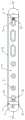
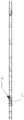
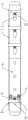
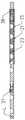
图1为本发明的第一种实施例的结构示意图;1 is a schematic structural diagram of a first embodiment of the present invention;
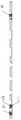
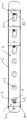
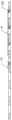
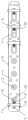
图2为本发明的第二种实施例的结构示意图;2 is a schematic structural diagram of a second embodiment of the present invention;
图3为图2中AA向的结构示意图;Fig. 3 is the structural representation of AA direction among Fig. 2;
图4为本发明的第三种实施例的结构示意图;4 is a schematic structural diagram of a third embodiment of the present invention;
图5为图4中BB向的结构示意图;Fig. 5 is the structural representation of the BB direction in Fig. 4;
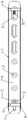
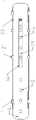
图6为本发明的第四种实施例的结构示意图;6 is a schematic structural diagram of a fourth embodiment of the present invention;
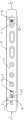
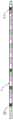
图7为本发明的第五种实施例的结构示意图;7 is a schematic structural diagram of a fifth embodiment of the present invention;
图8为本发明的第六种实施例的结构示意图;8 is a schematic structural diagram of a sixth embodiment of the present invention;
图9为图8中CC向的结构示意图;;Fig. 9 is the structural representation of CC direction among Fig. 8;;
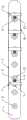
图10为本发明的第七种实施例的结构示意图;10 is a schematic structural diagram of a seventh embodiment of the present invention;
图11为本发明的第八种实施例的结构示意图;11 is a schematic structural diagram of an eighth embodiment of the present invention;
图12为本发明的第九种实施例的结构示意图;12 is a schematic structural diagram of a ninth embodiment of the present invention;
图13为本发明的第十种实施例中的一种结构示意图;13 is a schematic structural diagram of the tenth embodiment of the present invention;
图14为本发明的第十种实施例中的另一种结构示意图;14 is another schematic structural diagram of the tenth embodiment of the present invention;
图15为本发明的第十一种实施例的结构示意图;15 is a schematic structural diagram of an eleventh embodiment of the present invention;
图16为本发明的第十二种实施例的结构示意图;16 is a schematic structural diagram of a twelfth embodiment of the present invention;
图17图16中DD向的结构示意图;Figure 17 is a schematic diagram of the structure of the DD direction in Figure 16;
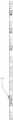
图18为本发明的第十三种实施例的结构示意图;18 is a schematic structural diagram of a thirteenth embodiment of the present invention;
图19为本发明的第十四种实施例的结构示意图;19 is a schematic structural diagram of a fourteenth embodiment of the present invention;
图20为图19另一角度的结构示意图;FIG. 20 is a schematic structural diagram of another angle of FIG. 19;
图21为本发明的第十五种实施例的结构示意图;21 is a schematic structural diagram of a fifteenth embodiment of the present invention;
图22为图21中EE向的结构示意图;Fig. 22 is the structural representation of EE direction in Fig. 21;
图23为本发明的第十六种实施例的结构示意图;23 is a schematic structural diagram of a sixteenth embodiment of the present invention;
图24为图23中FF向的结构示意图;Figure 24 is a schematic structural diagram of the FF direction in Figure 23;
图25为本发明的第十七种实施例中一种结构的示意图;25 is a schematic diagram of a structure in the seventeenth embodiment of the present invention;
图26为图25中GG向的结构示意图;Fig. 26 is the structural representation of GG direction among Fig. 25;
图27为本发明的第十七种实施例中另外一种结构的示意图;27 is a schematic diagram of another structure in the seventeenth embodiment of the present invention;
图28为图27中HH向的结构示意图;Figure 28 is a schematic structural diagram of the HH direction in Figure 27;
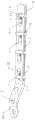
图29为本发明的第十八种实施例的结构示意图;29 is a schematic structural diagram of an eighteenth embodiment of the present invention;
图30为图29另一角度的结构示意图;FIG. 30 is a schematic structural diagram of another angle of FIG. 29;
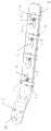
图31为本发明的第十九种实施例的结构示意图;31 is a schematic structural diagram of a nineteenth embodiment of the present invention;
图32为图31中JJ向的结构示意图;Fig. 32 is the structural representation of the JJ direction in Fig. 31;
图33为本发明的第二十种实施例的结构示意图;33 is a schematic structural diagram of the twentieth embodiment of the present invention;
图34为图33中KK向的结构示意图;Fig. 34 is the structural representation of the KK direction in Fig. 33;
图35为本发明的第二十一种实施例的结构示意图;35 is a schematic structural diagram of the twenty-first embodiment of the present invention;
图36为本发明的第二十二种实施例的结构示意图;36 is a schematic structural diagram of the twenty-second embodiment of the present invention;
图37为钢板本体上设置克氏针孔的结构示意图;Figure 37 is a schematic structural diagram of setting Kirschner pinholes on the steel plate body;
图38为牵引杆上的固定件为螺母及调压套上对应牵引孔的结构示意图;Figure 38 is a schematic structural diagram of a nut and a corresponding pulling hole on the pressure regulating sleeve as the fixing member on the pulling rod;
图39为牵引杆上的固定件为膨大部及调压套上对应牵引孔的结构示意图;Figure 39 is a schematic structural diagram of the expansion part and the corresponding towing hole on the pressure regulating sleeve;
图40为牵引杆上的固定件为套管的结构示意图;Figure 40 is a schematic structural diagram in which the fixing member on the drawbar is a sleeve;
图41为肱骨近端调压钢板的结构示意图;Figure 41 is a schematic structural diagram of the proximal humerus pressure regulating plate;
图42为腓骨远端外侧弹性钢板的结构示意图;Figure 42 is a schematic structural diagram of the outer elastic plate of the distal fibula;
图43为肱骨远端内侧调压钢板的结构示意图;Figure 43 is a schematic structural diagram of the medial pressure regulating plate of the distal humerus;
图44为股骨远端外侧调压钢板的结构示意图;Figure 44 is a schematic structural diagram of the lateral pressure regulating plate of the distal end of the femur;
图45为胫骨远端内侧调压钢板的结构示意图;Figure 45 is a schematic structural diagram of the medial pressure regulating plate of the distal tibia;
图46为肱骨远端外侧调压钢板的结构示意图;Figure 46 is a schematic structural diagram of the outer side pressure regulating plate of the distal end of the humerus;
图47为股骨近端外侧弹性钢板的结构示意图;Figure 47 is a schematic structural diagram of the outer elastic plate at the proximal end of the femur;
图48为胫骨远端前外侧调压钢板的结构示意图;Figure 48 is a schematic structural diagram of the anterolateral pressure regulating plate of the distal end of the tibia;
图49为桡骨远端掌侧调压钢板的结构示意图;Figure 49 is a schematic structural diagram of the volar pressure regulating plate at the distal end of the radius;
图50为胫骨近端外侧调压钢板的结构示意图;Figure 50 is a schematic structural diagram of the outer side pressure regulating plate of the proximal tibia;
图51为指骨T型板调压钢板的结构示意图;Figure 51 is a schematic structural diagram of the T-plate pressure regulating steel plate for the phalanx;
图52为桡骨远端背侧调压钢板的结构示意图;Figure 52 is a schematic structural diagram of the dorsal pressure regulating plate of the distal radius;
图中,1-调压套一,2-固定钉孔,3-牵引杆,4-钢板本体,5-调压钉孔,6-调压套二,7-调压孔一,8-螺母一,9-弹簧一,10-调压螺钉孔,11-调压螺钉,12-牵引槽,13-调压螺栓,14-螺母二,15-异形垫片,16-顶丝,17-侧调压孔,18-滑动挡板,19-通孔,20-偏心轴,21-防脱套,22-导槽,23-滑动板,24-上槽孔,25-下槽孔,26-防脱螺钉,27-导柱一,28-导柱二,29-膨大部,30-克氏针孔,32-弹簧二,33-固定夹,34-滑动孔,35-调压孔二,36-牵引孔,37-调压柱一,38-调压柱二。In the figure, 1-pressure regulating sleeve 1, 2-fixing nail hole, 3-drawing rod, 4-steel plate body, 5-pressure regulating nail hole, 6-
具体实施方式Detailed ways
本发明中的弹性体一、弹性体二为弹簧、弹性胶囊的一种,当为弹簧时,弹簧的两端均设置有弹簧底座,在以下的实施例中,弹性体一、弹性体二分别为弹簧一9、弹簧二32。The first elastic body and the second elastic body in the present invention are a kind of spring and elastic capsule. When they are springs, both ends of the spring are provided with spring bases. In the following embodiments, the first elastic body and the second elastic body are respectively For spring one 9, spring two 32.
下面将结合本发明实施例中的附图,对本发明实施例中的技术方案进行清楚、完整地描述,显然,所描述的实施例仅仅是本发明一部分实施例,而不是全部的实施例。基于本发明中的实施例,本领域普通技术人员在没有做出创造性劳动前提下所获得的所有其他实施例,都属于本发明保护的范围。The technical solutions in the embodiments of the present invention will be clearly and completely described below with reference to the accompanying drawings in the embodiments of the present invention. Obviously, the described embodiments are only a part of the embodiments of the present invention, but not all of the embodiments. Based on the embodiments of the present invention, all other embodiments obtained by those of ordinary skill in the art without creative efforts shall fall within the protection scope of the present invention.
本发明的第一种实施例,一种分体式弹性调压钢板,包括钢板本体4、调压装置一、调压装置二,所述钢板本体4的一侧设置有调压装置一,另一侧置有调压装置二,调压装置一通过牵引杆3连接调压装置二,所述调压装置一或调压装置二至少一个为弹性调压装置;所述钢板本体4上设置有调压钉孔5、固定钉孔2,所述固定钉孔2和调压钉孔5内均安装有骨螺钉。所述调压装置一通过牵引杆3调节调压装置二,进而调节调节调压钉孔5内骨螺钉的径向应力。The first embodiment of the present invention, a split type elastic pressure regulating steel plate, includes a
如图1所示,所述调压装置一为非弹性调压装置,所述调压装置二为弹性调压装置;所述调压装置一包括钢板本体4上设置的调压螺钉孔10、调压螺钉孔10内的调压螺钉11、调压套一1,调压螺钉孔10也可以设置成长椭圆孔,长椭圆孔内安装调压柱一37,调压柱一37的一侧为骨螺钉,另一侧安装调压螺钉11。所述调压套一1的下方设置有调压柱一37,所述调压柱一37位于调压螺钉孔10内,所述调压套一1通过牵引杆3连接调压装置二,弹性调压装置的调压形式为:所述调压螺钉11的尾部上套装有异形垫片15,所述异形垫片15的一端抵接于调压柱一37,通过更换不同异形垫片15的长度调节调压装置二沿钢板本体4的轴向应力,进而调节骨折端的轴向应力。As shown in FIG. 1 , the first pressure regulating device is an inelastic pressure regulating device, and the second pressure regulating device is an elastic pressure regulating device; The
所述调压装置二包括与牵引杆3连接的调压套二6,所述调压套二6的下方设置有调压柱二38,所述调压柱二38位于调压钉孔5内,所述调压钉孔5内安装有弹簧二32,所述弹簧二32的一端抵接于调压钉孔5内的骨螺钉,另一端抵接于调压柱二38。The second pressure regulating device includes a second
本发明的第二种实施例,如图2、图3所示,与第一种实施例的区别在于,所述调压装置一包括钢板本体4上设置的调压螺钉孔10、调压螺钉孔10内的调压螺栓13、与调压螺钉孔10连通的调压孔一7、调压套一1,所述调压套一1的下方设置有调压柱一37,所述调压柱一37位于调压孔一7内,所述调压套一1通过牵引杆3连接调压装置二。在本实施例中,弹性调压装置的调压形式为,所述调压钉孔5为至少两个相连通的螺钉孔形成的调压长孔,调压长孔内安装有调压螺栓13,调压螺栓13上安装有螺母二14,根据调压螺栓13在调压螺钉孔10内不同位置调节调压装置二沿钢板本体4的轴向应力,进而调节骨折端的轴向应力。The second embodiment of the present invention, as shown in FIGS. 2 and 3 , differs from the first embodiment in that the pressure regulating device 1 includes a pressure regulating
本发明的第三种实施例,如图4、图5所示,与第一种实施例的区别在于,在本实施例中,所述调压螺钉11更换为为偏心轴20,根据偏心轴20与调压柱一37的接触位置调节调压装置二沿钢板本体4的轴向应力,进而调节骨折端的轴向应力。The third embodiment of the present invention, as shown in FIGS. 4 and 5 , differs from the first embodiment in that, in this embodiment, the
本发明的第四种实施例,如图6所示,与第一种实施例的区别在于,在本实施例中,根据不同骨折类型,通过更换不同尾部直径的调压螺钉11调节调压装置二沿钢板本体4的轴向应力,进而调节骨折端的轴向应力。The fourth embodiment of the present invention, as shown in FIG. 6 , differs from the first embodiment in that, in this embodiment, according to different fracture types, the pressure regulating device is adjusted by replacing
本发明的第五种实施例,如图7所示,与第一种实施例的区别在于,在本实施例中,所述调压孔一7内设导柱一27,根据更换不同长度的导柱一27调节调压装置二沿钢板本体4的轴向应力,进而调节骨折端的轴向应力。The fifth embodiment of the present invention, as shown in FIG. 7 , differs from the first embodiment in that, in this embodiment, a guide post 1 27 is provided in the pressure regulating hole 1 7 , and a guide post 1 27 is arranged in the pressure regulating hole 1 7 . The
本发明的第六种实施例,如图8、9所示,与第一种实施例的区别在于,在本实施例中,所述调压孔一7沿钢板本体轴向设置,所述顶丝16与钢板本体4螺纹连接,顶丝16尾部抵接于调压柱一27,调压孔一7段处钢板厚度增厚,所述调压孔一7可凸出钢板本体4的上表面,通过调节16顶丝旋入的深度调节调压装置二沿钢板本体4的轴向应力,进而调节骨折端的轴向应力,也可在顶丝16尾部与调压柱一37之间按导柱一27。The sixth embodiment of the present invention, as shown in FIGS. 8 and 9 , differs from the first embodiment in that, in this embodiment, the pressure regulating hole 1 7 is arranged along the axial direction of the steel plate body, and the top The
本发明的第七种实施例,如图10所示,与第一种实施例的区别在于,所述调压装置一为弹性调压装置,所述调压装置一包括钢板本体4上设置的调压螺钉孔10、调压螺钉孔10内的调压螺钉11、与调压螺钉孔10连通的调压孔一7、调压套一1,所述调压套一1的下方设置有调压柱一37,所述调压柱一37位于调压孔一7内,所述调压套一1通过牵引杆3连接调压装置二,在本实施例中,弹性调压装置的调压形式为,所述调压孔一7内安装有弹簧一9,所述弹簧一9的一端抵接于调压柱一37,另一端抵接于调压螺钉孔10内的调压螺钉11,通过更换不同长度的弹簧一9调节调压螺钉11的径向应力,通过牵引杆3改变调压装置二的轴向应力,进而调节骨折端的轴向应力。The seventh embodiment of the present invention, as shown in FIG. 10 , differs from the first embodiment in that the first pressure regulating device is an elastic pressure regulating device, and the first pressure regulating device includes a pressure regulating device provided on the
调压装置二为非弹性调压装置,包括与牵引杆3连接的调压套二6、与调压钉孔5连通的调压孔二35,所述调压套二6的下方设置有调压柱二38,所述调压柱二38位于调压钉孔5内,所述调压孔二35内安装有导柱二28,所述导柱二28的一端抵接于调压钉孔5内的骨螺钉,另一端抵接于调压柱二38,也可不设置导柱二28。The second pressure regulating device is an inelastic pressure regulating device, including a second
本发明的第八种实施例,如图11所示,与第七种实施例的区别在于,调压装置二为弹性调压装置,所述调压孔二35内安装有弹簧二32,所述弹簧二32的一端抵接于调压钉孔5内的骨螺钉,另一端抵接于调压柱二38。The eighth embodiment of the present invention, as shown in FIG. 11, differs from the seventh embodiment in that the second pressure regulating device is an elastic pressure regulating device, and the second
本发明的第九种实施例,与第八种实施例的区别在于,牵引杆3上可设置一个以上的调压套二6,每个调压套二6的下方均设置有调压柱二38,调压柱二38分别位于不同的调压孔二35内,每一个调压孔二35内均安装有弹簧二32,所述弹簧二32的一端抵接于调压钉孔5内的骨螺钉,另一端抵接于调压柱二38。如图12所示,牵引杆3上设置三个调压套二6。The difference between the ninth embodiment of the present invention and the eighth embodiment is that more than one
本发明的第十种实施例,与第九种实施例的区别在于,当钢板本体4上设置多个调压螺钉孔10时,与调压螺钉孔10连通的调压孔一7可以设置在不同的调压螺钉孔10处,如图13所示,可以与第三个调压螺钉孔10连通,如图14所示,也可以与第四个调压螺钉孔10连通。The tenth embodiment of the present invention is different from the ninth embodiment in that when a plurality of pressure regulating screw holes 10 are arranged on the
本发明的第十一种实施例,与第九种实施例的区别在于,如图15所示,所述调压孔一7内安装有弹簧一9,弹簧一9的两端均固定安装有弹性底座,弹性底座上分别设置通孔19,所述通孔19沿弹簧一9径向设置,所述调压孔一7端设置为盲孔,所述弹性体的一端安装在盲孔内,另一端抵接于调压螺钉孔10内的调压柱一37,通过更换不同长度的弹簧一9,调节调压装置二沿钢板本体4的轴向应力,进而调节骨折端的轴向应力。The eleventh embodiment of the present invention is different from the ninth embodiment in that, as shown in FIG. 15 , a spring one 9 is installed in the pressure regulating hole one 7, and both ends of the spring one 9 are fixedly installed with a spring one 9. Elastic base, through
本发明的第十二种实施例,如图16、17所示,与第九种实施例的区别在于,所述调压孔一7内安装有顶丝16、弹簧一9,所述顶丝16与钢板本体4螺纹连接,顶丝16顶端抵接于弹簧一9,调压孔一7段处钢板厚度增厚,所述调压孔一7可凸出钢板本体4的上表面,弹簧一9的一端抵接于顶丝16,另一端抵接于调压柱一37,通过调节顶丝16旋入的深度调节调压螺钉孔5内骨螺钉的径向应力,进而调节骨折端的轴向应力。The twelfth embodiment of the present invention, as shown in FIGS. 16 and 17 , differs from the ninth embodiment in that a
本发明的第十三种实施例,如图18所示,与第九种实施例的区别在于,调压钉孔5的一侧设置有与之连通的调压孔二35,所述调压孔二35内安装有弹簧二32,所述弹簧二32的一端抵接于调压钉孔5内的骨螺钉,另一端抵接于调压柱二38。As shown in FIG. 18 , the thirteenth embodiment of the present invention is different from the ninth embodiment in that one side of the pressure regulating
所述钢板本体4的两侧分别设置有牵引槽12,所述调压套一1、调压套二6上分别设置牵引孔36,所述牵引杆3穿设于牵引孔36并与其紧固连接,本实施例中通过螺母一8固定连接;所述牵引杆3为金属杆或者线缆中的一种。The two sides of the
本发明的第十四种实施例,如图19、20所示,与第九种实施例的区别在于,所述钢板本体4上设置有两个侧调压孔17,调压孔一7中安装有弹簧一9,侧调压孔17为设于钢板本体4两侧的长孔,且沿钢板本体4轴向设置,所述长孔为至少两个相连通的螺钉孔,所述钢板本体4上设有滑动挡板18,滑动挡板18上两端设有螺钉孔、中间设滑动柱,滑动柱抵接于弹簧一9,可在调压孔一7内滑动,调压螺栓13和螺母二14通过螺钉孔将滑动挡板18固定于钢板本体4上,根据调压螺栓13在侧调压孔17内不同位置调节调压螺钉11的径向应力,进而调节骨折端的轴向应力。The fourteenth embodiment of the present invention, as shown in FIGS. 19 and 20 , differs from the ninth embodiment in that the
本发明的第十五种实施例,如图21、22所示,与第一种实施例的区别在于,所述调压套一1上的调压柱一37安装在第三个固定钉孔2的右侧,调压套二6为半套形式,其两端扣合在钢板本体4两侧,调压套二6的上表面上设置有长槽孔形成的上槽孔24,上槽孔24与调压钉孔5对应,且上槽孔24孔径向尺寸大于调压钉孔5的尺寸。The fifteenth embodiment of the present invention, as shown in Figures 21 and 22, differs from the first embodiment in that the pressure regulating column 1 37 on the pressure regulating sleeve 1 is installed in the third fixing nail hole On the right side of 2, the second
本发明的第十六种实施例,如图23、24所示,与第十五种实施例的区别在于,调压套二6为全套形式,当调压套为全套形式时,调压套的上表面和下表面上分别设置有长槽孔形成的上槽孔24和下槽孔25;所述上槽孔24和下槽孔25均与调压钉孔5对应,且上槽孔24和下槽孔25径向尺寸大于调压钉孔5的尺寸。The sixteenth embodiment of the present invention, as shown in Figures 23 and 24, differs from the fifteenth embodiment in that the
本发明的第十七种实施例,与第一种实施例的区别在于,所述调压套一1和调压套二6为一体结构构成的调压套,根据其与钢板本体4的连接形式设置为半套或全套形式,当为半套时,如图25、26所示,其两端扣合在钢板本体4两侧,调压套的上表面上设置有长槽孔形成的上槽孔24;如图27、28所示,当调压套为全套形式时,调压套的上表面和下表面上分别设置有长槽孔形成的上槽孔24和下槽孔25;所述上槽孔24和下槽孔25与调压钉孔5对应,且径向尺寸大于调压钉孔5的尺寸。The seventeenth embodiment of the present invention is different from the first embodiment in that the pressure regulating sleeve formed by the pressure regulating sleeve 1 and the
本发明的第十八种实施例,如图29、30所示,与第十种实施例的区别在于,所述钢板本体4上设置有滑动孔34,所述滑动孔34与调压孔二35连通,滑动孔34内安装有滑动板23,滑动板23上设置有调压钉孔5,调压孔二35内安装有弹簧二32,所述弹簧二32的一端抵接于滑动板23,另一端抵接于调压柱二38,通过调节滑动板23的轴向应力改变骨螺钉的径向应力,进而调节骨折端的轴向应力。The eighteenth embodiment of the present invention, as shown in FIGS. 29 and 30 , differs from the tenth embodiment in that the
作为本实施例的进一步优化,所述滑动孔34为异型滑动孔34,钢板本体4上表面的开口大于下表面的开口,滑动孔34轴向长度大于滑动板23轴向长度。滑动板23上设置有防脱板21,根据其表面覆盖钢板本体4大小设为带状。当调压套一1、调压套二6、防脱板21为带状或者半套形式时,钢板本体4的下表面的两侧可对称设置导槽22,导槽22的设置便于当调压套一1、调压套二6、防脱板21沿钢板本体4轴向滑动,本实施例中,防脱板21为带状。As a further optimization of this embodiment, the sliding
本发明的第十九种实施例,如图31、32所示,与第十八种实施例的区别在于,防脱板21设置为半套形式,其两端扣合在钢板本体4两侧,上表面上设置有长槽孔形成的上槽孔24,上槽孔24与调压钉孔5对应,且上槽孔24径向尺寸大于调压钉孔5的尺寸。The nineteenth embodiment of the present invention, as shown in FIGS. 31 and 32 , differs from the eighteenth embodiment in that the
本发明的第二十种实施例,如图33、34所示,与第十九种实施例的区别在于,防脱板21为设置为全套形式,其上表面和下表面上分别设置有长槽孔形成的上槽孔24和下槽孔25,所述上槽孔24和下槽孔25均与调压钉孔5对应。The twentieth embodiment of the present invention, as shown in Figures 33 and 34, differs from the nineteenth embodiment in that the
本发明的第二十一种实施例,如图35所示,与第十八种实施例的区别在于,将带状的防脱板21更换为至少两个防脱螺钉26,所述防脱螺钉26与钢板本体4螺纹连接,防脱螺钉26尾部位压合在滑动板23上表面,阻止滑动板23脱出钢板本体4。The twenty-first embodiment of the present invention, as shown in FIG. 35, differs from the eighteenth embodiment in that the strip-shaped
本发明的第二十二种实施例,如图36所示,所述钢板本体4设为与骨骼形态一致且具有一定弧度的弧形钢板,钢板本体4上表面、下表面径向设为具有一定弧度的弧面;如图37所示,所述钢板本体4设至少一个克氏针孔30,用于临时固定骨骼;所述钢板本体4、防脱板21两侧的下表面可设凹槽。如图41-图52所示,钢板本体4一端可以设为与人体骨骼的解剖形态相一致,且具有一定弧度的解剖钢板。如:肱骨近端调压钢板、腓骨远端外侧弹性钢板、肱骨远端内侧调压钢板、股骨远端外侧调压钢板、胫骨远端内侧调压钢板、肱骨远端外侧调压钢板、股骨近端外侧弹性钢板、胫骨远端前外侧调压钢板、桡骨远端掌侧调压钢板、胫骨近端外侧调压钢板、指骨T型板调压钢板、桡骨远端背侧调压钢板等。In the twenty-second embodiment of the present invention, as shown in FIG. 36 , the
作为本发明的进一步变形,所述钢板本体4上设置的调压钉孔5、调压孔一7、固定钉孔2有如下形式之一:As a further variant of the present invention, the pressure regulating
①所述钢板本体4一端设置至少两个调压钉孔5和至少一个调压孔一7。① One end of the
②所述钢板本体4上两端都设置为调压钉孔5和调压孔一7,所述调压钉孔5、调压孔一7对称设置在钢板本体4上。② Both ends of the
③所述钢板本体4一端设置为固定钉孔2端,另一端设置为调压钉孔5端,固定钉孔2一端设为与人体四肢骨骼关节部位解剖形态一致的解剖板,调压钉孔5端设置至少两个调压钉孔5和至少一个调压孔一7。3. One end of the
作为本发明的进一步优化,如图38、39、40所示,所述调压装置一通过牵引杆3与调压装置二连接,调压套一1上设置有牵引孔36,所述牵引杆3上设置有螺纹段,所述牵引杆3的一端穿出牵引孔36,所述牵引杆3的另一端通过固定件固定安装在调压套二6上,所述固定件为螺母一8、膨大部29或者固定夹33中的一种,此时的牵引孔36为开放式;当为螺母一8时,牵引杆3上设置有螺纹段,螺纹段上安装有螺母一8,螺母一8与牵引杆3螺纹连接。此时的牵引孔36为开放式或闭合。As a further optimization of the present invention, as shown in FIGS. 38 , 39 and 40 , the first pressure regulating device is connected to the second pressure regulating device through a
以上所述仅为本发明的较佳实施例而已,并不用以限制本发明的实施例,如在图29、31、33、35中,将调压装置一的形式更换为图1、2、4、6、7、8中的形式之一,在钢板本体一侧设置调压套一时,将调压套一的形式或者移动方式进行变化等,凡在本发明的精神和原则之内,所作的任何修改、等同替换、改进等,均应包含在本发明的保护范围之内。The above descriptions are only preferred embodiments of the present invention, and are not intended to limit the embodiments of the present invention. One of the forms in 4, 6, 7, and 8, when a pressure regulating sleeve is set on one side of the steel plate body, the form or moving method of the pressure regulating sleeve 1 is changed, etc., all within the spirit and principle of the present invention, the Any modification, equivalent replacement, improvement, etc., should be included within the protection scope of the present invention.
Claims (14)
Priority Applications (1)
| Application Number | Priority Date | Filing Date | Title |
|---|---|---|---|
| CN202011028012.7ACN112120775B (en) | 2020-09-26 | 2020-09-26 | A split elastic pressure regulating steel plate |
Applications Claiming Priority (1)
| Application Number | Priority Date | Filing Date | Title |
|---|---|---|---|
| CN202011028012.7ACN112120775B (en) | 2020-09-26 | 2020-09-26 | A split elastic pressure regulating steel plate |
Publications (2)
| Publication Number | Publication Date |
|---|---|
| CN112120775Atrue CN112120775A (en) | 2020-12-25 |
| CN112120775B CN112120775B (en) | 2025-07-15 |
Family
ID=73840456
Family Applications (1)
| Application Number | Title | Priority Date | Filing Date |
|---|---|---|---|
| CN202011028012.7AActiveCN112120775B (en) | 2020-09-26 | 2020-09-26 | A split elastic pressure regulating steel plate |
Country Status (1)
| Country | Link |
|---|---|
| CN (1) | CN112120775B (en) |
Cited By (2)
| Publication number | Priority date | Publication date | Assignee | Title |
|---|---|---|---|---|
| CN112656501A (en)* | 2020-09-26 | 2021-04-16 | 宋若怡 | Integral type elasticity pressure regulating steel sheet |
| CN112971957A (en)* | 2021-04-01 | 2021-06-18 | 河南科科生物科技有限公司 | Sliding sleeve type elastic pressure regulating steel plate |
Citations (13)
| Publication number | Priority date | Publication date | Assignee | Title |
|---|---|---|---|---|
| CN101836888A (en)* | 2009-03-16 | 2010-09-22 | 周小军 | Multifunctional steel plate system for external fixation |
| CN101983617A (en)* | 2010-12-05 | 2011-03-09 | 明彩 | Trace slide type unstressed shielding steel plate |
| US20130204304A1 (en)* | 2012-02-03 | 2013-08-08 | Genesis Facture Care Inc. | Bone plate for elastic osteosynthesis |
| US20130304067A1 (en)* | 2012-05-10 | 2013-11-14 | Spinal Simplicity Llc | Dynamic bone fracture plates |
| CN104546101A (en)* | 2013-10-24 | 2015-04-29 | 纪玉清 | Dynamic fixing steel plate for fracture |
| WO2016032273A1 (en)* | 2014-08-28 | 2016-03-03 | 주식회사 케이씨스 | Bone plate for fracture |
| CN105520775A (en)* | 2015-04-20 | 2016-04-27 | 纪玉清 | Fracture fixation device capable of realizing longitudinal dynamic sliding |
| CN107260292A (en)* | 2017-08-10 | 2017-10-20 | 河海大学常州校区 | A kind of plate fixation system being consistent with knitting process |
| US20180049785A1 (en)* | 2016-08-17 | 2018-02-22 | Globus Medical, Inc. | Stabilization systems |
| CN209826931U (en)* | 2019-03-25 | 2019-12-24 | 张一鸣 | Double-rail type sliding bone-knitting device for femoral shaft fracture |
| US20200187998A1 (en)* | 2016-08-17 | 2020-06-18 | Globus Medical, Inc. | Distal radius stabilization system |
| CN211325517U (en)* | 2019-10-21 | 2020-08-25 | 天津市威曼生物材料有限公司 | Fracture adjusting and resetting device |
| CN215994203U (en)* | 2020-09-26 | 2022-03-11 | 宋若怡 | Split type elasticity pressure regulating steel sheet |
- 2020
- 2020-09-26CNCN202011028012.7Apatent/CN112120775B/enactiveActive
Patent Citations (13)
| Publication number | Priority date | Publication date | Assignee | Title |
|---|---|---|---|---|
| CN101836888A (en)* | 2009-03-16 | 2010-09-22 | 周小军 | Multifunctional steel plate system for external fixation |
| CN101983617A (en)* | 2010-12-05 | 2011-03-09 | 明彩 | Trace slide type unstressed shielding steel plate |
| US20130204304A1 (en)* | 2012-02-03 | 2013-08-08 | Genesis Facture Care Inc. | Bone plate for elastic osteosynthesis |
| US20130304067A1 (en)* | 2012-05-10 | 2013-11-14 | Spinal Simplicity Llc | Dynamic bone fracture plates |
| CN104546101A (en)* | 2013-10-24 | 2015-04-29 | 纪玉清 | Dynamic fixing steel plate for fracture |
| WO2016032273A1 (en)* | 2014-08-28 | 2016-03-03 | 주식회사 케이씨스 | Bone plate for fracture |
| CN105520775A (en)* | 2015-04-20 | 2016-04-27 | 纪玉清 | Fracture fixation device capable of realizing longitudinal dynamic sliding |
| US20180049785A1 (en)* | 2016-08-17 | 2018-02-22 | Globus Medical, Inc. | Stabilization systems |
| US20200187998A1 (en)* | 2016-08-17 | 2020-06-18 | Globus Medical, Inc. | Distal radius stabilization system |
| CN107260292A (en)* | 2017-08-10 | 2017-10-20 | 河海大学常州校区 | A kind of plate fixation system being consistent with knitting process |
| CN209826931U (en)* | 2019-03-25 | 2019-12-24 | 张一鸣 | Double-rail type sliding bone-knitting device for femoral shaft fracture |
| CN211325517U (en)* | 2019-10-21 | 2020-08-25 | 天津市威曼生物材料有限公司 | Fracture adjusting and resetting device |
| CN215994203U (en)* | 2020-09-26 | 2022-03-11 | 宋若怡 | Split type elasticity pressure regulating steel sheet |
Cited By (3)
| Publication number | Priority date | Publication date | Assignee | Title |
|---|---|---|---|---|
| CN112656501A (en)* | 2020-09-26 | 2021-04-16 | 宋若怡 | Integral type elasticity pressure regulating steel sheet |
| CN112656501B (en)* | 2020-09-26 | 2025-09-09 | 河南科科生物科技有限公司 | Integral elastic voltage regulating steel plate |
| CN112971957A (en)* | 2021-04-01 | 2021-06-18 | 河南科科生物科技有限公司 | Sliding sleeve type elastic pressure regulating steel plate |
Also Published As
| Publication number | Publication date |
|---|---|
| CN112120775B (en) | 2025-07-15 |
Similar Documents
| Publication | Publication Date | Title |
|---|---|---|
| CN112120775A (en) | A split type elastic pressure regulating steel plate | |
| EP1272116B1 (en) | Osteosynthetic anchoring element | |
| CN112494128B (en) | A top pressure regulating steel plate | |
| CN215994204U (en) | Top pressure regulating steel plate | |
| CN105342676B (en) | Multifunctional assembled physiological bone pressurization external fixed support for bone | |
| CN215994203U (en) | Split type elasticity pressure regulating steel sheet | |
| CN215994202U (en) | A split pressure regulating steel plate | |
| CN102319103B (en) | Pressurized locking combined screw system and special composite screwdriver | |
| CN112220547B (en) | A split pressure regulating steel plate | |
| CN117100376A (en) | A minimally invasive fracture reduction and fixation system | |
| CN101416900B (en) | External fixation rack elasticity device | |
| CN203953727U (en) | A kind of fixing holdfast of soft tissue repair of suitable implantation spongy bone | |
| CN114681030B (en) | A fixation device for posterior cruciate ligament tibial attachment avulsion fracture and use method thereof | |
| CN107080581A (en) | Elastic internal fixation system and pressure-adjustable hold-down bars | |
| CN103099668B (en) | Expanding type extrusion nail | |
| CN103800065A (en) | Malleolus medialis fixing steel plate system | |
| CN204468250U (en) | A kind of hollow pressurization nail | |
| CN200998302Y (en) | Limited dynamic pressurization hip screw device | |
| CN205163219U (en) | Modular multi -functional physiology bone pressurization bone external fixation support | |
| CN102525629B (en) | Elastic interlocking intramedullary nail fixed in fractured bone | |
| CN215349375U (en) | An integrated elastic pressure regulating steel plate | |
| CN112494129B (en) | Integral type pressure regulating steel sheet | |
| CN207979765U (en) | It is fixed in the bone that can be extended automatically | |
| CN202776475U (en) | Centralizing bone holding forceps | |
| CN206080668U (en) | But fixing system and pressure regulating hold -down bars in elasticity |
Legal Events
| Date | Code | Title | Description |
|---|---|---|---|
| PB01 | Publication | ||
| PB01 | Publication | ||
| SE01 | Entry into force of request for substantive examination | ||
| SE01 | Entry into force of request for substantive examination | ||
| TA01 | Transfer of patent application right | Effective date of registration:20240914 Address after:No. 430, donglingyuan Road, Zhaocheng District, Henan Province Applicant after:HENAN KEKE BIOTECHNOLOGY Co.,Ltd. Country or region after:China Address before:1904, 19th floor, building 20, Hualin City home, courtyard 7, Cuihua Road, Jinshui District, Zhengzhou City, Henan Province Applicant before:Song Ruoyi Country or region before:China | |
| TA01 | Transfer of patent application right | ||
| GR01 | Patent grant | ||
| GR01 | Patent grant |