CN112107353A - Gynecological clinical curettage device - Google Patents
Gynecological clinical curettage deviceDownload PDFInfo
- Publication number
- CN112107353A CN112107353ACN202011079402.7ACN202011079402ACN112107353ACN 112107353 ACN112107353 ACN 112107353ACN 202011079402 ACN202011079402 ACN 202011079402ACN 112107353 ACN112107353 ACN 112107353A
- Authority
- CN
- China
- Prior art keywords
- curettage
- handle
- plate
- front side
- rear side
- Prior art date
- Legal status (The legal status is an assumption and is not a legal conclusion. Google has not performed a legal analysis and makes no representation as to the accuracy of the status listed.)
- Granted
Links
Images


Classifications
- A—HUMAN NECESSITIES
- A61—MEDICAL OR VETERINARY SCIENCE; HYGIENE
- A61B—DIAGNOSIS; SURGERY; IDENTIFICATION
- A61B17/00—Surgical instruments, devices or methods
- A61B17/42—Gynaecological or obstetrical instruments or methods
- A61B17/4241—Instruments for manoeuvring or retracting the uterus, e.g. during laparoscopic surgery
- A—HUMAN NECESSITIES
- A61—MEDICAL OR VETERINARY SCIENCE; HYGIENE
- A61B—DIAGNOSIS; SURGERY; IDENTIFICATION
- A61B17/00—Surgical instruments, devices or methods
- A61B17/42—Gynaecological or obstetrical instruments or methods
- A61B2017/4216—Operations on uterus, e.g. endometrium
Landscapes
- Health & Medical Sciences (AREA)
- Surgery (AREA)
- Life Sciences & Earth Sciences (AREA)
- Biomedical Technology (AREA)
- Medical Informatics (AREA)
- Reproductive Health (AREA)
- Pregnancy & Childbirth (AREA)
- Engineering & Computer Science (AREA)
- Gynecology & Obstetrics (AREA)
- Heart & Thoracic Surgery (AREA)
- Nuclear Medicine, Radiotherapy & Molecular Imaging (AREA)
- Molecular Biology (AREA)
- Animal Behavior & Ethology (AREA)
- General Health & Medical Sciences (AREA)
- Public Health (AREA)
- Veterinary Medicine (AREA)
- Surgical Instruments (AREA)
Abstract
Description
Translated fromChinese技术领域technical field
本发明涉及妇科临床的技术领域,特别是涉及一种妇科临床刮宫器。The invention relates to the technical field of gynecological clinic, in particular to a gynecological clinical curettage.
背景技术Background technique
众所周知,妇科临床刮宫器是一种在妇科临床诊断和治疗过程中,用于刮取子宫内膜或宫腔内容物手术的配套器具,其在的妇科临床诊断和治疗的领域中得到了广泛的使用。As we all know, the gynecological clinical curettage is a supporting device used for scraping endometrial or uterine cavity contents in the process of gynecological clinical diagnosis and treatment. It has been widely used in the field of gynecological clinical diagnosis and treatment. use.
中国专利号为CN208677458U的实用新型专利公开了一种妇科临床刮宫器,其大致描述为:包括下刮杆,下刮杆包括呈长方形杆状的杆体一和呈勺状的刮部,刮部的外壁连于杆体一的右端端部;上刮杆,上刮杆包括呈长方形杆状的杆体二和盖设部,盖设部连于杆体二的右端端部,盖设部能够盖设在刮部的开口处;其中,上刮杆位于下刮杆上方,上刮杆与下刮杆相连且之间具有滑动连接结构。现有的妇科临床刮宫器使用时,通过滑动连接结构,盖设部能够向靠近或远离刮部的方向运动,从而完成对子宫的刮取操作。The utility model patent with the Chinese patent number CN208677458U discloses a gynecological clinical curettage, which is roughly described as: comprising a lower scraper rod, the lower scraper rod includes a rectangular rod-shaped rod body and a spoon-shaped scraper, the scraper The outer wall is connected to the right end of the
现有的妇科临床刮宫器使用时发现,其刮取操作需要一定的经验和操作技巧,需要长期的练习才能熟练掌握,从而容易在刮取过程中,因操作不当对病患造成一定的伤害,影响手术的效果。When the existing gynecological clinical curettage is used, it is found that its scraping operation requires certain experience and operation skills, and requires long-term practice to master it, so that it is easy to cause certain damage to the patient due to improper operation during the scraping process. affect the outcome of surgery.
发明内容SUMMARY OF THE INVENTION
(一)解决的技术问题(1) Technical problems solved
针对现有技术的不足,本发明提供了一种妇科临床刮宫器,其具有操作简便,使用灵活等优点,降低刮取难度,避免手术中对病患造成意外损伤。Aiming at the deficiencies of the prior art, the present invention provides a gynecological clinical curettage, which has the advantages of simple operation, flexible use, etc., reduces the difficulty of scraping, and avoids accidental damage to patients during surgery.
(二)技术方案(2) Technical solutions
为实现上述目的,本发明提供如下技术方案:一种妇科临床刮宫器,包括上扩板、下扩板、握把、连接板、两个滑块、滚轴、滑动底座、四个连接杆、两个吸附铁块、转动轴、转动齿轮、两个转动把手、控制杆、两个蓄电池、按压式开关、两个电磁铁、刮宫杆和刮宫环,所述上扩板、下扩板和握把的截面均为半圆弧型,握把的顶部左侧与下扩板的右端连接,所述连接板的顶部设置有连接槽,上扩板右端的前侧和后侧分别与连接槽内部的前侧和后侧固定连接,连接板上部的前侧和后侧分别与握把内部的前侧和后侧转动连接,握把的前侧和后侧分别设置有两个调节通孔,两个滑块分别与两个调节通孔的内部滑动连接,所述滚轴的前端和后端分别与两个滑块的内侧转动连接,滚轴的左侧与连接板的右侧相接触,所述滑动底座位于下扩板的内部,四个连接杆分别固定在滑动底座前侧的左侧和右侧以及后侧的左侧和右侧,四个连接杆的外端分别与下扩板内侧的左前侧、右前侧、左后侧和右后侧滑动连接,滑动底座的顶部设置有滑动槽,两个吸附铁块分别镶嵌在滑动槽内部的前侧中部后侧中部,下扩板右侧的前侧和后侧分别设置有两个转动孔,所述转动轴的前侧和后侧分别与两个转动孔的内部转动连接,转动轴位于滑动底座的下方,转动齿轮套装在转动轴的中部,滑动底座的底部设置有滑动齿条,滑动齿条的底部与转动齿轮的顶部啮合,两个转动把手分别固定在转动轴的前端和后端,所述控制杆放置在滑动槽的内部,控制杆的右侧内部设置有电池腔,两个蓄电池均安装在电池腔的内部,两个蓄电池相互串联,所述按压式开关安装在控制杆的右端,按压式开关与两个蓄电池电连接,两个电磁铁分别安装在控制杆中部的前侧和后侧,两个电磁铁均与两个蓄电池电连接,所述刮宫杆的右端与控制杆的左端连接,所述刮宫环的右端与刮宫杆的左端可拆卸连接。In order to achieve the above purpose, the present invention provides the following technical solutions: a gynecological clinical curettage, comprising an upper expanding plate, a lower expanding plate, a grip, a connecting plate, two sliding blocks, a roller, a sliding base, four connecting rods, Two suction iron blocks, a rotating shaft, a rotating gear, two rotating handles, a control lever, two accumulators, a push switch, two electromagnets, a curettage rod and a curettage ring, the upper expanding plate, the lower expanding plate and the grip The cross-section of the handle is semi-circular arc type, the top left side of the handle is connected with the right end of the lower expansion plate, the top of the connection plate is provided with a connection groove, and the front and rear sides of the right end of the upper expansion plate are respectively connected with the inside of the connection groove. The front and rear sides of the handle are fixedly connected, and the front and rear sides of the upper part of the connecting plate are respectively connected to the front and rear sides of the handle. Each slider is slidably connected to the inside of the two adjusting through holes, the front and rear ends of the roller are respectively connected in rotation with the inner sides of the two sliders, and the left side of the roller is in contact with the right side of the connecting plate, so The sliding base is located inside the lower expansion plate, the four connecting rods are respectively fixed on the left and right sides of the front side of the sliding base and the left and right sides of the rear side, and the outer ends of the four connecting rods are respectively connected with the inner side of the lower expansion plate. The left front side, right front side, left rear side and right rear side are connected by sliding connection, the top of the sliding base is provided with a sliding groove, and the two adsorption iron blocks are respectively embedded in the middle of the front side and the middle of the rear side inside the sliding groove, and the right side of the lower expansion plate is The front side and the rear side of the rotating shaft are respectively provided with two rotating holes, the front and rear sides of the rotating shaft are respectively rotatably connected with the inner parts of the two rotating holes, the rotating shaft is located under the sliding base, and the rotating gear is sleeved on the inner part of the rotating shaft. In the middle, the bottom of the sliding base is provided with a sliding rack, the bottom of the sliding rack is engaged with the top of the rotating gear, the two rotating handles are respectively fixed on the front and rear of the rotating shaft, and the control rod is placed inside the sliding groove, A battery cavity is arranged inside the right side of the control rod, two batteries are installed inside the battery cavity, the two batteries are connected in series with each other, the push switch is installed on the right end of the control rod, and the push switch is electrically connected with the two batteries, Two electromagnets are respectively installed on the front side and the back side of the middle part of the control rod, both electromagnets are electrically connected with two accumulators, the right end of the curettage rod is connected with the left end of the control rod, and the right end of the curettage ring is connected with the curettage. The left end of the rod is detachably attached.
优选的,所述刮宫杆为圆柱形结构。Preferably, the curettage rod is a cylindrical structure.
优选的,所述刮宫环的材质为医用硬质硅胶材质。Preferably, the material of the curettage ring is medical hard silicone material.
优选的,所述滑动底座的材质为医用铝板材质。Preferably, the material of the sliding base is a medical aluminum plate material.
优选的,还包括两个保护软垫,两个保护软垫分别安装在所述上扩板的顶部外侧和下扩板的底部外侧。Preferably, two protective soft pads are also included, and the two protective soft pads are respectively installed on the outer side of the top of the upper expansion plate and the outer side of the bottom of the lower expansion plate.
优选的,还包括把套,所述把套套装在所述握把的外侧,把套的前侧和后侧分别设置有两个连接通孔,两个连接通孔分别与两个调节通孔连通,两个滑块分别伸出两个连接通孔。Preferably, it also includes a handle sleeve, the handle sleeve is sleeved on the outer side of the handle, the front side and the rear side of the handle sleeve are respectively provided with two connecting through holes, and the two connecting through holes are respectively connected with two adjusting through holes. connected, the two sliders respectively protrude from the two connecting through holes.
优选的,还包括微型摄像头,所述微型摄像头安装在速搜控制杆的左端,微型摄像头位于所述刮宫杆的上方,微型摄像头与两个蓄电池电连接。Preferably, it also includes a micro camera, the micro camera is installed on the left end of the speed search control rod, the micro camera is located above the curettage rod, and the micro camera is electrically connected to the two accumulators.
优选的,还包括两个照明灯,两个照明灯分别安装在所述微型摄像头的前侧和后侧,两个照明灯均与两个蓄电池电连接。Preferably, it also includes two lighting lamps, which are respectively installed on the front side and the rear side of the micro camera, and both are electrically connected to the two batteries.
(三)有益效果(3) Beneficial effects
与现有技术相比,本发明提供了一种妇科临床刮宫器,具备以下有益效果:Compared with the prior art, the present invention provides a gynecological clinical curettage, which has the following beneficial effects:
该妇科临床刮宫器,通过向下滑动两个滑块和滚轴,可以使滚轴推动连接板向左侧转动,从而使连接板带动上扩板的顶部向上移动,从而使上扩板和下扩板对阴部进行扩张,然后,打开按压式开关,使电磁铁吸附在吸附铁块上,从而将控制杆和刮宫环等固定在滑动底座上,然后,通过旋转转动把手使转动齿轮带动滑动齿条移动,从而使刮宫环伸入到子宫内,然后切断电磁铁的电源,使控制杆与滑动底座分离,然后向外拉动控制杆,使刮宫环完成刮宫操作;通过转动齿轮和滑动齿条的配合,可以精确的控制刮宫环的位置,从而降低刮宫环在使用的操作难度,避免手术对患者造成意外损伤;另外,对于经验较为丰富的医生,可以在操作时关闭电磁铁,直接使用控制杆对刮宫环进行控制,从而提高手术的效率。In the gynecological clinical curettage, by sliding the two sliders and the roller downward, the roller can push the connecting plate to rotate to the left, so that the connecting plate drives the top of the upper expanding plate to move upward, so that the upper expanding plate and the lower plate can be moved upward. The expansion plate expands the genitals, and then turns on the push switch, so that the electromagnet is adsorbed on the adsorption iron block, so as to fix the control rod and the curettage ring on the sliding base, and then, by rotating the rotating handle, the rotating gear drives the sliding teeth The bar moves so that the curettage ring extends into the uterus, then cuts off the power of the electromagnet, separates the control rod from the sliding base, and then pulls the control rod outward to make the curettage ring complete the curettage operation; In cooperation, the position of the curettage ring can be accurately controlled, thereby reducing the difficulty of operation of the curettage ring and avoiding accidental damage to the patient during surgery; in addition, for more experienced doctors, the electromagnet can be turned off during operation, and the control rod can be used directly. Control the curettage ring to improve the efficiency of the operation.
附图说明Description of drawings
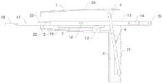
图1为本发明的结构示意图;Fig. 1 is the structural representation of the present invention;
图2为本发明的右侧结构示意图;Fig. 2 is the right side structural representation of the present invention;
图3为本发明的握把的横截面结构示意图;Fig. 3 is the cross-sectional structure schematic diagram of the handle of the present invention;
图4为本发明的控制杆的俯视结构示意图;Fig. 4 is the top-view structure schematic diagram of the control rod of the present invention;
图5为本发明的下扩板的右侧结构示意图;5 is a schematic view of the right side structure of the lower expansion plate of the present invention;
附图中标记:1、上扩板;2、下扩板;3、握把;4、连接板;5、滑块;6、滚轴;7、滑动底座;8、连接杆;9、吸附铁块;10、转动轴;11、转动齿轮;12、转动把手;13、控制杆;14、蓄电池;15、按压式开关;16、电磁铁;17、刮宫杆;18、刮宫环;19、滑动齿条;20、保护软垫;21、把套;22、微型摄像头;23、照明灯。Symbols in the drawings: 1. Upper expansion plate; 2. Lower expansion plate; 3. Grip; 4. Connecting plate; 5. Slider; 6. Roller; 7. Sliding base; 8. Connecting rod; 9. Adsorption Iron block; 10, rotating shaft; 11, rotating gear; 12, rotating handle; 13, control lever; 14, battery; 15, push switch; 16, electromagnet; 17, curettage rod; 18, curettage ring; 19, Sliding rack; 20. Protection cushion; 21. Grip; 22. Micro camera; 23. Lighting lamp.
具体实施方式Detailed ways
下面将结合本发明实施例中的附图,对本发明实施例中的技术方案进行清楚、完整地描述,显然,所描述的实施例仅仅是本发明一部分实施例,而不是全部的实施例。基于本发明中的实施例,本领域普通技术人员在没有做出创造性劳动前提下所获得的所有其他实施例,都属于本发明保护的范围。The technical solutions in the embodiments of the present invention will be clearly and completely described below with reference to the accompanying drawings in the embodiments of the present invention. Obviously, the described embodiments are only a part of the embodiments of the present invention, but not all of the embodiments. Based on the embodiments of the present invention, all other embodiments obtained by those of ordinary skill in the art without creative efforts shall fall within the protection scope of the present invention.
请参阅图1-5,本发明的一种妇科临床刮宫器,包括上扩板1、下扩板2、握把3、连接板4、两个滑块5、滚轴6、滑动底座7、四个连接杆8、两个吸附铁块9、转动轴10、转动齿轮11、两个转动把手12、控制杆13、两个蓄电池14、按压式开关15、两个电磁铁16、刮宫杆17和刮宫环18,所述上扩板1、下扩板2和握把3的截面均为半圆弧型,握把3的顶部左侧与下扩板2的右端连接,所述连接板4的顶部设置有连接槽,上扩板1右端的前侧和后侧分别与连接槽内部的前侧和后侧固定连接,连接板4上部的前侧和后侧分别与握把3内部的前侧和后侧转动连接,握把3的前侧和后侧分别设置有两个调节通孔,两个滑块5分别与两个调节通孔的内部滑动连接,所述滚轴6的前端和后端分别与两个滑块5的内侧转动连接,滚轴6的左侧与连接板4的右侧相接触,所述滑动底座7位于下扩板2的内部,四个连接杆8分别固定在滑动底座7前侧的左侧和右侧以及后侧的左侧和右侧,四个连接杆8的外端分别与下扩板2内侧的左前侧、右前侧、左后侧和右后侧滑动连接,滑动底座7的顶部设置有滑动槽,两个吸附铁块9分别镶嵌在滑动槽内部的前侧中部后侧中部,所述滑动底座7的材质为医用铝板材质,从而避免电磁铁16与滑动底座7产生吸附作用,便于控制杆13的操作;下扩板2右侧的前侧和后侧分别设置有两个转动孔,所述转动轴10的前侧和后侧分别与两个转动孔的内部转动连接,转动轴10位于滑动底座7的下方,转动齿轮11套装在转动轴10的中部,滑动底座7的底部设置有滑动齿条19,滑动齿条19的底部与转动齿轮11的顶部啮合,两个转动把手12分别固定在转动轴10的前端和后端,所述控制杆13放置在滑动槽的内部,控制杆13的右侧内部设置有电池腔,两个蓄电池14均安装在电池腔的内部,两个蓄电池14相互串联,所述按压式开关15安装在控制杆13的右端,按压式开关15与两个蓄电池14电连接,两个电磁铁16分别安装在控制杆13中部的前侧和后侧,两个电磁铁16均与两个蓄电池14电连接,所述刮宫杆17的右端与控制杆13的左端连接,所述刮宫环18的材质为医用硬质硅胶材质,通过提高刮宫环18使用时的安全性;所述刮宫环18的右端与刮宫杆17的左端可拆卸连接,所述刮宫杆17为圆柱形结构,从而便于刮宫杆17进入到子宫内,便于刮宫环18的刮宫操作;通过向下滑动两个滑块5和滚轴6,可以使滚轴6推动连接板4向左侧转动,从而使连接板4带动上扩板1的顶部向上移动,从而使上扩板1和下扩板2对阴部进行扩张,然后,打开按压式开关15,使电磁铁16吸附在吸附铁块9上,从而将控制杆13和刮宫环18等固定在滑动底座7上,然后,通过旋转转动把手12使转动齿轮11带动滑动齿条19移动,从而使刮宫环18伸入到子宫内,然后切断电磁铁16的电源,使控制杆13与滑动底座7分离,然后向外拉动控制杆13,使刮宫环18完成刮宫操作;通过转动齿轮11和滑动齿条19的配合,可以精确的控制刮宫环18的位置,从而降低刮宫环18在使用的操作难度,避免手术对患者造成意外损伤;另外,对于经验较为丰富的医生,可以在操作时关闭电磁铁16,直接使用控制杆13对刮宫环18进行控制,从而提高手术的效率;还包括两个保护软垫20,两个保护软垫20分别安装在所述上扩板1的顶部外侧和下扩板2的底部外侧,通过两个保护软垫20可以防止上扩板1和下扩板2对患者的阴部造成意外损伤,提高其使用时的安全性;还包括把套21,所述把套21套装在所述握把3的外侧,把套21的前侧和后侧分别设置有两个连接通孔,两个连接通孔分别与两个调节通孔连通,两个滑块5分别伸出两个连接通孔,通过把套21可以提高握把3使用时的舒适度;还包括微型摄像头22,所述微型摄像头22安装在速搜控制杆13的左端,微型摄像头22位于所述刮宫杆17的上方,微型摄像头22与两个蓄电池14电连接,通过微型摄像头22可以对子宫内进行内窥摄像,从而便于刮宫环18的操作;还包括两个照明灯23,两个照明灯23分别安装在所述微型摄像头22的前侧和后侧,两个照明灯23均与两个蓄电池14电连接,通过两个照明灯23可以为微型摄像头22进行照明,提高微型摄像头22的摄像清晰度。1-5, a gynecological clinical curettage of the present invention includes an upper expanding
综上所述,该妇科临床刮宫器,在使用时,通过向下滑动两个滑块5和滚轴6,使滚轴6推动连接板4向左侧转动,从而使连接板4带动上扩板1的顶部向上移动,从而使上扩板1和下扩板2对阴部进行扩张,然后,一手握住握把3,使手部下方抵住两个滑块5的上方,然后另一手打开按压式开关15,使电磁铁16吸附在吸附铁块9上,从而将控制杆13和刮宫环18等固定在滑动底座7上,然后,通过旋转转动把手12使转动齿轮11带动滑动齿条19移动,从而使刮宫环18伸入到子宫内,待刮宫环18到达指定位置后,切断电磁铁16的电源,使控制杆13与滑动底座7分离,然后向外拉动控制杆13,使刮宫环18完成刮宫操作;另外,对于经验较为丰富的医生,可以在操作时关闭电磁铁16,直接使用控制杆13对刮宫环18进行控制,提高手术的效率。To sum up, when the gynecological clinical curettage is in use, by sliding the two
尽管已经示出和描述了本发明的实施例,对于本领域的普通技术人员而言,可以理解在不脱离本发明的原理和精神的情况下可以对这些实施例进行多种变化、修改、替换和变型,本发明的范围由所附权利要求及其等同物限定。Although embodiments of the present invention have been shown and described, it will be understood by those skilled in the art that various changes, modifications, and substitutions can be made in these embodiments without departing from the principle and spirit of the invention and modifications, the scope of the present invention is defined by the appended claims and their equivalents.
Claims (8)
Translated fromChinesePriority Applications (1)
| Application Number | Priority Date | Filing Date | Title |
|---|---|---|---|
| CN202011079402.7ACN112107353B (en) | 2020-10-10 | 2020-10-10 | Gynecological clinical curettage device |
Applications Claiming Priority (1)
| Application Number | Priority Date | Filing Date | Title |
|---|---|---|---|
| CN202011079402.7ACN112107353B (en) | 2020-10-10 | 2020-10-10 | Gynecological clinical curettage device |
Publications (2)
| Publication Number | Publication Date |
|---|---|
| CN112107353Atrue CN112107353A (en) | 2020-12-22 |
| CN112107353B CN112107353B (en) | 2022-06-17 |
Family
ID=73798477
Family Applications (1)
| Application Number | Title | Priority Date | Filing Date |
|---|---|---|---|
| CN202011079402.7AExpired - Fee RelatedCN112107353B (en) | 2020-10-10 | 2020-10-10 | Gynecological clinical curettage device |
Country Status (1)
| Country | Link |
|---|---|
| CN (1) | CN112107353B (en) |
Cited By (2)
| Publication number | Priority date | Publication date | Assignee | Title |
|---|---|---|---|---|
| CN113143347A (en)* | 2021-04-29 | 2021-07-23 | 菏泽家政职业学院 | Human anatomy muscle layer and film layer separator |
| CN114903578A (en)* | 2022-05-16 | 2022-08-16 | 王晶 | A medical uterus lifter |
Citations (15)
| Publication number | Priority date | Publication date | Assignee | Title |
|---|---|---|---|---|
| US5807282A (en)* | 1995-12-28 | 1998-09-15 | Mayo Foundation For Medical Education And Research | Endometrial tissue curette and method |
| US20080058833A1 (en)* | 2006-08-30 | 2008-03-06 | Syed Rizvi | Postpartum uterine manipulators and methods of use thereof |
| US20100160928A1 (en)* | 2008-12-22 | 2010-06-24 | Navas Jose Guillermo Rodriguez | Apparatus for use in gynaecologic surgeries |
| JP2012139307A (en)* | 2010-12-28 | 2012-07-26 | Terumo Corp | Intrauterine insertion assisting tool |
| CN203841728U (en)* | 2014-05-29 | 2014-09-24 | 李博 | Novel doctor-blade-adjustable curettage device |
| CN105055000A (en)* | 2015-09-11 | 2015-11-18 | 温州医科大学附属第二医院 | Membrane rupture device for obstetrical department |
| US20150335380A1 (en)* | 2014-05-22 | 2015-11-26 | Uriel Hiram Chee | Systems and methods for performing endometrial ablation |
| CN205514815U (en)* | 2016-01-19 | 2016-08-31 | 姚芳 | Curette is inhaled in special uterus by gynaecology |
| CN106955145A (en)* | 2017-04-21 | 2017-07-18 | 朱锦明 | A kind of inversion of uterus rectification and recovery equipment |
| CN107928771A (en)* | 2017-12-29 | 2018-04-20 | 青岛市妇女儿童医院 | A kind of obstetrics and gynecology department Womb extractor |
| CN207855762U (en)* | 2017-06-02 | 2018-09-14 | 郑州大学第三附属医院 | A kind of gyniatrics uterine curettage device |
| CN109498129A (en)* | 2018-12-13 | 2019-03-22 | 日照市中医医院 | A kind of obstetrics' uterine curettage device |
| CN208942326U (en)* | 2018-09-11 | 2019-06-07 | 王欣 | A kind of obstetrics and gynecology department curette |
| CN209091574U (en)* | 2018-06-05 | 2019-07-12 | 白舸 | A kind of gynecological curette of changeable blade |
| US10512483B1 (en)* | 2018-11-13 | 2019-12-24 | T & J Enterprises, Llc | Cervical tenaculum device |
- 2020
- 2020-10-10CNCN202011079402.7Apatent/CN112107353B/ennot_activeExpired - Fee Related
Patent Citations (15)
| Publication number | Priority date | Publication date | Assignee | Title |
|---|---|---|---|---|
| US5807282A (en)* | 1995-12-28 | 1998-09-15 | Mayo Foundation For Medical Education And Research | Endometrial tissue curette and method |
| US20080058833A1 (en)* | 2006-08-30 | 2008-03-06 | Syed Rizvi | Postpartum uterine manipulators and methods of use thereof |
| US20100160928A1 (en)* | 2008-12-22 | 2010-06-24 | Navas Jose Guillermo Rodriguez | Apparatus for use in gynaecologic surgeries |
| JP2012139307A (en)* | 2010-12-28 | 2012-07-26 | Terumo Corp | Intrauterine insertion assisting tool |
| US20150335380A1 (en)* | 2014-05-22 | 2015-11-26 | Uriel Hiram Chee | Systems and methods for performing endometrial ablation |
| CN203841728U (en)* | 2014-05-29 | 2014-09-24 | 李博 | Novel doctor-blade-adjustable curettage device |
| CN105055000A (en)* | 2015-09-11 | 2015-11-18 | 温州医科大学附属第二医院 | Membrane rupture device for obstetrical department |
| CN205514815U (en)* | 2016-01-19 | 2016-08-31 | 姚芳 | Curette is inhaled in special uterus by gynaecology |
| CN106955145A (en)* | 2017-04-21 | 2017-07-18 | 朱锦明 | A kind of inversion of uterus rectification and recovery equipment |
| CN207855762U (en)* | 2017-06-02 | 2018-09-14 | 郑州大学第三附属医院 | A kind of gyniatrics uterine curettage device |
| CN107928771A (en)* | 2017-12-29 | 2018-04-20 | 青岛市妇女儿童医院 | A kind of obstetrics and gynecology department Womb extractor |
| CN209091574U (en)* | 2018-06-05 | 2019-07-12 | 白舸 | A kind of gynecological curette of changeable blade |
| CN208942326U (en)* | 2018-09-11 | 2019-06-07 | 王欣 | A kind of obstetrics and gynecology department curette |
| US10512483B1 (en)* | 2018-11-13 | 2019-12-24 | T & J Enterprises, Llc | Cervical tenaculum device |
| CN109498129A (en)* | 2018-12-13 | 2019-03-22 | 日照市中医医院 | A kind of obstetrics' uterine curettage device |
Cited By (2)
| Publication number | Priority date | Publication date | Assignee | Title |
|---|---|---|---|---|
| CN113143347A (en)* | 2021-04-29 | 2021-07-23 | 菏泽家政职业学院 | Human anatomy muscle layer and film layer separator |
| CN114903578A (en)* | 2022-05-16 | 2022-08-16 | 王晶 | A medical uterus lifter |
Also Published As
| Publication number | Publication date |
|---|---|
| CN112107353B (en) | 2022-06-17 |
Similar Documents
| Publication | Publication Date | Title |
|---|---|---|
| CN112107353B (en) | Gynecological clinical curettage device | |
| CN109567734B (en) | High-safety-performance distraction device for gynecological examination | |
| CN214906697U (en) | An electric vaginal expander | |
| CN213131623U (en) | Hot compress device for traditional Chinese medicine gynecological physiotherapy | |
| CN111467007B (en) | Gynecological uterine curettage device with gynecological disease pre-examination function | |
| CN117959162A (en) | Perineum massage instrument for pregnant and lying-in women | |
| CN210643994U (en) | Safe vaginal dilator for gynecologist | |
| CN217366485U (en) | Uterus warming device of gynaecology and obstetrics of uterus warming area position adjustment of being convenient for | |
| CN110680701A (en) | Assisted devices for sperm retrieval for reproductive medicine | |
| CN215384500U (en) | Novel clinical clamp holder for obstetrics and gynecology department | |
| CN218635967U (en) | Gynaecology and obstetrics is with expanding palace device | |
| CN114848052A (en) | Be used for anus intestines postoperative wound nursing device | |
| CN112773320A (en) | Gynaecology of parallel expansion structure diagnoses expands external genitals | |
| CN207666610U (en) | Pliers for cervical polyp enucleation operation | |
| CN217611651U (en) | Novel intrauterine device extractor for obstetrics and gynecology department | |
| CN215937602U (en) | Gynecological uterine curettage therapeutic device | |
| CN112545446A (en) | Electric vaginal dilator | |
| CN215838978U (en) | Vaginal dilator for nursing women's diseases | |
| CN215584099U (en) | Gynecological clinical operation is with expanding cloudy device | |
| CN213465836U (en) | Gynecological examination table | |
| CN221903595U (en) | Vaginal speculum for gynecological reproduction clinical diagnosis | |
| CN220898668U (en) | Endoscope assembly | |
| CN219847153U (en) | An auxiliary device for getting out of bed | |
| CN215193312U (en) | Surgical operation wound nursing instrument | |
| CN215536349U (en) | Postoperative nursing massage device for tumor |
Legal Events
| Date | Code | Title | Description |
|---|---|---|---|
| PB01 | Publication | ||
| PB01 | Publication | ||
| SE01 | Entry into force of request for substantive examination | ||
| SE01 | Entry into force of request for substantive examination | ||
| GR01 | Patent grant | ||
| GR01 | Patent grant | ||
| CF01 | Termination of patent right due to non-payment of annual fee | Granted publication date:20220617 |