CN112106288A - Power conversion device and power conversion system - Google Patents
Power conversion device and power conversion systemDownload PDFInfo
- Publication number
- CN112106288A CN112106288ACN201980027224.2ACN201980027224ACN112106288ACN 112106288 ACN112106288 ACN 112106288ACN 201980027224 ACN201980027224 ACN 201980027224ACN 112106288 ACN112106288 ACN 112106288A
- Authority
- CN
- China
- Prior art keywords
- power
- value
- state
- charge
- power conversion
- Prior art date
- Legal status (The legal status is an assumption and is not a legal conclusion. Google has not performed a legal analysis and makes no representation as to the accuracy of the status listed.)
- Granted
Links
Images


Classifications
- H—ELECTRICITY
- H02—GENERATION; CONVERSION OR DISTRIBUTION OF ELECTRIC POWER
- H02M—APPARATUS FOR CONVERSION BETWEEN AC AND AC, BETWEEN AC AND DC, OR BETWEEN DC AND DC, AND FOR USE WITH MAINS OR SIMILAR POWER SUPPLY SYSTEMS; CONVERSION OF DC OR AC INPUT POWER INTO SURGE OUTPUT POWER; CONTROL OR REGULATION THEREOF
- H02M7/00—Conversion of AC power input into DC power output; Conversion of DC power input into AC power output
- H02M7/42—Conversion of DC power input into AC power output without possibility of reversal
- H02M7/44—Conversion of DC power input into AC power output without possibility of reversal by static converters
- H02M7/48—Conversion of DC power input into AC power output without possibility of reversal by static converters using discharge tubes with control electrode or semiconductor devices with control electrode
- H02M7/53—Conversion of DC power input into AC power output without possibility of reversal by static converters using discharge tubes with control electrode or semiconductor devices with control electrode using devices of a triode or transistor type requiring continuous application of a control signal
- H02M7/537—Conversion of DC power input into AC power output without possibility of reversal by static converters using discharge tubes with control electrode or semiconductor devices with control electrode using devices of a triode or transistor type requiring continuous application of a control signal using semiconductor devices only, e.g. single switched pulse inverters
- H02M7/5387—Conversion of DC power input into AC power output without possibility of reversal by static converters using discharge tubes with control electrode or semiconductor devices with control electrode using devices of a triode or transistor type requiring continuous application of a control signal using semiconductor devices only, e.g. single switched pulse inverters in a bridge configuration
- H02M7/53871—Conversion of DC power input into AC power output without possibility of reversal by static converters using discharge tubes with control electrode or semiconductor devices with control electrode using devices of a triode or transistor type requiring continuous application of a control signal using semiconductor devices only, e.g. single switched pulse inverters in a bridge configuration with automatic control of output voltage or current
- H—ELECTRICITY
- H02—GENERATION; CONVERSION OR DISTRIBUTION OF ELECTRIC POWER
- H02J—CIRCUIT ARRANGEMENTS OR SYSTEMS FOR SUPPLYING OR DISTRIBUTING ELECTRIC POWER; SYSTEMS FOR STORING ELECTRIC ENERGY
- H02J3/00—Circuit arrangements for AC mains or AC distribution networks
- H02J3/28—Arrangements for balancing of the load in a network by storage of energy
- H02J3/32—Arrangements for balancing of the load in a network by storage of energy using batteries with converting means
- H—ELECTRICITY
- H02—GENERATION; CONVERSION OR DISTRIBUTION OF ELECTRIC POWER
- H02J—CIRCUIT ARRANGEMENTS OR SYSTEMS FOR SUPPLYING OR DISTRIBUTING ELECTRIC POWER; SYSTEMS FOR STORING ELECTRIC ENERGY
- H02J7/00—Circuit arrangements for charging or depolarising batteries or for supplying loads from batteries
- H02J7/0013—Circuit arrangements for charging or depolarising batteries or for supplying loads from batteries acting upon several batteries simultaneously or sequentially
- H02J7/0025—Sequential battery discharge in systems with a plurality of batteries
- H—ELECTRICITY
- H02—GENERATION; CONVERSION OR DISTRIBUTION OF ELECTRIC POWER
- H02J—CIRCUIT ARRANGEMENTS OR SYSTEMS FOR SUPPLYING OR DISTRIBUTING ELECTRIC POWER; SYSTEMS FOR STORING ELECTRIC ENERGY
- H02J7/00—Circuit arrangements for charging or depolarising batteries or for supplying loads from batteries
- H02J7/0047—Circuit arrangements for charging or depolarising batteries or for supplying loads from batteries with monitoring or indicating devices or circuits
- H02J7/0048—Detection of remaining charge capacity or state of charge [SOC]
- H—ELECTRICITY
- H02—GENERATION; CONVERSION OR DISTRIBUTION OF ELECTRIC POWER
- H02J—CIRCUIT ARRANGEMENTS OR SYSTEMS FOR SUPPLYING OR DISTRIBUTING ELECTRIC POWER; SYSTEMS FOR STORING ELECTRIC ENERGY
- H02J7/00—Circuit arrangements for charging or depolarising batteries or for supplying loads from batteries
- H02J7/0068—Battery or charger load switching, e.g. concurrent charging and load supply
- H—ELECTRICITY
- H02—GENERATION; CONVERSION OR DISTRIBUTION OF ELECTRIC POWER
- H02J—CIRCUIT ARRANGEMENTS OR SYSTEMS FOR SUPPLYING OR DISTRIBUTING ELECTRIC POWER; SYSTEMS FOR STORING ELECTRIC ENERGY
- H02J7/00—Circuit arrangements for charging or depolarising batteries or for supplying loads from batteries
- H02J7/14—Circuit arrangements for charging or depolarising batteries or for supplying loads from batteries for charging batteries from dynamo-electric generators driven at varying speed, e.g. on vehicle
- H02J7/1423—Circuit arrangements for charging or depolarising batteries or for supplying loads from batteries for charging batteries from dynamo-electric generators driven at varying speed, e.g. on vehicle with multiple batteries
- H—ELECTRICITY
- H02—GENERATION; CONVERSION OR DISTRIBUTION OF ELECTRIC POWER
- H02M—APPARATUS FOR CONVERSION BETWEEN AC AND AC, BETWEEN AC AND DC, OR BETWEEN DC AND DC, AND FOR USE WITH MAINS OR SIMILAR POWER SUPPLY SYSTEMS; CONVERSION OF DC OR AC INPUT POWER INTO SURGE OUTPUT POWER; CONTROL OR REGULATION THEREOF
- H02M7/00—Conversion of AC power input into DC power output; Conversion of DC power input into AC power output
- H02M7/42—Conversion of DC power input into AC power output without possibility of reversal
- H02M7/44—Conversion of DC power input into AC power output without possibility of reversal by static converters
- H02M7/48—Conversion of DC power input into AC power output without possibility of reversal by static converters using discharge tubes with control electrode or semiconductor devices with control electrode
- H02M7/493—Conversion of DC power input into AC power output without possibility of reversal by static converters using discharge tubes with control electrode or semiconductor devices with control electrode the static converters being arranged for operation in parallel
- H—ELECTRICITY
- H02—GENERATION; CONVERSION OR DISTRIBUTION OF ELECTRIC POWER
- H02M—APPARATUS FOR CONVERSION BETWEEN AC AND AC, BETWEEN AC AND DC, OR BETWEEN DC AND DC, AND FOR USE WITH MAINS OR SIMILAR POWER SUPPLY SYSTEMS; CONVERSION OF DC OR AC INPUT POWER INTO SURGE OUTPUT POWER; CONTROL OR REGULATION THEREOF
- H02M1/00—Details of apparatus for conversion
- H02M1/0067—Converter structures employing plural converter units, other than for parallel operation of the units on a single load
- H02M1/007—Plural converter units in cascade
- Y—GENERAL TAGGING OF NEW TECHNOLOGICAL DEVELOPMENTS; GENERAL TAGGING OF CROSS-SECTIONAL TECHNOLOGIES SPANNING OVER SEVERAL SECTIONS OF THE IPC; TECHNICAL SUBJECTS COVERED BY FORMER USPC CROSS-REFERENCE ART COLLECTIONS [XRACs] AND DIGESTS
- Y02—TECHNOLOGIES OR APPLICATIONS FOR MITIGATION OR ADAPTATION AGAINST CLIMATE CHANGE
- Y02T—CLIMATE CHANGE MITIGATION TECHNOLOGIES RELATED TO TRANSPORTATION
- Y02T10/00—Road transport of goods or passengers
- Y02T10/60—Other road transportation technologies with climate change mitigation effect
- Y02T10/70—Energy storage systems for electromobility, e.g. batteries
Landscapes
- Engineering & Computer Science (AREA)
- Power Engineering (AREA)
- Charge And Discharge Circuits For Batteries Or The Like (AREA)
- Supply And Distribution Of Alternating Current (AREA)
- Inverter Devices (AREA)
Abstract
Translated fromChinese
Description
Translated fromChinese技术领域technical field
本申请涉及电力变换装置以及电力系统。The present application relates to a power conversion device and a power system.
背景技术Background technique
以往,作为电力系统停电时的对策,以太阳能电池、蓄电池系统等为代表的可独立运转的分散型电源、无停电电源装置等电力变换装置的需求提高。因此,要求在电力系统停电时电力变换装置进行电力供给的备用时间的长度以及电力变换装置的平常运转时的损耗降低,电力变换效率成为重要的要素。在受灾时等从搭载于可移动的电动汽车等的蓄电池对负载供给电力的情况下,在要求特别大的电力的情况下,存在1台电动汽车的蓄电池的电力不足而需要多台蓄电池的情形。在这样的情况下,将分别具有独立的蓄电池的2台以上的电力变换装置的交流端并联连接而对负载供给电力,但在将2台以上的电压输出型的电力变换装置的交流端并联连接的情况下,在对来自各电力变换装置的输出电力始终进行均衡化而使电力均等地输出时,使用开始时的SOC(State of Charge:充电状态)低的蓄电池成为过放电,具有该蓄电池的电力变换装置有时停止。因此,公开了根据各蓄电池的SOC进行各电力变换装置的输出电力调整的如以下那样的电力变换装置。Conventionally, there has been an increasing demand for power conversion devices such as distributed power supplies that can operate independently, including solar cells and storage battery systems, and power conversion devices such as non-blackout power supply devices, as measures against power failures in the power system. Therefore, the length of the standby time for the power conversion device to supply power when the power system is out of power and the loss during normal operation of the power conversion device are required to be reduced, and the power conversion efficiency becomes an important factor. When power is supplied to a load from a battery mounted on a portable electric vehicle or the like during a disaster, and when a particularly large amount of power is required, the power of one battery of the electric vehicle may be insufficient and a plurality of batteries may be required. . In such a case, the AC ends of two or more power conversion devices each having independent batteries are connected in parallel to supply power to the load, but the AC ends of the two or more voltage output type power conversion devices are connected in parallel In the case of balancing the output power from each power conversion device at all times and outputting the power equally, a battery having a low SOC (State of Charge) at the start of use is overdischarged, and a battery having this battery is over-discharged. The power conversion device sometimes stops. Therefore, the following power converters are disclosed that adjust the output power of each power converter according to the SOC of each battery.
即,作为电力变换装置的各蓄电池系统包括蓄电池以及功率调节器。各功率调节器与母线一并地连接。母线与电力系统和负载设备连接。在由于电力系统的停电等而负载设备从系统被切断的情况下,通过经由各功率调节器使各蓄电池放电,经由母线对负载设备供给交流电力。That is, each storage battery system as a power conversion device includes a storage battery and a power conditioner. Each power conditioner is connected together with the bus. The busbar is connected to the power system and load equipment. When the load equipment is disconnected from the system due to a power failure or the like, the AC power is supplied to the load equipment through the bus bar by discharging the batteries through the power conditioners.
各功率调节器依照下垂特性运转。控制装置根据各蓄电池的SOC,对分别发送给各功率调节器的频率校正指令进行加权。控制装置通过针对与SOC高的蓄电池对应的功率调节器发送在正极性侧加权后的频率校正指令,对下垂特性附加正极性的偏置。另外,控制装置通过针对与SOC低的蓄电池对应的功率调节器发送在负极性侧加权后的频率校正指令,对下垂特性附加负极性的偏置(参照例如专利文献1)。Each power conditioner operates according to the droop characteristic. The control device weights the frequency correction commands sent to the respective power conditioners according to the SOC of the respective batteries. The control device adds a positive-polarity bias to the droop characteristic by sending a frequency correction command weighted on the positive-polarity side to the power conditioner corresponding to the battery with a high SOC. In addition, the control device adds a negative bias to the droop characteristic by transmitting a frequency correction command weighted on the negative side to a power conditioner corresponding to a battery with a low SOC (see, for example, Patent Document 1).
另外,如以下所述,公开了与各蓄电装置的SOC对应地进行各逆变器的输出电力调整的电力变换装置。In addition, as described below, a power conversion device that adjusts the output power of each inverter in accordance with the SOC of each power storage device is disclosed.
即,分散型电力供给系统具备作为分别具有电力储藏装置和逆变器的多个电力变换装置的电源。逆变器具有交流电力(有效电力(active power))的输出量越多则交流电力的频率越小这样的特性。逆变器使频率的变化相对输出量的变化的比例依照充电状态变化。即,逆变器在电力储藏装置的充电状态低的情况下,以使相对输出量的增加的频率的降低率变大的方式使特性变动。另外,逆变器在电力储藏装置的充电状态高的情况下,以使相对输出量的增加的频率的降低率变小的方式使特性变动(参照例如专利文献2)。That is, the distributed power supply system includes a power supply as a plurality of power conversion devices each having a power storage device and an inverter. The inverter has a characteristic that the frequency of the AC power decreases as the output amount of the AC power (active power) increases. The inverter changes the ratio of the change in the frequency to the change in the output amount according to the state of charge. That is, when the state of charge of the power storage device is low, the inverter changes the characteristics so that the rate of decrease of the frequency with respect to the increase in the output amount becomes large. In addition, when the state of charge of the power storage device is high, the inverter changes its characteristics so that the rate of decrease of the frequency with respect to an increase in the output amount becomes small (see, for example, Patent Document 2).
现有技术文献prior art literature
专利文献Patent Literature
专利文献1:日本特开2016-119820号公报(段落[0017]~[0036]、图1~图5)Patent Document 1: Japanese Patent Laid-Open No. 2016-119820 (paragraphs [0017] to [0036], FIGS. 1 to 5 )
专利文献2:日本特开2016-123243号公报(段落[0101]~[0108]、图11~图12)Patent Document 2: Japanese Patent Application Laid-Open No. 2016-123243 (paragraphs [0101] to [0108], FIGS. 11 to 12 )
发明内容SUMMARY OF THE INVENTION
在如上述的以往的电力变换装置中,各电力变换装置根据该电力变换装置具有的蓄电池的充电状态,进行输出电力的调整。然而,在如上述那样的控制中,各电力变换装置的输出电压的频率有时大幅变动。因此,存在在连接的负载设备中有时产生不良现象,并且电力变换装置的运转有时停止这样的课题。In the above-described conventional power conversion device, each power conversion device adjusts the output power according to the state of charge of the battery included in the power conversion device. However, in the above-mentioned control, the frequency of the output voltage of each power conversion device may fluctuate greatly. Therefore, there is a problem that a malfunction may occur in the connected load equipment, and the operation of the power conversion device may be stopped.
本申请公开用于解决如上述那样的课题的技术,其目的在于提供在电力变换装置根据电力储藏装置的充电状态进行输出电力的调整时能够抑制输出电压的频率的变动而稳定化的电力变换装置和将该电力变换装置连接多台而构成的电力变换系统。The present application discloses a technique for solving the above-mentioned problems, and an object thereof is to provide a power conversion device capable of suppressing fluctuations in the frequency of the output voltage and stabilizing it when the power conversion device adjusts the output power according to the state of charge of the power storage device and a power conversion system configured by connecting a plurality of the power conversion devices.
本申请公开的电力变换装置具备:The power conversion device disclosed in the present application includes:
电力变换器,将来自具有电力储藏装置的直流电源部的直流电力变换为交流电力而输出给负载;以及a power converter that converts DC power from a DC power supply unit having a power storage device into AC power and outputs it to a load; and
控制部,控制该电力变换器,a control unit that controls the power converter,
所述控制部使用设定的基准增益,以与所述电力变换器的输出电力的增加相应地使输出电压的频率下降的方式控制所述电力变换器,其中,The control unit controls the power converter so as to decrease the frequency of the output voltage according to the increase in the output power of the power converter using the set reference gain, wherein:
所述控制部根据所述电力储藏装置的充电状态信息的检测值,对所述基准增益乘以与所述电力储藏装置的充电状态信息对应起来设定的校正值来校正,将校正后的所述基准增益用作控制所述电力变换器的第1增益来调整所述电力变换器的频率的下降特性的斜率,The control unit corrects the reference gain by multiplying the reference gain by a correction value set corresponding to the state of charge information of the power storage device, based on the detected value of the state-of-charge information of the power storage device, and corrects all the corrected values. the reference gain is used to control the first gain of the power converter to adjust the slope of the frequency drop characteristic of the power converter,
所述校正值是与所述电力储藏装置的充电状态信息的增加相应地逐渐减小的值,the correction value is a value that gradually decreases in accordance with an increase in the state-of-charge information of the power storage device,
所述校正值的最小值是将所述电力储藏装置设为充电停止的第1充电状态下的、作为比0大的实数的N1,The minimum value of the correction value is N1, which is a real number larger than 0, in the first charging state in which the power storage device is in the charging stop state,
所述校正值的最大值是将所述电力储藏装置设为放电停止的第2充电状态下的、作为比所述N1大的实数的N2。The maximum value of the correction value is N2 , which is a real number larger than the N1 , in the second charging state in which the electric power storage device is in the discharge-stopped state.
本申请公开的电力系统,具备多台如上所述构成的电力变换装置,The power system disclosed in the present application includes a plurality of power conversion devices configured as described above,
各所述电力变换装置的交流端被并联连接而与所述负载连接。The AC terminals of each of the power conversion devices are connected in parallel to be connected to the load.
根据本申请公开的电力变换装置以及电力变换系统,能够抑制输出电压的频率的变动而稳定化,所以能够抑制电力变换装置承担过度的电力负担并且进行稳定的运转。According to the power conversion device and the power conversion system disclosed in the present application, since it is possible to suppress fluctuations in the frequency of the output voltage and stabilize, it is possible to prevent the power conversion device from being burdened with excessive electric power and to perform stable operation.
附图说明Description of drawings
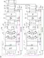
图1是示出实施方式1所涉及的具备多台电力变换装置的电力变换系统的电路结构的图。FIG. 1 is a diagram showing a circuit configuration of a power conversion system including a plurality of power conversion devices according to
图2是示出实施方式1所涉及的电力变换装置的控制电路的概略结构的框图。2 is a block diagram showing a schematic configuration of a control circuit of the power conversion device according to
图3是示出实施方式1所涉及的控制电路的输出电压控制电路的概略结构的框图。3 is a block diagram showing a schematic configuration of an output voltage control circuit of the control circuit according to
图4是示出实施方式1所涉及的电力变换装置的输出电压的特性的图。FIG. 4 is a diagram showing characteristics of the output voltage of the power conversion device according to
图5是在坐标平面上示出实施方式1所涉及的电力变换装置的控制电路使用的函数的图。5 is a diagram showing a function used by a control circuit of the power conversion device according to
图6是示出实施方式1所涉及的利用电力变换装置的频率电力特性的变化的图。FIG. 6 is a diagram showing changes in frequency power characteristics using the power conversion device according to
图7是示出实施方式1所涉及的利用电力变换装置的输出电力的分担的图。FIG. 7 is a diagram showing allocation of output power by the power conversion device according to
图8是在坐标平面上示出实施方式1所涉及的电力变换装置的控制电路使用的函数的图。8 is a diagram showing a function used by a control circuit of the power conversion device according to
图9是示出实施方式2所涉及的电力变换装置的控制电路的概略结构的框图。9 is a block diagram showing a schematic configuration of a control circuit of the power conversion device according to
图10是示出实施方式2所涉及的利用电力变换装置的输出电力的分担的图。FIG. 10 is a diagram showing allocation of output power by the power conversion device according to
(符号说明)(Symbol Description)
1:蓄电池(电力储藏装置);5:直流电源部;10、10a、10b:电力变换装置;20:DC/AC逆变器(电力变换器);40:负载;50、250:控制电路(控制部);100:电力系统。1: battery (power storage device); 5: DC power supply unit; 10, 10a, 10b: power conversion device; 20: DC/AC inverter (power converter); 40: load; 50, 250: control circuit ( Control Department); 100: Power system.
具体实施方式Detailed ways
实施方式1.
图1是示出实施方式1所涉及的将电力变换装置10(10a、10b)连接多台而构成的电力系统100的电路结构的图。FIG. 1 is a diagram showing a circuit configuration of a
图2是示出实施方式1所涉及的电力变换装置10具有的控制电路50的概略结构的框图。2 is a block diagram showing a schematic configuration of a
图3是示出实施方式1所涉及的控制电路50的输出电压控制电路的概略结构的框图。3 is a block diagram showing a schematic configuration of an output voltage control circuit of the
图4是示出实施方式1所涉及的电力变换装置10的DC/AC逆变器20的输出电压的特性的图。FIG. 4 is a diagram showing the characteristics of the output voltage of the DC/
图5是在坐标平面上示出实施方式1所涉及的用于控制电路50导出校正值的函数f(x)的图。FIG. 5 is a diagram showing a function f(x) for deriving a correction value by the
如图1所示,本实施方式1的电力系统100具备结构分别相同的2台电力变换装置10(10a、10b),将各电力变换装置10的交流端子19并联连接于母线41。对母线41连接有负载40,通过使各电力变换装置10运转,能够从各电力变换装置10经由母线41对负载40供给交流电力。As shown in FIG. 1 , the
此外,在本实施方式中,电力系统100包括2台电力变换装置10,但也可以包括3台以上的电力变换装置10。In addition, in the present embodiment, the
电力变换装置10具备直流电源部5、作为电力变换器的DC/AC逆变器20、平滑滤波器23、噪声滤波器30、开关31以及作为控制部的控制电路50。The power conversion device 10 includes a DC
直流电源部5输出直流电力。DC/AC逆变器20将来自该直流电源部5的直流电力变换为交流电力而输出。平滑滤波器23对来自该DC/AC逆变器20的交流电流进行平滑。噪声滤波器30设置于该平滑滤波器23与负载40之间,进行噪声的去除。开关31设置于该噪声滤波器30与负载40之间,能够将DC/AC逆变器20从负载40断开。控制电路50控制DC/AC逆变器20。The DC
各电力变换装置10(10a、10b)的电路结构相同,分别具有相同的控制电路50。Each of the power conversion devices 10 ( 10 a, 10 b ) has the same circuit configuration and has the
直流电源部5具备:作为电力储藏装置的蓄电池1;DC/DC转换器2,将该蓄电池1作为能量源,将蓄电池1的输出电压直接或者变换为期望的电压值而输出;以及电容器3,连接于该DC/DC转换器2的输出端子之间。The DC
DC/AC逆变器20连接于上述电容器3的正负端子之间,是具备4个半导体开关元件Q1、Q2、Q3、Q4的全桥电路。The DC/
半导体开关元件Q1与半导体开关元件Q2的连接点和半导体开关元件Q3与半导体开关元件Q4的连接点分别成为DC/AC逆变器20的交流侧的输出端子。这样,DC/AC逆变器20通过利用来自控制电路50的栅极驱动信号G对各半导体开关元件Q1、Q2、Q3、Q4进行导通/截止控制,将来自电容器3的直流电力变换为交流电力。The connection point between the semiconductor switching element Q1 and the semiconductor switching element Q2 and the connection point between the semiconductor switching element Q3 and the semiconductor switching element Q4 are respectively the output terminals of the AC side of the DC/
半导体开关元件Q1、Q2、Q3、Q4使用以IGBT(Insulated Gate BipolarTransistor,绝缘栅双极晶体管)、MOSFET(Metal Oxide Semiconductor Field EffectiveTransistor,金属氧化物半导体场效应晶体管)等为代表的自消弧形的半导体开关元件。对半导体开关元件分别逆并联地连接有续流二极管。在半导体开关元件使用MOSFET的情况下,也可以利用寄生二极管。The semiconductor switching elements Q1, Q2, Q3, and Q4 use self-extinguishing arc-extinguishing type represented by IGBT (Insulated Gate Bipolar Transistor, Insulated Gate Bipolar Transistor), MOSFET (Metal Oxide Semiconductor Field Effective Transistor, Metal Oxide Semiconductor Field Effect Transistor), etc. Semiconductor switching elements. Freewheeling diodes are connected in anti-parallel to each of the semiconductor switching elements. When a MOSFET is used as a semiconductor switching element, a parasitic diode can also be used.
对DC/AC逆变器20的输出连接平滑滤波器23。平滑滤波器23包括:滤波电抗器21a、21b,一端分别与DC/AC逆变器20的各输出端子连接;以及滤波电容器22,在这些滤波电抗器21a、21b的另一端之间连接。通过平滑滤波器23平滑后的交流电流经由噪声滤波器30和开关31,从电力变换装置10的交流端子19输出到母线41。此外,也可以设为不设置噪声滤波器30、开关31的结构。A smoothing
进而,电力变换装置10具备:第1电流传感器11,检测作为DC/AC逆变器20的输出的在滤波电抗器21a流过的电流Iac1;以及第2电流传感器12,检测利用平滑滤波器23平滑后的交流负载电流Iac2。Furthermore, the power conversion device 10 includes: a first
进而,各电力变换装置10具备:第1直流电压传感器15,检测作为输入到DC/AC逆变器20的直流母线电压的电容器3的电压Vdc;第1交流电压传感器16,检测作为平滑滤波器23的输出且作为施加到滤波电容器22的交流电压的滤波器输出电压值Vac1;以及第2交流电压传感器17,检测作为电力变换装置10的输出且输出到负载40的交流负载电压Vac2。Further, each power conversion device 10 includes: a first
进而,电力变换装置10具备用于检测通过充电或者放电而变化的蓄电池1的充电率等充电状态信息(SOC信息)的SOC传感器18。Further, the power conversion device 10 includes an
由这些各传感器11、12、15~18检测出的值被输入到控制电路50。The values detected by these
接下来,说明DC/AC逆变器20的输出特性和控制电路50的结构以及控制。Next, the output characteristics of the DC/
如图4所示,DC/AC逆变器20的输出电压的频率具有如在有效电力为0W时设为基准频率f0,随着有效电力变大而降低频率那样的频率下降特性。即,控制电路50使用设定的负极性的频率电力特性增益,以与DC/AC逆变器20的输出电力增加相应地使输出电压的频率下降的方式进行控制。因此,上述频率电力特性增益通过具有负的斜率的函数决定。As shown in FIG. 4 , the frequency of the output voltage of the DC/
如图2所示,控制电路50具备电力运算部51、频率调整量运算部53、SOC输出特性运算部52、频率指令运算部54、以及输出电压指令运算部55。As shown in FIG. 2 , the
电力运算部51根据由第2交流电压传感器17得到的交流负载电压Vac2的检测值和由第2电流传感器12得到的交流负载电流Iac2的检测值,计算有效电力P。频率调整量运算部53进行将该求出的有效电力P作为输入、将频率调整量fadj作为输出的比例控制。SOC输出特性运算部52决定在该频率调整量运算部53中使用的频率电力特性增益。频率指令运算部54根据从频率调整量运算部53输出的频率调整量fadj,生成频率指令值finv1。输出电压指令运算部55根据生成的频率指令值finv1,生成DC/AC逆变器20的输出电压指令值V*。The
SOC输出特性运算部52如上所述决定在后级的频率调整量运算部53中的比例控制中使用的频率电力特性增益。在该决定中,SOC输出特性运算部52根据下式(1),针对DC/AC逆变器20的频率电力特性增益(基准增益K),乘以通过函数f决定的校正值f(x)来校正,决定新的频率电力特性增益(第1增益Ksoc1)。The SOC output
Ksoc1=K×f(x) 式(1)Ksoc1=K×f(x) Formula (1)
在此,校正值是通过将由SOC传感器18检测的蓄电池1的SOC信息、例如SOC(%)作为变量x的、函数f唯一地决定的值f(x)。Here, the correction value is a value f(x) uniquely determined by a function f using the SOC information of the
以下,说明利用SOC输出特性运算部52的校正值的导出方法。Hereinafter, a method of deriving the correction value using the SOC output
在SOC输出特性运算部52中,作为将蓄电池1设为放电停止的SOC(第2充电状态),设定有SOCs[%]。例如,在低于充电率30%时蓄电池1的劣化发展的情况或者为了其他用途需要确保充电率30%的情况等下,对将蓄电池1设为放电停止的SOCs设定该30%。In the SOC output
另外,在SOC输出特性运算部52中,作为将蓄电池1设为充电停止的SOC(第1充电状态),设定有SOCc[%]。例如,在超过充电率90%时蓄电池1的劣化发展的情况下,对设为充电停止的SOCc设定该90%。In addition, in the SOC output
另外,在SOC输出特性运算部52中,设定有作为将SOC设为x的校正值的函数f(x)。In addition, in the SOC output
如图5所示,在SOC输出特性运算部52中设定的函数f(x)在由SOC传感器18检测的作为蓄电池1的SOC的x是设定的SOCc[%]以上时决定为实数N1的值,在检测的作为蓄电池1的SOC的x是设定的SOCs[%]以下时决定为比所述N1大的实数N2的值。另外,函数f(x)成为随着检测的作为蓄电池1的SOC的x从SOCs增加至SOCc而从N2逐渐减小至N1的值。As shown in FIG. 5 , the function f(x) set in the SOC output
即,函数f(x)用以下式(2)、式(3)、式(4)表示。That is, the function f(x) is represented by the following formula (2), formula (3), and formula (4).
f(x)=N2 式(2)f(x)=N2 Formula (2)
0[%]≤x≤SOCs[%]0[%]≤x≤SOCs[%]
f(x)=a×x+b 式(3)f(x)=a×x+b Formula (3)
:斜率a=(N1-N2)/(SOCc-SOCs): Slope a=(N1-N2)/(SOCc-SOCs)
:截距b=N2-a×SOCs: intercept b=N2-a×SOCs
SOCs[%]<x<SOCc[%]SOCs[%]<x<SOCc[%]
f(x)=N1式(4)f(x)=N1 formula (4)
SOCc[%]≤x≤100[%]SOCc[%]≤x≤100[%]
这样控制电路50使用上述函数f(x),导出与检测出的蓄电池1的SOC信息、在该情况下为SOC[%]对应起来的校正值。In this way, the
这样通过函数f(x)导出的校正值成为与蓄电池1的SOC信息的增加相应地逐渐减小的值。而且,校正值的最小值是将蓄电池1设为充电停止的第1充电状态(充电率为SOCc[%])下的比0大的实数N1。另外,校正值的最大值是将蓄电池1设为放电停止的第2充电状态(充电率为SOCs[%])下的作为比上述N1大的实数的N2。The correction value derived from the function f(x) in this way becomes a value that gradually decreases in accordance with an increase in the SOC information of the
这样,SOC输出特性运算部52根据上式(1),根据检测出的蓄电池1的SOC信息,对频率电力特性增益(基准增益K)乘以与蓄电池1的SOC信息对应起来设定的校正值来校正,将校正后的基准增益K作为控制DC/AC逆变器20的频率电力特性增益(第1增益Ksoc1)输出给后级的频率调整量运算部53。此外,上述第1增益Ksoc1(频率电力特性增益)的单位是频率/有效电力。In this way, the SOC output
频率调整量运算部53根据下式(5),使用决定的第1增益Ksoc1,决定将由电力运算部51求出的有效电力P作为输入的比例控制中的输出交流电压的频率调整量fadj。The frequency adjustment
频率调整量fadj=Ksoc1×P式(5)Frequency adjustment amount fadj=Ksoc1×P Formula (5)
决定的频率调整量fadj被输出到后级的频率指令运算部54。The determined frequency adjustment amount fadj is output to the frequency
频率指令运算部54根据下式(6),作为DC/AC逆变器20输出的交流电压的频率指令值finv1,计算对基准频率f0加上上述频率调整量fadj后的值。The frequency
finv1=f0+fadjfinv1=f0+fadj
=f0+Ksoc1×P 式(6)=f0+Ksoc1×P Formula (6)
输出电压指令运算部55运算由指定的交流电压的振幅值和通过频率指令值finv1决定的正弦波构成的、DC/AC逆变器20的输出交流电压指令值Vac*。然后,输出电压指令运算部55使用运算出的输出交流电压指令值Vac*和由第2交流电压传感器17检测出的交流负载电压Vac2的值,进行图3所示的运算,进行DC/AC逆变器20的输出电压控制。The output voltage
如图3所示,将检测出的交流负载电压Vac2的值和运算出的输出交流电压指令值Vac*的偏差作为输入的第1控制器60例如通过PI控制(比例控制),作为减小输入的偏差的控制量,输出逆变器输出电流指令值60a。As shown in FIG. 3 , the
作为从该第1控制器60输出的控制量,有直接输出输出电压校正值的方式或者输出逆变器输出电流指令值的方式,在图3中,采用作为控制量输出逆变器输出电流指令值60a的方式。As the control variable output from the
在此,根据滤波电容器22的静电电容值和逆变器输出电压指令值,运算在滤波电容器22流过的电流,作为滤波电容器电流推定值,加到逆变器输出电流指令值60a。Here, based on the capacitance value of the
然后,将在滤波电抗器21a流过的逆变器输出电流检测值Iac1和逆变器输出电流指令值60a的偏差作为输入的第2控制器61例如通过PI控制输出输出电压校正值61a。通过该第2控制器61构成输出输出电压校正值61a的电流次控制。Then, the
也可以对输出电压校正值61a加上从第1交流电压传感器16得到的滤波器输出电压检测值。同样地,也可以根据所述逆变器输出电流指令值Iac1、滤波电抗器21的电感值以及所述频率指令值finv1,运算在滤波电抗器21中产生的电压降,作为滤波电抗器电压降推定值,加到输出电压校正值61a,作为逆变器输出电压指令值V*。The filter output voltage detection value obtained from the first
另外,虽然未图示,也可以对输出电压校正值61a加上所述输出电压指令值。Note that, although not shown, the output voltage command value may be added to the output
通过这样的逆变器输出电压控制,决定DC/AC逆变器20的逆变器输出电压指令值V*。然后,控制电路50依照以PWM控制为代表的DC/AC逆变器的驱动控制,以实现决定的逆变器输出电压指令值V*的方式生成并输出针对半导体开关元件Q1、Q2、Q3、Q4的栅极驱动信号G。Through such inverter output voltage control, the inverter output voltage command value V* of the DC/
图6是示出在实施方式1所涉及的电力变换装置10中控制电路50伴随蓄电池1的SOC的降低而使频率电力特性变化的状态的图。FIG. 6 is a diagram showing a state in which the
如上所述,电力变换装置10对负极性的频率电力特性增益乘以随着由于放电而自身的蓄电池1的SOC减少而逐渐增加的校正值,进行自身的频率电力特性增益的校正。因此,如图6所示,调整输出电压的频率的下降特性的斜率。As described above, the power conversion device 10 corrects its own frequency power characteristic gain by multiplying the negative frequency power characteristic gain by a correction value that gradually increases as the SOC of its
图7是示出在实施方式1所涉及的电力变换装置10a、10b中由于蓄电池1的SOC的差异而各电力变换装置10a、10b的电力分担不同的图。FIG. 7 is a diagram showing that, in the
示出电力系统100具备的2个电力变换装置10a、10b中的、一方的电力变换装置10a具有的蓄电池1的SOC大、且另一方的电力变换装置10b具有的蓄电池1的SOC低的情况下的控制收敛时的频率fb和控制收敛时的有效电力的动作点Pba、Pbb。在通过各电力变换装置10a、10b的控制电路50校正各自的频率电力特性增益时,分别输出了有效电力Pa的电力变换装置10a、10b依照自身的频率电力特性增益,在电力变换装置10a、10b的输出电力的合计成为相同的频率fb下控制进行收敛。在该收敛频率fb下,电力变换装置10a输出的有效电力是Pba,电力变换装置10b输出的有效电力是Pbb,判明进行与SOC的大小对应的电力分担。Among the two
这样各电力变换装置10(10a、10b)分别利用控制电路50独立地校正自身的频率电力特性,并依照该校正后的频率电力特性,由此无需与其他电力变换装置10(10a、10b)进行通信而调整自身的电力分担。In this way, each power conversion device 10 (10a, 10b) independently corrects its own frequency power characteristics by the
在此,关于校正DC/AC逆变器20的频率电力特性的校正值,如图5所示,最小值是将蓄电池1设为充电停止的SOCc下的N1,最大值是将蓄电池1设为放电停止的SOCs下的N2。因此,即使在蓄电池1的充电率从设为放电停止的充电率大幅变动至设为充电停止的充电率的情况下,校正值也在N2至N1的范围内推移。因此,能够将使用该校正值决定的电力变换装置10的频率电力特性的变动范围、即频率的下降特性的斜率的变动范围留在一定范围内。由此,能够抑制电力变换装置10控制收敛时的输出电压的频率大幅变动,并且能够使输出频率稳定地收敛。Here, regarding the correction value for correcting the frequency power characteristic of the DC/
另外,也可以以使电力变换装置10控制收敛时的频率的变动范围收敛于从基准频率f0起2%以内等期望的变动范围内的方式,根据校正前的频率特性增益(基准增益K)的值,决定校正值的上限值N2和下限值N1。通过这样使控制收敛时的输出电压的变动范围留在期望的基准范围内,能够进行与连接的负载设备等的规格对应的运转。In addition, the frequency characteristic gain (reference gain K) before correction may be adjusted based on the frequency characteristic gain (reference gain K) before correction so that the frequency variation range at the time of control convergence of the power conversion device 10 is within a desired variation range within 2% of the reference frequency f0. value to determine the upper limit N2 and lower limit N1 of the correction value. By keeping the fluctuation range of the output voltage at the time of control convergence within the desired reference range in this way, it is possible to perform an operation according to the specifications of the connected load device or the like.
以下,说明校正DC/AC逆变器20的频率电力特性的校正值的其他结构例。Hereinafter, another configuration example for correcting the correction value of the frequency power characteristic of the DC/
图8是在坐标平面上示出实施方式1所涉及的用于控制电路50导出校正值的其他函数g(x)的图。此外,同样在该情况下,x与函数f(x)的情况相同,g(x)的值为校正值。FIG. 8 is a diagram showing another function g(x) used by the
如图8所示,控制电路50将SOCs[%]与SOCc[%]之间划分成2个区间。而且,控制电路50在SOCs[%]与SOCc[%]之间,使用SOCs[%]与SOCt之间的区间中的函数g1(x)和SOCt与SOCc[%]之间的区间中的函数g2(x)这样的、各区间中的校正值随着SOC的增加而逐渐减小的斜率分别不同的2个函数g1(x)、g2(x)。As shown in FIG. 8 , the
这样,通过以在SOCs[%]与SOCc[%]之间,具有随着SOC的增加而分别具有不同的斜率并逐渐减小的至少2个以上的区间的方式设定校正值,能够进行与蓄电池1的特性对应的电力变换装置10的输出电力调整。特别是,通过以使SOCc[%]侧的区间中的校正值的斜率的绝对值小于SOCs[%]侧的区间的校正值的斜率的绝对值的方式设定校正值,在蓄电池1具有高的SOC的SOCct至SOCc[%]的期间,能够维持电力变换装置10的可高输出状态,所以便利性提高。In this way, by setting the correction value so as to have at least two or more sections having different slopes and gradually decreasing as the SOC increases, between the SOCs [%] and the SOCc [%], it is possible to compare the The output power of the power conversion device 10 is adjusted according to the characteristics of the
此外,在控制电路50的SOC输出特性运算部52中设定的SOCc、SOCs不限于预先设定的例子,也可以设为用户能够从外部设定的结构。In addition, the SOCc and SOCs set in the SOC output
在此,关于蓄电池1的长期保存时的劣化,一般满充电时的劣化大,但关于长期保存,根据蓄电池的种类,还存在具有劣化加速比满充电时大的SOC范围带的蓄电池。因此,在控制电路50中,设定指定将蓄电池1设为放电禁止的充电状态信息的范围的放电禁止范围。具体而言,在蓄电池1的劣化加速的SOC范围中,将其中央值的±X%以内设为放电禁止范围。而且,在输入的SOCs是放电禁止范围内时,为了使放电在该放电禁止范围内不停止,以使输入的SOCs成为放电禁止范围外的值的方式对输入的SOCs加上偏置电压或者减去偏置电压来校正,将校正后的值设定为新的放电停止SOCs。通过本设定,由于蓄电池1的长期保存引起的劣化被抑制,所以能够使蓄电池1长寿命化。Here, the deterioration during long-term storage of the
此外,在此前的说明中,关于校正DC/AC逆变器20的频率电力特性的校正值,示出通过控制电路50根据函数f(x)、g(x)导出的值。然而,不限定于此,校正值也可以是在控制电路50中预先设定、记录的数据映射等。关于该数据映射,可以举出选择与蓄电池1的SOC信息对应起来设定的校正值的结构的例子。In addition, in the previous description, regarding the correction value which corrects the frequency electric power characteristic of the DC/
根据如上所述构成的本实施方式的电力变换装置、电力系统,电力变换装置根据蓄电池的检测值,对基准增益乘以与蓄电池的SOC信息对应起来设定的校正值来校正,将校正后的基准增益用作控制电力变换器的第1增益,调整电力变换器的频率的下降特性的斜率。由此,能够进行与电力变换装置的每个蓄电池的SOC对应的输出电力的调整。因此,在电力变换装置具有的自身的蓄电池的SOC低的情况下,能够使具有SOC大的蓄电池的其他电力变换装置承担电力负担来抑制自身的蓄电池的过度的放电,在负载供给结束后保持必要的能量。According to the power conversion device and power system of the present embodiment configured as described above, the power conversion device multiplies the reference gain by the correction value set in accordance with the SOC information of the battery based on the detection value of the battery, and corrects the corrected value. The reference gain is used as the first gain for controlling the power converter, and the slope of the frequency drop characteristic of the power converter is adjusted. Thereby, the output power can be adjusted according to the SOC of each battery of the power conversion device. Therefore, when the SOC of the own battery included in the power conversion device is low, it is possible to suppress excessive discharge of the own battery by causing the other power conversion device having the battery with a high SOC to bear the power burden, and to keep the necessary amount after the load supply ends. energy of.
而且,关于校正值,其最小值是将蓄电池设为充电停止的第1充电状态下的比0大的实数N1,其最大值是将蓄电池设为放电停止的第2充电状态下的比所述N1大的实数N2。这样,通过使电力变换器的频率的下降特性的斜率的变动范围留在一定范围内,即使在蓄电池从设为放电停止的充电率变动至设为充电停止的充电率的情况下,也能够抑制电力变换装置控制收敛时的输出电压的频率的大的变动。另外,能够使电力变换器的输出电压的频率稳定化。In addition, regarding the correction value, the minimum value is a real number N1 larger than 0 in the first state of charge in which the battery is stopped, and the maximum value is the value in the second state of charge in which the battery is in the discharge state. N1 is a large real number N2. In this way, by keeping the fluctuation range of the slope of the frequency drop characteristic of the power converter within a certain range, even when the battery is changed from the charging rate at which the discharge is stopped to the charging rate at which the charging is stopped, it is possible to suppress the change. The power conversion device controls large fluctuations in the frequency of the output voltage at the time of convergence. In addition, the frequency of the output voltage of the power converter can be stabilized.
这样,能够抑制蓄电池成为过放电并且防止连接的负载设备中的不良现象,并且使电力变换装置的运转稳定化。In this way, the operation of the power conversion device can be stabilized while suppressing overdischarge of the storage battery and preventing malfunctions in the connected load equipment.
另外,能够进行以维持为了其他用途(在蓄电池是车载电池的情况下车的驾驶等)决定的SOCs的方式由电力变换装置单体自主地调整输出量的恒定电压运转。因此,在利用装载于作为移动体且保有者不同的电动汽车、混合动力汽车等的蓄电池的情况等下,不需要电力变换装置之间的通信线等通信功能,具有成本降低、便利性提高的优点。另外,不需要电力装置之间的通信功能,所以无需固定蓄电池的接地场所,并且也不需要进行多个蓄电池的一并管理的CPU等。In addition, constant voltage operation in which the output of the power conversion device alone can be adjusted autonomously can be performed so as to maintain SOCs determined for other applications (such as driving of the vehicle when the battery is an on-board battery). Therefore, in the case of using a battery mounted on an electric vehicle, a hybrid vehicle, or the like, which is a mobile body and has different owners, communication functions such as communication lines between power conversion devices are not required, and the cost is reduced and the convenience is improved. advantage. In addition, since the communication function between the power devices is not required, there is no need to fix the grounding place of the storage battery, and there is also no need for a CPU or the like for collective management of a plurality of storage batteries.
另外,校正值也可以以使电力变换器的输出电压的频率的变动范围收敛于如从基本频率起2%以内的范围等的预定的基准范围内的方式设定。这样,能够进行与连接的负载设备的规格对应的运转。In addition, the correction value may be set so that the fluctuation range of the frequency of the output voltage of the power converter falls within a predetermined reference range such as a range within 2% of the base frequency. In this way, operation according to the specifications of the connected load equipment can be performed.
另外,校正值还能够以在将蓄电池设为放电停止的SOCs与设为充电停止的SOCc之间,具有分别具有不同的斜率并随着SOC的增加而逐渐减小的至少2个以上的区间的方式设定。由此,能够进行与蓄电池的特性对应的电力变换装置的输出电力的调整。In addition, the correction value may have at least two or more intervals each having a different slope and gradually decreasing as the SOC increases, between the SOCs at which the battery is stopped from discharging and the SOCc at which the battery is stopped from charging. mode setting. Thereby, the output power of the power conversion device can be adjusted according to the characteristics of the battery.
另外,校正值也可以以在SOCs与SOCc之间的各区间使SOCc侧的区间中的校正值的斜率的绝对值小于SOCs侧的区间的校正值的斜率的绝对值的方式设定。由此,能够在蓄电池具有高的SOC的期间,维持电力变换装置的可高输出状态,便利性提高。In addition, the correction value may be set so that the absolute value of the slope of the correction value in the SOCc-side section is smaller than the absolute value of the slope of the correction value in the SOCs-side section in each section between SOCs and SOCc. This makes it possible to maintain the high-output-capable state of the power conversion device while the battery has a high SOC, thereby improving convenience.
另外,校正值既可以使用在控制电路中预先设定的数据、或者也可以是控制电路使用函数f(x)、g(x)导出。在设为控制电路使用函数f(x)、g(x)来导出校正值的结构时,能够减小控制电路中的存储区域地构成,实现省空间化、低成本化。在控制电路中以成为数据映射结构的方式预先设定并记录校正值的情况下,能够降低电力变换装置的运转中的控制电路的运算负荷。In addition, the correction value may be derived by using data preset in the control circuit, or the control circuit may be derived using functions f(x) and g(x). When the control circuit uses the functions f(x) and g(x) to derive the correction value, the storage area in the control circuit can be reduced, and space saving and cost reduction can be achieved. When the correction value is preset and recorded in the control circuit so as to have a data map structure, the calculation load of the control circuit during the operation of the power conversion device can be reduced.
另外,也可以在控制电路中设定指定将蓄电池设为放电禁止的充电状态信息的范围的放电禁止范围值。在该情况下,控制电路在由用户从外部设定SOCs的情况下,如果该值是放电禁止范围的范围内,则以使设定的SOCs成为放电禁止范围外的值的方式校正。这样,由于蓄电池的长期保存引起的劣化被抑制,能够使蓄电池长寿命化。In addition, a discharge prohibition range value may be set in the control circuit to designate a range of charge state information for prohibiting the discharge of the storage battery. In this case, when the SOCs are externally set by the user, if the value is within the discharge prohibition range, the control circuit corrects the set SOCs to a value outside the discharge prohibition range. In this way, deterioration due to long-term storage of the storage battery is suppressed, and the life of the storage battery can be extended.
此外,以上,示出电力变换装置10具备直流电源部5的结构,但也可以设为电力变换装置10不具备直流电源部5而在外部设置直流电源部5的结构。In addition, although the configuration in which the power conversion device 10 includes the DC
实施方式2.
以下,以与上述实施方式1不同的部位为中心,使用附图,说明本申请的实施方式2。与上述实施方式1同样的部分附加同一符号而省略说明。Hereinafter, the second embodiment of the present application will be described with reference to the drawings, focusing on the points different from the above-described first embodiment. The same parts as those in the first embodiment described above are assigned the same reference numerals, and the description thereof will be omitted.
图9是示出实施方式2所涉及的各电力变换装置10(10a、10b)具有的控制电路250的概略结构的框图。9 is a block diagram showing a schematic configuration of a
在本实施方式中,在控制电路250内,具备将从SOC输出特性运算部输出的第1增益Ksoc1和来自电力运算部51的有效电力P作为输入的额定维持运算部56。In the present embodiment, the
另外,电力系统100与实施方式1所示的例子同样地,是具备2台电力变换装置10(10a、10b)的结构。电力变换装置10a和电力变换装置10b的电路结构相同,分别具有相同的控制电路250。In addition, the
在此,在控制电路250的额定维持运算部56中,设定有DC/AC逆变器20的输出电力的额定值。该额定值能够通过有效电力、视在功率、输出电流有效值、输出电流峰值的任意值设定,在本实施方式中,通过有效电力设定。Here, the rated value of the output power of the DC/
在此,在电力变换装置10a的蓄电池1的SOC高、且电力变换装置10b的蓄电池1的SOC低的情况下,作为负的值的电力变换装置10a的频率电力特性增益(第1增益Ksoc1)大于电力变换装置10b的频率电力特性增益(第1增益Ksoc1)。如上所述,电力变换装置10a和电力变换装置10b的交流输出频率分别收敛于相同的值,所以由于通过频率电力特性增益决定的频率电力特性的差异,分别分担不同的电力。Here, when the SOC of the
在此,SOC大的电力变换装置10a分担的输出电力变大,但存在根据负载40的大小,电力变换装置10a的输出电力超过在额定维持运算部56中设定的额定值的情形。Here, the output power shared by the
电力变换装置10a、10b的各控制电路250的额定维持运算部56具有以将设定的额定值和作为电力变换装置10a、10b的电力运算部51的输出的有效电力P的偏差作为输入的PI控制为代表的未图示的控制器。而且,电力变换装置10a的控制电路250的额定维持运算部56通过控制器,生成用于减小作为来自电力变换装置10a的SOC输出特性运算部52的输出的频率电力特性增益(第1增益Ksoc1)、即增大电力变换装置10a的输出电压的频率的下降特性的斜率的绝对值的控制量KR。The rated
在本实施方式中,控制量KR的值设为比0大的实数,随着有效电力P超过额定值的超过量变大,使KR从0逐渐增加。电力变换装置10a的控制电路250的额定维持运算部56根据下式(7),针对DC/AC逆变器的频率电力特性增益(第1增益Ksoc1)乘以使用控制量KR的额定控制量(1+KR)来校正,决定并输出新的频率电力特性增益(第2增益Ksoc2)。In the present embodiment, the value of the control amount KR is set to a real number larger than 0, and KR is gradually increased from 0 as the amount by which the effective power P exceeds the rated value becomes larger. The rated
Ksoc2=Ksoc1×(1+KR) 式(7)Ksoc2=Ksoc1×(1+KR) Formula (7)
这样,通过设定电力变换装置10a的频率电力特性增益(第2增益Ksoc2),降低作为负的值的频率电力特性增益、即增大输出电压的频率的下降特性的斜率的绝对值。这样,电力变换装置10a能够降低自身的输出分担比率。当然,也可以对所述控制量KR设置上限值。By setting the frequency power characteristic gain (second gain Ksoc2) of the
图10示出电力变换装置10a的控制电路250的额定维持运算部56校正频率电力特性增益(第1增益Ksoc1),通过降低其值的频率电力特性增益(第2增益Ksoc2)变更收敛频率和电力动作点的结果。FIG. 10 shows that the frequency power characteristic gain (first gain Ksoc1) is corrected by the rated
通过由电力变换装置10a的控制电路250最初使用的频率电力特性增益(第1增益Ksoc1),如图10所示收敛于频率f1,在该情况下,电力变换装置10a输出的有效电力Paa超过额定值Pba。The frequency power characteristic gain (first gain Ksoc1) initially used by the
因此,电力变换装置10a的控制电路250的额定维持运算部56使用额定控制量(1+KR),将频率电力特性增益(第1增益Ksoc1)校正为频率电力特性增益(第2增益Ksoc2)。由此,直至电力变换装置10a的输出电力达到额定值Pba的电力期间(有效电力0~Pba的期间)中的、DC/AC逆变器20的频率的下降特性的斜率的绝对值变大。这样,收敛的频率降低到f2,电力变换装置10a输出的有效电力从Paa被控制为额定值Pba,并且关于电力变换装置10b输出的有效电力,以自主地追加输出电力变换装置10a的过负载电力量的方式从Pab追踪控制至Pbb。这样,变更电力变换装置10a和电力变换装置10b的输出电力的分担比。Therefore, the rated
另一方面,在电力变换装置10a的蓄电池1的SOC低、且电力变换装置10b的蓄电池1的SOC高的情况下,作为负的值的电力变换装置10b的频率电力特性增益(第1增益Ksoc1)大于电力变换装置10a的频率电力特性增益(第1增益Ksoc1)。在该情况下,SOC大的电力变换装置10b的输出电力分担变大,但存在根据负载40的大小,电力变换装置10b的输出电力超过在额定维持运算部56中设定的额定值的情形。即使在这样的情况下,也同样地,电力变换装置10b的控制电路250的额定维持运算部56使用额定控制量(1+KR),校正频率电力特性增益。这样,电力变换装置10b输出的有效电力被控制为额定值,以使电力变换装置10a自主地追加输出过负载电力量的方式追踪控制,变更输出电力的分担比。On the other hand, when the SOC of the
以上,关于用于校正频率电力特性增益的额定控制量,如式(7)所示,使用(1+KR),对第1增益Ksoc1乘以该额定控制量(1+KR)而得到第2增益Ksoc2。然而,第1增益Ksoc1的校正方法不限于此。电力变换装置10(10a、10b)的控制电路250也可以通过根据下式(8),从DC/AC逆变器的频率电力特性增益(第1增益Ksoc1)减去额定控制量(KR)来校正,决定新的频率电力特性增益(第2增益Ksoc2)。As described above, with respect to the rated control amount for correcting the frequency-power characteristic gain, as shown in equation (7), using (1+KR), the first gain Ksoc1 is multiplied by the rated control amount (1+KR) to obtain the second Gain Ksoc2. However, the correction method of the first gain Ksoc1 is not limited to this. The
Ksoc2=Ksoc1-KR 式(8)Ksoc2=Ksoc1-KR Formula (8)
在本实施方式中,关于所述额定控制量KR的值,设为比0大的实数,随着有效电力P超过额定值的超过量变大,从0逐渐增加。这样,通过设定频率电力特性增益(第2增益Ksoc2),能够降低作为负的值的频率电力特性增益、即增大输出电压的频率的下降特性的斜率的绝对值。当然,也可以对所述额定控制量KR设置上限值。In the present embodiment, the value of the rated control amount KR is a real number larger than 0, and gradually increases from 0 as the excess of the effective power P over the rated value increases. By setting the frequency power characteristic gain (second gain Ksoc2 ) in this way, the frequency power characteristic gain which is a negative value, that is, the absolute value of the slope of the frequency drop characteristic of the output voltage can be increased. Of course, an upper limit value may also be set for the rated control amount KR.
根据如上所述构成的本实施方式的电力变换装置、电力系统,起到与实施方式1同样的效果,能够抑制输出电压的频率的变动而稳定化,所以能够抑制电力变换装置承担过度的电力负担并且进行稳定的运转。According to the power conversion device and the power system of the present embodiment configured as described above, the same effects as those of the first embodiment can be achieved, and the frequency of the output voltage can be stabilized by suppressing fluctuations, so that the power conversion device can be prevented from receiving an excessive power load. and stable operation.
另外,控制电路在DC/AC逆变器的输出电力超过额定值时,运算增大DC/AC逆变器的频率的下降特性的斜率的绝对值的控制量,通过该控制量校正第1增益Ksoc1,将校正后的第1增益Ksoc1用作控制DC/AC逆变器的第2增益Ksoc2。由此,能够增大直至DC/AC逆变器的输出电力达到额定值的电力期间中的DC/AC逆变器的频率的下降特性的斜率的绝对值。In addition, when the output power of the DC/AC inverter exceeds the rated value, the control circuit calculates a control amount that increases the absolute value of the slope of the frequency drop characteristic of the DC/AC inverter, and corrects the first gain by the control amount Ksoc1, the corrected first gain Ksoc1 is used as the second gain Ksoc2 for controlling the DC/AC inverter. This makes it possible to increase the absolute value of the slope of the frequency drop characteristic of the DC/AC inverter in the power period until the output power of the DC/AC inverter reaches the rated value.
因此,即使在蓄电池的剩余容量大的情况下,也不会承担过度的电力负担,能够在直至DC/AC逆变器的输出电力达到额定值的电力期间使输出电压的频率收敛,而将输出电力抑制为额定值以下。因此,在电力变换装置的电路设计中不需要将设备的电力容量设计得较大,能够实现省空间化以及低成本化。Therefore, even when the remaining capacity of the storage battery is large, the frequency of the output voltage can be converged until the output power of the DC/AC inverter reaches the rated power without taking an excessive power load, and the output Power suppression is below the rated value. Therefore, in the circuit design of the power conversion device, it is not necessary to design the power capacity of the equipment to be large, and space saving and cost reduction can be achieved.
此外,与实施方式1同样地,关于电力系统100,示出由2台电力变换装置10构成的例子,但也可以由3台以上的电力变换装置10构成。In addition, as in the first embodiment, the
本申请记载各种例示性的实施方式以及实施例,但1个或者多个实施方式所记载的各种特征、方式以及功能不限于特定的实施方式的应用,能够单独或者以各种组合应用于实施方式。This application describes various exemplary embodiments and examples, but the various features, forms, and functions described in one or more embodiments are not limited to the application of a specific embodiment, and can be applied alone or in various combinations. implementation.
因此,在本申请公开的技术的范围内,设想未例示的无数的变形例。例如,包括将至少1个构成要素变形的情况、追加的情况或者省略的情况、进而提取至少1个构成要素并与其他实施方式的构成要素组合的情况。Therefore, within the scope of the technology disclosed in the present application, numerous modifications not illustrated can be envisaged. For example, it includes the case where at least one component is modified, the case where it is added, or the case where it is omitted, and the case where at least one component is further extracted and combined with the components in other embodiments.
Claims (12)
Translated fromChineseApplications Claiming Priority (3)
| Application Number | Priority Date | Filing Date | Title |
|---|---|---|---|
| JP2018-093428 | 2018-05-15 | ||
| JP2018093428 | 2018-05-15 | ||
| PCT/JP2019/011072WO2019220763A1 (en) | 2018-05-15 | 2019-03-18 | Power conversion device and power conversion system |
Publications (2)
| Publication Number | Publication Date |
|---|---|
| CN112106288Atrue CN112106288A (en) | 2020-12-18 |
| CN112106288B CN112106288B (en) | 2023-11-24 |
Family
ID=68540299
Family Applications (1)
| Application Number | Title | Priority Date | Filing Date |
|---|---|---|---|
| CN201980027224.2AActiveCN112106288B (en) | 2018-05-15 | 2019-03-18 | Power conversion device and power conversion system |
Country Status (5)
| Country | Link |
|---|---|
| US (1) | US11349409B2 (en) |
| JP (1) | JP6877640B2 (en) |
| CN (1) | CN112106288B (en) |
| DE (1) | DE112019002444T5 (en) |
| WO (1) | WO2019220763A1 (en) |
Cited By (1)
| Publication number | Priority date | Publication date | Assignee | Title |
|---|---|---|---|---|
| TWI881388B (en)* | 2022-07-20 | 2025-04-21 | 日商三菱電機股份有限公司 | Distributed power source integrated management device, power conversion device, power system management system, distributed power source management method and recording medium |
Families Citing this family (4)
| Publication number | Priority date | Publication date | Assignee | Title |
|---|---|---|---|---|
| CN110912231B (en)* | 2019-12-04 | 2021-04-13 | 阳光电源股份有限公司 | Method and system for judging disconnection of storage battery |
| EP3993215A1 (en)* | 2020-10-29 | 2022-05-04 | Wobben Properties GmbH | Dynamic frt bands for wind turbines |
| JP7174178B1 (en) | 2022-03-11 | 2022-11-17 | 東京瓦斯株式会社 | Controller and program |
| JP7597285B2 (en)* | 2022-04-07 | 2024-12-10 | ダーフォン エレクトロニクス コーポレイション | Power Conversion Systems |
Citations (5)
| Publication number | Priority date | Publication date | Assignee | Title |
|---|---|---|---|---|
| CN1118949A (en)* | 1994-04-25 | 1996-03-20 | 松下电工株式会社 | Inverter AC power supply |
| JP2001320881A (en)* | 2000-05-02 | 2001-11-16 | Hitachi Ltd | Control device for power converter |
| WO2014103192A1 (en)* | 2012-12-27 | 2014-07-03 | 川崎重工業株式会社 | Combined power generation system equipped with power conversion device |
| CN107086597A (en)* | 2016-02-16 | 2017-08-22 | 施耐德电器工业公司 | The control method of virtual synchronous generator |
| WO2017179306A1 (en)* | 2016-04-11 | 2017-10-19 | 株式会社日立産機システム | Power conversion device |
Family Cites Families (7)
| Publication number | Priority date | Publication date | Assignee | Title |
|---|---|---|---|---|
| JP5939886B2 (en) | 2012-05-18 | 2016-06-22 | 大成建設株式会社 | Earthquake motion convergence judgment system |
| JP5929943B2 (en)* | 2014-02-21 | 2016-06-08 | トヨタ自動車株式会社 | Power conversion device and power conversion method |
| JP6455661B2 (en) | 2014-12-24 | 2019-01-23 | 富士電機株式会社 | Independent operation system |
| JP2016123243A (en) | 2014-12-25 | 2016-07-07 | パナソニックIpマネジメント株式会社 | Dispersion type power supply system and power supply control method |
| US10256747B2 (en) | 2016-01-20 | 2019-04-09 | Mitsubishi Electric Corporation | Electric power conversion device and electric power conversion system |
| EP3425783B1 (en)* | 2016-03-04 | 2021-12-29 | Mitsubishi Electric Corporation | Power conversion device |
| JP6781637B2 (en) | 2017-01-27 | 2020-11-04 | 株式会社日立産機システム | Control method of the cooperation system of storage battery and power converter, and power conditioning system |
- 2019
- 2019-03-18DEDE112019002444.2Tpatent/DE112019002444T5/enactivePending
- 2019-03-18JPJP2020519485Apatent/JP6877640B2/enactiveActive
- 2019-03-18CNCN201980027224.2Apatent/CN112106288B/enactiveActive
- 2019-03-18WOPCT/JP2019/011072patent/WO2019220763A1/ennot_activeCeased
- 2019-03-18USUS16/979,870patent/US11349409B2/enactiveActive
Patent Citations (5)
| Publication number | Priority date | Publication date | Assignee | Title |
|---|---|---|---|---|
| CN1118949A (en)* | 1994-04-25 | 1996-03-20 | 松下电工株式会社 | Inverter AC power supply |
| JP2001320881A (en)* | 2000-05-02 | 2001-11-16 | Hitachi Ltd | Control device for power converter |
| WO2014103192A1 (en)* | 2012-12-27 | 2014-07-03 | 川崎重工業株式会社 | Combined power generation system equipped with power conversion device |
| CN107086597A (en)* | 2016-02-16 | 2017-08-22 | 施耐德电器工业公司 | The control method of virtual synchronous generator |
| WO2017179306A1 (en)* | 2016-04-11 | 2017-10-19 | 株式会社日立産機システム | Power conversion device |
Cited By (1)
| Publication number | Priority date | Publication date | Assignee | Title |
|---|---|---|---|---|
| TWI881388B (en)* | 2022-07-20 | 2025-04-21 | 日商三菱電機股份有限公司 | Distributed power source integrated management device, power conversion device, power system management system, distributed power source management method and recording medium |
Also Published As
| Publication number | Publication date |
|---|---|
| DE112019002444T5 (en) | 2021-02-04 |
| JPWO2019220763A1 (en) | 2020-12-10 |
| WO2019220763A1 (en) | 2019-11-21 |
| JP6877640B2 (en) | 2021-05-26 |
| CN112106288B (en) | 2023-11-24 |
| US20210367531A1 (en) | 2021-11-25 |
| US11349409B2 (en) | 2022-05-31 |
Similar Documents
| Publication | Publication Date | Title |
|---|---|---|
| CN112106288B (en) | Power conversion device and power conversion system | |
| CN112840520B (en) | System, control device, control method for system, and power conversion device | |
| JP6455661B2 (en) | Independent operation system | |
| CN110637403B (en) | Hybrid energy storage system | |
| US10355320B2 (en) | Power storage device for a battery group and connection control of capacitor and switching device | |
| JP6707309B2 (en) | Power supply system | |
| CN113381458B (en) | Method and control device for controlling a power converter | |
| JP2012100487A (en) | Power system stabilizing apparatus | |
| US12143001B2 (en) | Power supply device | |
| WO2012132459A1 (en) | Vehicle charging device | |
| WO2012132430A1 (en) | Vehicle charging device | |
| US10886744B2 (en) | Power conversion system, power supply system and power conversion device | |
| JP7218453B1 (en) | Uninterruptible power system | |
| US12316122B2 (en) | Direct-current power supply and distribution system | |
| JP7525062B2 (en) | Load current distribution adjustment device, load current distribution adjustment method, and load current distribution adjustment program for a power conversion device for a storage battery | |
| JP7755148B2 (en) | Energy Storage System | |
| US20170101028A1 (en) | Electrical source control apparatus | |
| JP2023110252A (en) | Power supply equipment | |
| CN120049592A (en) | Uninterruptible power supply, control method and computer readable storage medium | |
| JP2023076178A (en) | power storage system | |
| JP2025101581A (en) | Control device and control method | |
| HK40043306A (en) | Grid system, control device, control method for grid system, and power conversion device | |
| JP2016226182A (en) | Uninterruptible power supply device |
Legal Events
| Date | Code | Title | Description |
|---|---|---|---|
| PB01 | Publication | ||
| PB01 | Publication | ||
| SE01 | Entry into force of request for substantive examination | ||
| SE01 | Entry into force of request for substantive examination | ||
| GR01 | Patent grant | ||
| GR01 | Patent grant |