CN112105407B - Auto-injector with improved functionality - Google Patents
Auto-injector with improved functionalityDownload PDFInfo
- Publication number
- CN112105407B CN112105407BCN201980024256.7ACN201980024256ACN112105407BCN 112105407 BCN112105407 BCN 112105407BCN 201980024256 ACN201980024256 ACN 201980024256ACN 112105407 BCN112105407 BCN 112105407B
- Authority
- CN
- China
- Prior art keywords
- needle
- auto
- injector
- driver
- screw
- Prior art date
- Legal status (The legal status is an assumption and is not a legal conclusion. Google has not performed a legal analysis and makes no representation as to the accuracy of the status listed.)
- Active
Links
Images


Classifications
- A—HUMAN NECESSITIES
- A61—MEDICAL OR VETERINARY SCIENCE; HYGIENE
- A61M—DEVICES FOR INTRODUCING MEDIA INTO, OR ONTO, THE BODY; DEVICES FOR TRANSDUCING BODY MEDIA OR FOR TAKING MEDIA FROM THE BODY; DEVICES FOR PRODUCING OR ENDING SLEEP OR STUPOR
- A61M5/00—Devices for bringing media into the body in a subcutaneous, intra-vascular or intramuscular way; Accessories therefor, e.g. filling or cleaning devices, arm-rests
- A61M5/178—Syringes
- A61M5/20—Automatic syringes, e.g. with automatically actuated piston rod, with automatic needle injection, filling automatically
- A61M5/2033—Spring-loaded one-shot injectors with or without automatic needle insertion
- A—HUMAN NECESSITIES
- A61—MEDICAL OR VETERINARY SCIENCE; HYGIENE
- A61M—DEVICES FOR INTRODUCING MEDIA INTO, OR ONTO, THE BODY; DEVICES FOR TRANSDUCING BODY MEDIA OR FOR TAKING MEDIA FROM THE BODY; DEVICES FOR PRODUCING OR ENDING SLEEP OR STUPOR
- A61M5/00—Devices for bringing media into the body in a subcutaneous, intra-vascular or intramuscular way; Accessories therefor, e.g. filling or cleaning devices, arm-rests
- A61M5/178—Syringes
- A61M5/31—Details
- A61M5/315—Pistons; Piston-rods; Guiding, blocking or restricting the movement of the rod or piston; Appliances on the rod for facilitating dosing ; Dosing mechanisms
- A61M5/31565—Administration mechanisms, i.e. constructional features, modes of administering a dose
- A61M5/31576—Constructional features or modes of drive mechanisms for piston rods
- A61M5/31583—Constructional features or modes of drive mechanisms for piston rods based on rotational translation, i.e. movement of piston rod is caused by relative rotation between the user activated actuator and the piston rod
- A61M5/31585—Constructional features or modes of drive mechanisms for piston rods based on rotational translation, i.e. movement of piston rod is caused by relative rotation between the user activated actuator and the piston rod performed by axially moving actuator, e.g. an injection button
- A—HUMAN NECESSITIES
- A61—MEDICAL OR VETERINARY SCIENCE; HYGIENE
- A61M—DEVICES FOR INTRODUCING MEDIA INTO, OR ONTO, THE BODY; DEVICES FOR TRANSDUCING BODY MEDIA OR FOR TAKING MEDIA FROM THE BODY; DEVICES FOR PRODUCING OR ENDING SLEEP OR STUPOR
- A61M5/00—Devices for bringing media into the body in a subcutaneous, intra-vascular or intramuscular way; Accessories therefor, e.g. filling or cleaning devices, arm-rests
- A61M5/178—Syringes
- A61M5/31—Details
- A61M5/32—Needles; Details of needles pertaining to their connection with syringe or hub; Accessories for bringing the needle into, or holding the needle on, the body; Devices for protection of needles
- A61M5/3205—Apparatus for removing or disposing of used needles or syringes, e.g. containers; Means for protection against accidental injuries from used needles
- A61M5/321—Means for protection against accidental injuries by used needles
- A61M5/3243—Means for protection against accidental injuries by used needles being axially-extensible, e.g. protective sleeves coaxially slidable on the syringe barrel
- A61M5/326—Fully automatic sleeve extension, i.e. in which triggering of the sleeve does not require a deliberate action by the user
- A—HUMAN NECESSITIES
- A61—MEDICAL OR VETERINARY SCIENCE; HYGIENE
- A61M—DEVICES FOR INTRODUCING MEDIA INTO, OR ONTO, THE BODY; DEVICES FOR TRANSDUCING BODY MEDIA OR FOR TAKING MEDIA FROM THE BODY; DEVICES FOR PRODUCING OR ENDING SLEEP OR STUPOR
- A61M5/00—Devices for bringing media into the body in a subcutaneous, intra-vascular or intramuscular way; Accessories therefor, e.g. filling or cleaning devices, arm-rests
- A61M5/50—Devices for bringing media into the body in a subcutaneous, intra-vascular or intramuscular way; Accessories therefor, e.g. filling or cleaning devices, arm-rests having means for preventing re-use, or for indicating if defective, used, tampered with or unsterile
- A61M5/5086—Devices for bringing media into the body in a subcutaneous, intra-vascular or intramuscular way; Accessories therefor, e.g. filling or cleaning devices, arm-rests having means for preventing re-use, or for indicating if defective, used, tampered with or unsterile for indicating if defective, used, tampered with or unsterile
- A—HUMAN NECESSITIES
- A61—MEDICAL OR VETERINARY SCIENCE; HYGIENE
- A61M—DEVICES FOR INTRODUCING MEDIA INTO, OR ONTO, THE BODY; DEVICES FOR TRANSDUCING BODY MEDIA OR FOR TAKING MEDIA FROM THE BODY; DEVICES FOR PRODUCING OR ENDING SLEEP OR STUPOR
- A61M5/00—Devices for bringing media into the body in a subcutaneous, intra-vascular or intramuscular way; Accessories therefor, e.g. filling or cleaning devices, arm-rests
- A61M5/178—Syringes
- A61M5/20—Automatic syringes, e.g. with automatically actuated piston rod, with automatic needle injection, filling automatically
- A61M2005/206—With automatic needle insertion
- A—HUMAN NECESSITIES
- A61—MEDICAL OR VETERINARY SCIENCE; HYGIENE
- A61M—DEVICES FOR INTRODUCING MEDIA INTO, OR ONTO, THE BODY; DEVICES FOR TRANSDUCING BODY MEDIA OR FOR TAKING MEDIA FROM THE BODY; DEVICES FOR PRODUCING OR ENDING SLEEP OR STUPOR
- A61M5/00—Devices for bringing media into the body in a subcutaneous, intra-vascular or intramuscular way; Accessories therefor, e.g. filling or cleaning devices, arm-rests
- A61M5/178—Syringes
- A61M5/20—Automatic syringes, e.g. with automatically actuated piston rod, with automatic needle injection, filling automatically
- A61M2005/2073—Automatic syringes, e.g. with automatically actuated piston rod, with automatic needle injection, filling automatically preventing premature release, e.g. by making use of a safety lock
- A—HUMAN NECESSITIES
- A61—MEDICAL OR VETERINARY SCIENCE; HYGIENE
- A61M—DEVICES FOR INTRODUCING MEDIA INTO, OR ONTO, THE BODY; DEVICES FOR TRANSDUCING BODY MEDIA OR FOR TAKING MEDIA FROM THE BODY; DEVICES FOR PRODUCING OR ENDING SLEEP OR STUPOR
- A61M5/00—Devices for bringing media into the body in a subcutaneous, intra-vascular or intramuscular way; Accessories therefor, e.g. filling or cleaning devices, arm-rests
- A61M5/178—Syringes
- A61M5/31—Details
- A61M2005/3143—Damping means for syringe components executing relative movements, e.g. retarders or attenuators slowing down or timing syringe mechanisms
- A—HUMAN NECESSITIES
- A61—MEDICAL OR VETERINARY SCIENCE; HYGIENE
- A61M—DEVICES FOR INTRODUCING MEDIA INTO, OR ONTO, THE BODY; DEVICES FOR TRANSDUCING BODY MEDIA OR FOR TAKING MEDIA FROM THE BODY; DEVICES FOR PRODUCING OR ENDING SLEEP OR STUPOR
- A61M5/00—Devices for bringing media into the body in a subcutaneous, intra-vascular or intramuscular way; Accessories therefor, e.g. filling or cleaning devices, arm-rests
- A61M5/178—Syringes
- A61M5/31—Details
- A61M5/315—Pistons; Piston-rods; Guiding, blocking or restricting the movement of the rod or piston; Appliances on the rod for facilitating dosing ; Dosing mechanisms
- A61M5/31511—Piston or piston-rod constructions, e.g. connection of piston with piston-rod
- A61M2005/3152—Piston or piston-rod constructions, e.g. connection of piston with piston-rod including gearings to multiply or attenuate the piston displacing force
- A—HUMAN NECESSITIES
- A61—MEDICAL OR VETERINARY SCIENCE; HYGIENE
- A61M—DEVICES FOR INTRODUCING MEDIA INTO, OR ONTO, THE BODY; DEVICES FOR TRANSDUCING BODY MEDIA OR FOR TAKING MEDIA FROM THE BODY; DEVICES FOR PRODUCING OR ENDING SLEEP OR STUPOR
- A61M5/00—Devices for bringing media into the body in a subcutaneous, intra-vascular or intramuscular way; Accessories therefor, e.g. filling or cleaning devices, arm-rests
- A61M5/178—Syringes
- A61M5/31—Details
- A61M5/32—Needles; Details of needles pertaining to their connection with syringe or hub; Accessories for bringing the needle into, or holding the needle on, the body; Devices for protection of needles
- A61M5/3205—Apparatus for removing or disposing of used needles or syringes, e.g. containers; Means for protection against accidental injuries from used needles
- A61M5/321—Means for protection against accidental injuries by used needles
- A61M5/3243—Means for protection against accidental injuries by used needles being axially-extensible, e.g. protective sleeves coaxially slidable on the syringe barrel
- A61M5/326—Fully automatic sleeve extension, i.e. in which triggering of the sleeve does not require a deliberate action by the user
- A61M2005/3267—Biased sleeves where the needle is uncovered by insertion of the needle into a patient's body
- A—HUMAN NECESSITIES
- A61—MEDICAL OR VETERINARY SCIENCE; HYGIENE
- A61M—DEVICES FOR INTRODUCING MEDIA INTO, OR ONTO, THE BODY; DEVICES FOR TRANSDUCING BODY MEDIA OR FOR TAKING MEDIA FROM THE BODY; DEVICES FOR PRODUCING OR ENDING SLEEP OR STUPOR
- A61M2205/00—General characteristics of the apparatus
- A61M2205/58—Means for facilitating use, e.g. by people with impaired vision
- A61M2205/583—Means for facilitating use, e.g. by people with impaired vision by visual feedback
- A61M2205/584—Means for facilitating use, e.g. by people with impaired vision by visual feedback having a color code
Landscapes
- Health & Medical Sciences (AREA)
- Engineering & Computer Science (AREA)
- Hematology (AREA)
- Anesthesiology (AREA)
- Biomedical Technology (AREA)
- Heart & Thoracic Surgery (AREA)
- Vascular Medicine (AREA)
- Life Sciences & Earth Sciences (AREA)
- Animal Behavior & Ethology (AREA)
- General Health & Medical Sciences (AREA)
- Public Health (AREA)
- Veterinary Medicine (AREA)
- Environmental & Geological Engineering (AREA)
- Infusion, Injection, And Reservoir Apparatuses (AREA)
Abstract
Translated fromChinese
Description
Translated fromChinese技术领域technical field
本发明涉及一种自动注射器,通过所述自动注射器能够作为自我治疗注射固定剂量的药物,并且在自动注射器被触发之后,通过所述自动注射器作为连续的序列自动地执行将针头暴露于可使用的位置、药物的注射以及将针头缩回到不可使用的位置。The present invention relates to an auto-injector by which a fixed dose of medicament can be injected as self-therapy, and by which, after the auto-injector is triggered, exposing the needle to a usable needle is automatically performed as a continuous sequence. location, injection of medication, and retracting the needle into an unusable position.
背景技术Background technique
在过去的二十年中,自动注射器的使用每年都在显著增加,因为它们具有以下优点:它们允许患者不用医生或护士就可以进行他们的药物治疗。对于这种类型的自动注射器,自动的针头插入、注射和针头缩回是最新技术,并且新的自动注射器定期进入市场。由于这类自动注射器的使用者经常是初次使用者,因此必不可少的是,自动注射器易于使用,运行平稳且可靠,但是不幸的是,市场上的许多自动注射器并非如此。The use of auto-injectors has increased significantly each year over the past two decades because they have the advantage that they allow patients to administer their medication without a doctor or nurse. For this type of auto-injector, automatic needle insertion, injection, and needle retraction are state-of-the-art, and new auto-injectors regularly enter the market. Since users of this type of auto-injector are often first-time users, it is essential that the auto-injector be easy to use, operate smoothly and reliably, which unfortunately is not the case with many auto-injectors on the market.
对于初次使用者,将药物注射到他自己身体的动作可能会非常紧张,因此,自动注射器易于理解和操作是非常重要的,因为紧张的情况可能导致不正确使用自动注射器,并有遭受误治的风险。同样重要的是,以正确的注射速度平稳地进行注射,并且不伴有刺耳和高声的声响,以防止注射引起疼痛或不必要的惊慌。最后,自动注射器应每次工作,以防止这种类型的自动注射器带来不确定性和误解。For a first-time user, the act of injecting the drug into his own body can be very stressful, therefore, it is important that the auto-injector is easy to understand and operate, as stressful situations can lead to incorrect use of the auto-injector and risk of mistreatment risk. It is also important that the injection is performed smoothly and at the correct injection speed and without screeching and loud noises to prevent the injection from causing pain or unnecessary panic. Finally, the auto-injector should work every time to prevent the uncertainty and misunderstanding that this type of auto-injector brings.
自动注射器的最常见问题是操作不直观和使用指令复杂,在将针头插入正确的深度之前开始药物排出,药物的太快注射,并且在针头缩回之后,当自动注射器从一个功能序列切换到另一个功能序列时,它发出很大的噪声、以及特别是与回缩针头有关的自动注射器的故障。The most common problems with the auto-injector are unintuitive operation and complicated instructions to use, starting the drug expelling before the needle is inserted to the correct depth, injecting the drug too quickly, and when the auto-injector switches from one functional sequence to another after the needle is retracted. During a functional sequence, it emits loud noises and malfunctions of the auto-injector especially related to retracting the needle.
相关技术的描述Description of Related Art
自动注射器的专利领域非常拥挤,但是文献WO9535126,EP0516473、WO2005115509、WO2005115511、WO2005115513、WO2005115516、WO2007066152、WO2008005315、WO2011101377、EP2468329和EP2129416对本领域中的现有技术进行了很好的描述。这些文献中的一些将在下文中进一步描述。The patent field for auto-injectors is very crowded, but the state of the art is well described in documents WO9535126, EP0516473, WO2005115509, WO2005115511, WO2005115513, WO2005115516, WO2007066152, WO2008005315, WO2011101377, EP2468329 and EP216. Some of these documents are described further below.
在WO2005115516中,描述了一种自动注射器,其包括适于容纳带有中空针头的针筒的壳体。壳体包括用于将针筒从其中针头从壳体伸出的伸出位置偏置到其中针头被容纳在壳体内的缩回位置的装置。自动注射器还包括可压缩弹簧,由弹簧作用的驱动器继而作用于针筒,以通过针头将其内容物排出;解耦机构,当驱动器前进到标称解耦位置时所述解耦机构被激活,以允许自动注射器的第一组件相对于第二组件运动;释放机构,当所述第一组件相对于第二组件到达标称释放位置时所述释放机构被激活,以从弹簧的作用下释放针筒,随后,偏压装置将针筒恢复到其缩回位置,并且高粘性流体正在抑制所述第一组件相对于第二组件的运动,从而在激活解耦机构之后延迟了针筒的释放,以便在释放针筒以使其缩回之前将针筒的剩余内容物排出。In WO2005115516, an auto-injector is described comprising a housing adapted to accommodate a syringe with a hollow needle. The housing includes means for biasing the barrel from an extended position in which the needle extends from the housing to a retracted position in which the needle is received within the housing. The auto-injector also includes a compressible spring, which in turn acts on the barrel by the spring-operated driver to expel its contents through the needle, and a decoupling mechanism that is activated when the driver is advanced to the nominal decoupling position, to allow movement of the first assembly of the auto-injector relative to the second assembly; a release mechanism that is activated when the first assembly reaches a nominal release position relative to the second assembly to release the needle from the spring the barrel, then the biasing device restores the barrel to its retracted position, and the highly viscous fluid is inhibiting movement of the first assembly relative to the second assembly, delaying the release of the barrel after activation of the decoupling mechanism, This allows the remaining contents of the syringe to be expelled before releasing the syringe to retract it.
在WO2008005315中,描述了用于向使用者皮下注射物质的另一种自动注射器,所述自动注射器包括:壳体;针筒,其具有保持物质的筒部;以及针头,其可运动地设置在壳体中;以及柱塞,其用于密封筒部并选择性地向物质施加压力以迫使物质通过针头;针筒致动组件,其用于首先将针筒移向壳体的第一端,以使针头露出,并随后向柱塞施加压力;以及可压缩弹簧,其用于将针筒致动组件朝壳体的近端偏置,所述弹簧设置在针筒致动组件上的凸缘和壳体的远端之间。In WO2008005315, another auto-injector for subcutaneously injecting a substance to a user is described, the auto-injector comprising: a housing; a barrel having a barrel portion holding the substance; and a needle movably disposed at in the housing; and a plunger for sealing the barrel and selectively applying pressure to the substance to force the substance through the needle; a syringe actuation assembly for first moving the syringe toward the first end of the housing, to expose the needle and subsequently apply pressure to the plunger; and a compressible spring for biasing the syringe actuation assembly toward the proximal end of the housing, the spring being provided on a flange on the syringe actuation assembly and the distal end of the housing.
所描述的两个自动注射器都利用压缩弹簧来插入和缩回针头并进行注射,这反过来需要大量的耦合和锁定/解锁特征,才能在不同的操作序列之间进行转换,并因此增加了发生故障的风险。其次,两个自动注射器都推动柱塞以向前运动针筒,这增加了在针头完全插入之前就开始注射的风险。此外,压缩弹簧往往会产生非常不平滑的操作。Both of the auto-injectors described utilize compression springs to insert and retract the needle and inject, which in turn requires extensive coupling and locking/unlocking features to transition between different sequences of operations, and thus increases the occurrence of risk of failure. Second, both auto-injectors push the plunger to move the barrel forward, which increases the risk of starting an injection before the needle is fully inserted. Additionally, compression springs tend to produce very rough operation.
WO2011101377中描述的自动注射器利用扭转弹簧来插入和缩回针头并进行注射。所述自动注射器包括细长的外壳体,所述外壳体被布置为容纳具有中空针头和柱塞的针筒,所述外壳体具有远端和近端,该近端具有旨在施加在注射部位上的孔口。所述针筒相对于外壳体可滑动地布置,并且自动注射器还包括扭转弹簧,所述扭转弹簧能够在激活时:1)通过孔口将针头推入前进位置,和2)操作针筒以提供药物剂量,并且最后3)在递送药物后以及将针筒从前进位置解锁后,将带有针头的针筒缩回至覆盖位置。致动装置布置成在手动操作之前将弹簧锁定在加压状态,并且能够在手动操作时释放扭转弹簧以进行注射,扭转弹簧在外壳体的一端处接地并且在可绕纵向轴线旋转的第一齿轮构件中的另一端处接地。在第二齿轮构件被阻止旋转并被耦合至柱塞以便将其推向近端的情况下,第一齿轮构件布置成在旋转时将该第二齿轮构件朝着近端平移,并且,在手动操作之前,第一齿轮构件与致动装置接合,以防止手动操作时旋转并从致动装置脱离。由于扭转弹簧,该自动注射器与其他所述的自动注射器相比将提供更平稳的注射,但是该自动注射器仍包括锁定/解锁特征,因此增加了不同功能序列之间的故障风险。The auto-injector described in WO2011101377 utilizes a torsion spring to insert and retract the needle and inject. The autoinjector includes an elongated outer housing arranged to receive a barrel having a hollow needle and a plunger, the outer housing having a distal end and a proximal end, the proximal end having an intended application at an injection site. orifice. The syringe is slidably disposed relative to the outer housing, and the autoinjector further includes a torsion spring capable of, upon activation: 1) urging the needle through the orifice into an advanced position, and 2) operating the syringe to provide drug dose and finally 3) retract the syringe with needle to the covering position after delivering the drug and unlocking the syringe from the advanced position. The actuating device is arranged to lock the spring in a pressurized state prior to manual operation and to release the torsion spring for injection during manual operation, the torsion spring being grounded at one end of the outer housing and in a first gear rotatable about the longitudinal axis Ground at the other end in the member. With the second gear member prevented from rotating and coupled to the plunger for urging it proximally, the first gear member is arranged to translate the second gear member proximally when rotated, and, when manually Prior to operation, the first gear member is engaged with the actuating device to prevent rotation and disengagement from the actuating device during manual operation. Due to the torsion spring, the auto-injector will provide a smoother injection than other described auto-injectors, but the auto-injector still includes a locking/unlocking feature, thus increasing the risk of failure between different functional sequences.
发明内容SUMMARY OF THE INVENTION
本发明的目的是提供一种自动注射器,其不包括用于主动地启用和/或禁用自动注射器的不同序列的任何主动模式转换元件,并且其在时间上清楚地区分了针头插入注射和针头缩回,并且序列没有重叠。It is an object of the present invention to provide an auto-injector that does not include any active mode switching elements for actively enabling and/or disabling different sequences of auto-injectors, and that clearly distinguishes needle insertion injection and needle retraction in time back, and the sequences do not overlap.
本发明涉及一种自动注射器,所述自动注射器限定主轴并包括:The present invention relates to an automatic injector defining a main shaft and comprising:
壳体,case,
针筒组件,所述针筒组件包括带有中空针头和柱塞的容器,以及要注射的药物,a syringe assembly comprising a container with a hollow needle and plunger, and a drug to be injected,
第一弹簧装置,first spring device,
驱动器,driver,
螺杆,screw,
触发器,所述触发器适于在激活之后启动自动注射器的功能序列,其中,所述功能序列包括:在所述壳体中运动所述针筒组件以将所述针头暴露于可可用的位置;使药物通过所述针头排出;在所述壳体中运动所述针筒组件以将所述针头缩回至不可使用的位置;以及其中,所述螺杆在注射过程中适于通过所述第一弹簧装置并经由所述驱动器使所述容器中的所述柱塞运动以排出药物,并且其中所述第一弹簧装置是扭转弹簧,所述扭转弹簧至少在药物排出和针头缩回期间,作用在驱动器上并使驱动器在所述壳体中向上运动来远离所述壳体的针头端。a trigger adapted to initiate a sequence of functions of the auto-injector after activation, wherein the sequence of functions includes moving the syringe assembly in the housing to expose the needle to a usable position expelling medication through the needle; moving the syringe assembly in the housing to retract the needle to an unusable position; and wherein the screw is adapted to pass through the first during injection a spring means moves the plunger in the container via the driver to expel the drug, and wherein the first spring means is a torsion spring that acts at least during drug expelling and needle retraction On the driver and move the driver up in the housing away from the needle end of the housing.
通过使驱动器在自动注射器中向上运动,提供了用于缩回针头的新选项,因此不需要特定的模式转换机构。By moving the driver upward in the auto-injector, a new option for retracting the needle is provided, thus eliminating the need for a specific mode switching mechanism.
在另一实施例中,根据本发明的自动注射器具有在一端固定到针筒组件而在另一端固定到驱动器的弹簧装置。通过这种方式,在针筒组件运动以将针头缩回到不可使用的位置的过程中,防止了扭转弹簧的收缩或压缩。In another embodiment, an auto-injector according to the present invention has spring means secured to the syringe assembly at one end and to the driver at the other end. In this way, contraction or compression of the torsion spring is prevented during movement of the syringe assembly to retract the needle to the unusable position.
在又一实施例中,螺杆和驱动器旋转地连接,从而它们一起旋转但被允许伸缩,并使得柱塞的运动是螺杆在第一螺纹接合中相对于针筒组件的旋转运动的结果,或者,螺杆和驱动器以螺纹接合方式接合,并且柱塞的运动是驱动器在第一螺纹接合中相对于螺杆旋转运动的结果。In yet another embodiment, the screw and driver are rotationally connected such that they rotate together but are allowed to telescopic and such that the movement of the plunger is the result of rotational movement of the screw relative to the barrel assembly in the first thread engagement, or, The screw and driver are engaged in threaded engagement, and the movement of the plunger is the result of rotational movement of the driver relative to the screw in the first threaded engagement.
通过在螺纹接合中相对于其他元件向下旋转螺杆,螺杆的轴向运动更加平滑和精确。By rotating the screw downward relative to the other elements in the threaded engagement, the axial movement of the screw is smoother and more precise.
在又一实施例中,驱动器至少在药物排出期间在第二螺纹接合中与壳体接合,并且第二螺纹接合在排出之后立即脱离,以允许驱动器和针筒组件借助于第二弹簧装置运动进入壳体中来到达针头不可使用的位置。通过螺纹的脱离而触发针头的缩回,确保了缩回操作中涉及的部件不会阻塞。In yet another embodiment, the driver is engaged with the housing in a second threaded engagement at least during expelling of the drug, and the second threaded engagement is disengaged immediately after expelling to allow the driver and syringe assembly to move into by means of the second spring means into the housing to a position where the needle cannot be used. The retraction of the needle is triggered by the disengagement of the thread, ensuring that the parts involved in the retraction operation are not blocked.
在又一实施例中,在针头暴露期间,针筒组件和驱动器在第三螺纹接合中接合,并且针筒组件的运动是针筒组件和驱动器之间的相对旋转运动的结果。通过使旋转运动和螺纹执行针筒组件的运动,能够通过螺纹的螺距来控制速度和速度变化,并且可能通过将螺纹设计为可变螺距螺纹来控制速度和速度变化。In yet another embodiment, the syringe assembly and the driver are engaged in a third threaded engagement during needle exposure, and the movement of the syringe assembly is the result of relative rotational movement between the syringe assembly and the driver. By having the rotational movement and the thread perform the movement of the barrel assembly, the speed and speed variation can be controlled by the pitch of the thread, and possibly by designing the thread as a variable pitch thread.
在又一实施例中,在通过触发器启动之后,针筒组件借助于可压缩弹簧而朝着壳体的针头端运动。如果需要,能够以这种方式提供更快的针头插入。In yet another embodiment, after actuation by the trigger, the syringe assembly is moved toward the needle end of the housing by means of a compressible spring. If desired, faster needle insertion can be provided in this manner.
在又一实施例中,螺纹在螺杆上的长度和位置布置成使得螺杆在第一螺纹接合中的旋转在针头的暴露和缩回期间不会使柱塞在药筒中运动。这样可以确保自动注射器的功能序列之间有明确的分隔,并且在针头的暴露和缩回期间中不会发生药物的排出。In yet another embodiment, the length and position of the threads on the screw are arranged such that rotation of the screw in the engagement of the first thread does not move the plunger in the cartridge during exposure and retraction of the needle. This ensures that there is a clear separation between the functional sequences of the auto-injector and that no expulsion of medication occurs during needle exposure and retraction.
在又一实施例中,在所述驱动器相对于所述针筒组件的轴向运动由所述触发器启动之后,开始所述自动注射器的功能序列。通过简单地将针筒组件推出与驱动器的旋转连接,能够提供简单的触发器系统。In yet another embodiment, the sequence of functions of the auto-injector begins after axial movement of the driver relative to the syringe assembly is initiated by the trigger. By simply pushing the syringe assembly out of the rotational connection with the driver, a simple trigger system can be provided.
在又一实施例中,触发器是可运动地布置在壳体的外部的套筒,并且触发器必须相对于壳体旋转一角度才能够启动自动注射器的功能序列,其中在触发器轴向运动后,启动功能序列。这样就不需要附加的单独的启动机构,以确保自动注射器被意外触发。In yet another embodiment, the trigger is a sleeve movably arranged outside the housing, and the trigger must be rotated by an angle relative to the housing to be able to initiate the function sequence of the auto-injector, wherein the trigger is moved axially After that, start the function sequence. This eliminates the need for an additional separate activation mechanism to ensure that the auto-injector is accidentally triggered.
在又一实施例中,阻尼器可旋转地布置在针筒组件内部,并且在药物排出结束时或在排出之后立即旋转地连接至螺杆,以通过摩擦来减慢螺杆速度。这以非常简单和可靠的方式确保在缩回针头之前,柱塞完全放松并且药物完全排出。In yet another embodiment, the damper is rotatably arranged inside the syringe assembly and is rotationally connected to the screw at the end of drug expelling or immediately after expelling to slow down the screw speed by friction. This ensures in a very simple and reliable way that before retracting the needle, the plunger is fully relaxed and the drug is fully expelled.
本发明的目的能够通过具有扭转弹簧作为用于插入和注射药物的驱动弹簧的自动注射器来实现。具有中空针头并容纳药物的药筒容纳在针筒组件中,所述针筒组件相对于壳体旋转地固定。针筒组件包括具有孔口的药筒载体,所述孔口具有位于药筒的开口上方的螺纹,其中,能够在第一螺纹接合中将抵靠在药筒中的柱塞的螺杆向下拧,以使柱塞在药筒中向下运动并通过针头压出药物。驱动器不是轴向地而是可旋转地与螺杆连接,并且螺杆和驱动器能够相对于彼此伸缩。驱动器在第二螺纹接合中在与针头相对的一端进一步与壳体接合。扭转弹簧在一端固定在针筒组件上,且在另一端固定在驱动器上。针筒组件还包括固定到药筒载体的连接管,并且在触发自动注射器之前,连接管和驱动器以键/槽连接的方式彼此接合,在触发自动注射器后,接着依次进行第三和第四螺纹接合,其中形成第二和第四螺纹接合的螺距相同,并且其中第三螺纹接合中的螺纹的螺距高于第二螺纹接合和第四螺纹接合中的螺纹的螺距。当自动注射器压向注射部位并且触发器套筒相对于壳体运动时,围绕壳体的触发器套筒适于能够将连接管推出与驱动器的键/槽接合。The object of the present invention can be achieved by an automatic injector having a torsion spring as the drive spring for inserting and injecting the drug. A cartridge having a hollow needle and containing a medicament is housed in a syringe assembly that is rotationally fixed relative to the housing. The syringe assembly includes a cartridge carrier having an orifice having threads above the opening of the cartridge, wherein in a first threaded engagement a screw of a plunger that rests in the cartridge can be screwed down, to move the plunger down in the cartridge and force the drug out through the needle. The drive is not axially but rotatably connected to the screw, and the screw and the drive are telescopic relative to each other. The driver is further engaged with the housing at the end opposite the needle in the second threaded engagement. A torsion spring is attached to the syringe assembly at one end and to the driver at the other end. The syringe assembly also includes a connecting tube secured to the cartridge carrier, and prior to triggering the auto-injector, the connecting tube and the driver engage each other in a key/slot connection, followed by a third and fourth thread after triggering the auto-injector A joint in which the pitches forming the second and fourth threaded joints are the same, and in which the pitch of the threads in the third threaded joint is higher than the pitch of the threads in the second and fourth threaded joints. The trigger sleeve surrounding the housing is adapted to be able to push the connecting tube out of engagement with the key/slot of the driver when the auto-injector is pressed against the injection site and the trigger sleeve is moved relative to the housing.
当使用者通过将自动注射器推向皮肤而触发自动注射器后,连接管与驱动器之间的键/槽连接因此被推开而脱离接合,连接管进入与驱动器的第三螺纹接合,并且扭转弹簧旋转驱动器,由于螺纹接合使连接管运动,从而使针筒组件向前运动以露出针头并将其插入皮下组织。此后,连接管和驱动器进入第四螺纹接合,并且由于驱动器由于与壳体的第二螺纹接合而向上运动,并且由于第二和第四螺纹接合的螺纹具有相同的螺距,所以针筒组件不会运动。但是,由于与药筒载体第一螺纹接合,螺杆将在药筒中向下旋转,并且注射药物。当注射药筒中的内容物时,驱动器和壳体之间的第二次螺纹接合旋转而脱离接合,复位弹簧将针筒组件推回到自动注射器中,直到针筒组件被触发器套筒停止且针头被完全缩回。When the user triggers the auto-injector by pushing the auto-injector against the skin, the key/slot connection between the connecting tube and the driver is thus pushed out of engagement, the connecting tube enters the third threaded engagement with the driver, and the torsion spring rotates The driver, due to the threaded engagement, moves the connecting tube to move the syringe assembly forward to expose the needle and insert it into the subcutaneous tissue. Thereafter, the connecting tube and driver enter the fourth threaded engagement, and since the driver moves upward due to engagement with the second threaded engagement of the housing, and since the threads of the second and fourth threaded engagements have the same pitch, the syringe assembly does not sports. However, due to engagement with the first thread of the cartridge carrier, the screw will rotate downward in the cartridge and inject the drug. When the contents of the cartridge are injected, the second threaded engagement between the driver and housing rotates out of engagement, the return spring pushes the syringe assembly back into the auto-injector until the syringe assembly is stopped by the trigger sleeve and The needle is fully retracted.
为了确保在缩回针头之前排出全部内容物,螺杆旋转连接到阻尼器,该阻尼器会在驱动器脱离壳体的螺纹之前减慢螺杆和驱动器的旋转速度。阻尼器位于药筒载体内部,并在阻尼器和药筒载体之间涂抹高粘度油脂或其他摩擦化合物或材料。To ensure that the entire contents are expelled before retracting the needle, the screw is rotationally connected to a damper that slows the rotation of the screw and driver before the driver disengages from the threads of the housing. The damper is located inside the cartridge carrier and a high viscosity grease or other friction compound or material is applied between the damper and the cartridge carrier.
为了使触发器套筒能够触发自动注射器,必须将触发器套筒相对于自动注射器从锁定位置旋转到启动位置。这是为了确保在操作过程中不会意外触发自动注射器。In order for the trigger sleeve to trigger the auto-injector, the trigger sleeve must be rotated relative to the auto-injector from the locked position to the activated position. This is to ensure that the auto-injector is not accidentally triggered during operation.
附图说明Description of drawings
以下,参照附图进一步详细地描述本发明,其中Hereinafter, the present invention will be described in further detail with reference to the accompanying drawings, in which
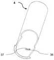
图1示出了根据本发明的自动注射器的透视图。Figure 1 shows a perspective view of an auto-injector according to the present invention.
图2示出了根据本发明的自动注射器的分解图。Figure 2 shows an exploded view of an auto-injector according to the present invention.
图3示出了根据本发明的针筒组件的透视图和局部剖视图。Figure 3 shows a perspective view and a partial cross-sectional view of a syringe assembly in accordance with the present invention.
图4示出了根据本发明的壳体组件的透视图。Figure 4 shows a perspective view of a housing assembly according to the present invention.
图5示意性地示出了根据本发明的准备好使用的自动注射器的垂直截面图。Figure 5 schematically shows a vertical sectional view of an auto-injector ready for use according to the present invention.
图6示意性地示出了根据本发明的自动注射器的垂直截面图,其中触发器被激活,并且针头被暴露。Figure 6 schematically shows a vertical cross-sectional view of an auto-injector according to the present invention with the trigger activated and the needle exposed.
图7示意性地示出了根据本发明的自动注射器的垂直截面图,其中药物已经被注射。Figure 7 schematically shows a vertical cross-sectional view of an auto-injector according to the present invention, wherein a medicament has been injected.
图8示意性地示出了根据本发明的自动注射器的垂直截面图,其中针头已经从暴露位置缩回。Figure 8 schematically shows a vertical cross-sectional view of an auto-injector according to the present invention, wherein the needle has been retracted from the exposed position.
图9示出了根据本发明的药筒载体的透视图。Figure 9 shows a perspective view of a cartridge carrier according to the present invention.
图10示出了根据本发明的触发器套筒的透视图。Figure 10 shows a perspective view of a trigger sleeve according to the present invention.
图11示出了根据本发明的壳体的透视图。Figure 11 shows a perspective view of a housing according to the present invention.
具体实施例specific embodiment
在下文中,主轴一词定义了主要为管状的零件以及整个自动注射器的公共旋转轴。术语“上”和“下”以及“上部的”和“下部的”以及“向上”和“向下”是指附图,并且不一定对应于使用情况。In the following, the term main shaft defines the mainly tubular part and the common axis of rotation of the entire auto-injector. The terms "upper" and "lower" and "upper" and "lower" and "upward" and "downward" refer to the drawings and do not necessarily correspond to usage.
在图1中,示出了根据本发明的自动注射器的透视图。在自动注射器的上部能够看到上壳体11,而在下部能够看到一直延伸到上壳体11的下壳体3。同样,用于查看药筒10的内容物的窗口46也是可见的。在壳体3的外部触发器套筒4是可见的,通过触发器套筒4启动自动注射器的功能序列,并且通过抓握触发器套筒4周围和将自动注射器压向注射部位来操作自动注射器。通过将触发器套筒4从锁定位置到启动位置旋转一角度来准备自动注射器以进行注射,在此之后触发器套筒4相对于壳体3的轴向运动是可能的,这继而将引发暴露针头、注射药物和缩回针头的序列。可替代地,通过移除覆盖壳体和药筒10的下部的盖(未示出)来解锁自动注射器,并且所述盖能够适于同时移除针头护罩(未示出)。In Figure 1, a perspective view of an auto-injector according to the present invention is shown. The
图2示出了根据本发明的自动注射器的分解图,其中自动注射器的所有部件都可见。这些将在功能描述期间提及,尤其是在剖视图没有清楚显示所描述的特征时提及。自动注射器的某些部件固定在一起以作为一个部件起作用,例如,药筒载体12、药筒对准器8、连接管5和具有针头、柱塞和药物的药筒10,这些部件连同螺杆6、柱塞脚15和阻尼器9一起构成了针筒组件1。这可以在图3中看到。下壳体3和上壳体11也固定在一起并作为一个部件起作用,并且在下面将这两个部件一起称为壳体2,并且能够在图4中看到。应该理解的是,这些组件实际上可以根据自动注射器的组装方式来被不同地划分或被划分以形成更多或更少的部件,并且药筒10能够由玻璃或塑料制成并且能够是一独立的部件或与针筒组件1的其他部件集成在一起。Figure 2 shows an exploded view of the auto-injector according to the present invention with all components of the auto-injector visible. These will be mentioned during the functional description, especially when the sectional views do not clearly show the described features. Certain parts of the auto-injector are secured together to function as one part, eg, the
图5示出了根据本发明的自动注射器的截面图。具有药物、中空针头和可运动的柱塞的药筒10保持在针筒组件1的内部中,所述针筒组件1还包括固定于所述药筒载体12并牢固地封闭药筒10的药筒对准器8、固定在药筒载体12上的连接管5、螺杆6、柱塞脚15和阻尼器9。具有螺纹19的螺杆6延伸穿过药筒载体12中的孔口32,并在第一螺纹接合中与螺纹39接合,并且同时螺杆6通过相对于螺杆6旋转的柱塞脚15抵靠在药筒10中的柱塞上。在针头缩回之前,阻尼器9正在减慢螺杆6的旋转速度,以确保全部内容物被排出。这将在后面进一步解释。Figure 5 shows a cross-sectional view of an auto-injector according to the present invention. A
通过螺杆6上的键20(见图2)和在驱动器7内部的槽43,驱动器7不是轴向地而是旋转地与螺杆6连接,并且这两个部件能够彼此伸缩。预紧的扭转弹簧14布置在药筒载体12和驱动器7的外部上,所述扭转弹簧在一端固定到药筒载体12上的凸缘33,而在另一端固定到驱动器7上的凸缘30。从上壳体11的顶板,具有螺纹25的管状突出部24向下突出,并且在第二螺纹接合中与驱动器7的上部内部的螺纹31接合。通过连接管5,针筒组件1通过驱动器7上的键21和在连接器管5内部的槽41在第一轴向范围内与驱动器7连接(见图2),在第二轴向范围内与驱动器7连接,以及,在第三轴向范围内与驱动器7连接,在第二轴向范围内部件以高螺距在键21和螺旋表面27之间的第三螺纹接合中旋转,以及在第三轴向范围内部件在驱动器7外部的螺纹22与连接管5内部的螺纹段26之间的第四螺纹接合中旋转。在驱动器7在第三螺纹接合21/27中旋转期间,螺纹段26在驱动器7上的螺旋段23之间的区域中运动,但是不与螺旋段接触。第二和第四螺纹接合的螺距是相同的,并且它们比第三螺纹接合的螺距小。The
在壳体2的下端中设置有开口18,当触发自动注射器时,针头能够通过所述开口暴露并插入。在针筒组件1和壳体2之间设置了复位弹簧13,所述弹簧将针筒组件1推回到自动注射器中以在注射完药物后将针头藏起,并将针筒组件1朝着在壳体2的顶部中的管状突出部24偏压,使得在管状突出部24和驱动器7之间的第二螺纹接合25/31限定了针筒组件1的轴向位置。在注射药物之后,第二螺纹接合脱离,并且复位弹簧13将针筒组件1推入自动注射器中,使得针头被隐藏。这会在下文中进一步描述。An
布置在壳体2的外侧上的触发器套筒4具有两个朝向主轴线向内突出的突出部36,两个突出部都有更靠近主轴线的较小部分37(见图10)。两个突出部36穿过壳体2中的开口47突出(见图11),并与药筒载体12上的两个突出部34配合,这两个突出部34布置在柔性臂35上(见图9)以简化自动注射器的组装,并锁定针筒组件1使其不相对于壳体2旋转。当触发器套筒4相对于壳体2向下运动时,针筒组件1随之运动,并且驱动器7上的键21(见图2)运动与连接管5上的槽41(参见图2)脱离接合,这导致这两个部件从第一轴向范围运动到第二轴向范围,并且开始插入针头、注射和缩回针头的功能序列。The
接下来将更详细地说明触发自动注射器、插入针头、排出药物和缩回针头的功能序列。图5中示出了根据本发明的自动注射器。触发器套筒4处于其上部位置并且尚未被使用者激活,并且驱动器7上的键21与连接管5中的槽41接合,从而触发器7被锁定以防止其旋转。针头被隐藏并且从开口18缩回距离L1,并且药筒10已满。驱动器7上的螺纹31被复位弹簧13压靠在管状突出部24上的螺纹25上,并且形成第二螺纹接合的这两根螺纹25/31尚未完全接合。还可以看出,一起形成第三螺纹接合的连接管5上的螺纹段26和驱动器7上的螺纹22,也尚未接合。The functional sequence for triggering the auto-injector, inserting the needle, expelling the medication, and retracting the needle will be explained in more detail next. An auto-injector according to the present invention is shown in FIG. 5 . The
在使用者触发自动注射器之前,他必须通过将触发器套筒4旋转一个有限的角度来启动该设备。稍后将进一步解释该操作的细节。Before the user can trigger the auto-injector, he must activate the device by rotating the
在图6中,触发器套筒4已经朝着针头端向下运动,并且由于在触发器套筒4内的突出部36和药筒载体12上的突出部34之间的轴向接触(见图9和10),针筒组件1也已经向下运动,因此,连接管5和驱动器7之间的键/槽接合21/41已经脱离并从第一轴向范围运动到第二轴向范围,其中,键21和螺旋表面27在第三螺纹接合中接合。由于预紧的扭转弹簧14,这又使驱动器7旋转,并且由于高螺距使针筒组件1迅速向前运动,使得针头已经暴露并插入了注射部位。由于驱动器7与上壳体11之间的第二螺纹接合25/31,驱动器7也已经运动,但是沿与针筒组件1相反的方向运动,但是由于第三螺纹接合的螺距远高于第二螺纹接合的螺距,结果仍然是针筒组件1和针头的快速向前运动。由于扭转弹簧14作用在连接管5上的轴向力来自复位弹簧13的反作用力大得多,因此复位弹簧13被压缩。In Figure 6, the
触发器套筒4仅能够运动短距离以启动驱动器7与连接管5之间的脱离,并且触发器套筒4被柔性臂17和壳体3上的锁定齿40锁定在该触发位置中(见图10)。The
在针筒组件1的向前运动之后,驱动器7和连接管5准备离开第二轴向范围并进入第三轴向范围,因此,连接管5上的螺纹段26准备好与驱动器7上的螺纹22在第四螺纹接合中接合。After the forward movement of the
在图7中,已经排出了药筒10的几乎全部内容物。显然,由于在第一螺纹接合中螺杆6与药筒载体12的旋转导致的螺杆6的推动,以及由驱动器7和扭转弹簧的旋转驱动,药筒10中的柱塞已经向下运动。由此显著减小了由药筒10和柱塞形成的体积。由于第二和第四螺纹接合具有相同的螺距,所以针筒组件1具有相同的轴向位置。在图7上,驱动器7与螺纹25仍在第二螺纹接合中接合,并且在其脱离之前保持大约90°的旋转。螺杆6上的键20(见图2)位于阻尼器9的正上方,并且螺杆6的进一步向下运动将导致键20与阻尼器9内的齿28接合。由于阻尼器9和药筒载体12之间的阻尼性高粘性化合物,阻尼器9只能缓慢旋转,并且螺杆6的速度减慢,这反过来允许在针头缩回之前,完全放松柱塞并排出药筒的全部内容物。如果在键20已经与阻尼器上的齿28接合之后才中断螺杆6上的螺纹19,则是更有利的,从而在阻尼期间螺杆6不会在药筒中向下推进。In Figure 7, almost the entire contents of the
图8示出了根据本发明的自动注射器,其中具有针头的针筒组件被缩回到自动注射器中至不可使用的位置。Figure 8 shows an auto-injector in accordance with the present invention wherein the syringe assembly with the needle is retracted into the auto-injector to an unusable position.
驱动器7已经在第二螺纹接合中旋转了剩余角度,并且驱动器7的螺纹25/31和上壳体11已经脱离。这导致驱动器7以及因此针筒组件1在由复位弹簧13推动的自动注射器中向上运动,直到药筒载体14上的突出部34与触发器套筒4内的突出部36抵接。由于在针筒组件1的缩回过程中没有移位机构或模式改变元件,而只有终止和脱开的螺纹25/31,因此与现有技术的自动注射器相比,该缩回机构提供了很大的改进,因为在缩回过程中没有元件会被锁定和卡住。由于触发器套筒4锁定在触发位置时,所以针筒组件1只能缩回到触发器套筒4的新位置,因此,预注射距离L1(见图5)比后注射距离L2(见图8)稍长。The
在第二螺纹接合脱离之后,驱动器7与连接管5之间的第四螺纹接合终止,并且防止了驱动器7相对于连接管5的进一步旋转。在触发器套筒4已经运动并被锁定在触发位置中之后,触发器套筒4与上壳体11之间的间隙露出了下壳体的表面,并且该表面能够用于例如通过在所述表面上的符号或信号颜色来指示自动注射器已经被使用并且必须被销毁。After the second threaded engagement is disengaged, the fourth threaded engagement between the
在下文中,将解释通过使触发器套筒4能够轴向运动来解锁自动注射器以及在触发器套筒4被触发之后将触发器套筒4锁定在触发位置中的功能细节。从在图11上能够看出,在下壳体3中,设置了两个矩形开口47,药筒载体12上的突出部34(参见图9)能在该矩形开口中上下运动。在组装过程中,矩形开口47允许触发器套筒4内的突出部36(见图10)从下壳体3的针头端运动到开口47的上端,并旋转到锁定位置16。在将针筒组件1安装在下壳体3中之后,由于药筒载体12上的突出部34上的垂直表面35,触发器套筒4内的突出部36不再能够完全运动进入下壳体中的开口47中,它们现在用作触发器套筒4的旋转止动件。为了使自动注射器能够被触发,旋转触发器套筒4直到突出部36抵靠突出部34上的表面35。此后,触发器套筒4的触发该装置的向下运动,导致下壳体3上的带有齿40的臂17向内朝向主轴线弯曲并卡扣在突出部36上以将齿40捕获在槽44中,从而防止触发器套筒4上下运动。在自动注射器被触发之后,突出部36的较深区域37被放置在槽45中,从而阻止触发器套筒4旋转运动和轴向运动。In the following, the functional details of unlocking the auto-injector by enabling axial movement of the
Claims (11)
Applications Claiming Priority (3)
| Application Number | Priority Date | Filing Date | Title |
|---|---|---|---|
| DKPA201800144 | 2018-04-04 | ||
| DKPA201800144 | 2018-04-04 | ||
| PCT/DK2019/000120WO2019192662A1 (en) | 2018-04-04 | 2019-03-30 | Auto injector with improved functionality |
Publications (2)
| Publication Number | Publication Date |
|---|---|
| CN112105407A CN112105407A (en) | 2020-12-18 |
| CN112105407Btrue CN112105407B (en) | 2022-08-16 |
Family
ID=66223549
Family Applications (1)
| Application Number | Title | Priority Date | Filing Date |
|---|---|---|---|
| CN201980024256.7AActiveCN112105407B (en) | 2018-04-04 | 2019-03-30 | Auto-injector with improved functionality |
Country Status (6)
| Country | Link |
|---|---|
| US (3) | US11660397B2 (en) |
| EP (1) | EP3773805A1 (en) |
| JP (1) | JP7284186B2 (en) |
| CN (1) | CN112105407B (en) |
| CA (1) | CA3095509C (en) |
| WO (1) | WO2019192662A1 (en) |
Families Citing this family (4)
| Publication number | Priority date | Publication date | Assignee | Title |
|---|---|---|---|---|
| CA3009221A1 (en) | 2014-12-23 | 2016-06-30 | Automed Pty Ltd | Delivery apparatus, system and associated methods |
| US11957542B2 (en) | 2020-04-30 | 2024-04-16 | Automed Patent Holdco, Llc | Sensing complete injection for animal injection device |
| EP4173656A1 (en)* | 2021-10-27 | 2023-05-03 | medmix Switzerland AG | Needle guard, drug delivery device and method for manufacturing |
| CN117919547B (en)* | 2024-01-25 | 2025-08-26 | 易安适医疗科技(苏州)有限公司 | A fixed-dose automatic injection pen |
Citations (3)
| Publication number | Priority date | Publication date | Assignee | Title |
|---|---|---|---|---|
| CN101072595A (en)* | 2004-12-06 | 2007-11-14 | 华盛顿生物技术公司 | Drug injection device and method |
| CN102264417A (en)* | 2008-10-29 | 2011-11-30 | Shl集团有限责任公司 | Injection device |
| WO2017007850A1 (en)* | 2015-07-06 | 2017-01-12 | Battelle Memorial Institute | Process and autoinjector device for injections with increased patient comfort |
Family Cites Families (31)
| Publication number | Priority date | Publication date | Assignee | Title |
|---|---|---|---|---|
| GB9111600D0 (en) | 1991-05-30 | 1991-07-24 | Owen Mumford Ltd | Improvements relating to injection devices |
| GB9412301D0 (en) | 1994-06-17 | 1994-08-10 | Safe T Ltd | Hollow-needle drugs etc applicators |
| GB0211294D0 (en) | 2002-05-17 | 2002-06-26 | Owen Mumford Ltd | Improvements relating to injection devices |
| GB2396816A (en)* | 2002-12-17 | 2004-07-07 | Pa Consulting Services | Injection device |
| GB2414406B (en) | 2004-05-28 | 2009-03-18 | Cilag Ag Int | Injection device |
| GB2414404B (en) | 2004-05-28 | 2009-06-03 | Cilag Ag Int | Injection device |
| GB2414405B (en) | 2004-05-28 | 2009-01-14 | Cilag Ag Int | Injection device |
| GB2414402B (en) | 2004-05-28 | 2009-04-22 | Cilag Ag Int | Injection device |
| GB2414399B (en) | 2004-05-28 | 2008-12-31 | Cilag Ag Int | Injection device |
| EP1843809B1 (en) | 2005-01-21 | 2017-04-19 | Novo Nordisk A/S | An automatic injection device with a top release mechanism |
| GB2433032A (en) | 2005-12-08 | 2007-06-13 | Owen Mumford Ltd | Syringe with dose adjustment means |
| KR101396797B1 (en) | 2006-06-30 | 2014-05-26 | 애브비 바이오테크놀로지 리미티드 | Automatic injection device |
| FR2905273B1 (en) | 2006-09-06 | 2009-04-03 | Becton Dickinson France Soc Pa | AUTOMATIC INJECTION DEVICE WITH TIMING MEANS. |
| CN101678167B (en) | 2007-03-22 | 2013-09-18 | 特克法马许可公司 | Spring Mechanisms in Injection Devices |
| DE102007013836A1 (en) | 2007-03-22 | 2008-09-25 | Tecpharma Licensing Ag | Injection device with controlled needle retraction |
| DE102008011881A1 (en) | 2008-02-29 | 2009-09-10 | Tecpharma Licensing Ag | Empty shooting speed limit brake |
| DK2536453T3 (en) | 2010-02-18 | 2014-11-24 | Sanofi Aventis Deutschland | autoinjector |
| EP2399634A1 (en) | 2010-06-28 | 2011-12-28 | Sanofi-Aventis Deutschland GmbH | Needle safety arrangement and method for operating it |
| EP2438942A1 (en)* | 2010-10-08 | 2012-04-11 | Sanofi-Aventis Deutschland GmbH | Auto-injector |
| EP2468328A1 (en) | 2010-12-21 | 2012-06-27 | Sanofi-Aventis Deutschland GmbH | Auto-injector |
| EP2468329A1 (en) | 2010-12-21 | 2012-06-27 | Sanofi-Aventis Deutschland GmbH | Auto injector with a torsion spring |
| EP2489382A1 (en)* | 2011-02-18 | 2012-08-22 | Sanofi-Aventis Deutschland GmbH | Auto-injector |
| JP5814465B2 (en) | 2011-06-17 | 2015-11-17 | エス・ホー・エル・グループ・アクチボラゲットShl Group Ab | Injection device |
| US9821118B2 (en)* | 2011-09-02 | 2017-11-21 | Unl Holdings Llc | Automatic reconstitution for dual chamber syringe |
| JP6310057B2 (en) | 2013-04-10 | 2018-04-11 | サノフイ | Dosing rate control mechanism and injection device |
| WO2015091763A1 (en)* | 2013-12-20 | 2015-06-25 | Sanofi-Aventis Deutschland Gmbh | Assembly for a drug delivery device and drug delivery device |
| FR3036965B1 (en) | 2015-06-05 | 2021-10-01 | Aptar France Sas | AUTOINJECTOR |
| EP3162395A1 (en) | 2015-10-28 | 2017-05-03 | NNE Pharmaplan A/S | Single-use auto-injector |
| JP6871249B2 (en) | 2015-11-27 | 2021-05-12 | サノフィ−アベンティス・ドイチュラント・ゲゼルシャフト・ミット・ベシュレンクテル・ハフツング | Automatic syringe |
| US11648351B2 (en) | 2017-11-20 | 2023-05-16 | Novo Nordisk A/S | Power unit for drug delivery device |
| CN111569192B (en) | 2020-05-28 | 2022-02-15 | 中国人民解放军陆军军医大学第一附属医院 | Safe insulin injection pen |
- 2019
- 2019-03-30WOPCT/DK2019/000120patent/WO2019192662A1/ennot_activeCeased
- 2019-03-30CNCN201980024256.7Apatent/CN112105407B/enactiveActive
- 2019-03-30USUS17/043,991patent/US11660397B2/enactiveActive
- 2019-03-30CACA3095509Apatent/CA3095509C/enactiveActive
- 2019-03-30EPEP19718240.5Apatent/EP3773805A1/enactivePending
- 2019-03-30JPJP2020554866Apatent/JP7284186B2/enactiveActive
- 2023
- 2023-05-19USUS18/199,532patent/US12097358B2/enactiveActive
- 2024
- 2024-09-20USUS18/891,229patent/US20250009971A1/enactivePending
Patent Citations (3)
| Publication number | Priority date | Publication date | Assignee | Title |
|---|---|---|---|---|
| CN101072595A (en)* | 2004-12-06 | 2007-11-14 | 华盛顿生物技术公司 | Drug injection device and method |
| CN102264417A (en)* | 2008-10-29 | 2011-11-30 | Shl集团有限责任公司 | Injection device |
| WO2017007850A1 (en)* | 2015-07-06 | 2017-01-12 | Battelle Memorial Institute | Process and autoinjector device for injections with increased patient comfort |
Also Published As
| Publication number | Publication date |
|---|---|
| CA3095509C (en) | 2023-10-03 |
| US20210030962A1 (en) | 2021-02-04 |
| US20230285675A1 (en) | 2023-09-14 |
| US12097358B2 (en) | 2024-09-24 |
| JP7284186B2 (en) | 2023-05-30 |
| WO2019192662A1 (en) | 2019-10-10 |
| CA3095509A1 (en) | 2019-10-10 |
| CN112105407A (en) | 2020-12-18 |
| JP2021531838A (en) | 2021-11-25 |
| EP3773805A1 (en) | 2021-02-17 |
| US11660397B2 (en) | 2023-05-30 |
| US20250009971A1 (en) | 2025-01-09 |
Similar Documents
| Publication | Publication Date | Title |
|---|---|---|
| US20250152826A1 (en) | Auto-Injector | |
| CN112105407B (en) | Auto-injector with improved functionality | |
| TWI551314B (en) | Auto-injector | |
| EP2654835B1 (en) | Auto-injector | |
| EP2654836B1 (en) | Auto-injector | |
| DK2654837T3 (en) | autoinjector | |
| EP2624890B1 (en) | Auto-injector | |
| EP2585134B1 (en) | Auto-injector with injection damper | |
| JP5000489B2 (en) | Injection device | |
| US9457149B2 (en) | Back-end device for an auto-injector and auto-injector | |
| US10179212B2 (en) | Injection device having needle shield locking | |
| EP2624886B1 (en) | Shutter mechanism for auto-injector | |
| TW201212968A (en) | Auto-injector | |
| USRE48593E1 (en) | Auto-injector | |
| JP2013539679A (en) | Automatic syringe with a torsion spring | |
| CN106456907A (en) | Autoinjector having needle shield triggering |
Legal Events
| Date | Code | Title | Description |
|---|---|---|---|
| PB01 | Publication | ||
| PB01 | Publication | ||
| SE01 | Entry into force of request for substantive examination | ||
| SE01 | Entry into force of request for substantive examination | ||
| GR01 | Patent grant | ||
| GR01 | Patent grant |