CN112105279A - Low-temperature vacuum cooking utensil - Google Patents
Low-temperature vacuum cooking utensilDownload PDFInfo
- Publication number
- CN112105279A CN112105279ACN201980030912.4ACN201980030912ACN112105279ACN 112105279 ACN112105279 ACN 112105279ACN 201980030912 ACN201980030912 ACN 201980030912ACN 112105279 ACN112105279 ACN 112105279A
- Authority
- CN
- China
- Prior art keywords
- conduit
- flow path
- low temperature
- switch
- adjacent
- Prior art date
- Legal status (The legal status is an assumption and is not a legal conclusion. Google has not performed a legal analysis and makes no representation as to the accuracy of the status listed.)
- Granted
Links
Images


Classifications
- A—HUMAN NECESSITIES
- A47—FURNITURE; DOMESTIC ARTICLES OR APPLIANCES; COFFEE MILLS; SPICE MILLS; SUCTION CLEANERS IN GENERAL
- A47J—KITCHEN EQUIPMENT; COFFEE MILLS; SPICE MILLS; APPARATUS FOR MAKING BEVERAGES
- A47J27/00—Cooking-vessels
- A47J27/10—Cooking-vessels with water-bath arrangements for domestic use
- A—HUMAN NECESSITIES
- A47—FURNITURE; DOMESTIC ARTICLES OR APPLIANCES; COFFEE MILLS; SPICE MILLS; SUCTION CLEANERS IN GENERAL
- A47J—KITCHEN EQUIPMENT; COFFEE MILLS; SPICE MILLS; APPARATUS FOR MAKING BEVERAGES
- A47J27/00—Cooking-vessels
- A47J27/004—Cooking-vessels with integral electrical heating means
- A—HUMAN NECESSITIES
- A47—FURNITURE; DOMESTIC ARTICLES OR APPLIANCES; COFFEE MILLS; SPICE MILLS; SUCTION CLEANERS IN GENERAL
- A47J—KITCHEN EQUIPMENT; COFFEE MILLS; SPICE MILLS; APPARATUS FOR MAKING BEVERAGES
- A47J36/00—Parts, details or accessories of cooking-vessels
- A47J36/24—Warming devices
- A47J36/2405—Warming devices for warming food contained in vessels immersed in a water bath, e.g. chafers or steam tables
Landscapes
- Engineering & Computer Science (AREA)
- Food Science & Technology (AREA)
- Resistance Heating (AREA)
- Cookers (AREA)
- Centrifugal Separators (AREA)
- Dowels (AREA)
- Food-Manufacturing Devices (AREA)
Abstract
Description
Translated fromChinese技术领域technical field
本发明涉及低温烹饪器具,更具体地但非排他性地涉及低温真空烹饪(sousvide)器具。The present invention relates to low temperature cooking appliances, and more particularly, but not exclusively, low temperature sousvide appliances.
背景技术Background technique
低温烹饪器具,例如低温真空烹饪器具,提供了在其中烹饪食品的液体的循环。低温真空烹饪器具加热液体以烹饪食品。Low temperature cooking appliances, such as low temperature sous-vide cooking appliances, provide circulation of the liquid in which the food is cooked. Low-temperature sous-vide appliances heat liquids to cook food.
低温真空烹饪器具在美国专利9215948和国际专利申请WO 2017066692中公开。诸如上述两个专利公开中描述的器具的低温真空烹饪器具具有驱动叶轮以使液体流过器具的电动机和用于加热液体的加热元件。加热元件由通常安装在印刷电路板上的诸如三端双向交流开关的开关控制。这些开关相关的问题是它们产生的热量需要散发以避免损坏开关。Low temperature vacuum cooking appliances are disclosed in US Patent 9215948 and International Patent Application WO 2017066692. Low temperature sous vide appliances, such as the appliances described in the two patent publications above, have an electric motor that drives an impeller to flow liquid through the appliance and a heating element for heating the liquid. The heating element is controlled by a switch, such as a triac, usually mounted on a printed circuit board. The problem with these switches is that the heat they generate needs to be dissipated to avoid damage to the switch.
在上述国际专利公开WO 2017066692中描述了解决上述问题的尝试。特别地,该专利公开的低温真空烹饪设备具有带有管状侧壁的外部主体,开关安装在该管状侧壁上,从而该开关物理地和热地耦合到管状侧壁,使流过器具的液体冷却该开关。An attempt to solve the above problem is described in the above-mentioned International Patent Publication WO 2017066692. In particular, the low temperature sous vide cooking apparatus disclosed in this patent has an outer body with a tubular sidewall on which a switch is mounted such that the switch is physically and thermally coupled to the tubular sidewall to allow liquid flow through the appliance Cool down the switch.
先前的低温真空烹饪设备的另一个缺点是,三端双向交流开关相对于加热元件安装,使得开关可由此被加热。因此,三端双向交流开关可能由于过热而容易发生故障。Another disadvantage of previous low temperature sous vide appliances is that the triac is mounted relative to the heating element so that the switch can be heated thereby. Therefore, the triac may be prone to failure due to overheating.
先前的低温真空烹饪设备的另一个缺点是支撑叶轮的轴承过早发生故障。特别是它们的寿命很短,因为通过密封的任何泄漏都会对轴承造成进一步损坏。蒸汽和冷凝水导致轴承故障。Another disadvantage of previous low temperature sous vide appliances was the premature failure of the bearings supporting the impeller. In particular they have a short lifespan as any leakage through the seal can cause further damage to the bearing. Steam and condensate cause bearing failure.
上述低温真空烹饪器具的缺点在于,加热元件也被施加到管状侧壁上,其中加热元件加热管状侧壁并且因此抑制了开关的冷却。A disadvantage of the above described low temperature vacuum cooking appliances is that a heating element is also applied to the tubular side wall, wherein the heating element heats the tubular side wall and thus inhibits cooling of the switch.
目的Purpose
本发明的目的是克服或基本改善上述缺点中的至少一个。It is an object of the present invention to overcome or substantially ameliorate at least one of the aforementioned disadvantages.
发明内容SUMMARY OF THE INVENTION
本文公开了一种低温真空烹饪器具,其包括:Disclosed herein is a low-temperature vacuum cooking appliance, comprising:
具有在纵向上相对的第一端和第二端并提供液体流动路径的管道,所述液体流动路径具有与第一端相邻的入口和与第二端相邻的出口;a conduit having longitudinally opposed first and second ends and providing a liquid flow path having an inlet adjacent the first end and an outlet adjacent the second end;
加热元件,其安装在所述管道附近,以加热沿所述流动路径从入口到出口的液体;a heating element mounted adjacent the conduit to heat the liquid along the flow path from the inlet to the outlet;
所述管道位于其中的外壳体;和an outer casing in which the conduit is located; and
开关,其位于所述管道和所述壳体之间,并与所述加热元件可操作地相连,以向所述加热元件提供电力输送。A switch located between the conduit and the housing and operably connected to the heating element to provide power delivery to the heating element.
优选地,开关位于第二端附近,以便通过传导来冷却。Preferably, the switch is located near the second end for cooling by conduction.
优选地,开关安装在外壳体上,以至少有助于传导地冷却开关。Preferably, the switch is mounted on the outer housing to facilitate at least conductive cooling of the switch.
优选地,所述管道是外管道,并且所述低温真空烹饪器具包括内管道,所述内管道位于所述外管道内但与其间隔开,其中所述流动路径是外流动路径并且位于所述内管道和外管道之间,所述内管道提供内流动路径,其连接到所述外流动路径,所述外流动路径具有出口和入口,外流动路径出口与内流动路径入口相邻,外流动路径入口与内流动路径出口相邻。Preferably, the duct is an outer duct and the low temperature sous vide appliance includes an inner duct located within but spaced from the outer duct, wherein the flow path is an outer flow path and is located within the outer duct Between the inner conduit and the outer conduit, the inner conduit provides an inner flow path connected to the outer flow path, the outer flow path has an outlet and an inlet, the outer flow path outlet is adjacent to the inner flow path inlet, the outer flow path The path inlet is adjacent to the inner flow path outlet.
优选地,内管道是使液体从内流动路径入口流向外流动路径出口的组件的一部分。Preferably, the inner conduit is part of an assembly that allows liquid to flow from the inner flow path inlet to the outer flow path outlet.
优选地,使液体流动的组件是叶轮组件。Preferably, the liquid-flowing assembly is an impeller assembly.
优选地,器具包括散热器,其中开关附接到散热器,并且散热器附接到壳体,其中散热器位于开关和外壳体之间,以帮助将开关温度保持在期望的限度内。Preferably, the appliance includes a heat sink, wherein the switch is attached to the heat sink, and the heat sink is attached to the housing, wherein the heat sink is located between the switch and the outer housing to help maintain the switch temperature within desired limits.
优选地,介电绝缘体位于开关和散热器之间。Preferably, a dielectric insulator is located between the switch and the heat sink.
优选地,管道包括施加有加热元件的圆柱形构件,其中绝缘构件在该圆柱形构件的不存在加热元件的部分处邻近该圆柱形构件定位。Preferably, the conduit comprises a cylindrical member to which a heating element is applied, wherein the insulating member is positioned adjacent the cylindrical member at the portion of the cylindrical member where the heating element is not present.
优选地,外壳体包括具有圆柱形内表面的壳体圆柱形构件,散热器施加到其上,散热器具有弓形表面以匹配壳体的内圆柱形表面。Preferably, the outer housing includes a housing cylindrical member having a cylindrical inner surface to which a heat sink is applied, the heat sink having an arcuate surface to match the inner cylindrical surface of the housing.
优选地,开关位于外壳体的第一端和第二端的中间。Preferably, the switch is located midway between the first and second ends of the outer housing.
本文还公开了一种低温真空烹饪器具,其包括:Also disclosed herein is a low-temperature vacuum cooking appliance, comprising:
具有纵向相对的第一端和第二端并提供流体流动路径的管道,所述液体流动路径具有与第一端相邻的入口和与第二端相邻的出口;a conduit having longitudinally opposed first and second ends and providing a fluid flow path having an inlet adjacent the first end and an outlet adjacent the second end;
加热元件,其安装在所述管道附近,以加热沿所述流动路径从入口到出口的液体;a heating element mounted adjacent the conduit to heat the liquid along the flow path from the inlet to the outlet;
所述管道位于其中的外壳体;an outer casing in which the conduit is located;
开关,其安装在所述管道上并与所述加热元件可操作地相连,以向所述加热元件提供电力输送;和a switch mounted on the conduit and operably connected to the heating element to provide power delivery to the heating element; and
位于所述开关和所述管道之间的绝热构件,以至少有助于使所述开关与所述管道以及因此所述加热元件隔热。Thermal insulation between the switch and the duct to at least help insulate the switch from the duct and thus the heating element.
优选地,所述器具包括散热器,其中开关安装在散热器上,并且绝缘构件位于散热器和内管道之间,使得散热器位于开关和绝热构件之间。Preferably, the appliance includes a radiator, wherein the switch is mounted on the radiator, and the insulating member is located between the radiator and the inner pipe such that the radiator is located between the switch and the insulating member.
在一种优选形式中,管道上设有孔,散热器通过绝热构件安装在孔中。In a preferred form, the conduits are provided with holes in which the heat sinks are mounted by means of insulating members.
在另一种替代构造中,器具包括电动机安装件和横向壁,该横向壁位于电动机安装件和管道之间。In another alternative construction, the appliance includes a motor mount and a transverse wall between the motor mount and the duct.
优选地,所述管道是内管道,并且所述低温真空烹饪设备包括外管道,所述内管道位于所述外管道内,所述第一流动路径是内流动路径,所述内管道与所述外管道间隔开,从而提供连接到内流动路径的外流动路径,并且其中外流动路径具有从内流动路径出口接收液体的外流动路径入口和与内流动路径入口相邻的外流动路径出口。Preferably, the duct is an inner duct, and the low temperature vacuum cooking apparatus includes an outer duct, the inner duct is located within the outer duct, the first flow path is an inner flow path, and the inner duct is connected to the outer duct. The outer conduits are spaced to provide an outer flow path connected to the inner flow path, and wherein the outer flow path has an outer flow path inlet receiving liquid from the inner flow path outlet and an outer flow path outlet adjacent the inner flow path inlet.
优选地,内管道是使液体从内路径入口流向外路径出口的组件的一部分。Preferably, the inner conduit is part of an assembly that allows liquid to flow from the inner path inlet to the outer path outlet.
优选地,使液体流动的组件是叶轮组件。Preferably, the liquid-flowing assembly is an impeller assembly.
本文进一步公开了一种低温真空烹饪器具,其包括:This paper further discloses a low-temperature vacuum cooking appliance, which includes:
具有纵向相对的第一端和第二端并提供液体流动路径的管道,所述液体流动路径具有与管道第一端相邻的入口和与管道第二端相邻的出口;a conduit having longitudinally opposed first and second ends and providing a liquid flow path having an inlet adjacent the first end of the conduit and an outlet adjacent the second end of the conduit;
加热元件,其安装在所述管道附近,以加热沿所述流动路径从入口到出口的液体;a heating element mounted adjacent the conduit to heat the liquid along the flow path from the inlet to the outlet;
所述管道位于其中的外壳体;an outer casing in which the conduit is located;
电动机安装件;motor mounts;
开关,其可操作以将电力输送到所述加热元件,并且位于所述电动机安装件附近,从而与所述流体流动路径分离。A switch operable to deliver power to the heating element is located adjacent the motor mount so as to be separated from the fluid flow path.
在一种优选形式中,该开关被附接到电动机安装件。In a preferred form, the switch is attached to the motor mount.
本文还公开了一种低温真空烹饪设备,其包括:Also disclosed herein is a low-temperature vacuum cooking device, which includes:
具有纵向相对的第一端和第二端并提供流体流动路径的管道,所述液体流动路径具有与管道第一端相邻的入口和与管道第二端相邻的出口;a conduit having longitudinally opposed first and second ends and providing a fluid flow path having an inlet adjacent the first end of the conduit and an outlet adjacent the second end of the conduit;
加热元件,其位于所述流体流动路径附近,以加热沿其流动的液体;a heating element positioned adjacent to the fluid flow path to heat the liquid flowing therealong;
所述流体流动路径定位成与之相邻的壁;the fluid flow path is positioned adjacent to the wall;
相对于所述壁安装的电动机部分,以与沿所述流体流动路径通过的液体隔离;和a motor portion mounted relative to the wall to be isolated from liquid passing along the fluid flow path; and
开关,其位于所述壁附近,但被定位成与沿所述流体流动路径通过的液体隔离,所述开关可操作以将电力输送至所述加热元件。A switch, located adjacent the wall but positioned to be isolated from liquid passing along the fluid flow path, is operable to deliver electrical power to the heating element.
优选地,开关安装在所述壁上。Preferably, the switch is mounted on the wall.
还进一步公开了一种低温真空烹饪器具,其包括:Also disclosed is a low-temperature vacuum cooking appliance, comprising:
具有在纵向上相对的第一端和第二端并提供流体流动路径的管道,所述液体流动路径具有与第一端相邻的入口和与第二端相邻的出口;a conduit having longitudinally opposed first and second ends and providing a fluid flow path having an inlet adjacent the first end and an outlet adjacent the second end;
加热元件,其安装在所述管道附近,以加热沿所述流体流动路径从入口到出口的液体;a heating element mounted adjacent the conduit to heat the liquid along the fluid flow path from the inlet to the outlet;
所述管道位于其中的外壳体;和an outer casing in which the conduit is located; and
开关,其安装在所述管道上并与所述加热元件可操作地相连,以向所述加热元件提供电力输送。A switch mounted on the conduit and operably connected to the heating element to provide power delivery to the heating element.
在上述的低温真空烹饪器具中,在一种优选的形式中,所述管道是外管道,并且所述器具还包括内管道,其具有相对的第一端和第二端并且位于所述外管道内但与之隔开以提供在所述内管道和所述外管道之间的外导管,内管道第一端位于外管道第一端附近,内管道第二端位于管道第二端附近,其中内管道提供与所述外导管连通的内导管,以提供所述液体流动路径。In the above low temperature vacuum cooking appliance, in a preferred form, the conduit is an outer conduit, and the appliance further comprises an inner conduit having opposite first and second ends and located on the outer conduit inner but spaced therefrom to provide an outer conduit between said inner conduit and said outer conduit, a first end of the inner conduit being positioned adjacent the first end of the outer conduit and a second end of the inner conduit being positioned adjacent the second end of the conduit, wherein An inner conduit provides an inner conduit in communication with the outer conduit to provide the liquid flow path.
在另一优选形式中,器具包括叶轮组件,以使液体沿着流体流动路径通过。In another preferred form, the appliance includes an impeller assembly to pass liquid along the fluid flow path.
在另一优选形式中,内管道形成叶轮组件的一部分。In another preferred form, the inner conduit forms part of the impeller assembly.
本文还公开了一种低温真空烹饪器具,其包括:Also disclosed herein is a low-temperature vacuum cooking appliance, comprising:
叶轮组件,以使液体沿着流动路径通过,所述叶轮组件包括:An impeller assembly to pass the liquid along the flow path, the impeller assembly comprising:
管道,其具有纵向相对的第一端和第二端并提供所述流体流动路径,所述流动路径具有与第一管端相邻的入口和与第二管端相邻的出口,a conduit having longitudinally opposed first and second ends and providing the fluid flow path having an inlet adjacent the first pipe end and an outlet adjacent the second pipe end,
叶轮,其可操作地与所述流动路径相连,并附接到所述管道上,以便在所述管道旋转时使液体沿着所述流动路径从所述入口流到所述出口;An impeller operably connected to the flow path and attached to the conduit for causing liquid to flow along the flow path from the inlet to the outlet as the conduit rotates;
磁驱动器,以使所述管道旋转,所述驱动器包括:a magnetic drive to rotate the pipe, the drive comprising:
被旋转驱动的驱动磁铁,a drive magnet that is driven in rotation,
从动磁体,其由所述驱动磁体旋转地驱动,所述从动磁体相对于所述管道固定,使得由此驱动所述管道;和A driven magnet that is rotationally driven by the drive magnet, the driven magnet being fixed relative to the pipe such that the pipe is driven thereby; and
旋转支撑组件,以提供所述管道的旋转,所述支撑组件包括:a rotating support assembly to provide rotation of the pipe, the support assembly comprising:
轴;axis;
与所述轴接合的轴承组件,其中所述轴承组件提供所述管道的旋转;并且其中所述轴承组件包括邻接所述轴的宝石轴承构件。a bearing assembly engaged with the shaft, wherein the bearing assembly provides rotation of the conduit; and wherein the bearing assembly includes a jewel bearing member adjacent the shaft.
优选地,轴被固定并且轴承组件被附接到所述管道。Preferably, the shaft is fixed and the bearing assembly is attached to the duct.
优选地,宝石轴承构件是红宝石轴承。Preferably, the jewel bearing member is a ruby bearing.
优选地,宝石轴承构件通过弹性构件附接到管道。Preferably, the jewel bearing member is attached to the conduit by a resilient member.
优选地,弹性构件是弹性体。Preferably, the elastic member is an elastomer.
附图说明Description of drawings
现在将参考附图通过示例的方式描述本发明的优选形式,其中:Preferred forms of the invention will now be described, by way of example, with reference to the accompanying drawings, in which:
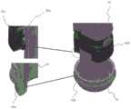
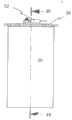
图1是低温真空烹饪器具的侧视截面示意图;1 is a schematic side cross-sectional view of a low-temperature vacuum cooking appliance;
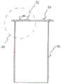
图2是图1的器具的外管道的示意性等距视图;Figure 2 is a schematic isometric view of the outer conduit of the appliance of Figure 1;
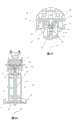
图3是图2的外管道的示意性部件分解等距视图;Figure 3 is a schematic exploded isometric view of the outer conduit of Figure 2;
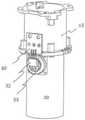
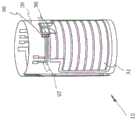
图4是图1的器具的外壳体的示意性底部等距视图,其上安装有开关;Figure 4 is a schematic bottom isometric view of the outer housing of the appliance of Figure 1 with a switch mounted thereon;
图5是图1的器具的一部分的示意性平面图;Figure 5 is a schematic plan view of a portion of the appliance of Figure 1;
图6是沿线6-6剖开的图5所示器具的示意性剖视侧视图;Figure 6 is a schematic cross-sectional side view of the appliance of Figure 5 taken along line 6-6;
图7是如图6所示的器具的部分7的示意性放大图;Fig. 7 is a schematic enlarged view of
图8是沿图6的线8-8剖开的器具的示意性剖视平面图;Figure 8 is a schematic cross-sectional plan view of the appliance taken along line 8-8 of Figure 6;
图9是图1的器具的开关和外壳体的一部分的示意性部件分解等距视图;9 is a schematic exploded isometric view of a portion of the switch and outer housing of the appliance of FIG. 1;
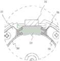
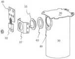
图10是如图9所示的器具的开关和外壳体的改型的示意性部件分解等距视图;图11是图1的低温真空烹饪器具的一部分的替代结构的示意性部件分解等距视图;Fig. 10 is a schematic exploded isometric view of a modification of the switch and outer casing of the appliance shown in Fig. 9; Fig. 11 is a schematic exploded isometric view of an alternate structure of a portion of the low temperature sous vide appliance of Fig. 1 ;
图12是图11所示的低温真空烹饪器具部分的示意性侧视图;Figure 12 is a schematic side view of the portion of the low temperature vacuum cooking appliance shown in Figure 11;
图13是沿线13-13剖开的图12的低温真空烹饪器具的示意性剖视平面图;Figure 13 is a schematic cross-sectional plan view of the low temperature sous vide cooking appliance of Figure 12 taken along line 13-13;
图14是沿线14-14剖开的图12的低温真空烹饪器具的示意性剖视侧视图;14 is a schematic cross-sectional side view of the low temperature sous vide cooking appliance of FIG. 12 taken along line 14-14;
图15是图13中确认的部分15的示意性放大图;Figure 15 is a schematic enlarged view of the
图16是图14中确认的部分16的示意性放大图;Figure 16 is a schematic enlarged view of the
图16A和16B是图1的低温真空烹饪器具的一部分的改型的示意性等距视图;16A and 16B are schematic isometric views of a modification of a portion of the low temperature sous vide appliance of FIG. 1;
图16C是图16A和图16B中所示的低温真空烹饪器具部分的示意性侧视图;图16D和图16E是图1所示的低温真空烹饪器具部分的改型的示意性剖面侧视图;Figure 16C is a schematic side view of the low temperature sous vide appliance portion shown in Figures 16A and 16B; Figures 16D and 16E are schematic cross-sectional side views of a modification of the low temperature sous vide appliance portion shown in Figure 1;
图16F是图16D和16E所示的低温真空烹饪器具部分的区域B的放大图;Fig. 16F is an enlarged view of region B of the low temperature sous vide appliance portion shown in Figs. 16D and 16E;
图16G是图16D和图16C中所示的低温真空烹饪器具部分的等距示意图;Figure 16G is a schematic isometric view of the portion of the low temperature sous vide appliance shown in Figures 16D and 16C;
图17是图1的低温真空烹饪器具的一部分的改型的示意性等距视图;Figure 17 is a schematic isometric view of a modification of a portion of the low temperature sous vide appliance of Figure 1;
图18是图17的低温真空烹饪器具部分的示意性部件分解等距视图;Figure 18 is a schematic exploded isometric view of the low temperature sous vide appliance portion of Figure 17;
图19是图1的低温真空烹饪器具的进一步改进部分的示意性侧视图;Figure 19 is a schematic side view of a further improved portion of the low temperature sous vide cooking appliance of Figure 1;
图20是沿线20-20剖开的图19的低温真空烹饪器具的示意性剖视侧视图;20 is a schematic cross-sectional side view of the low temperature sous vide cooking appliance of FIG. 19 taken along line 20-20;
图21是沿线21-21剖开的图19所示的低温真空烹饪器具的示意性剖视平面图;21 is a schematic cross-sectional plan view of the low temperature sous vide cooking appliance shown in FIG. 19 taken along line 21-21;
图22是图20中确认的部分22的示意性放大图;Figure 22 is a schematic enlarged view of the
图23是图21中确认的部分23的示意性放大图;Figure 23 is a schematic enlarged view of the
图24是图1的低温真空烹饪器具的一部分的替代结构的示意性等距视图;Fig. 24 is a schematic isometric view of an alternate structure for a portion of the low temperature sous vide appliance of Fig. 1;
图25是图24的低温真空烹饪器具部分的示意性部件分解等距视图;Figure 25 is a schematic exploded isometric view of the low temperature sous vide appliance portion of Figure 24;
图26是图24的低温真空烹饪器具部分的示意性侧视图;Figure 26 is a schematic side view of the portion of the low temperature sous vide appliance of Figure 24;
图27是沿线27-27剖开的图26所示的低温真空烹饪器具的示意性剖视侧视图;27 is a schematic cross-sectional side view of the low temperature sous vide cooking appliance shown in FIG. 26 taken along line 27-27;
图28是沿线28-28剖开的图26所示的低温真空烹饪器具的示意性平面图;Figure 28 is a schematic plan view of the low temperature sous vide cooking appliance shown in Figure 26, taken along line 28-28;
图29是图28中确认的部分的示意性放大图;Figure 29 is a schematic enlarged view of the portion identified in Figure 28;
图30是图27中确认的部分30的示意性放大图;Figure 30 is a schematic enlarged view of the
图31是图1的低温真空烹饪器具的一部分的替代结构的示意性等距视图;Figure 31 is a schematic isometric view of an alternate structure for a portion of the low temperature sous vide appliance of Figure 1;
图32是图31的低温真空烹饪器具部分的示意性部件分解等距视图;Figure 32 is a schematic exploded isometric view of the low temperature sous vide appliance portion of Figure 31;
图33是图31的低温真空烹饪器具部分的示意性侧视图;Figure 33 is a schematic side view of the portion of the low temperature sous vide appliance of Figure 31;
图34是沿线34-34剖开的图33所示的低温真空烹饪器具的示意性剖视侧视图;Figure 34 is a schematic cross-sectional side view of the low temperature sous vide cooking appliance shown in Figure 33 taken along line 34-34;
图35是沿线35-35剖开的图33所示的低温真空烹饪器具的示意性平面图;Figure 35 is a schematic plan view of the low temperature sous vide cooking appliance shown in Figure 33 taken along line 35-35;
图36是图34中确认的部分36的示意性放大图;Figure 36 is a schematic enlarged view of the
图37是图35中确认的部分37的示意性放大图;Figure 37 is a schematic enlarged view of the
图38是图1的低温真空烹饪器具的一部分的替代结构的示意性等距视图;Figure 38 is a schematic isometric view of an alternate structure for a portion of the low temperature sous vide appliance of Figure 1;
图39是图38的低温真空烹饪器具部分的示意性部件分解等距视图;Figure 39 is a schematic exploded isometric view of the low temperature sous vide appliance portion of Figure 38;
图40是图38的低温真空烹饪器具部分的示意性侧视图;Figure 40 is a schematic side view of the portion of the low temperature sous vide appliance of Figure 38;
图41是沿线41-41剖开的图40所示的低温真空烹饪器具的示意性平面图;图42是沿线42-42剖开的图40所示的低温真空烹饪器具的示意性剖视侧视图;Figure 41 is a schematic plan view of the low temperature sous vide appliance shown in Figure 40 taken along line 41-41; Figure 42 is a schematic cross-sectional side view of the low temperature sous vide appliance shown in Figure 40 taken along line 42-42 ;
图43是图42中确认的部分43的示意性放大图;Figure 43 is a schematic enlarged view of the
图44是图1的低温真空烹饪器具的一部分的替代结构的示意性等距视图;Fig. 44 is a schematic isometric view of an alternate structure for a portion of the low temperature sous vide appliance of Fig. 1;
图45是图44的低温真空烹饪器具部分的示意性部件分解等距视图;Figure 45 is a schematic exploded isometric view of the low temperature sous vide appliance portion of Figure 44;
图46是图44的低温真空烹饪器具部分的示意性俯视平面图;Figure 46 is a schematic top plan view of the low temperature sous vide appliance portion of Figure 44;
图47是图44的低温真空烹饪器具部分的示意性侧视图;Figure 47 is a schematic side view of the portion of the low temperature sous vide appliance of Figure 44;
图48是沿线48-48剖开的图47所示的低温真空烹饪器具的示意性剖视侧视图;Figure 48 is a schematic cross-sectional side view of the low temperature sous vide cooking appliance shown in Figure 47 taken along line 48-48;
图49是图48中确认的部分49的示意性放大图;Figure 49 is a schematic enlarged view of the
图50是图1的低温真空烹饪器具的一部分的替代结构的示意性等距视图;Fig. 50 is a schematic isometric view of an alternate structure of a portion of the low temperature sous vide appliance of Fig. 1;
图51是图50的低温真空烹饪器具部分的示意性部件分解等距视图;Figure 51 is a schematic exploded isometric view of the low temperature sous vide appliance portion of Figure 50;
图52是图50的低温真空烹饪器具部分的示意性剖视侧视图;Figure 52 is a schematic cross-sectional side view of the portion of the low temperature sous vide appliance of Figure 50;
图53是图51中确认的图52的部分的示意性放大图;Figure 53 is a schematic enlarged view of the portion of Figure 52 identified in Figure 51;
图54是与图1的设备一起使用的替代加热元件的示意性零件剖视侧视图;Figure 54 is a schematic part cross-sectional side view of an alternative heating element for use with the apparatus of Figure 1;
图55是图54所示设备的示意性等距视图;Figure 55 is a schematic isometric view of the apparatus shown in Figure 54;
图56是图1的低温真空烹饪器具的一部分的替代结构的示意性截面侧视图;Figure 56 is a schematic cross-sectional side view of an alternate structure for a portion of the low temperature sous vide appliance of Figure 1;
图57是图56的器具的一部分的示意性放大剖面侧视图;Figure 57 is a schematic enlarged cross-sectional side view of a portion of the appliance of Figure 56;
图58是可用于图1的器具中的替代加热元件的示意性等距视图;和Figure 58 is a schematic isometric view of an alternative heating element that may be used in the appliance of Figure 1; and
图59是图58的加热元件的示意性等距视图。FIG. 59 is a schematic isometric view of the heating element of FIG. 58 .
具体实施方式Detailed ways
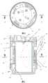
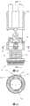
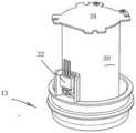
在图1至图10的附图中,示意性地示出了低温真空烹饪器具10。器具10具有外壳体11,外壳体11中安装有外管道12。外管道12具有纵向相对的端部13和14。固定在端部14上的是电动机安装件15。电动机16位于外壳体中。In the drawings of Figures 1 to 10, a low temperature sous vide cooking
电动机16接收电力并使其旋转。电动机16包括绕轴线89旋转以提供旋转磁场的多个磁体83。电动机16被固定到电动机壳体15并且位于横向壁39的一侧,以便不暴露于穿过器具10的液体。The
叶轮组件18由轴承组件支撑在固定轴86上。组件18包括支撑在轴86上的管状驱动轴85。叶轮组件18包括多个磁体84,其通过上述旋转磁场而绕轴线89旋转。这进而导致叶轮组件18绕轴线89旋转。The
叶轮组件18包括固定至轴85的内管道19,以使管道19与轴85一起旋转。由安装件87提供的叶轮叶片17固定到内管道19的末端,邻近端部13。叶轮组件18还包括固定至轴85的叶片88,并将管道19固定至轴85。The
内管道19位于外管道12的内部,内管道具有相对的第一端和第二端20和21。第一端13邻近第一端20,而第二端14邻近第二端21。Inside the
内管道19位于外管道12的内部,使得它们之间存在间隙,从而提供了外导管22。内管道19提供内导管23,管道22通过通道24连接到邻近端部13和20的导管23。管道18用作叶片88的叶轮分隔壁。The
外导管22、内导管23和通道24提供液体流动路径26,该液体流动路径从由内导管23在其端部13处提供的低温真空烹饪器具10的入口27延伸至低温真空烹饪器具10的出口28,该出口在端部13处由外导管22提供。将理解,低温真空烹饪器具10的入口27和出口28均位于端部13和20附近,即在同一纵向端部。因此,液体流动路径26的起点和终点与端部13和20相邻,即在同一纵向端部。将理解,在相同的纵向端部处提供液体流动路径26的起点和终点允许更一致或更均匀的水温进入和离开低温真空烹饪器具10。这种布置还可以允许将低温真空烹饪器具10放置在较低水平的水槽中。
在上述叶轮组件18的操作中,叶轮组件18的旋转使液体沿着路径26从内管道19的端部20处的入口27流到外管道12的端部13处的出口28。最初,叶轮叶片88朝着端部21推动液体,液体从端部14流动到叶片17,该叶片将液体推出出口28。在其他实施例(未示出)中,将理解,叶轮组件18可以被操作以使液体流动路径26的方向反向,使得液体从出口28(在该实施例中是入口)流至入口27(在该实施例中是出口)。In operation of the
流动路径26通过壁39与电动机壳体15的内部隔开。The
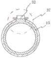
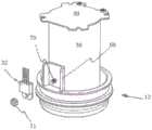
外管道12包括呈圆筒构造的管状部件30,并在其上固定有加热元件31。加热元件31被固定到构件30的外表面,电力被传递到元件31以加热管状构件30并且因此使液体通过。The
器具10具有用户界面81,电力通过电源线80输送到器具10,该用户界面连接至控制器82。控制器82将连接到界面81。
传递到加热元件31的电力通过开关32控制。优选地,开关32是三端双向交流开关,并且连接到控制器82。The power delivered to
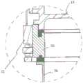
开关32通过螺纹紧固件34固定至散热器33。优选地,介电绝缘体35位于开关32和散热器33之间。
开关32位于端部13和14之间。在优选形式中,开关32位于端部13附近。因此,将理解,在将低温真空烹饪器具10放置在液槽中时,开关32可以由朝向液槽底部(即,靠近端部13)定位的冷却液进行传导冷却。将理解,盛有液体的容器的底部通常位于最冷的液体所在的位置,从而提供有效的散热器以将热量从开关32带走。
在上述实施例中,开关32通过传导冷却被水冷却,并且位于外壳体11和管道12之间的密封区域中,从而与加热元件31隔热。In the above-described embodiment, the
在该实施例中,壳体11具有弓形的内表面36,散热器33具有弓形的表面37,该弓形的表面37邻接表面36以提供热量从散热器33到壳体11的有效传递。In this embodiment,
螺母38固定到表面36,螺母38通过螺纹紧固件93接合以将散热器33固定到壳体11。螺纹紧固件93穿过散热器33中的孔并接合螺母38以将散热器33固定到壳体11。Secured to the
开关32固定到印刷电路板40上,导线41和导线42将开关32与加热元件31和未示出的控制机构连接。The
隔热构件43位于管状构件30与开关32之间,该隔热构件有效地使开关32与管状构件30隔热。An insulating
如图3中最佳可见,加热元件31不位于构件43所处的区域44中,再次至少有助于将开关32的温度保持在期望的限度内。As best seen in Figure 3, the
如图8和9最佳所示,构件43呈弧形,以匹配构件30的外表面45的弧形构造。As best shown in FIGS. 8 and 9 ,
散热器33有助于将开关32的温度保持在期望的限度内,同时还帮助从开关32吸取热量,并且将热量传导地输送到壳体11以从中消散。The
特别参考图10,介电绝缘体35安装在散热器33的凹槽46中,外壳体11设有一对穿过散热器33与螺母48啮合的螺纹突起47。轴47还穿过开关32并将导线42固定到开关32。10, the
优选地,在上述优选实施例中的散热器33是铝,优选地是挤压铝或铸铝,以实现最佳的传导性。Preferably, the
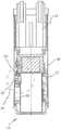
在图11至16中,示意性地示出了图1的低温真空烹饪器具的开关32的安装的替代构造。In Figures 11 to 16, an alternative configuration for the installation of the
在该结构中,管状构件30设置有孔49,开关32经由散热器35在该孔附近安装在管状构件30上。In this configuration, the
安装支架零件50和51将开关32与散热器35一起固定到管状构件30。紧固件53在零件50和51之间穿过,以将零件50和51围绕管状构件30夹紧。Mounting
密封件54将散热器35与管状构件30密封地连接,而垫片55帮助将散热器35安装在管状构件30上。
零件50具有孔53,开关32与线41和42一起穿过孔53。紧固件54将开关32固定到散热器35。
在上述替代构造中,散热器35以及因此开关32通过垫片55和密封件54与管状构件30牢固地绝缘。但是,由于散热器52暴露于沿外管道22通过的液体,因此散热器52被冷却。In the alternative construction described above, the
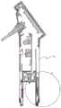
在图16A至16D中,示意性地示出了图1的低温真空烹饪器具的开关32和散热器33的安装的另一替代构造。In Figures 16A to 16D, another alternative configuration for the installation of the
在这种结构中,散热器33通过紧固件54a固定到壳体11。在优选形式中,紧固件54a是闩锁机构。如图16B最佳所示,紧固件54a包括分别在散热器33的第一端和第二端位于壳体11的内表面上的容纳部54b。散热器33包括突出部54c。在优选形式中,突出部54c从散热器33的中心突出。突出部54c与容纳部54b对准,并插入和安装在容纳部54b中。可弹性变形的弯曲的开环线元件54d插入到散热器33的第一端处的容纳部54b下方,并与散热器33的侧面上的朝内的开口槽对准。然后,操纵线元件54d的开口端以使其被捕获在散热器33的第二端处的容纳部54b下方。以此方式,线元件54d的变形沿着散热器33的任一侧施加恒定的力,以确保其强制地接触壳体11的内表面。这可以至少提供散热器33与壳体11之间的增强的接触以促进导热性。如上所述,开关32通过螺纹紧固件34固定至散热器33。In this structure, the
如图16C至16G最佳所示,在开关32和管状构件30之间提供了额外的绝热构件43a。绝热构件43a与管状构件30(并且因此与加热元件31)间隔开距离43b。绝热构件43a也与开关32间隔开距离43c。在优选形式中,距离43b和43c分别为大约1mm,并且优选地为大约0.9mm。应当理解,加热元件31、绝热构件43a和绝热构件43a与开关32之间的空间是气隙,其可以至少有助于向开关32提供绝热。在优选形式中,绝热构件43a由云母片形成。云母片优选具有约0.2mm的厚度43d。An additional insulating
如图16G中最佳地示出,绝热构件43a与上述绝热构件43的不同之处在于其较大的尺寸。这可以至少增加与加热元件31的热绝缘。在所示的实施例中,绝热构件43a被保持在凸缘43e下方的适当位置,该凸缘位于与电动机壳体15相邻的位置。As best shown in FIG. 16G, the insulating
在图17至23的结构中,用绝缘构件/密封件56代替密封件54和垫片55,该绝缘构件/密封件56被成形为容纳在孔49中以将散热器33安装在其中,但是,在横截面中,密封件56是“U”形,使得散热器33的外围容纳在其中。板57安装散热器33和管道30的密封件56,板57具有孔58,其与密封件56中的孔62一起用于将开关32固定到散热器33。在这一点上,散热器52具有带螺纹的凸起60,该凸起与螺母61接合以将开关32固定至散热器33。17 to 23,
在上述结构中,沿着外导管22流动的液体有助于冷却散热器35,从而有助于冷却开关32。In the above-described structure, the liquid flowing along the
在图24至图30的结构中,密封件56被替代绝缘体构件/密封件63替代,该绝缘体构件/密封件63的横截面为“L”构型。板57也具有替代构造。In the configuration of Figures 24-30,
在图31和32的实施例中,开关32安装在电动机壳体15上,而电动机壳体未安装在管状构件30上。电动机壳体15包括凸缘90,该凸缘固定到管状构件30的端部,以封闭管状构件30的端部。密封件91将凸缘90密封地连接到管状构件30的凸缘92。In the embodiment of FIGS. 31 and 32 , the
更具体地,该结构包括孔64,在孔64中其突出有散热器33。散热器33包括一对通道66,螺纹紧固件67穿过该通道与壳体15的部分68螺纹接合,从而固定到壳体上。More specifically, the structure includes a
开关32再次安装在散热器33上。The
印刷电路板40安装在壳体15上。The printed
在图33至37的实施例中,开关32再次安装在电动机壳体15上,而印刷电路板也安装在壳体15上。In the embodiment of FIGS. 33 to 37 , the
如图34最佳所示,电动机壳体15封闭了管状构件30的端部,但是,散热器33位于壳体15和管状构件30之间。通过封闭管状构件30的端部,壳体15使电动机16与液体流动路径26分离。As best seen in FIG. 34 , the
在图38和39的实施例中,固定(焊接)在管状构件30上的是安装体69,同时还在管状构件30上固定了螺纹突起70。安装体69具有“U”形构造,以便接收通过螺纹突起70穿过开关32中的孔以与螺母71接合而固定在适当位置的开关32。In the embodiment of FIGS. 38 and 39 , it is the mounting
如图40至43所示,开关32附接到安装件(散热器)78,该安装件至少部分地位于内管道30和壳体11之间。As shown in FIGS. 40 to 43 , the
在图44至图49的实施例中,开关32安装在横向壁上,使得沿路径26流动并与壁39相邻的液体有助于冷却开关32。然而,开关32通过壁39与流隔离。在图50至53的实施例中,开关32安装在管状构件30上,但是借助于绝缘构件44与之牢固地隔离。绝缘构件44具有孔72,该孔72使开关32沿路径26暴露于液体流,以帮助冷却开关32。开关32具有外螺纹,从而具有螺纹长度73,其螺纹地接合在绝缘构件44中。In the embodiment of FIGS. 44-49 , the
绝缘构件44通过与固定在管状构件35上的螺母76接合的螺纹紧固件75固定到管状构件35。The insulating
垫圈74被夹在构件44和构件30之间,以相对于构件30密封地安装构件44。如上所述,开关32安装在散热器33上。A
在上述优选实施例中,加热元件31被应用于内管道19。在替代构造中,如图55和56所示,加热元件31可以由位于外导管22中的加热线圈77代替。In the preferred embodiment described above, the
在图54和55的实施例中,开关32安装在壁39上。In the embodiment of FIGS. 54 and 55 , the
在上述优选实施例中,开关32与加热元件31位于其上的内管道19热隔离。In the preferred embodiment described above, the
在图56和57的实施例中,叶轮组件18包括与轴86接合的轴承组件90,使得叶轮组件18可以绕轴线89旋转。在这方面,应当理解,磁体83和84被吸引,使得组件18被保持抵靠轴86。然而,可以通过在远离轴86的方向上对其施加力来移除组件18。In the embodiment of FIGS. 56 and 57 , the
轴承组件90包括宝石轴承构件91,该宝石轴承构件具有凹腔92,轴86的弓形末端93容纳在该凹腔中。在这方面,末端93具有与空腔92匹配的凸表面。Bearing
优选地,宝石轴承构件91是红宝石轴承。Preferably, the
优选地,轴承91通过弹性轴承构件94固定到轴86的上端,该弹性轴承构件通常是弹性体。轴承元件94有助于吸收冲击,从而最小化施加到轴承元件91的冲击力。Preferably, the
在图58和59的实施例中,示出了外导管12的替代构造。In the embodiment of Figures 58 and 59, an alternative configuration of the
在该实施例中,加热元件31被施加到管状构件30,从而不被施加到管状构件30的可以将开关32固定到其上的区域95。以这种方式,抑制了由加热元件31产生的热量加热开关32。In this embodiment, the
另外,加热元件31具有与温度传感器98配合的纵向延伸部分96。感测温度的温度传感器98通过延伸到邻近突起96的位置的两个传导元件97发送信号,该信号指示突起96附近的温度。这种布置提供了关于温度传感器的更快的响应。作为替代方案,开关32可以邻近该区域安装在壳体11上,以再次至少抑制热量传递到开关32。Additionally, the
Claims (31)
Translated fromChinesePriority Applications (1)
| Application Number | Priority Date | Filing Date | Title |
|---|---|---|---|
| CN202311524854.5ACN117731152A (en) | 2018-03-29 | 2019-03-29 | Low-temperature vacuum cooking utensil |
Applications Claiming Priority (5)
| Application Number | Priority Date | Filing Date | Title |
|---|---|---|---|
| AU2018901051AAU2018901051A0 (en) | 2018-03-29 | A sous vide appliance | |
| AU2018901051 | 2018-03-29 | ||
| AU2018902304AAU2018902304A0 (en) | 2018-06-27 | A sous vide appliance | |
| AU2018902304 | 2018-06-27 | ||
| PCT/AU2019/050280WO2019183682A1 (en) | 2018-03-29 | 2019-03-29 | A sous vide appliance |
Related Child Applications (1)
| Application Number | Title | Priority Date | Filing Date |
|---|---|---|---|
| CN202311524854.5ADivisionCN117731152A (en) | 2018-03-29 | 2019-03-29 | Low-temperature vacuum cooking utensil |
Publications (2)
| Publication Number | Publication Date |
|---|---|
| CN112105279Atrue CN112105279A (en) | 2020-12-18 |
| CN112105279B CN112105279B (en) | 2023-12-01 |
Family
ID=68062459
Family Applications (4)
| Application Number | Title | Priority Date | Filing Date |
|---|---|---|---|
| CN201920414719.8UActiveCN210631056U (en) | 2018-03-29 | 2019-03-29 | Vacuum cooking appliance |
| CN201922170592.2UActiveCN212186115U (en) | 2018-03-29 | 2019-03-29 | Vacuum cooking appliance |
| CN201980030912.4AActiveCN112105279B (en) | 2018-03-29 | 2019-03-29 | Low-temperature vacuum cooking utensil |
| CN202311524854.5APendingCN117731152A (en) | 2018-03-29 | 2019-03-29 | Low-temperature vacuum cooking utensil |
Family Applications Before (2)
| Application Number | Title | Priority Date | Filing Date |
|---|---|---|---|
| CN201920414719.8UActiveCN210631056U (en) | 2018-03-29 | 2019-03-29 | Vacuum cooking appliance |
| CN201922170592.2UActiveCN212186115U (en) | 2018-03-29 | 2019-03-29 | Vacuum cooking appliance |
Family Applications After (1)
| Application Number | Title | Priority Date | Filing Date |
|---|---|---|---|
| CN202311524854.5APendingCN117731152A (en) | 2018-03-29 | 2019-03-29 | Low-temperature vacuum cooking utensil |
Country Status (6)
| Country | Link |
|---|---|
| US (2) | US12102253B2 (en) |
| EP (1) | EP3773088A4 (en) |
| CN (4) | CN210631056U (en) |
| AU (4) | AU2019240769B2 (en) |
| DE (1) | DE202019005644U1 (en) |
| WO (1) | WO2019183682A1 (en) |
Cited By (1)
| Publication number | Priority date | Publication date | Assignee | Title |
|---|---|---|---|---|
| WO2024108353A1 (en)* | 2022-11-21 | 2024-05-30 | 深圳市虎一科技有限公司 | Water tank connecting mechanism and water treatment device |
Families Citing this family (4)
| Publication number | Priority date | Publication date | Assignee | Title |
|---|---|---|---|---|
| EP4406459A3 (en)* | 2017-09-06 | 2024-11-06 | Breville Pty Limited | Sous vide device |
| US11375843B2 (en) | 2019-04-12 | 2022-07-05 | Anova Applied Electronics, Inc. | Sous vide cooker |
| EP4176692A4 (en)* | 2020-07-01 | 2024-11-27 | Breville Pty Limited | THERMAL IMMERSION CIRCULATOR DEVICE |
| USD1054246S1 (en)* | 2022-10-10 | 2024-12-17 | Shenzhen Typhur Technology Co., Ltd | Heating equipment for cooking appliance |
Citations (5)
| Publication number | Priority date | Publication date | Assignee | Title |
|---|---|---|---|---|
| US20080179311A1 (en)* | 2007-01-25 | 2008-07-31 | Fuat Koro | Infant feeding system |
| US20130220143A1 (en)* | 2012-02-29 | 2013-08-29 | Nomiku Inc. | Apparatus and system for low-temperature cooking |
| CN106133326A (en)* | 2013-11-28 | 2016-11-16 | 艾希蒂有限公司 | For LNG, lighter hydrocarbons and other non-conductive and low temperature submersible pumps of non-corrosive fluids |
| WO2017066692A1 (en)* | 2015-10-16 | 2017-04-20 | ChefSteps, Inc. | Thermal immersion circulator |
| CN106859286A (en)* | 2015-12-14 | 2017-06-20 | 北京奈思膳品科技有限公司 | A kind of low temperature cooking machine and low temperature cooking methods |
Family Cites Families (3)
| Publication number | Priority date | Publication date | Assignee | Title |
|---|---|---|---|---|
| ITPN20020082A1 (en)* | 2002-10-10 | 2004-04-11 | Irca Spa | PERFECTED FLUID HEATER TUBE. |
| US9687104B2 (en)* | 2013-02-14 | 2017-06-27 | Anova Applied Electronics, Inc. | Circulator cooker |
| US20160192801A1 (en)* | 2015-01-02 | 2016-07-07 | Jeff Wu | Circulator cooker |
- 2019
- 2019-03-29WOPCT/AU2019/050280patent/WO2019183682A1/ennot_activeCeased
- 2019-03-29USUS17/042,906patent/US12102253B2/enactiveActive
- 2019-03-29AUAU2019240769Apatent/AU2019240769B2/enactiveActive
- 2019-03-29CNCN201920414719.8Upatent/CN210631056U/enactiveActive
- 2019-03-29DEDE202019005644.0Upatent/DE202019005644U1/enactiveActive
- 2019-03-29CNCN201922170592.2Upatent/CN212186115U/enactiveActive
- 2019-03-29CNCN201980030912.4Apatent/CN112105279B/enactiveActive
- 2019-03-29CNCN202311524854.5Apatent/CN117731152A/enactivePending
- 2019-03-29EPEP19776870.8Apatent/EP3773088A4/enactivePending
- 2021
- 2021-03-19AUAU2021101423Apatent/AU2021101423B4/enactiveActive
- 2022
- 2022-08-18AUAU2022218557Apatent/AU2022218557B2/enactiveActive
- 2023
- 2023-07-20AUAU2023206194Apatent/AU2023206194A1/enactivePending
- 2024
- 2024-09-30USUS18/901,056patent/US20250017409A1/enactivePending
Patent Citations (5)
| Publication number | Priority date | Publication date | Assignee | Title |
|---|---|---|---|---|
| US20080179311A1 (en)* | 2007-01-25 | 2008-07-31 | Fuat Koro | Infant feeding system |
| US20130220143A1 (en)* | 2012-02-29 | 2013-08-29 | Nomiku Inc. | Apparatus and system for low-temperature cooking |
| CN106133326A (en)* | 2013-11-28 | 2016-11-16 | 艾希蒂有限公司 | For LNG, lighter hydrocarbons and other non-conductive and low temperature submersible pumps of non-corrosive fluids |
| WO2017066692A1 (en)* | 2015-10-16 | 2017-04-20 | ChefSteps, Inc. | Thermal immersion circulator |
| CN106859286A (en)* | 2015-12-14 | 2017-06-20 | 北京奈思膳品科技有限公司 | A kind of low temperature cooking machine and low temperature cooking methods |
Cited By (1)
| Publication number | Priority date | Publication date | Assignee | Title |
|---|---|---|---|---|
| WO2024108353A1 (en)* | 2022-11-21 | 2024-05-30 | 深圳市虎一科技有限公司 | Water tank connecting mechanism and water treatment device |
Also Published As
| Publication number | Publication date |
|---|---|
| AU2021101423A4 (en) | 2021-05-13 |
| CN112105279B (en) | 2023-12-01 |
| CN212186115U (en) | 2020-12-22 |
| US20210052102A1 (en) | 2021-02-25 |
| CN117731152A (en) | 2024-03-22 |
| DE202019005644U1 (en) | 2021-11-15 |
| EP3773088A4 (en) | 2022-01-05 |
| EP3773088A1 (en) | 2021-02-17 |
| US20250017409A1 (en) | 2025-01-16 |
| RU2020135484A (en) | 2022-04-29 |
| AU2022218557B2 (en) | 2023-04-06 |
| AU2022218557A1 (en) | 2022-09-15 |
| WO2019183682A1 (en) | 2019-10-03 |
| CN210631056U (en) | 2020-05-29 |
| AU2021101423B4 (en) | 2023-06-01 |
| AU2019240769B2 (en) | 2023-04-20 |
| AU2019240769A1 (en) | 2020-11-19 |
| AU2023206194A1 (en) | 2023-08-10 |
| US12102253B2 (en) | 2024-10-01 |
Similar Documents
| Publication | Publication Date | Title |
|---|---|---|
| CN112105279B (en) | Low-temperature vacuum cooking utensil | |
| CN111802898B (en) | Vacuum low-temperature cooking device | |
| CN113923806B (en) | Thermal Immersion Circulator | |
| US20070228032A1 (en) | Thick-Film Fluid Heater and Continuous Heating Device | |
| CN115956396A (en) | Hot soak device | |
| RU2788717C2 (en) | Device for low-temperature cooking | |
| KR20170099685A (en) | Module for heating and cooling cup using Peltier thermoelectric element | |
| CN213238012U (en) | Refrigeration and heating device and household appliance | |
| KR20090009524U (en) | Multifunction Microwave | |
| CN211511534U (en) | Electromagnetic heating assembly for wall breaking machine and wall breaking machine with electromagnetic heating assembly | |
| CN211152226U (en) | Electromagnetic heating assembly for wall breaking machine and wall breaking machine with same | |
| KR20080078761A (en) | Induction burner | |
| JP7429518B2 (en) | liquid heating device | |
| CN210197366U (en) | Cooking device and heating system | |
| JP6887395B2 (en) | Induction heating cooker | |
| EP1766297B1 (en) | Improvement in a fluid heating means | |
| JP2005037004A (en) | Cooker | |
| HK1105145B (en) | Improvement in a fluid heating means |
Legal Events
| Date | Code | Title | Description |
|---|---|---|---|
| PB01 | Publication | ||
| PB01 | Publication | ||
| SE01 | Entry into force of request for substantive examination | ||
| SE01 | Entry into force of request for substantive examination | ||
| CB03 | Change of inventor or designer information | Inventor after:B Fawkes Lee Inventor after:G. Apston Inventor after:L.Meng Inventor after:M, S, Rowe, Sean Inventor after:V. Ross Inventor after:W.Shen Inventor before:B Fawkes Lee Inventor before:G. Apston Inventor before:A.Meng Inventor before:M, S, Rowe, Sean Inventor before:V. Ross Inventor before:W.Shen | |
| CB03 | Change of inventor or designer information | ||
| GR01 | Patent grant | ||
| GR01 | Patent grant |