CN112104995B - A mushroom growth environment monitoring device and system capable of remote wake-up - Google Patents
A mushroom growth environment monitoring device and system capable of remote wake-upDownload PDFInfo
- Publication number
- CN112104995B CN112104995BCN202010775439.7ACN202010775439ACN112104995BCN 112104995 BCN112104995 BCN 112104995BCN 202010775439 ACN202010775439 ACN 202010775439ACN 112104995 BCN112104995 BCN 112104995B
- Authority
- CN
- China
- Prior art keywords
- radio frequency
- wake
- module
- microcontroller
- mobile robot
- Prior art date
- Legal status (The legal status is an assumption and is not a legal conclusion. Google has not performed a legal analysis and makes no representation as to the accuracy of the status listed.)
- Active
Links
- 235000001674Agaricus brunnescensNutrition0.000titleclaimsabstractdescription20
- 238000012806monitoring deviceMethods0.000titleclaimsdescription11
- 238000012544monitoring processMethods0.000claimsabstractdescription29
- 238000004891communicationMethods0.000claimsdescription13
- 230000007613environmental effectEffects0.000claimsdescription11
- 230000002093peripheral effectEffects0.000claimsdescription4
- 230000009471actionEffects0.000claimsdescription2
- 230000002457bidirectional effectEffects0.000claimsdescription2
- 230000003993interactionEffects0.000abstractdescription2
- 230000002035prolonged effectEffects0.000abstract1
- 238000010586diagramMethods0.000description12
- 230000006870functionEffects0.000description9
- 230000005540biological transmissionEffects0.000description7
- 238000000034methodMethods0.000description5
- 238000001514detection methodMethods0.000description3
- 238000007726management methodMethods0.000description3
- 230000008569processEffects0.000description3
- 238000012545processingMethods0.000description3
- 238000005265energy consumptionMethods0.000description2
- 230000007774longtermEffects0.000description2
- 235000015097nutrientsNutrition0.000description2
- 241000894006BacteriaSpecies0.000description1
- 230000008901benefitEffects0.000description1
- 238000012790confirmationMethods0.000description1
- 238000005260corrosionMethods0.000description1
- 238000013500data storageMethods0.000description1
- 238000013461designMethods0.000description1
- 238000003745diagnosisMethods0.000description1
- 230000000694effectsEffects0.000description1
- 239000000463materialSubstances0.000description1
- 230000007246mechanismEffects0.000description1
- 230000006855networkingEffects0.000description1
- 230000000630rising effectEffects0.000description1
- 230000008054signal transmissionEffects0.000description1
- XLYOFNOQVPJJNP-UHFFFAOYSA-NwaterSubstancesOXLYOFNOQVPJJNP-UHFFFAOYSA-N0.000description1
Images


Classifications
- H—ELECTRICITY
- H04—ELECTRIC COMMUNICATION TECHNIQUE
- H04W—WIRELESS COMMUNICATION NETWORKS
- H04W4/00—Services specially adapted for wireless communication networks; Facilities therefor
- H04W4/30—Services specially adapted for particular environments, situations or purposes
- H04W4/38—Services specially adapted for particular environments, situations or purposes for collecting sensor information
- G—PHYSICS
- G08—SIGNALLING
- G08C—TRANSMISSION SYSTEMS FOR MEASURED VALUES, CONTROL OR SIMILAR SIGNALS
- G08C17/00—Arrangements for transmitting signals characterised by the use of a wireless electrical link
- G08C17/02—Arrangements for transmitting signals characterised by the use of a wireless electrical link using a radio link
- H—ELECTRICITY
- H04—ELECTRIC COMMUNICATION TECHNIQUE
- H04L—TRANSMISSION OF DIGITAL INFORMATION, e.g. TELEGRAPHIC COMMUNICATION
- H04L67/00—Network arrangements or protocols for supporting network services or applications
- H04L67/01—Protocols
- H04L67/12—Protocols specially adapted for proprietary or special-purpose networking environments, e.g. medical networks, sensor networks, networks in vehicles or remote metering networks
- H—ELECTRICITY
- H04—ELECTRIC COMMUNICATION TECHNIQUE
- H04Q—SELECTING
- H04Q9/00—Arrangements in telecontrol or telemetry systems for selectively calling a substation from a main station, in which substation desired apparatus is selected for applying a control signal thereto or for obtaining measured values therefrom
- H—ELECTRICITY
- H04—ELECTRIC COMMUNICATION TECHNIQUE
- H04W—WIRELESS COMMUNICATION NETWORKS
- H04W4/00—Services specially adapted for wireless communication networks; Facilities therefor
- H04W4/70—Services for machine-to-machine communication [M2M] or machine type communication [MTC]
- H—ELECTRICITY
- H04—ELECTRIC COMMUNICATION TECHNIQUE
- H04W—WIRELESS COMMUNICATION NETWORKS
- H04W52/00—Power management, e.g. Transmission Power Control [TPC] or power classes
- H04W52/02—Power saving arrangements
- H04W52/0209—Power saving arrangements in terminal devices
- H—ELECTRICITY
- H04—ELECTRIC COMMUNICATION TECHNIQUE
- H04Q—SELECTING
- H04Q2209/00—Arrangements in telecontrol or telemetry systems
- H04Q2209/40—Arrangements in telecontrol or telemetry systems using a wireless architecture
- H—ELECTRICITY
- H04—ELECTRIC COMMUNICATION TECHNIQUE
- H04Q—SELECTING
- H04Q2209/00—Arrangements in telecontrol or telemetry systems
- H04Q2209/80—Arrangements in the sub-station, i.e. sensing device
- H04Q2209/88—Providing power supply at the sub-station
- H04Q2209/883—Providing power supply at the sub-station where the sensing device enters an active or inactive mode
- Y—GENERAL TAGGING OF NEW TECHNOLOGICAL DEVELOPMENTS; GENERAL TAGGING OF CROSS-SECTIONAL TECHNOLOGIES SPANNING OVER SEVERAL SECTIONS OF THE IPC; TECHNICAL SUBJECTS COVERED BY FORMER USPC CROSS-REFERENCE ART COLLECTIONS [XRACs] AND DIGESTS
- Y02—TECHNOLOGIES OR APPLICATIONS FOR MITIGATION OR ADAPTATION AGAINST CLIMATE CHANGE
- Y02D—CLIMATE CHANGE MITIGATION TECHNOLOGIES IN INFORMATION AND COMMUNICATION TECHNOLOGIES [ICT], I.E. INFORMATION AND COMMUNICATION TECHNOLOGIES AIMING AT THE REDUCTION OF THEIR OWN ENERGY USE
- Y02D30/00—Reducing energy consumption in communication networks
- Y02D30/70—Reducing energy consumption in communication networks in wireless communication networks
Landscapes
- Engineering & Computer Science (AREA)
- Computer Networks & Wireless Communication (AREA)
- Signal Processing (AREA)
- Physics & Mathematics (AREA)
- General Physics & Mathematics (AREA)
- Health & Medical Sciences (AREA)
- Computing Systems (AREA)
- General Health & Medical Sciences (AREA)
- Medical Informatics (AREA)
- Selective Calling Equipment (AREA)
Abstract
Description
Translated fromChinese技术领域technical field
本发明涉及智慧农业、物联网、移动机器人领域,尤其涉及能够远程唤醒的菌菇生长环境监测设备和系统。The present invention relates to the fields of smart agriculture, the Internet of Things, and mobile robots, and in particular to a mushroom growth environment monitoring device and system capable of remote wake-up.
背景技术Background technique
菌菇的培育对生长环境的要求非常严苛,菌菇生长的养分、温度、水分、空气、光照、pH值等的变化都必须保持在一个比较有限的范围内,才能培育出品质优良的菌菇。菌菇培育的这一特点导致对于菌菇生长环境参数的监控必须经常处于工作状态,但长时间的工作又会导致监控终端设备的功耗增加。菌菇生长的环境中,需要布设大量的监测终端,采用有线供电的方式不符合现场的实际情况。因此只能采用电池供电的方式,为在有限的电池容量下使得检测设备的寿命达到最大化,常用的解决方案是给标签设定一个定时唤醒机制。但唤醒的时间间隔不能过长,否则不能及时响应读头,这样不论读头有无读取信息需求,设备都在发送数据、消耗能量。另外定时唤醒需要时钟电路工作,意味着设备不能进入彻底休眠状态。因此定时唤醒不能达到最佳的节能效果。The cultivation of mushrooms has very strict requirements on the growth environment. The changes in nutrients, temperature, water, air, light, pH value, etc. for the growth of mushrooms must be kept within a relatively limited range in order to cultivate high-quality bacteria. mushroom. This characteristic of mushroom cultivation leads to the monitoring of the environmental parameters of mushroom growth must always be in the working state, but working for a long time will lead to an increase in the power consumption of the monitoring terminal equipment. In the environment where mushrooms grow, a large number of monitoring terminals need to be deployed, and the way of using wired power supply is not in line with the actual situation on site. Therefore, it can only be powered by batteries. In order to maximize the life of the detection equipment under the limited battery capacity, a common solution is to set a timing wake-up mechanism for the tag. However, the wake-up time interval should not be too long, otherwise the reading head cannot be responded in time, so the device is sending data and consuming energy no matter whether the reading head needs to read information or not. In addition, timing wake-up requires the clock circuit to work, which means that the device cannot enter a complete sleep state. Therefore, timing wake-up cannot achieve the best energy-saving effect.
发明内容Contents of the invention
本发明针对长时间在线监测菌菇培育过程中的生长参数,环境数据的问题,本发明提出了一种基于移动机器人远程唤醒的菌菇生长环境监测设备。利用移动机器人做远程唤醒,让检测设备只在需要的时间工作来采集数据,其他时间则保持关机状态,从而实现了菌菇培育应用环境的检测设备低功耗的要求,保障了设备的长时间运行而无需供电。Aiming at the problem of long-term online monitoring of growth parameters and environmental data in the mushroom cultivation process, the present invention proposes a mushroom growth environment monitoring device based on remote wake-up of a mobile robot. Use the mobile robot to do remote wake-up, so that the detection equipment can only work at the required time to collect data, and keep the shutdown state at other times, thus realizing the low power consumption requirements of the detection equipment in the mushroom cultivation application environment, and ensuring the long-term use of the equipment Runs without power.
本发明的基于移动机器人远程唤醒的菌菇生长环境监测设备包括:微控制器、功能模块和射频唤醒模块,微控制器作连接到功能模块,微控制器接收来自射频唤醒模块的触发唤醒信号后,启动功能模块开始工作,与外部进行数据交互。The mushroom growth environment monitoring device based on the remote wake-up of the mobile robot of the present invention includes: a microcontroller, a function module and a radio frequency wake-up module, the microcontroller is connected to the function module, and after the microcontroller receives the trigger wake-up signal from the radio frequency wake-up module , start the function module to start working, and perform data interaction with the outside.
对应的,本发明还提出一种基于移动机器人远程唤醒的菌菇生长环境监测系统,包括:环境监测设备和移动机器人,Correspondingly, the present invention also proposes a mushroom growth environment monitoring system based on the remote wake-up of mobile robots, including: environmental monitoring equipment and mobile robots,
环境监测设备包括:微控制器、功能模块和射频唤醒模块,微控制器作连接到功能模块,微控制器接收来自射频唤醒模块的触发唤醒信号后,启动功能模块开始工作,与移动机器人进行数据交互;The environmental monitoring equipment includes: a microcontroller, a functional module and a radio frequency wake-up module. The microcontroller is connected to the functional module. After the microcontroller receives the trigger wake-up signal from the radio frequency wake-up module, the functional module starts to work and communicates with the mobile robot. interact;
移动机器人,其能够发射射频信号给所述射频唤醒模块,射频唤醒模块将所述射频信号转换为唤醒信号,以唤醒所述微控制器。The mobile robot can transmit a radio frequency signal to the radio frequency wake-up module, and the radio frequency wake-up module converts the radio frequency signal into a wake-up signal to wake up the microcontroller.
与现有技术相比,本发明的技术优势在于:Compared with prior art, the technical advantage of the present invention is:
1.内置射频唤醒模块,平时设备以处于几乎完全休眠的状态,当被唤醒后再恢复工作,大大延长了设备的使用时间。1. Built-in radio frequency wake-up module, usually the device is almost completely dormant, and resumes work after being awakened, which greatly prolongs the use time of the device.
2.与移动机器人配合,通过移动机器人载的射频发射模块作为唤醒信号,协调终端设备与移动机器人的工作时间,避免了无效的工作能耗。2. Cooperate with the mobile robot, use the radio frequency transmitting module carried by the mobile robot as a wake-up signal, coordinate the working time of the terminal equipment and the mobile robot, and avoid ineffective work energy consumption.
3.监测设备仅在移动机器人临近时进行唤醒后的数据传输,可以减少发射功率的消耗,延长使用寿命。3. The monitoring equipment only performs data transmission after wake-up when the mobile robot is approaching, which can reduce the consumption of transmission power and prolong the service life.
4.设备可支持长距离范围内的无线数据传输以及组网,特别适合边缘农村种植基地使用。4. The device can support wireless data transmission and networking within a long distance, especially suitable for marginal rural planting bases.
5.内置数据存储功能,可以在无网络的环境下进行工作,待下一次唤醒时再将数据上传移动机器人或数据中心,实现了数据的异步传输。5. With built-in data storage function, it can work in an environment without network, and then upload the data to the mobile robot or data center when it wakes up next time, realizing the asynchronous transmission of data.
附图说明Description of drawings
为了更容易理解本发明,将通过参照附图中示出的具体实施方式更详细地描述本发明。这些附图只描绘了本发明的典型实施方式,不应认为对本发明保护范围的限制。For easier understanding of the present invention, the present invention will be described in more detail by referring to specific embodiments shown in the accompanying drawings. These drawings only depict typical embodiments of the invention and should not be considered as limiting the scope of the invention.
图1为本发明的设备的应用场景的结构框图。FIG. 1 is a structural block diagram of an application scenario of a device of the present invention.
图2为监测设备终端硬件系统框图。Figure 2 is a block diagram of the monitoring equipment terminal hardware system.
图3为移动机器人载射频发射模块系统硬件框图。Figure 3 is a hardware block diagram of the radio frequency transmitting module system carried by the mobile robot.
图4为监测设备的一个实施方式的电路图。Figure 4 is a circuit diagram of one embodiment of a monitoring device.
图5为移动机器人的射频发射端的一个实施方式的电路图。Fig. 5 is a circuit diagram of an embodiment of a radio frequency transmitting end of a mobile robot.
图6为移动机器人的射频发射端的工作流程图。Fig. 6 is a working flow chart of the radio frequency transmitter of the mobile robot.
图7为监测设备的工作流程图。Fig. 7 is a working flow diagram of the monitoring equipment.
具体实施方式Detailed ways
下面参照附图描述本发明的实施方式,其中相同的部件用相同的附图标记表示。在不冲突的情况下,下述的实施例及实施例中的技术特征可以相互组合。Embodiments of the present invention are described below with reference to the drawings, in which like parts are denoted by like reference numerals. In the case of no conflict, the following embodiments and the technical features in the embodiments can be combined with each other.
图1显示了系统原理图,该系统中使用了本发明的监测设备。所述系统包括监测设备和移动机器人所载的读头端(即射频发射模块)。监测设备包括微控制器、射频唤醒模块、功能模块(实现其他功能)等。微控制器作为设备终端侧的控制核心,连接功能模块,接收来自射频唤醒模块的触发唤醒信号后,启动开始工作,与移动机器人进行数据交互。Figure 1 shows a schematic diagram of a system in which the monitoring device of the present invention is used. The system includes a monitoring device and a reading head end (that is, a radio frequency transmitting module) carried by a mobile robot. The monitoring equipment includes a microcontroller, a radio frequency wake-up module, a function module (to realize other functions), etc. As the control core of the device terminal side, the microcontroller is connected to the functional modules, and after receiving the trigger wake-up signal from the radio frequency wake-up module, it starts to work and interacts with the mobile robot for data.
移动机器人载有射频发射模块,射频发射模块连接到微控制器,该微控制器与控制器接口相连接。监控中心可以通过该控制器接口向微控制器发送指令,微控制器操作射频发射模块发出高功率射频信号,以远程唤醒远程监测终端设备,通知该终端设备将采集的环境数据发回移动机器人或者监控中心。The mobile robot is loaded with a radio frequency transmitting module, and the radio frequency transmitting module is connected to a microcontroller, and the microcontroller is connected with a controller interface. The monitoring center can send instructions to the microcontroller through the controller interface, and the microcontroller operates the radio frequency transmitting module to send a high-power radio frequency signal to remotely wake up the remote monitoring terminal equipment and notify the terminal equipment to send the collected environmental data back to the mobile robot or monitoring Center.
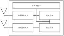
图2显示了监测设备的结构。本发明的监测设备包括微控制器、射频唤醒模块、无线通信模块、电源管理模块、内置电池、外围设备接口以及多个传感器。Figure 2 shows the structure of the monitoring equipment. The monitoring device of the present invention includes a microcontroller, a radio frequency wake-up module, a wireless communication module, a power management module, a built-in battery, a peripheral device interface and multiple sensors.
微控制器为监测设备的控制核心,与射频唤醒模块连接,接收射频唤醒模块的唤醒信号。微控制器负责整个监测设备的控制以及算法,兼有数据处理存储的功能,能够在没有网络传输的情况下保存一段时间的来自传感器的环境数据。The microcontroller is the control core of the monitoring equipment, connected with the radio frequency wake-up module, and receives the wake-up signal of the radio frequency wake-up module. The microcontroller is responsible for the control and algorithm of the entire monitoring equipment, and also has the function of data processing and storage, and can save the environmental data from the sensor for a period of time without network transmission.
射频唤醒接收模块可检测到有满足协议的15K~125KHz的射频信号,产生动作唤醒微控制器。射频唤醒模块通过射频线圈(天线)接收来自移动机器人载的射频发射端的射频信号,将其转换为唤醒信号,以唤醒微控制器。微控制器唤醒后,通过外围设备接口采集传感器数据,并通过无线通信通信模块发送给移动机器人或者监控中心。外围设备接口包括UART、USB、LAN、IO、SPI等不同的通信协议方式,不断轮询传感器的数据,并将数据传给微控制器进行处理。The radio frequency wake-up receiving module can detect a radio frequency signal of 15K-125KHz that meets the protocol, and generate an action to wake up the microcontroller. The radio frequency wake-up module receives the radio frequency signal from the radio frequency transmitter carried by the mobile robot through the radio frequency coil (antenna), and converts it into a wake-up signal to wake up the microcontroller. After the microcontroller wakes up, it collects sensor data through the peripheral device interface, and sends it to the mobile robot or the monitoring center through the wireless communication module. Peripheral device interfaces include UART, USB, LAN, IO, SPI and other different communication protocol methods, continuously poll the sensor data, and transmit the data to the microcontroller for processing.
电源管理模块连接内置电池,给监测设备的各个模块提供电能,并且支持不同能耗的工作模式,如工作,发射,空闲,休眠,断电等。The power management module is connected to the built-in battery to provide power to each module of the monitoring device, and supports different energy consumption working modes, such as working, transmitting, idle, sleeping, power off, etc.
传感器通过接口连接微控制器,根据不同的传感器类型采集菌菇生长的环境环境要素,如养分、温度、水分、空气、光照、pH值等。The sensor is connected to the microcontroller through the interface, and according to different sensor types, the environmental factors of mushroom growth, such as nutrients, temperature, moisture, air, light, pH value, etc. are collected.
无线通信模块,连接到微控制器,可以进行远距离通信,通信距离可达3~10~公里。The wireless communication module, connected to the microcontroller, can perform long-distance communication, and the communication distance can reach 3-10-kilometers.
终端设备的硬件电路被封装在由ABS或PC等防腐材料构成的壳体之中,保证内部电路的稳定运行。The hardware circuit of the terminal device is encapsulated in a housing made of anti-corrosion materials such as ABS or PC to ensure the stable operation of the internal circuit.
图3显示了移动机器人的读头端的结构框图。移动机器人包括微控制器,无线通信模块、射频发射模块、电源管理模块以及控制器接口,所述控制器接口用于连接外部设备。Figure 3 shows the structural block diagram of the reading head end of the mobile robot. The mobile robot includes a microcontroller, a wireless communication module, a radio frequency transmitting module, a power management module and a controller interface, and the controller interface is used for connecting external devices.
微控制器负责对无线通信模块、射频信号发射模块的控制及与通过接口上位机(移动机器人控制器)的通讯。无线通信模块负责与监测设备的数据通信。射频发射模块产生15k~125KHz的射频信号,以唤醒监测设备。The microcontroller is responsible for the control of the wireless communication module, the radio frequency signal transmission module and the communication with the upper computer (mobile robot controller) through the interface. The wireless communication module is responsible for the data communication with the monitoring equipment. The radio frequency transmitting module generates a radio frequency signal of 15k~125KHz to wake up the monitoring equipment.
射频发射模块通过一个“单线双向”接口(DIO pin),由微控制器控制,配合天线线圈发射15K~125KHz射频载波传送数据和能量。芯片的工作电压为8~24V。它内部包含了一个VCO(压控振荡器)给接口逻辑门电路和门驱动逻辑电路提供时钟。当天线半桥处于非激活状态时VCO工作在自振荡模式。当天线半桥处于激活状态时,VCO工作在谐振跟踪模式——通过检测天线LC电路自身谐振时的电流过零点产生VCO的时钟频率。芯片驱动天线线圈的峰值电流是可调的,峰值电流最大可以达到1.5A。可以根据实际需要调整外部电阻阻值使得天线发射不同功率。The RF transmitter module is controlled by a microcontroller through a "single-wire bidirectional" interface (DIO pin), and cooperates with the antenna coil to transmit 15K-125KHz RF carrier to transmit data and energy. The operating voltage of the chip is 8-24V. It contains a VCO (Voltage Controlled Oscillator) to provide clock for the interface logic gate circuit and gate drive logic circuit. When the antenna half-bridge is inactive, the VCO works in self-oscillation mode. When the antenna half-bridge is active, the VCO works in resonant tracking mode—the clock frequency of the VCO is generated by detecting the current zero-crossing point when the antenna LC circuit resonates itself. The peak current of the chip driving the antenna coil is adjustable, and the maximum peak current can reach 1.5A. The resistance value of the external resistor can be adjusted according to actual needs so that the antenna can emit different powers.
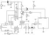
图4显示了监测设备的一个实施方式的电路图。该电路图的主要元件包括微控制器,低频唤醒接收器,单刀双掷模拟开关,低压稳压器等。微控制器负责配置其他元件的状态设置,与其他单元进行数据通讯,并进行数据。低频唤醒接收器通过射频通道接受低频唤醒信号,并将唤醒信号输出到其他元器件。模拟开关负责关断和接通电路。低压稳压器对电路供电进行调节,消除电路文波,保持电压稳定。Figure 4 shows a circuit diagram of one embodiment of the monitoring device. The main components of this circuit diagram include microcontroller, low frequency wake-up receiver, SPDT analog switch, low voltage regulator, etc. The microcontroller is responsible for configuring the state settings of other components, communicating data with other units, and processing data. The low-frequency wake-up receiver receives the low-frequency wake-up signal through the radio frequency channel, and outputs the wake-up signal to other components. An analog switch is responsible for turning off and turning on the circuit. The low-voltage regulator regulates the power supply of the circuit, eliminates the ripple of the circuit, and keeps the voltage stable.
图5显示了移动机器人的一个实施方式的电路图。该电路的主要元件包括低频信号发射器和微控制器。低频信号发射器通过一个“单线双向”接口由外部微控制器控制,并配合天线线圈发射低频载波传送数据和能量。它内部包含了一个压控振荡器给接口逻辑门电路和门驱动逻辑电路提供时钟。当天线半桥处于非激活状态时,压控振荡器工作在自振荡模式;当天线半桥处于激活状态时,压控振荡器工作在谐振跟踪模式。通过检测天线电路自身谐振时的电流过零点产生压控振荡器的时钟频率。芯片驱动天线线圈的峰值电流是可调的,可以根据实际需要调整外部电阻阻值使得天线发射不同功率。此外低频信号发射器还整合了电路诊断和自保护功能。如果发送的序列正常,它将在数据发送结束后给出一个负脉冲。在发送过程中,如果检测到有下面三种情况,则认为有错误:a)供电电压小于6.5V;b)谐振频率不在80kHz和150Khz之间;c)天线电流超出设定范围10%。一旦发生错误,它会在发送完后给出一个负脉冲。电路会在电压超过或芯片过热情况下,启动自保护。Figure 5 shows a circuit diagram of one embodiment of a mobile robot. The main components of this circuit include a low frequency signal transmitter and a microcontroller. The low-frequency signal transmitter is controlled by an external microcontroller through a "single-wire two-way" interface, and cooperates with the antenna coil to transmit low-frequency carrier waves to transmit data and energy. It contains a voltage-controlled oscillator to provide clock for the interface logic gate circuit and gate drive logic circuit. When the antenna half-bridge is inactive, the voltage-controlled oscillator works in self-oscillation mode; when the antenna half-bridge is active, the voltage-controlled oscillator works in resonance tracking mode. The clock frequency of the voltage controlled oscillator is generated by detecting the zero crossing of the current when the antenna circuit self-resonates. The peak current of the chip driving the antenna coil is adjustable, and the external resistance value can be adjusted according to actual needs to make the antenna emit different powers. In addition, the low-frequency signal transmitter also integrates circuit diagnosis and self-protection functions. If the sequence sent is normal, it will give a negative pulse after the end of data transmission. During the sending process, if the following three conditions are detected, it is considered to be an error: a) the power supply voltage is less than 6.5V; b) the resonance frequency is not between 80kHz and 150Khz; c) the antenna current exceeds the set range by 10%. In case of error, it will give a negative pulse after sending. The circuit will start self-protection when the voltage exceeds or the chip is overheated.
图6显示了移动机器人的射频发射端的工作流程图。移动机器人载射频发射端的微控制器上电后初始化,P1.7和P1.6设为推挽输出模式。P1.7在微控制器不工作时一直保持低电平。对应DIO为高电平。P2.7设为输入模式,用于捕获DIO反馈的确认信号。在数据发送完后延时大约15ms,开启CCU捕获中断,在中断服务程序内分别记下信号的下降沿和上升沿的时间,然后通过这个时间差确认在前面发送数据过程中是否出现错误。LED亮灯一次表示发送无误。Figure 6 shows the working flow diagram of the radio frequency transmitter of the mobile robot. The microcontroller on the mobile robot's RF transmitter is initialized after power-on, and P1.7 and P1.6 are set to push-pull output mode. P1.7 keeps low level when the microcontroller is not working. The corresponding DIO is high level. P2.7 is set to input mode, which is used to capture the confirmation signal of DIO feedback. Delay about 15ms after the data is sent, turn on the CCU to capture the interrupt, record the time of the falling edge and rising edge of the signal in the interrupt service routine, and then use this time difference to confirm whether there is an error in the process of sending data before. The LED lights up once to indicate that the transmission is correct.
图7显示了监测设备的工作流程图。微控制器上电后完成对I/O的配置:P1.0输入,下降沿中断使能;P1.1为输入;P1.2给一个正脉冲使射频唤醒模块初始化。完成以上操作后进入LPM4模式(可以唤醒的中断源,外部中断)。一旦射频唤醒模块的N-Wake-UP有下降沿触发微控制器中断,则微控制器在中断服务程序中完成对N_Data的读取。完成后,经P1.2给射频唤醒模块一个正脉冲Reset,使其进入待机侦听模式,退出中断服务程序后,微控制器回到LPM4等待下一次唤醒。Figure 7 shows the workflow of the monitoring equipment. After the microcontroller is powered on, the I/O configuration is completed: P1.0 is input, and the falling edge interrupt is enabled; P1.1 is input; P1.2 gives a positive pulse to initialize the RF wake-up module. After completing the above operations, enter LPM4 mode (interrupt sources that can be woken up, external interrupts). Once the N-Wake-UP of the radio frequency wake-up module has a falling edge to trigger the interrupt of the microcontroller, the microcontroller completes the reading of N_Data in the interrupt service routine. After completion, give the RF wake-up module a positive pulse Reset via P1.2 to make it enter the standby listening mode. After exiting the interrupt service routine, the microcontroller returns to LPM4 to wait for the next wake-up.
本发明通过实现一个内置射频唤醒模块的监测终端设备,并配合移动机器人载的射频发射模块及其控制电路,共同组成了一套应用于菌菇培育环境中的低功耗无线数据采集系统。能够通过射频唤醒功能,使得监测设备仅在需要时进行工作,其余时间都保持在关断的省电状态,可以大大延长终端设备的使用寿命,同时可以缩小终端设备体积,简化电路设计。终端设备内置存储器,在网络通信不具备的情况下也能保持数据不丢失和长时间的工作的能力,可以有效的进行菌菇生长环境的数据监控。The present invention implements a monitoring terminal device with a built-in radio frequency wake-up module, cooperates with a radio frequency transmitting module carried by a mobile robot and its control circuit, and jointly forms a low-power wireless data acquisition system applied in a mushroom cultivation environment. The radio frequency wake-up function enables the monitoring equipment to work only when needed, and remains in a power-saving state of shutting off for the rest of the time, which can greatly extend the service life of the terminal equipment, reduce the size of the terminal equipment, and simplify the circuit design. The built-in memory of the terminal equipment can keep data from being lost and work for a long time even when the network communication is not available, and can effectively monitor the data of the mushroom growth environment.
以上所述的实施例,只是本发明较优选的具体实施方式,本领域的技术人员在本发明技术方案范围内进行的通常变化和替换都应包含在本发明的保护范围内。The above-described embodiments are only preferred specific implementations of the present invention, and ordinary changes and replacements performed by those skilled in the art within the scope of the technical solution of the present invention should be included in the protection scope of the present invention.
Claims (3)
Translated fromChinesePriority Applications (1)
| Application Number | Priority Date | Filing Date | Title |
|---|---|---|---|
| CN202010775439.7ACN112104995B (en) | 2020-08-05 | 2020-08-05 | A mushroom growth environment monitoring device and system capable of remote wake-up |
Applications Claiming Priority (1)
| Application Number | Priority Date | Filing Date | Title |
|---|---|---|---|
| CN202010775439.7ACN112104995B (en) | 2020-08-05 | 2020-08-05 | A mushroom growth environment monitoring device and system capable of remote wake-up |
Publications (2)
| Publication Number | Publication Date |
|---|---|
| CN112104995A CN112104995A (en) | 2020-12-18 |
| CN112104995Btrue CN112104995B (en) | 2022-12-02 |
Family
ID=73750023
Family Applications (1)
| Application Number | Title | Priority Date | Filing Date |
|---|---|---|---|
| CN202010775439.7AActiveCN112104995B (en) | 2020-08-05 | 2020-08-05 | A mushroom growth environment monitoring device and system capable of remote wake-up |
Country Status (1)
| Country | Link |
|---|---|
| CN (1) | CN112104995B (en) |
Families Citing this family (1)
| Publication number | Priority date | Publication date | Assignee | Title |
|---|---|---|---|---|
| CN115119288B (en)* | 2021-03-22 | 2025-06-17 | Oppo广东移动通信有限公司 | Communication control method, device and storage medium |
Family Cites Families (4)
| Publication number | Priority date | Publication date | Assignee | Title |
|---|---|---|---|---|
| CN104333891A (en)* | 2014-10-30 | 2015-02-04 | 国家电网公司 | Low-power WiFi communication chip based on passive awakening and method thereof |
| CN205810098U (en)* | 2016-07-11 | 2016-12-14 | 河海大学 | A kind of for agricultural monitoring can wake on wireless sensing network sensor node module |
| CN107065673A (en)* | 2017-04-27 | 2017-08-18 | 河南科技学院 | A kind of warmhouse booth ambient intelligence monitoring system based on robot |
| CN111007781A (en)* | 2019-12-27 | 2020-04-14 | 北京润科通用技术有限公司 | Control method and system of environment monitoring device |
- 2020
- 2020-08-05CNCN202010775439.7Apatent/CN112104995B/enactiveActive
Also Published As
| Publication number | Publication date |
|---|---|
| CN112104995A (en) | 2020-12-18 |
Similar Documents
| Publication | Publication Date | Title |
|---|---|---|
| CN103852769B (en) | Positioning tracking device with electricity saving function and electricity saving method of positioning tracking device with powerful electricity-saving function | |
| CN202632329U (en) | Low-power-consumption wireless active temperature label | |
| CN101441706A (en) | Double-activating method of active electronic label | |
| CN103840568A (en) | Low-power-consumption power supply system for wireless sensor network | |
| CN201252572Y (en) | Device for reducing sensor node dormancy power consumption | |
| CN203012943U (en) | Sensing node with low power consumption and wireless controllable awakening function | |
| CN104333891A (en) | Low-power WiFi communication chip based on passive awakening and method thereof | |
| CN110337139B (en) | Low-power-consumption control method based on wireless sensor and wireless sensor | |
| CN102831452A (en) | Low power consumption operation for active RFID (Radio Frequency Identification) system | |
| CN113795007A (en) | Wireless sensor for measuring transformer vibration signal and low-power-consumption working method | |
| CN112104995B (en) | A mushroom growth environment monitoring device and system capable of remote wake-up | |
| CN120302395A (en) | Shared-antenna zero-power IoT terminal energy management system based on RF energy harvesting | |
| CN112099610B (en) | A HADCP System with Timing Reservation Function | |
| CN208924233U (en) | A kind of super low-power consumption bluetooth-serial ports transparent transmission conversion module | |
| CN113691890A (en) | Wireless sensing system based on radio frequency can awaken up | |
| CN105429307B (en) | Wireless signal energy collection method, wireless sensor wake-up method and device thereof | |
| CN115243346A (en) | A low-power and power-saving method for UWB positioning tags with automatic power-off control | |
| CN109936638B (en) | Low-power consumption irrigation controller based on agricultural Internet of things | |
| CN204129942U (en) | A kind of storage wireless monitor system | |
| CN205810098U (en) | A kind of for agricultural monitoring can wake on wireless sensing network sensor node module | |
| CN110080945A (en) | Wind powered generator system | |
| CN115996454A (en) | Ear tag and low-power-consumption implementation method thereof based on radio frequency communication | |
| CN201418155Y (en) | Wireless sensor network node | |
| CN212379848U (en) | Card reader | |
| CN203206479U (en) | Wireless sensor network node |
Legal Events
| Date | Code | Title | Description |
|---|---|---|---|
| PB01 | Publication | ||
| PB01 | Publication | ||
| SE01 | Entry into force of request for substantive examination | ||
| SE01 | Entry into force of request for substantive examination | ||
| GR01 | Patent grant | ||
| GR01 | Patent grant |