CN112099583A - Adjustable automatic folding cable management system - Google Patents
Adjustable automatic folding cable management systemDownload PDFInfo
- Publication number
- CN112099583A CN112099583ACN202010980118.0ACN202010980118ACN112099583ACN 112099583 ACN112099583 ACN 112099583ACN 202010980118 ACN202010980118 ACN 202010980118ACN 112099583 ACN112099583 ACN 112099583A
- Authority
- CN
- China
- Prior art keywords
- cable
- seat
- cover
- management system
- limiting
- Prior art date
- Legal status (The legal status is an assumption and is not a legal conclusion. Google has not performed a legal analysis and makes no representation as to the accuracy of the status listed.)
- Granted
Links
Images


Classifications
- G—PHYSICS
- G06—COMPUTING OR CALCULATING; COUNTING
- G06F—ELECTRIC DIGITAL DATA PROCESSING
- G06F1/00—Details not covered by groups G06F3/00 - G06F13/00 and G06F21/00
- G06F1/16—Constructional details or arrangements
- G06F1/18—Packaging or power distribution
- G06F1/183—Internal mounting support structures, e.g. for printed circuit boards, internal connecting means
- H—ELECTRICITY
- H02—GENERATION; CONVERSION OR DISTRIBUTION OF ELECTRIC POWER
- H02G—INSTALLATION OF ELECTRIC CABLES OR LINES, OR OF COMBINED OPTICAL AND ELECTRIC CABLES OR LINES
- H02G11/00—Arrangements of electric cables or lines between relatively-movable parts
- H02G11/006—Arrangements of electric cables or lines between relatively-movable parts using extensible carrier for the cable, e.g. self-coiling spring
- H—ELECTRICITY
- H02—GENERATION; CONVERSION OR DISTRIBUTION OF ELECTRIC POWER
- H02G—INSTALLATION OF ELECTRIC CABLES OR LINES, OR OF COMBINED OPTICAL AND ELECTRIC CABLES OR LINES
- H02G3/00—Installations of electric cables or lines or protective tubing therefor in or on buildings, equivalent structures or vehicles
- H02G3/02—Details
- H02G3/04—Protective tubing or conduits, e.g. cable ladders or cable troughs
- H02G3/0406—Details thereof
- H02G3/0418—Covers or lids; Their fastenings
- H—ELECTRICITY
- H02—GENERATION; CONVERSION OR DISTRIBUTION OF ELECTRIC POWER
- H02G—INSTALLATION OF ELECTRIC CABLES OR LINES, OR OF COMBINED OPTICAL AND ELECTRIC CABLES OR LINES
- H02G3/00—Installations of electric cables or lines or protective tubing therefor in or on buildings, equivalent structures or vehicles
- H02G3/02—Details
- H02G3/04—Protective tubing or conduits, e.g. cable ladders or cable troughs
- H02G3/0437—Channels
Landscapes
- Engineering & Computer Science (AREA)
- Theoretical Computer Science (AREA)
- Architecture (AREA)
- Civil Engineering (AREA)
- Structural Engineering (AREA)
- Computer Hardware Design (AREA)
- Power Engineering (AREA)
- Human Computer Interaction (AREA)
- Physics & Mathematics (AREA)
- General Engineering & Computer Science (AREA)
- General Physics & Mathematics (AREA)
- Electric Cable Arrangement Between Relatively Moving Parts (AREA)
Abstract
Description
Translated fromChinese技术领域technical field
本发明涉及线缆整理技术领域,更进一步涉及一种可调式自动收合线缆管理系统。The invention relates to the technical field of cable arrangement, and further relates to an adjustable automatic retractable cable management system.
背景技术Background technique
现今的服务器所需要支持的功能愈来愈多,也具有更多的变化性,因此衍生出许多模块置放在其中。而为了要维持服务器的运作,这些模块需要依赖线缆与服务器内部的其它模块沟通。Today's servers need to support more and more functions and have more variability, so many modules are derived and placed in them. In order to maintain the operation of the server, these modules need to rely on cables to communicate with other modules inside the server.
线缆要进行延展与收合以顺应模块拉出服务器外或是推回服务器内的状况,这就必然要求线缆存在一定的余量,当模块被拉出服务器是具有足够的长度,当模块被推回服务器内部时存在冗余。为了使模块被推回服务器内部时线缆保持整齐,需要对线缆进行整理。The cable needs to be extended and retracted to adapt to the situation that the module is pulled out of the server or pushed back into the server, which requires a certain amount of cable space. When the module is pulled out of the server, it must have sufficient length. There is redundancy when pushed back inside the server. In order to keep the cables neat when the module is pushed back inside the server, the cables need to be organized.
如图1A和图1B所示,为现有技术中的一种线缆整理器两个不同视角的结构示意图;多条线缆对应一个线缆整理器01,线缆整理器01 包括两根直杆,线缆02沿直杆延伸铺设,并通过锁扣03将线缆固定在直杆上;两根直杆的其中一端相对转动连接,两根直杆的另一端安装的直线滑轨04上,直杆能够沿直线滑轨04平移滑动,当直杆沿直线滑轨04平移滑动时,两根直杆之间的夹角发生变化,通过两根直杆的折叠实现线缆的长度调节;这种线缆整理器的长度固定,只能应用某一较小范围的长度尺寸,对于长度过长或过短的线缆需要更换不同的线缆整理器。As shown in FIG. 1A and FIG. 1B, it is a schematic structural diagram of a cable organizer in the prior art from two different perspectives; multiple cables correspond to one
对于本领域的技术人员来说,如何对不同长度线缆进行整理,是目前需要解决的技术问题。For those skilled in the art, how to organize cables of different lengths is a technical problem that needs to be solved at present.
发明内容SUMMARY OF THE INVENTION
本发明提供一种可调式自动收合线缆管理系统,能够应用于不同长度的线缆整理,适用性更强,具体方案如下:The present invention provides an adjustable automatic retractable cable management system, which can be applied to cable arrangement of different lengths and has stronger applicability. The specific scheme is as follows:
一种可调式自动收合线缆管理系统,包括多个线缆整理器,每个线缆整理器使线缆形成一个弯折;An adjustable and automatically collapsible cable management system, comprising a plurality of cable organizers, each cable organizer forms a bend in the cable;
所述线缆整理器包括:The cable organizer includes:
线缆限位槽,包括三个侧面围成的U型槽;Cable limit slot, including U-shaped slot surrounded by three sides;
线缆盖,一端与所述线缆限位槽转动连接,另一端能够与所述线缆限位槽卡接;所述线缆盖卡接后与线缆限位槽形成使线缆穿过的通道;A cable cover, one end is rotatably connected to the cable limiting slot, and the other end can be clamped with the cable limiting slot; after the cable cover is clamped, it forms with the cable limiting slot so that the cable can pass through channel;
旋转弹簧,安装于两个所述线缆限位槽的转动连接处,用于使两个所述线缆限位槽具有合拢收缩的趋势。The rotating spring is installed at the rotational connection of the two cable limiting slots, and is used to make the two cable limiting slots have a tendency of closing and shrinking.
可选地,两个所述线缆限位槽之间设置旋转连接器,所述旋转连接器分别转动连接于两个所述线缆限位槽的端部,使两个所述线缆限位槽能够相对旋转。Optionally, a rotary connector is arranged between the two cable limiting slots, and the rotary connectors are respectively rotatably connected to the ends of the two cable limiting slots, so that the two cables are limited. The bit slots can rotate relative to each other.
可选地,所述线缆限位槽为轴对称结构,所述线缆限位槽的两端均能够与所述旋转连接器转动连接。Optionally, the cable limiting slot is an axisymmetric structure, and both ends of the cable limiting slot can be rotatably connected to the rotary connector.
可选地,两个所述线缆限位槽的端部设置角度限位块,两个所述角度限位块能够相互抵接,以限定线缆整理器的张开角度。Optionally, the ends of the two cable limiting slots are provided with angle limiting blocks, and the two angle limiting blocks can abut each other to limit the opening angle of the cable organizer.
可选地,所述线缆限位槽的端部安装连接环,所述连接环能够套在机箱上设置的线轨上,对线缆整理器整体导向限位。Optionally, a connecting ring is installed at the end of the cable limiting slot, and the connecting ring can be sleeved on a wire rail provided on the chassis to guide and limit the cable organizer as a whole.
可选地,还包括连接杆,所述连接杆的一端直接或间接地连接于所述线缆限位槽,另一端能够套在机箱上设置的线轨上。Optionally, it also includes a connecting rod, one end of the connecting rod is directly or indirectly connected to the cable limiting slot, and the other end can be sleeved on a wire rail provided on the chassis.
可选地,所述线缆限位槽包括上线缆座和下线缆座,所述上线缆座和所述下线缆座均为具有两个侧面形成的直角弯折结构;Optionally, the cable limiting slot includes an upper cable seat and a lower cable seat, and both the upper cable seat and the lower cable seat are right-angle bending structures formed by two side surfaces;
所述上线缆座和所述下线缆座的其中一个侧面相互重叠,并能够相对滑动并定位,以调节所述上线缆座和所述下线缆座之间相互平行设置的两个侧面的距离。One of the side surfaces of the upper cable seat and the lower cable seat is overlapped with each other, and can be relatively slid and positioned to adjust the two parallel arranged between the upper cable seat and the lower cable seat. side distance.
可选地,所述上线缆座上设置导向滑块和定位卡槽,所述下线缆座上设置导向滑轨和定位卡扣;Optionally, a guide slider and a positioning slot are arranged on the upper cable seat, and a guide rail and a positioning buckle are arranged on the lower cable seat;
所述导向滑块卡入所述导向滑轨内沿直线滑动,所述定位卡扣能够卡入不同的所述定位卡槽以固定位置。The guide slider is inserted into the guide rail and slides in a straight line, and the positioning buckle can be inserted into different positioning slots to fix the position.
可选地,所述线缆盖包括线缆上盖和线缆下盖,所述线缆下盖的一端与所述下线缆座铰接,所述线缆下盖上设置调节滑槽,所述线缆上盖上设置调节滑块和卡接口;Optionally, the cable cover includes an upper cable cover and a lower cable cover, one end of the lower cable cover is hinged with the lower cable seat, and an adjustment chute is arranged on the lower cable cover, so The upper cover of the cable is provided with an adjustment slider and a card interface;
所述调节滑块能够沿所述调节滑槽导向滑动,所述卡接口能够卡接固定在所述上线缆座上设置的卡接杆上。The adjusting slider can guide and slide along the adjusting chute, and the card interface can be clamped and fixed on a clamp rod provided on the upper cable seat.
本发明提供一种可调式自动收合线缆管理系统,包括多个线缆整理器,线缆整理器包括线缆限位槽、线缆盖、旋转弹簧,线缆限位槽包括三个侧面围成的U型槽,线缆穿过U型槽,由线缆起到限位的作用;线缆盖一端与线缆限位槽转动连接,另一端能够与线缆限位槽卡接,线缆盖能够包围在U型槽敞口的侧面处,当线缆盖卡接后与线缆限位槽形成使线缆穿过的通道,使线缆被限位在通道内;两个线缆限位槽相对转动连接,旋转弹簧安装于两个线缆限位槽的转动连接处,用于使两个线缆限位槽具有合拢收缩的趋势,使线缆保持折叠收缩的趋势;一条线缆上设置多个线缆整理器,每个线缆整理器使线缆形成一个弯折,因此一条线缆通过多个线缆整理器形成多个弯折结构,相邻的两个线缆整理器的间距可自由调节,因此不受机箱空间的限制,可以应用于不同长度的线缆整理。The invention provides an adjustable automatic retractable cable management system, which includes a plurality of cable organizers, the cable organizer includes a cable limit slot, a cable cover, and a rotating spring, and the cable limit slot includes three sides The enclosed U-shaped groove, the cable passes through the U-shaped groove, and the cable plays the role of limit; one end of the cable cover is rotatably connected with the cable limit groove, and the other end can be clamped with the cable limit groove. The cable cover can be enclosed at the side of the opening of the U-shaped groove. After the cable cover is clamped, it forms a channel for the cable to pass through with the cable limiting groove, so that the cable is limited in the channel; The cable limit grooves are connected in relative rotation, and the rotating spring is installed at the rotation connection of the two cable limit grooves, which is used to make the two cable limit grooves have a tendency of closing and shrinking, so that the cables can keep the trend of folding and shrinking; a Multiple cable organizers are arranged on the cable, and each cable organizer makes the cable form a bend, so a cable forms multiple bend structures through multiple cable organizers, and two adjacent cables The spacing of the organizer can be adjusted freely, so it is not limited by the space of the chassis, and can be used to organize cables of different lengths.
附图说明Description of drawings
为了更清楚地说明本发明实施例或现有技术中的技术方案,下面将对实施例或现有技术描述中所需要使用的附图作简单地介绍,显而易见地,下面描述中的附图仅仅是本发明的一些实施例,对于本领域普通技术人员来讲,在不付出创造性劳动的前提下,还可以根据这些附图获得其他的附图。In order to explain the embodiments of the present invention or the technical solutions in the prior art more clearly, the following briefly introduces the accompanying drawings that need to be used in the description of the embodiments or the prior art. Obviously, the accompanying drawings in the following description are only These are some embodiments of the present invention. For those of ordinary skill in the art, other drawings can also be obtained according to these drawings without creative efforts.
图1A和图1B为现有技术中的一种线缆整理器两个不同视角的结构示意图;1A and 1B are schematic structural diagrams of a cable organizer in the prior art from two different perspectives;
图2A为线缆整理器的结构示意图;2A is a schematic structural diagram of a cable organizer;
图2B和图2C分别为线缆整理器和线缆相互配合的结构图。FIG. 2B and FIG. 2C are respectively structural diagrams of the mutual cooperation between the cable organizer and the cable.
图3A至图3C分别为线缆限位槽三个不同状态的结构图;3A to 3C are respectively structural diagrams of three different states of the cable limiting groove;
图4A为两个线缆限位槽呈平行状态的结构示意图;4A is a schematic structural diagram of two cable limiting grooves in a parallel state;
图4B为两个线缆限位槽张开呈钝角的结构示意图;FIG. 4B is a schematic structural diagram of two cable limiting slots being opened at an obtuse angle;
图4C为两个线缆限位槽张开到最大角度的结构示意图;FIG. 4C is a schematic structural diagram of two cable limiting grooves being opened to the maximum angle;
图4D为角度限位块相互抵接的示意图;4D is a schematic diagram of the angle limit blocks abutting each other;
图5为线缆限位槽和线缆配合的结构示意图Figure 5 is a schematic diagram of the structure of the cable limiting slot and the cable matching
图6A为设置两排线轨的机箱内部模块的俯视结构图,FIG. 6A is a top-view structural view of an internal module of a chassis provided with two rows of line rails,
图6B为设置一排线轨的机箱内部模块的俯视结构图,FIG. 6B is a top view of the internal module of the chassis provided with a row of line rails,
图6C为不设置线轨的机箱内部模块的俯视结构图,FIG. 6C is a top-view structural view of an internal module of a chassis without a line rail,
图7A为线缆限位槽的剖面结构图;7A is a cross-sectional structural view of a cable limiting groove;
图7B和图7C分别为上线缆座和下线缆座处于第二挡和第三挡的剖面结构图;7B and 7C are sectional structural views of the upper cable seat and the lower cable seat in the second and third gears, respectively;
图8A为线缆限位槽的爆炸图;8A is an exploded view of a cable limiting slot;
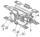
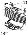
图8B为线缆整理器各个部件的爆炸图。Figure 8B is an exploded view of the various components of the cable organizer.
图中包括:The figure includes:
线缆限位槽1、上线缆座11、导向滑块111、定位卡槽112、卡接杆113、下线缆座12、导向滑轨121、定位卡扣122、角度限位块13、线缆盖2、线缆上盖21、调节滑块211、卡接口212、线缆下盖22、调节滑槽221、旋转弹簧3、旋转连接器4、连接环5、连接杆6。
具体实施方式Detailed ways
本发明的核心在于提供一种可调式自动收合线缆管理系统,能够应用于不同长度的线缆整理,适用性更强。The core of the present invention is to provide an adjustable automatic collapsing cable management system, which can be applied to cable arrangement of different lengths and has stronger applicability.
为了使本领域的技术人员更好地理解本发明的技术方案,下面将结合附图及具体的实施方式,对本发明的可调式自动收合线缆管理系统进行详细的介绍说明。In order to make those skilled in the art better understand the technical solutions of the present invention, the following describes the adjustable automatic retractable cable management system of the present invention in detail with reference to the accompanying drawings and specific embodiments.
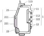
本发明提供一种可调式自动收合线缆管理系统,该系统包括多个线缆整理器,每个线缆整理器使线缆形成一个弯折;如图2A所示,为线缆整理器的结构示意图,图2B和图2C分别为线缆整理器和线缆相互配合的结构图。The present invention provides an adjustable automatic collapsing cable management system, which includes a plurality of cable organizers, each cable organizer forms a bend in the cable; as shown in FIG. 2A , it is a cable organizer FIG. 2B and FIG. 2C are the structural diagrams of the mutual cooperation between the cable organizer and the cable, respectively.
线缆整理器包括线缆限位槽1、线缆盖2、旋转弹簧3等结构,其中线缆限位槽1包括三个侧面围成的U型槽,如图3A至图3C所示,分别为线缆限位槽1三个不同状态的结构图;线缆限位槽1的横截面为U形,形成一个两端贯通的槽形结构,U型槽由三个侧面围成,线缆可从没有侧面的一侧放入U型槽,线缆沿U型槽的长度方向延伸布置。The cable organizer includes a
线缆盖2设置在U型槽没有缺少侧面的一侧,线缆盖2一端与线缆限位槽1转动连接,转轴方向与线缆的延伸方向大致平行,线缆盖 2的另一端能够与线缆限位槽1卡接,线缆盖2与线缆限位槽1卡接后与线缆限位槽1共同形成使线缆穿过的通道;线缆盖2的长度小于线缆限位槽1的长度,若线缆限位槽1的长度过长,可设置两个线缆盖2,通常一个线缆限位槽1上只需设置一个线缆盖2;线缆盖2打开时可以放入线缆,线缆盖2关闭时将线缆限位。The
一个线缆整理器包括至少包括两个线缆限位槽1,线缆限位槽1 之间相对转动连接,旋转弹簧3安装于两个线缆限位槽1的转动连接处,用于使两个线缆限位槽1具有合拢收缩的趋势,在不受其他外力的情况下,两个线缆限位槽1呈平行状态,如图4A所示,为两个线缆限位槽1呈平行状态的结构示意图;图4B为两个线缆限位槽1张开呈钝角的结构示意图;图4C为两个线缆限位槽1张开到最大角度的结构示意图;当线缆受到拉力时两个线缆限位槽1张开,拉力越大张开的角度越大。A cable organizer includes at least two
本发明的可调式自动收合线缆管理系统在一条线缆上设置多个线缆整理器,每个线缆整理器使线缆形成一个弯折,因此一条线缆通过多个线缆整理器形成多个弯折结构;由于线缆整理器具有折叠收缩的趋势,可将线缆弯折收缩,保持折叠的状态;当模块拉出服务器外时,线缆受到拉力趋于平直,此时两个线缆限位槽1的角度张开增大,满足模块被拉出的线缆长度要求;当模块被推回服务器时,线缆受到的拉力去除,在旋转弹簧3的弹力作用下,两个线缆限位槽1的角度收缩减小,线缆被折叠,保持服务器内部线缆的整洁。The adjustable and automatically retractable cable management system of the present invention is provided with a plurality of cable organizers on a cable, and each cable organizer makes the cable form a bend, so a cable passes through multiple cable organizers Multiple bending structures are formed; because the cable organizer has the tendency to fold and shrink, the cable can be bent and shrunk to keep the folded state; when the module is pulled out of the server, the cable tends to be straight due to the tension force. The angle of the two
本发明的可调式自动收合线缆管理系统中相邻的两个线缆整理器的间距可自由调节,因此不受机箱空间的限制,通过多个线缆整理器的相互配合,使一条线缆形成多处弯折结构,满足线缆折叠的要求,因此可以应用于不同长度的线缆整理,应用的灵活度更高。The distance between two adjacent cable organizers in the adjustable automatic collapsing cable management system of the present invention can be adjusted freely, so it is not limited by the space of the chassis. The cable forms multiple bending structures to meet the requirements of cable folding, so it can be applied to cable arrangement of different lengths, and the application is more flexible.
在上述方案的基础上,本发明在两个线缆限位槽1之间设置旋转连接器4,旋转连接器4分别转动连接于两个线缆限位槽1的端部,两个线缆限位槽1通过旋转连接器4实现转动连接,使两个线缆限位槽1能够相对旋转。当然,若线缆限位槽1的端部设置弯折的结构,也可将两个线缆限位槽1直接铰接相连。On the basis of the above solution, the present invention is provided with a
优选地,本发明中的线缆限位槽1为轴对称结构,线缆限位槽1 的两端均能够与旋转连接器4转动连接,加工制造时线缆限位槽1不分左右,采用相同的规格,节省加工成本,并且在组装时能够将任意两个线缆限位槽1与旋转连接器4相连,方便组装。Preferably, the
两个线缆限位槽1的端部设置角度限位块13,相邻两个线缆限位槽1上的两个角度限位块13能够相互抵接,以限定线缆整理器的张开角度,如图4D所示,为角度限位块13相互抵接的示意图;图中所示在线缆限位槽1的每端分别设置两个角度限位块13,当角度限位块13 相互抵接时线缆限位槽1无法继续张开,一方面限定了线缆的最大张角,另一方向避免旋转弹簧3过度变形。The ends of the two
如图5所示,为线缆限位槽1和线缆配合的结构示意图;线缆限位槽1的端部安装连接环5,图中所示在角度限位块13上设置开孔,开孔中安装连接环5,连接环5能够套在机箱上设置的线轨上,对线缆整理器整体导向限位。连接环5也可直接固定设置的线缆限位槽1上或者采用其他形式。As shown in FIG. 5 , it is a schematic diagram of the structure of the
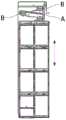
如图6A所示,为设置两排线轨的机箱内部模块的俯视结构图,图中设置两条线轨A,图中B表示线缆整理器,线轨的长度方向与模块的移动方向平行,也即图中的箭头方向,模块沿箭头向下移动时表示横移拉出,模块沿箭头向上移动时表示横移推入机箱。As shown in FIG. 6A, which is a top view of the internal module of the chassis with two rows of wire rails, two wire rails A are set in the figure, B in the figure represents the cable organizer, and the length direction of the wire rails is parallel to the moving direction of the module , that is, the direction of the arrow in the figure, when the module moves down along the arrow, it means that it is pulled out horizontally, and when the module moves up along the arrow, it means that it is pushed into the chassis horizontally.
图6A中设置两排线轨,每排线轨可导向多个线缆整理器,通过线轨使线缆整理器沿直线移动,并保持在线轨所限定的高度,不会因重力向下移动,保持线缆始终保持在同一高度上。In FIG. 6A, two rows of wire guides are provided, each row of wire guides can guide multiple cable organizers, and the cable organizers are moved in a straight line through the wire guides, and maintain the height defined by the wire guides, and will not move downward due to gravity , keep the cable at the same height at all times.
如图6B所示,为设置一排线轨的机箱内部模块的俯视结构图,对于某些空间条件不允许设置两条线轨的机箱,可仅设置一条线轨,为了能够对其他的线缆整理器进行限位,还设置有连接杆6,连接杆6 的一端直接或间接地连接于线缆限位槽1,另一端能够套在机箱上设置的线轨上;连接杆6可直接连接在线缆整理器上的开孔中,也可通过连接环5相连,这些具体的实施例均应包含在本发明的保护范围之内。As shown in Figure 6B, it is a top view of the internal module of the chassis with one row of line rails. For a case that does not allow two line rails to be installed in some space conditions, only one line rail can be provided. The organizer is limited, and is also provided with a connecting
线轨结构并非必须,如图6C所示,为不设置线轨的机箱内部模块的俯视结构图,不设置线轨可将线缆拉伸到时更长的长度。The wire rail structure is not necessary. As shown in FIG. 6C , it is a top view of the internal module of the chassis without wire rails. Without wire rails, the cables can be stretched to a longer length.
在上述任一技术方案及其相互组合的基础上,本发明的线缆限位槽1包括上线缆座11和下线缆座12,如图7A所示,为线缆限位槽1 的剖面结构图;上线缆座11和下线缆座12均为具有两个侧面形成的直角弯折结构,也即截面呈“L”型,由两块垂直的板面构成;上线缆座11和下线缆座12的其中一个侧面相互重叠,并能够相对滑动并定位,以调节上线缆座11和下线缆座12之间相互平行设置的两个侧面的距离,也即图7A中d的长度。On the basis of any of the above technical solutions and their combination, the
本发明在此提供一种上线缆座11和下线缆座12相互调动调节的具体设置形式,如图7B和图7C所示,分别为上线缆座11和下线缆座12处于第二挡和第三挡的剖面结构图;上线缆座11上设置导向滑块111和定位卡槽112,图中共设置三个定位卡槽112,每个定位卡槽112对应一挡,下线缆座12上设置导向滑轨121和定位卡扣122;导向滑块111卡入导向滑轨121内沿直线滑动,也即图7B和图7C中沿竖直方向上下滑动,定位卡扣122能够卡入不同的定位卡槽112以固定位置。The present invention hereby provides a specific arrangement form in which the
图7A所示处于第一挡,定位卡扣122与最上方的定位卡槽112 配合卡止,整个线缆限位槽1的竖向高度最小;图7B所示处于每二挡,相对于图7A沿箭头方向向上移动,定位卡扣122与中间的定位卡槽112配合卡止,线缆限位槽1的高度升高;图7C所示处于第三挡,相对于图7B沿箭头方向向上移动,定位卡扣122与最下方的定位卡槽112配合卡止,线缆限位槽1的高度进一步升高。Fig. 7A is in the first gear, the
本发明以设置三挡为例进行说明,也即设置三个不同高度的定位卡槽112,根据线缆的数量调节,以达到最佳匹配效果,防止线缆在线缆限位槽1中窜动。The present invention is described by taking the setting of the third gear as an example, that is, three positioning
如图8A所示,为线缆限位槽1的爆炸图;图8B为线缆整理器各个部件的爆炸图;线缆盖2包括线缆上盖21和线缆下盖22,线缆上盖21和线缆下盖22分体独立设置,线缆下盖22的一端与下线缆座 12铰接,也即图中线缆下盖22的下端与下线缆座12相互铰接,线缆下盖22可相对于下线缆座12转动。As shown in FIG. 8A, it is an exploded view of the
线缆下盖22上设置调节滑槽221,图中所示的调节滑槽221为沿线缆下盖22板面方向贯通设置的扁平的通孔,线缆上盖21上设置调节滑块211和卡接口212;调节滑块211能够卡入调节滑槽221,调节滑块211和调节滑槽221相互导向配合,调节滑块211沿调节滑槽221导向滑动,进而调节整个线缆上盖21的竖直位置。An
卡接口212能够卡接固定在上线缆座11上设置的卡接杆113上,卡接口212为圆柱形的凹槽,其横截面为优弧,能够产生弹性变形,进而卡在卡接杆113上,实现相对固定。The
当上线缆座11移动到不同的挡位于时,线缆上盖21能够相应地竖向移动,在三个挡位均能够与卡接杆113相互卡接固定。When the
对所公开的实施例的上述说明,使本领域专业技术人员能够实现或使用本发明。对这些实施例的多种修改对本领域的专业技术人员来说将是显而易见的,本文中所定义的一般原理,可以在不脱离本发明的精神或范围的情况下,在其它实施例中实现。因此,本发明将不会被限制于本文所示的这些实施例,而是要符合与本文所公开的原理和新颖特点相一致的最宽的范围。The above description of the disclosed embodiments enables any person skilled in the art to make or use the present invention. Various modifications to these embodiments will be readily apparent to those skilled in the art, and the general principles defined herein may be implemented in other embodiments without departing from the spirit or scope of the invention. Thus, the present invention is not intended to be limited to the embodiments shown herein, but is to be accorded the widest scope consistent with the principles and novel features disclosed herein.
Claims (9)
Translated fromChinesePriority Applications (1)
| Application Number | Priority Date | Filing Date | Title |
|---|---|---|---|
| CN202010980118.0ACN112099583B (en) | 2020-09-17 | 2020-09-17 | Adjustable automatic folding cable management system |
Applications Claiming Priority (1)
| Application Number | Priority Date | Filing Date | Title |
|---|---|---|---|
| CN202010980118.0ACN112099583B (en) | 2020-09-17 | 2020-09-17 | Adjustable automatic folding cable management system |
Publications (2)
| Publication Number | Publication Date |
|---|---|
| CN112099583Atrue CN112099583A (en) | 2020-12-18 |
| CN112099583B CN112099583B (en) | 2022-03-22 |
Family
ID=73760270
Family Applications (1)
| Application Number | Title | Priority Date | Filing Date |
|---|---|---|---|
| CN202010980118.0AActiveCN112099583B (en) | 2020-09-17 | 2020-09-17 | Adjustable automatic folding cable management system |
Country Status (1)
| Country | Link |
|---|---|
| CN (1) | CN112099583B (en) |
Citations (6)
| Publication number | Priority date | Publication date | Assignee | Title |
|---|---|---|---|---|
| KR100881221B1 (en)* | 2008-10-29 | 2009-02-05 | 유한회사 광진이엔지 | Cable supporting device of transmission line that is easy to install and dismantle |
| US20120152868A1 (en)* | 2010-12-15 | 2012-06-21 | Hon Hai Precision Industry Co., Ltd. | Cable management apparatus |
| CN202565629U (en)* | 2012-05-03 | 2012-11-28 | 天津视远科技发展有限公司 | Cabling channel |
| CN205488871U (en)* | 2016-01-08 | 2016-08-17 | 浙江宇视科技有限公司 | Structure is accomodate to cable |
| CN206595659U (en)* | 2017-02-28 | 2017-10-27 | 浪潮金融信息技术有限公司 | It is a kind of that there is the cabling slot structure for storing cable function |
| CN210666587U (en)* | 2019-11-08 | 2020-06-02 | 苏州浪潮智能科技有限公司 | A hard disk cable management device for plugging and unplugging a server hard disk module |
- 2020
- 2020-09-17CNCN202010980118.0Apatent/CN112099583B/enactiveActive
Patent Citations (6)
| Publication number | Priority date | Publication date | Assignee | Title |
|---|---|---|---|---|
| KR100881221B1 (en)* | 2008-10-29 | 2009-02-05 | 유한회사 광진이엔지 | Cable supporting device of transmission line that is easy to install and dismantle |
| US20120152868A1 (en)* | 2010-12-15 | 2012-06-21 | Hon Hai Precision Industry Co., Ltd. | Cable management apparatus |
| CN202565629U (en)* | 2012-05-03 | 2012-11-28 | 天津视远科技发展有限公司 | Cabling channel |
| CN205488871U (en)* | 2016-01-08 | 2016-08-17 | 浙江宇视科技有限公司 | Structure is accomodate to cable |
| CN206595659U (en)* | 2017-02-28 | 2017-10-27 | 浪潮金融信息技术有限公司 | It is a kind of that there is the cabling slot structure for storing cable function |
| CN210666587U (en)* | 2019-11-08 | 2020-06-02 | 苏州浪潮智能科技有限公司 | A hard disk cable management device for plugging and unplugging a server hard disk module |
Also Published As
| Publication number | Publication date |
|---|---|
| CN112099583B (en) | 2022-03-22 |
Similar Documents
| Publication | Publication Date | Title |
|---|---|---|
| US9891400B2 (en) | Pivotable cover for sliding tray and sliding tray including the cover | |
| DE3876421T2 (en) | ANGLE GUIDE. | |
| DE69521305T2 (en) | Container for a fiber optic distribution frame | |
| KR970002813B1 (en) | Optical fiber storage mechanism in optical cable terminal | |
| DE68903851T2 (en) | WELDING REEL. | |
| DE102010006611B4 (en) | Holder for at least one cassette | |
| JPH115387A (en) | Document holder | |
| DE7818648U1 (en) | Cable holder with strain relief | |
| DE102014109024A1 (en) | Duplex fiber optic connector | |
| KR20190077292A (en) | foldable electronic device having flexible display | |
| DE102019200724A1 (en) | Curvature control member and power supply device | |
| DE102006002909A1 (en) | Power supply apparatus | |
| JP2018530782A (en) | Cable routing device | |
| US8770532B2 (en) | Cable retaining ring having slide closure and cable support tray including the cable retaining ring | |
| DE102011118267A1 (en) | Movable grounding pin for mains plug with large size | |
| DE102005060339A1 (en) | Continuous power supply device | |
| CN112099583A (en) | Adjustable automatic folding cable management system | |
| US6463728B1 (en) | Cable guide | |
| DE3412159C2 (en) | Cassette-like device for accommodating the excess lengths required for making the connection of optical fibers | |
| CN112707253A (en) | Double-layer wire arranging device and server cabinet | |
| CN112499390A (en) | Communication cable protector | |
| CN113068340A (en) | Mounting device | |
| CN218216414U (en) | Cable wire clip | |
| CN217116686U (en) | Cable fixing mechanism and data processing device | |
| AT408291B (en) | CONNECTOR FOR CONTACTING THE WIRES OF STATOR WINDINGS OF AN ELECTRIC MOTOR |
Legal Events
| Date | Code | Title | Description |
|---|---|---|---|
| PB01 | Publication | ||
| PB01 | Publication | ||
| SE01 | Entry into force of request for substantive examination | ||
| SE01 | Entry into force of request for substantive examination | ||
| GR01 | Patent grant | ||
| GR01 | Patent grant | ||
| CP03 | Change of name, title or address | Address after:Building 9, No.1, guanpu Road, Guoxiang street, Wuzhong Economic Development Zone, Wuzhong District, Suzhou City, Jiangsu Province Patentee after:Suzhou Yuannao Intelligent Technology Co.,Ltd. Country or region after:China Address before:Building 9, No.1, guanpu Road, Guoxiang street, Wuzhong Economic Development Zone, Wuzhong District, Suzhou City, Jiangsu Province Patentee before:SUZHOU LANGCHAO INTELLIGENT TECHNOLOGY Co.,Ltd. Country or region before:China |