CN112099527B - A control method and system for autonomous landing of a vertical take-off and landing unmanned aerial vehicle mobile platform - Google Patents
A control method and system for autonomous landing of a vertical take-off and landing unmanned aerial vehicle mobile platformDownload PDFInfo
- Publication number
- CN112099527B CN112099527BCN202010978134.6ACN202010978134ACN112099527BCN 112099527 BCN112099527 BCN 112099527BCN 202010978134 ACN202010978134 ACN 202010978134ACN 112099527 BCN112099527 BCN 112099527B
- Authority
- CN
- China
- Prior art keywords
- landing
- mobile platform
- vertical take
- aerial vehicle
- unmanned aerial
- Prior art date
- Legal status (The legal status is an assumption and is not a legal conclusion. Google has not performed a legal analysis and makes no representation as to the accuracy of the status listed.)
- Active
Links
- 238000000034methodMethods0.000titleclaimsabstractdescription49
- 238000011426transformation methodMethods0.000claimsabstractdescription17
- 230000000007visual effectEffects0.000claimsabstractdescription15
- 239000011159matrix materialSubstances0.000claimsdescription42
- 230000001133accelerationEffects0.000claimsdescription3
- 230000002567autonomic effectEffects0.000claims1
- 230000004069differentiationEffects0.000claims1
- 230000009466transformationEffects0.000abstractdescription4
- 238000004880explosionMethods0.000abstractdescription2
- 238000010586diagramMethods0.000description9
- 230000008569processEffects0.000description8
- 230000006870functionEffects0.000description7
- 238000012986modificationMethods0.000description2
- 230000004048modificationEffects0.000description2
- 229920006395saturated elastomerPolymers0.000description2
- 230000009286beneficial effectEffects0.000description1
- 238000004891communicationMethods0.000description1
- 230000007547defectEffects0.000description1
- 230000005484gravityEffects0.000description1
- 238000007689inspectionMethods0.000description1
- 230000008447perceptionEffects0.000description1
- 230000003068static effectEffects0.000description1
- 230000001052transient effectEffects0.000description1
Images


Classifications
- G—PHYSICS
- G05—CONTROLLING; REGULATING
- G05D—SYSTEMS FOR CONTROLLING OR REGULATING NON-ELECTRIC VARIABLES
- G05D1/00—Control of position, course, altitude or attitude of land, water, air or space vehicles, e.g. using automatic pilots
- G05D1/10—Simultaneous control of position or course in three dimensions
- G05D1/101—Simultaneous control of position or course in three dimensions specially adapted for aircraft
- G05D1/102—Simultaneous control of position or course in three dimensions specially adapted for aircraft specially adapted for vertical take-off of aircraft
Landscapes
- Engineering & Computer Science (AREA)
- Aviation & Aerospace Engineering (AREA)
- Radar, Positioning & Navigation (AREA)
- Remote Sensing (AREA)
- Physics & Mathematics (AREA)
- General Physics & Mathematics (AREA)
- Automation & Control Theory (AREA)
- Control Of Position, Course, Altitude, Or Attitude Of Moving Bodies (AREA)
Abstract
Translated fromChinese
Description
Translated fromChinese技术领域technical field
本发明涉及垂直起降无人机自主着陆领域,特别是一种垂直起降无人机在移动平台上自主着陆的控制方法及系统。The invention relates to the field of autonomous landing of vertical take-off and landing drones, in particular to a control method and system for autonomous landing of vertical take-off and landing drones on a mobile platform.
背景技术Background technique
垂直起降无人机在民用和军用场景中得到了广泛的应用,包括工业检查、航空摄影、通信中继、监视、搜索和救援等。无人机的自主着陆为机载自动飞行系统完全控制航空器,进行着陆飞行的过程。而在该过程中,操纵复杂,地面干扰因素多,需要无人机具有高精度自主定位导航、鲁棒着陆轨迹跟踪能力。VTOL UAVs are widely used in civil and military scenarios, including industrial inspection, aerial photography, communication relay, surveillance, search and rescue, etc. The autonomous landing of the UAV is the process in which the airborne automatic flight system completely controls the aircraft and performs the landing flight. In this process, the manipulation is complex and there are many ground interference factors, which requires the UAV to have high-precision autonomous positioning and navigation and robust landing trajectory tracking capabilities.
目前,更多的是研究了针对静态平台的姿势估计方法,但是考虑到更一般的应用,当垂直起降无人机降落在移动平台上时,则自主着陆控制系统的难度进一步增加。Currently, pose estimation methods for static platforms are more studied, but considering more general applications, when the VTOL UAV lands on a mobile platform, the difficulty of the autonomous landing control system is further increased.
在设计无人机自主着陆控制系统时,需要准确估计着陆目标相对于本地环境的位姿,同时设计满足着陆任务约束的控制器。但由于垂直起降无人机的有效载荷特性较低,其机载传感器和计算能力受限,如何在低负载、低计算能力情况下设计较高精度的自主着陆控制系统成为急需解决的问题。When designing the UAV autonomous landing control system, it is necessary to accurately estimate the pose of the landing target relative to the local environment, and at the same time design a controller that satisfies the constraints of the landing task. However, due to the low payload characteristics of vertical take-off and landing UAVs, its on-board sensors and computing capabilities are limited. How to design a high-precision autonomous landing control system under low load and low computing capabilities has become an urgent problem to be solved.
发明内容SUMMARY OF THE INVENTION
本发明要解决的技术问题是,克服现有技术存在的上述缺陷,提供一种垂直起降无人机在移动平台自主着陆的控制方法及系统,提高无人机控制精度,简化机载感知工具,降低控制方法复杂度。The technical problem to be solved by the present invention is to overcome the above-mentioned defects in the prior art, and to provide a control method and system for autonomous landing of a vertical take-off and landing drone on a mobile platform, which improves the control accuracy of the drone and simplifies the airborne perception tool. , reduce the complexity of the control method.
本发明进一步要解决的技术问题是,在提供上述自主着陆的控制方法的基础上,还提供一种包括上述控制方法的系统。A further technical problem to be solved by the present invention is to provide a system including the above control method in addition to the above control method for autonomous landing.
本发明解决技术问题采用的技术方案是:提供一种垂直起降无人机在移动平台上自主着陆的控制方法,包括以下步骤:The technical solution adopted by the present invention to solve the technical problem is to provide a control method for autonomous landing of a vertical take-off and landing drone on a mobile platform, comprising the following steps:
S1:建立垂直起降无人机的动力学模型、移动平台的运动学模型以及垂直起降无人机与移动平台的相对运动学模型;S1: Establish the dynamic model of the VTOL UAV, the kinematic model of the mobile platform, and the relative kinematics model of the VTOL UAV and the mobile platform;
S2:设计预定性能规范误差变换方法;S2: Design the predetermined performance specification error transformation method;
S3:采用基于预定性能规范误差变换方法的反演控制方法设计得到垂直起降无人机的位置控制律;S3: Using the inversion control method based on the predetermined performance specification error transformation method to design the position control law of the VTOL UAV;
S4:设计期望旋转矩阵,及期望角速度;S4: Design the desired rotation matrix, and the desired angular velocity;
S5:计算垂直起降无人机在移动平台上自动着陆所需要的力矩,实现自主着陆控制。S5: Calculate the torque required for the VTOL UAV to automatically land on the mobile platform, and realize autonomous landing control.
进一步的,所述步骤S1包括以下步骤:Further, the step S1 includes the following steps:
S11:建立垂直起降无人机的动力学模型,模型描述为:S11: Establish the dynamic model of the vertical take-off and landing UAV, the model is described as:


其中,p=[px,py,pz]T是垂直起降无人机在世界坐标系中的三维位置,

S12:建立移动平台的运动学模型,模型描述为:S12: Establish a kinematic model of the mobile platform, the model is described as:

其中,rl=[xl,yl,h]T表示移动平台在世界坐标系中的位置,xl是移动平台的横坐标,yl是移动平台的纵坐标,h是移动平台的高度,θl是移动平台本体坐标系相对于世界坐标系的旋转角度,vl和ωl分别表示移动平台的线速度和角速度;Among them, rl =[xl ,yl ,h]T represents the position of the mobile platform in the world coordinate system, xl is the abscissa of the mobile platform, yl is the ordinate of the mobile platform, h is the height of the mobile platform , θl is the rotation angle of the mobile platform body coordinate system relative to the world coordinate system, vl and ωl represent the linear velocity and angular velocity of the mobile platform, respectively;
S13:建立垂直起降无人机与移动平台的相对运动学模型,模型描述为:S13: Establish the relative kinematics model of the VTOL UAV and the mobile platform. The model is described as:
rlp=p-rl (6)rlp =prl (6)
其中,rlp=[xlp,ylp,zlp]T是垂直起降无人机和移动平台的实时相对三维位置。where rlp =[xlp , ylp , zlp ]T is the real-time relative three-dimensional position of the VTOL UAV and the mobile platform.
进一步的,所述步骤S2预定性能误差变换方法为:Further, the predetermined performance error transformation method in step S2 is:

其中,ζk=ek/ρk,ek为定义的误差,εk为变换后的误差,ρk为误差性能函数,k∈{1,2,…6}。Among them, ζk =ek /ρk ,ek is the defined error, εk is the transformed error, ρk is the error performance function, k∈{1, 2,...6}.
进一步的,所述步骤S3包括以下步骤:Further, the step S3 includes the following steps:
S31:垂直起降无人机搭载的单目视觉装置捕获移动平台上设置的AprilTag视觉系统中的AprilTag视觉标志信息,根据已知的AprilTag视觉标志物理尺寸,由单应矩阵得到垂直起降无人机和移动平台之间的实时相对三维位置rlp=[xlp,ylp,zlp]T和姿态信息;S31: The monocular vision device mounted on the VTOL UAV captures the AprilTag visual sign information in the AprilTag vision system set on the mobile platform. According to the known physical size of the AprilTag visual sign, the VTOL unmanned aerial vehicle is obtained from the homography matrix. Real-time relative three-dimensional position rlp =[xlp , ylp , zlp ]T and attitude information between the machine and the mobile platform;
S32:定义位置误差ep=[e1,e2,e3]T为:S32: Define the position error ep= [e1 , e2 , e3 ]T as:

其中,
S33:根据预定性能规范误差变换方法,得到变换后的位置误差εp=[ε1,ε2,ε3]T;S33: Obtain the transformed position error εp =[ε1 ,ε2 ,ε3 ]T according to the predetermined performance specification error transformation method;
S34:对变换后的位置误差中求一阶微分式可得:S34: Find the first-order differential in the transformed position error to get:

其中,


S35:设置虚拟期望垂直起降无人机的线速度为

其中,K1、K2均为中间控制器的增益;Among them, K1 and K2 are the gains of the intermediate controller;
S36:定义速度误差ev=[e4,e5,e6]T为:S36: Define the speed error ev = [e4 , e5 , e6 ]T as:

S37:根据预定性能误差变换方法,得到变换后的速度误差εv=[ε4,ε5,ε6]T,对变换后的速度误差求一阶微分式可得:S37: According to the predetermined performance error transformation method, the transformed velocity error εv =[ε4 ,ε5 ,ε6 ]T is obtained, and the first-order differential formula of the transformed velocity error can be obtained:

其中,Qv=diag(q4,q5,q6)与ηv=(η4,η5,η6)T分别被定义为:Among them, Qv =diag(q4 ,q5 ,q6 ) and ηv =(η4 ,η5 ,η6 )T are respectively defined as:


S38:依据式(14)及式(2),设计位置控制律为:S38: According to formula (14) and formula (2), the design position control law is:
u=-(K3QvT+Qv-1K4)εv (17)u=-(K3 QvT +Qv-1 K4 )εv (17)
其中,K3,K4是正定矩阵。Among them, K3 , K4 are positive definite matrices.
进一步的,所述步骤S4具体包括以下步骤:Further, the step S4 specifically includes the following steps:
S41:设置期望旋转角度ψ*=0;S41: set the desired rotation angle ψ* =0;
S42:根据推力向量F=mgi3-mu和期望旋转角度向量y=[cosψ*,sinψ*,0]T,设计期望旋转矩阵为Rd=[r1,r2,r3],其中S42: According to the thrust vector F=mgi3 -mu and the desired rotation angle vector y=[cosψ* , sinψ* ,0]T , design the desired rotation matrix as Rd =[r1 , r2 , r3 ], where

S44:推力向量的一阶微分式表示为


其中,Kα是一个正定对称矩阵;where Kα is a positive definite symmetric matrix;
S43:期望角速度表示为:S43: Desired angular velocity is expressed as:

其中,(·)∨表示为(·)∧的逆操作,


I3×3是3阶单位矩阵。I3×3 is an identity matrix of
进一步的,所述步骤S5具体包括以下步骤:Further, the step S5 specifically includes the following steps:
S51:将式(2)改写为:S51: Rewrite formula (2) as:


依据式(17),则垂直起降无人机的饱和推力设计为:According to formula (17), the saturated thrust of the VTOL UAV is designed as:

S52:旋转矩阵的误差项定义如下:S52: The error term of the rotation matrix is defined as follows:

eΩ=Ω-RTRdΩd (26)eΩ =Ω-RT Rd Ωd (26)
其中,Rd为期望旋转矩阵,R为实际旋转矩阵,eR为旋转矩阵误差;Ωd为期望角速度,Ω为实际角速度,eΩ为角速度误差;Among them, Rd is the expected rotation matrix, R is the actual rotation matrix, eR is the rotation matrix error; Ωd is the expected angular velocity, Ω is the actual angular velocity, and eΩ is the angular velocity error;
S53:结合式(4)、式(25)、式(26),得到垂直起降无人机的力矩为:S53: Combining formula (4), formula (25), and formula (26), the torque of the VTOL UAV is obtained as:
τ=-KReR-KΩeΩ+Ω×JΩ (27)τ=-KR eR -KΩ eΩ +Ω×JΩ (27)
其中,KR、KΩ为姿态控制增益。Among them, KR and KΩ are attitude control gains.
本发明还提供一种垂直起降无人机在移动平台上自主着陆的系统,所述系统包含垂直起降无人机、单目视觉装置、自主着陆控制模块、AprilTag视觉基准系统、移动平台,其中:The present invention also provides a system for autonomous landing of a vertical take-off and landing drone on a mobile platform, the system comprising a vertical take-off and landing drone, a monocular vision device, an autonomous landing control module, an AprilTag visual reference system, and a mobile platform, in:
所述单目视觉装置与所述自主着陆控制模块相连,单目视觉装置将采集的图像信息发送给自主着陆控制模块;所述自主着陆控制模块与所述垂直起降无人机相连,将控制指令发送给垂直起降无人机;所述移动平台上设置AprilTag视觉基准系统;所述AprilTag视觉基准系统处于单目视觉装置视角范围内。The monocular vision device is connected to the autonomous landing control module, and the monocular vision device sends the collected image information to the autonomous landing control module; the autonomous landing control module is connected to the vertical take-off and landing unmanned aerial vehicle to control the The instruction is sent to the vertical take-off and landing unmanned aerial vehicle; the AprilTag visual reference system is set on the mobile platform; the AprilTag visual reference system is within the viewing angle range of the monocular vision device.
进一步的,所述垂直升降无人机为四旋翼无人机。Further, the vertical lift unmanned aerial vehicle is a quadrotor unmanned aerial vehicle.
进一步的,所述单目视觉装置为单目相机。Further, the monocular vision device is a monocular camera.
本发明的有益效果为:通过采用单目相机和AprilTag视觉基准系统估计移动平台相对于垂直起降无人机的精确三维位置和姿态,简化了机载传感器的数量,使得垂直起降无人机载负荷低;同时设计的一种预定性能误差变换方法,保证输出误差沿绝对衰减时间函数收敛到预定义的残差集,并且最大过冲低于预定水平,而基于误差变换的反演控制方法有效解决其他反演控制方法中常用术语组合爆炸的问题,提高了估计的精度,有效提升了垂直升降无人机在移动平台自主着陆的机动性。The beneficial effects of the present invention are: by using the monocular camera and the AprilTag visual reference system to estimate the precise three-dimensional position and attitude of the mobile platform relative to the VTOL UAV, the number of airborne sensors is simplified, so that the VTOL UAV can be At the same time, a predetermined performance error transformation method is designed to ensure that the output error converges to a predefined residual set along the absolute decay time function, and the maximum overshoot is lower than the predetermined level, while the inversion control method based on error transformation It effectively solves the problem of combinatorial explosion of commonly used terms in other inversion control methods, improves the estimation accuracy, and effectively improves the maneuverability of the vertical lift UAV for autonomous landing on a mobile platform.
附图说明Description of drawings
图1为本发明提供的一种垂直起降无人机在移动平台上自主着陆的控制方法的流程框图;Fig. 1 is a flow chart of a control method for autonomous landing of a vertical take-off and landing drone on a mobile platform provided by the present invention;
图2为本发明提供的一种垂直起降无人机在移动平台上自主着陆的控制方法系统框架示意图;2 is a schematic diagram of a system framework of a control method for autonomous landing of a vertical take-off and landing drone on a mobile platform provided by the present invention;
图3为本发明提供的一种垂直起降无人机在移动平台上自主着陆的控制方法的自主着陆轨迹三维示意图;3 is a three-dimensional schematic diagram of an autonomous landing trajectory of a control method for autonomous landing of a vertical take-off and landing drone on a mobile platform provided by the present invention;
图4为本发明提供的一种垂直起降无人机在移动平台上自主着陆的控制方法相对位置误差e1收敛过程示意图;4 is a schematic diagram of the convergence process of the relative position error e1 of a control method for autonomous landing of a vertical take-off and landing drone on a mobile platform provided by the present invention;
图5为本发明提供的一种垂直起降无人机在移动平台上自主着陆的控制方法相对位置误差e2收敛过程示意图;5 is a schematic diagram of the convergence process of the relative position error e2 of a control method for autonomous landing of a vertical take-off and landing drone on a mobile platform provided by the present invention;
图6为本发明提供的一种垂直起降无人机在移动平台上自主着陆的控制方法相对位置误差e3收敛过程示意图;6 is a schematic diagram of the convergence process of the relative position error e3 of a control method for autonomous landing of a vertical take-off and landing drone on a mobile platform provided by the present invention;
图7为本发明提供的一种垂直起降无人机在移动平台上自主着陆的控制方法垂直起降无人机速度误差e4收敛过程示意图;7 is a schematic diagram of the convergence process of the speed error e4 of the vertical take-off and landing drone of a control method for autonomous landing of a vertical take-off and landing drone on a mobile platform provided by the present invention;
图8为本发明提供的一种垂直起降无人机在移动平台上自主着陆的控制方法垂直起降无人机速度误差e5收敛过程示意图;8 is a schematic diagram of the convergence process of the speed error e5 of the vertical take-off and landing drone of a control method for autonomous landing of a vertical take-off and landing drone on a mobile platform provided by the present invention;
图9为本发明提供的一种垂直起降无人机在移动平台上自主着陆的控制方法垂直起降无人机速度误差e6收敛过程示意图;9 is a schematic diagram of the convergence process of the speed error e6 of the vertical take-off and landing drone of a control method for autonomous landing of a vertical take-off and landing drone on a mobile platform provided by the present invention;
图10为本发明提供的一种垂直起降无人机在移动平台上自主着陆的系统示意图。10 is a schematic diagram of a system for autonomous landing of a vertical take-off and landing drone on a mobile platform provided by the present invention.
具体实施方式Detailed ways
为了使本技术领域的人员更好地理解本发明的技术方案,下面结合附图对本发明作进一步的详细说明。In order to make those skilled in the art better understand the technical solutions of the present invention, the present invention will be further described in detail below with reference to the accompanying drawings.
参考图1、图2,图1为本发明提供的一种垂直起降无人机在移动平台上自主着陆的控制方法的流程框图,包括以下几个步骤:Referring to Figure 1 and Figure 2, Figure 1 is a flowchart of a control method for a vertical take-off and landing drone provided by the present invention to land autonomously on a mobile platform, including the following steps:
S1:建立垂直起降无人机的动力学模型、移动平台的运动学模型以及垂直起降无人机与移动平台的相对运动学模型;S1: Establish the dynamic model of the VTOL UAV, the kinematic model of the mobile platform, and the relative kinematics model of the VTOL UAV and the mobile platform;
S2:设计预定性能误差变换方法;S2: Design a predetermined performance error transformation method;
S3:采用基于预定性能误差变换方法的反演控制方法设计得到垂直起降无人机的位置控制律;S3: Using the inversion control method based on the predetermined performance error transformation method to design the position control law of the vertical take-off and landing UAV;
S4:设计期望旋转矩阵及期望角速度;S4: Design the desired rotation matrix and the desired angular velocity;
S5:计算垂直起降无人机在移动平台上自动着陆所需要的力矩。S5: Calculate the torque required for the VTOL UAV to automatically land on the mobile platform.
进一步的,所述步骤S1包括以下步骤:Further, the step S1 includes the following steps:
S11:建立垂直起降无人机的动力学模型,模型描述为:S11: Establish the dynamic model of the vertical take-off and landing UAV, the model is described as:


其中,p=[px,py,pz]T是垂直起降无人机在世界坐标系中的三维位置,v=[vx,vy,vz]T是垂直起降无人机在世界坐标系下的线速度,Ω=[Ωx,Ωy,Ωz]T是垂直起降无人机在本体坐标系下的角速度,Ω∧表示角速度的斜对称矩阵,使得RΩ∧=R×Ω,m和J=diag(J1,J2,J3)分别表示垂直起降无人机的质量和惯性矩阵,设定m=1.5,J=diag(0.0095,0.0095,0.019),g是重力加速度,i3=[0,0,1]T是单位向量,推力和扭力分别为f和τ=[τx,τy,τz]T。旋转矩阵R是由垂直起降无人机沿欧拉角ψ,φ,θ旋转得到,这三个角分别表示为偏航角,滚转角与俯仰角。Among them, p=[px , py , pz ]T is the three-dimensional position of the vertical take-off and landing UAV in the world coordinate system, v=[vx , vy , vz ]T is the vertical take-off and landing unmanned aerial vehicle The linear velocity of the aircraft in the world coordinate system, Ω=[Ωx ,Ωy ,Ωz ]T is the angular velocity of the vertical take-off and landing UAV in the body coordinate system, Ω∧ represents the oblique symmetric matrix of the angular velocity, such that RΩ∧ =R×Ω, m and J=diag(J1 , J2 , J3 ) represent the mass and inertia matrix of the VTOL UAV respectively, set m=1.5, J=diag(0.0095, 0.0095, 0.019) , g is the gravitational acceleration, i3 =[0,0,1]T is a unit vector, and the thrust and torsion forces are f and τ=[τx ,τy ,τz ]T , respectively. The rotation matrix R is obtained by rotating the VTOL UAV along the Euler angles ψ, φ, and θ. These three angles are represented as yaw angle, roll angle and pitch angle respectively.
S12:考虑非完整约束,建立移动平台的运动学模型,模型描述为:S12: Considering the nonholonomic constraints, establish a kinematic model of the mobile platform. The model is described as:

其中,rl=[xl,yl,h]T表示移动平台在世界坐标系中的位置,h是移动平台的高度,θl是移动平台本体坐标系相对于世界坐标系的旋转角度,vl和ωl分别表示移动平台的线速度和角速度,设置vl=0.4,ωl=0.2。Among them, rl =[xl ,yl ,h]T represents the position of the mobile platform in the world coordinate system, h is the height of the mobile platform, θl is the rotation angle of the mobile platform body coordinate system relative to the world coordinate system, vl and ωl represent the linear velocity and angular velocity of the moving platform, respectively, and set vl =0.4 and ωl =0.2.
S13:建立垂直起降无人机与移动平台的相对运动学模型,模型描述为:S13: Establish the relative kinematics model of the VTOL UAV and the mobile platform. The model is described as:
rlp=p-rl (6)rlp =prl (6)
其中,rlp=[xlp,ylp,zlp]T是垂直起降无人机和移动平台的相对三维位置。Among them, rlp =[xlp , ylp , zlp ]T is the relative three-dimensional position of the VTOL UAV and the mobile platform.
进一步的,所述步骤S2预定性能误差变换方法为:Further, the predetermined performance error transformation method in step S2 is:

其中,ζk=ek/ρk,ek为定义的误差,εk为变换后的误差,ρk为误差性能函数,k∈{1,2,...6};Among them, ζk =ek /ρk ,ek is the defined error, εk is the transformed error, ρk is the error performance function, k∈{1, 2,...6};
其设计方法为:首先,定义误差为ek(t),为保证误差沿绝对衰减的时间函数收敛到预定义的残差集,用误差性能函数ρk(t)定义相对误差ek(t)的边界:The design method is as follows: First, the error is defined as ek (t), in order to ensure that the error converges to a predefined residual set along the time function of absolute decay, the relative error ek (t) is defined by the error performance function ρk (t). ) boundaries:

接着,误差性能函数ρk(t)由下式定义:Next, the error performance function ρk (t) is defined by:
ρk(t)=(ρk(0)-ρ∞)e-lt+ρ∞ (9)ρk (t)=(ρk (0)-ρ∞ )e-lt +ρ∞ (9)
其中,ρk(0)表示起始允许的最大误差,初始误差满足0<|ek(0)|<ρk(0),指数系数l>0,ρ∞表示稳态最大误差。位置最大允许稳态误差设置为ρ∞=0.02,收敛速度按指数收敛,其指数系数设置为l=1,速度最大允许稳态误差设置为ρ∞=0.05,收敛速度按指数收敛,其指数系数设置为l=1。Among them, ρk (0) represents the maximum allowable initial error, the initial error satisfies 0<|ek (0)|<ρk (0), the exponential coefficient l>0, and ρ∞ represents the steady-state maximum error. The maximum allowable steady-state error of the position is set to ρ∞ = 0.02, the convergence speed is exponentially converged, and its exponential coefficient is set to l = 1, the maximum allowable steady-state error of the speed is set to ρ∞ = 0.05, the convergence speed is exponentially converged, and its exponential coefficient Set to l=1.
为设计具有预定性能规范的误差变换,误差按下式设定:To design an error transform with predetermined performance specifications, the error is set as:
ek(t)=ρk(t)T(εk) (10)ek (t)=ρk (t)T(εk ) (10)
其中,T(εk)是一个光滑连续的单调递增函数,并且满足:where T(εk ) is a smooth continuous monotonically increasing function that satisfies:

根据上述要求,T(εk)表示为:According to the above requirements, T(εk ) is expressed as:

定义ζk=ek/ρk,依据式(12)得到T(εk)的反函数,表示为:Define ζk =ek /ρk , according to formula (12), the inverse function of T(εk ) is obtained, which is expressed as:

进一步的,所述估计移动平台相对于垂直起降无人机的精确三维位置和姿态为通过垂直起降无人机搭载一个单目相机,移动平台上设置一个可视AprilTag(视觉基准系统)标志,根据已知标志的物理尺寸,由单应矩阵获取移动平台和垂直起降无人机之间的相对位置rlp=[xlp,ylp,zlp]T与姿态,获取的rlp=[2,2,1.7]T。Further, the accurate three-dimensional position and attitude of the estimated mobile platform relative to the vertical take-off and landing drone is to carry a monocular camera through the vertical take-off and landing drone, and a visible AprilTag (visual reference system) mark is set on the mobile platform. , According to the physical size of the known sign, the relative position between the mobile platform and the VTOL UAV is obtained from the homography matrix rlp = [xlp , ylp , zlp ]T and attitude, the obtained rlp = [2,2,1.7]T .
进一步的,所述步骤S3通过预定性能误差变换函数的反演控制方法包括以下步骤:Further, the step S3 includes the following steps through the inversion control method of the predetermined performance error transformation function:
S31:垂直起降无人机搭载的单目视觉装置捕获移动平台上设置的AprilTag视觉系统中的AprilTag视觉标志信息,根据已知的AprilTag视觉标志物理尺寸,由单应矩阵得到移动平台和垂直起降无人机之间的实时相对位置rlp=[xlp,ylp,zlp]T和姿态信息,本实施例获取的rlp=[2,2,1.7]T;S31: The monocular vision device mounted on the VTOL UAV captures the AprilTag visual sign information in the AprilTag vision system set on the mobile platform. According to the known physical size of the AprilTag visual sign, the mobile platform and the vertical starting point are obtained from the homography matrix. Real-time relative position rlp =[xlp , ylp , zlp ]T and attitude information between the landing drones, rlp =[2, 2, 1.7]T obtained in this embodiment;
S32:定义位置误差ep=[e1,e2,e3]T为:S32: Define the position error ep= [e1 , e2 , e3 ]T as:

其中,

S33:根据预定性能误差变换方法,得到变换后的位置误差εp=[ε1,ε2,ε3]T;S33: Obtain the transformed position error εp =[ε1 ,ε2 ,ε3 ]T according to the predetermined performance error transformation method;
S34:对变换误差求一阶微分式可得:S34: Calculate the first-order differential for the transformation error to get:

其中,


S35:假设虚拟速度控制变量定义为

其中,K1,K2是正定矩阵,为中间控制器的增益,设置为K1=diag(0.01,0.01,0.01)和K2=diag(2,2,2),Q=diag(q1,q2,q3),εp为变换后的位置误差;Among them, K1 , K2 are positive definite matrices, which are the gains of the intermediate controller, set as K1 =diag(0.01, 0.01, 0.01) and K2 =diag(2, 2, 2), Q=diag(q1 , q2 , q3 ), εp is the transformed position error;
S36:定义速度误差ev=[e4,e5,e6]T为:S36: Define the speed error ev = [e4 , e5 , e6 ]T as:

S37:根据预定性能误差变换方法,得到变换后的速度误差εv=[ε4,ε5,ε6]T,对变换后的速度误差求一阶微分式可得:S37: According to the predetermined performance error transformation method, the transformed velocity error εv =[ε4 ,ε5 ,ε6 ]T is obtained, and the first-order differential formula of the transformed velocity error can be obtained:

其中,Qv=diag(q4,q5,q6)与ηv=(η4,η5,η6)T分别被定义为:Among them, Qv =diag(q4 ,q5 ,q6 ) and ηv =(η4 ,η5 ,η6 )T are respectively defined as:


S38:依据式(20)及式(2),设计位置控制律为:S38: According to formula (20) and formula (2), the design position control law is:
u=-(K3QvT+Qv-1K4)εv (23)u=-(K3 QvT +Qv-1 K4 )εv (23)
其中,K3,K4是正定矩阵,为位置控制器的增益,设置为K3=diag(0.01,0.01,0.01)和K4=diag(10,10,10)。Wherein, K3 , K4 are positive definite matrices, which are the gains of the position controller, and are set as K3 =diag(0.01, 0.01, 0.01) and K4 =diag(10, 10, 10).
进一步的,所述步骤S4具体包括以下步骤:Further, the step S4 specifically includes the following steps:
S41:考虑四旋翼无人机的物理结构对称,在降落在移动平台上时,其旋转角度不影响自主着陆的性能要求,设置期望旋转角度ψ*=0。S41: Considering the symmetry of the physical structure of the quadrotor UAV, when landing on a mobile platform, its rotation angle does not affect the performance requirements of autonomous landing, and the desired rotation angle ψ* =0 is set.
S42:根据推力向量F=mgi3-mu和期望旋转角度向量y=[cosψ*,sinψ*,0]T,设计期望旋转矩阵为Rd=[r1,r2,r3],其中S42: According to the thrust vector F=mgi3 -mu and the desired rotation angle vector y=[cosψ* , sinψ* ,0]T , design the desired rotation matrix as Rd =[r1 , r2 , r3 ], where

S43:期望角速度表示为:S43: Desired angular velocity is expressed as:

其中,(·)∨表示为(·)∧的逆操作,使得


S44:推力向量的一阶微分式表示为


其中,Kα是一个正定对称矩阵,为低通滤波器的增益,设置Kα=0.01,I3×3是3阶单位矩阵。Among them, Kα is a positive definite symmetric matrix, which is the gain of the low-pass filter, set Kα =0.01, and I3×3 is a third-order unit matrix.
进一步的,所述步骤S5具体包括以下内容:Further, the step S5 specifically includes the following content:
S51:将式(2)改写为:S51: Rewrite formula (2) as:


依据式(23),则垂直起降无人机的饱和推力设计为:According to formula (23), the saturated thrust of VTOL UAV is designed as:

S45:旋转矩阵的误差项定义如下:S45: The error term of the rotation matrix is defined as follows:

eΩ=Ω-RTRdΩd (32)eΩ =Ω-RT Rd Ωd (32)
其中,Rd为期望旋转矩阵,R为实际旋转矩阵,eR为旋转矩阵误差;Ωd为期望角速度,Ω为实际角速度,eΩ为角速度误差;Among them, Rd is the expected rotation matrix, R is the actual rotation matrix, eR is the rotation matrix error; Ωd is the expected angular velocity, Ω is the actual angular velocity, and eΩ is the angular velocity error;
S52:结合式(4)、式(31)、式(32),得到垂直起降无人机的扭力设计为:S52: Combining formula (4), formula (31), and formula (32), the torque design of the VTOL UAV is obtained as:
τ=-KReR-KΩeΩ+Ω×JΩ (33)τ=-KR eR -KΩ eΩ +Ω×JΩ (33)
姿态控制器的增益设置为KR=diag(150,150,150)和KΩ=diag(1.5,1.5,1.5)。The gain of the attitude controller is set to KR =diag(150, 150, 150) andKΩ =diag(1.5, 1.5, 1.5).
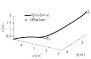
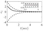
参考图3,显示了采用上述方法控制的垂直升降无人机自主着陆的完整三维轨迹,其中Qs和Ps分别表示垂直升降无人机和移动平台的初始位置。参考图4、图5、图6,相对位置误差沿绝对衰减时间函数快速收敛,参考图7、图8、图9,速度误差沿绝对衰减时间函数快速收敛。上述结果表明,垂直起降无人机移动自主着陆算法具有良好的瞬态、稳态性能。Referring to Fig. 3, the complete 3D trajectory of the autonomous landing of the VTOL UAV controlled by the above method is shown, where Qs and Ps represent the initial positions of the VTOL UAV and the mobile platform, respectively. Referring to Figures 4, 5, and 6, the relative position error converges rapidly along the absolute decay time function, and with reference to Figures 7, 8, and 9, the velocity error rapidly converges along the absolute decay time function. The above results show that the VTOL UAV mobile autonomous landing algorithm has good transient and steady-state performance.
参考图10,提供一种垂直起降无人机在移动平台上自主着陆的系统,所述系统包含垂直起降无人机1、单目视觉装置2、自主着陆控制模块3、AprilTag视觉基准系统4、移动平台5,其中:所述单目视觉装置2与所述自主着陆控制模块3相连,单目视觉装置2将采集的图像信息发送给自主着陆控制模块3;所述自主着陆控制模块3与所述垂直起降无人机1相连,将控制指令发送给垂直起降无人机1;所述移动平台5上设置AprilTag视觉基准系统4;Referring to FIG. 10 , a system for autonomous landing of a vertical take-off and landing drone on a mobile platform is provided. The system includes a vertical take-off and
进一步的,所述垂直升降无人机为四旋翼无人机。Further, the vertical lift unmanned aerial vehicle is a quadrotor unmanned aerial vehicle.
进一步的,所述单目视觉装置为单目相机。Further, the monocular vision device is a monocular camera.
以上对本发明所提供的一种垂直起降无人机在移动平台上自主着陆的方法和系统进行了详细介绍,并通过实施例对本发明的具体原理及实施方式进行了阐述,这些说明只是用于帮助理解本发明的核心思想。应当指出,对于本技术领域的普通技术人员来说,在不脱离本发明原理的前提下,还可以对本发明进行若干改进和修饰,这些改进和修饰也属于本发明权利要求的保护范围。The method and system for autonomous landing of a vertical take-off and landing drone on a mobile platform provided by the present invention are described above in detail, and the specific principles and implementations of the present invention are described through examples. These descriptions are only used for Help to understand the core idea of the present invention. It should be pointed out that for those skilled in the art, without departing from the principle of the present invention, several improvements and modifications can also be made to the present invention, and these improvements and modifications also belong to the protection scope of the claims of the present invention.
Claims (8)


Priority Applications (1)
| Application Number | Priority Date | Filing Date | Title |
|---|---|---|---|
| CN202010978134.6ACN112099527B (en) | 2020-09-17 | 2020-09-17 | A control method and system for autonomous landing of a vertical take-off and landing unmanned aerial vehicle mobile platform |
Applications Claiming Priority (1)
| Application Number | Priority Date | Filing Date | Title |
|---|---|---|---|
| CN202010978134.6ACN112099527B (en) | 2020-09-17 | 2020-09-17 | A control method and system for autonomous landing of a vertical take-off and landing unmanned aerial vehicle mobile platform |
Publications (2)
| Publication Number | Publication Date |
|---|---|
| CN112099527A CN112099527A (en) | 2020-12-18 |
| CN112099527Btrue CN112099527B (en) | 2021-07-23 |
Family
ID=73759952
Family Applications (1)
| Application Number | Title | Priority Date | Filing Date |
|---|---|---|---|
| CN202010978134.6AActiveCN112099527B (en) | 2020-09-17 | 2020-09-17 | A control method and system for autonomous landing of a vertical take-off and landing unmanned aerial vehicle mobile platform |
Country Status (1)
| Country | Link |
|---|---|
| CN (1) | CN112099527B (en) |
Families Citing this family (2)
| Publication number | Priority date | Publication date | Assignee | Title |
|---|---|---|---|---|
| CN115437392B (en)* | 2022-05-13 | 2025-01-10 | 江苏优思微智能科技有限公司 | Control method for autonomous take-off and landing of multi-rotor unmanned aerial vehicle on unmanned ship platform |
| CN116339382A (en)* | 2023-03-31 | 2023-06-27 | 国网福建省电力有限公司平潭供电公司 | Robust landing method of unmanned aerial vehicle on mobile platform |
Family Cites Families (8)
| Publication number | Priority date | Publication date | Assignee | Title |
|---|---|---|---|---|
| CN107240063B (en)* | 2017-07-04 | 2020-05-26 | 武汉大学 | Autonomous take-off and landing method of rotor unmanned aerial vehicle facing mobile platform |
| CN108459618A (en)* | 2018-03-15 | 2018-08-28 | 河南大学 | A kind of flight control system and method that unmanned plane automatically launches mobile platform |
| CN108594848B (en)* | 2018-03-29 | 2021-01-22 | 上海交通大学 | Unmanned aerial vehicle staged autonomous landing method based on visual information fusion |
| CN108873917A (en)* | 2018-07-05 | 2018-11-23 | 太原理工大学 | A kind of unmanned plane independent landing control system and method towards mobile platform |
| CN110244749A (en)* | 2019-04-22 | 2019-09-17 | 西北农林科技大学 | An autonomous and precise landing control system and method for an agricultural unmanned aerial vehicle mobile platform |
| CN110687928A (en)* | 2019-09-09 | 2020-01-14 | 苏州臻迪智能科技有限公司 | Landing control method, system, unmanned aerial vehicle and storage medium |
| CN110989673B (en)* | 2019-12-16 | 2023-05-05 | 西安因诺航空科技有限公司 | Autonomous tracking take-off and landing system of unmanned rotor platform and control method |
| CN111409869A (en)* | 2020-04-10 | 2020-07-14 | 湖南云顶智能科技有限公司 | A fault-tolerant control method for the first-stage recovery of a reusable launch vehicle |
- 2020
- 2020-09-17CNCN202010978134.6Apatent/CN112099527B/enactiveActive
Also Published As
| Publication number | Publication date |
|---|---|
| CN112099527A (en) | 2020-12-18 |
Similar Documents
| Publication | Publication Date | Title |
|---|---|---|
| US11378983B2 (en) | Stable flight control method for multi-rotor unmanned aerial vehicle based on finite-time neurodynamics | |
| CN104062977B (en) | Full-autonomous flight control method for quadrotor unmanned aerial vehicle based on vision SLAM | |
| CN109991991B (en) | Robust fault-tolerant tracking method for unmanned helicopter | |
| CN113189875B (en) | A Robust Landing Method for UAVs on Mobile Platforms Based on Circular Features | |
| CN106200693A (en) | The The Cloud Terrace real-time control system of land investigation SUAV and control method | |
| CN114488848A (en) | Autonomous UAV flight system and simulation experiment platform for indoor architectural space | |
| De Plinval et al. | Visual servoing for underactuated VTOL UAVs: A linear, homography-based approach | |
| CN107491083B (en) | Four-rotor-wing autonomous landing method based on saturation self-adaptive sliding mode control | |
| CN111026160B (en) | A kind of quadrotor UAV trajectory tracking control method | |
| CN109597426A (en) | Based on L1The four-rotor helicopter Trajectory Tracking Control method of self adaptive control | |
| CN112947569B (en) | Visual Servo Target Tracking Control Method for Quadrotor UAV Based on Preset Performance | |
| CN112099527B (en) | A control method and system for autonomous landing of a vertical take-off and landing unmanned aerial vehicle mobile platform | |
| JP2015024705A (en) | Automatic take-off and landing control method for small electric helicopter | |
| CN107678442B (en) | Dual-model-based four-rotor autonomous landing control method | |
| Lin et al. | Development of an unmanned coaxial rotorcraft for the DARPA UAVForge challenge | |
| CN118444578B (en) | Adaptive UAV control method and system based on back propagation neural network | |
| Lee et al. | Design, implementation, and flight tests of a feedback linearization controller for multirotor UAVs | |
| CN116880523A (en) | Unmanned aerial vehicle landing method based on robust visual servo prediction control and storage medium | |
| CN109308074A (en) | A kind of compensation method and system of drone center of unmanned aerial vehicle offset | |
| CN111857171B (en) | Unmanned aerial vehicle control method based on quality self-adaptive multilayer neural network | |
| CN116540753A (en) | Unmanned aerial vehicle landing control method | |
| CN107247464B (en) | A state-limited control method and system for a quadrotor unmanned aerial vehicle | |
| CN113110542B (en) | Four rotor unmanned aerial vehicle target tracking system based on unipolar cloud platform | |
| CN114089779B (en) | Autonomous control method and system for vision of aerial robot in GPS refusing environment | |
| Bulgakov et al. | Automation of 3D building model generation using quadrotor |
Legal Events
| Date | Code | Title | Description |
|---|---|---|---|
| PB01 | Publication | ||
| PB01 | Publication | ||
| SE01 | Entry into force of request for substantive examination | ||
| SE01 | Entry into force of request for substantive examination | ||
| GR01 | Patent grant | ||
| GR01 | Patent grant |