CN112098671A - Sample analyzer - Google Patents
Sample analyzerDownload PDFInfo
- Publication number
- CN112098671A CN112098671ACN201910528547.1ACN201910528547ACN112098671ACN 112098671 ACN112098671 ACN 112098671ACN 201910528547 ACN201910528547 ACN 201910528547ACN 112098671 ACN112098671 ACN 112098671A
- Authority
- CN
- China
- Prior art keywords
- sample
- sampling
- sampling needle
- vertical
- mixing
- Prior art date
- Legal status (The legal status is an assumption and is not a legal conclusion. Google has not performed a legal analysis and makes no representation as to the accuracy of the status listed.)
- Pending
Links
Images


Classifications
- G—PHYSICS
- G01—MEASURING; TESTING
- G01N—INVESTIGATING OR ANALYSING MATERIALS BY DETERMINING THEIR CHEMICAL OR PHYSICAL PROPERTIES
- G01N35/00—Automatic analysis not limited to methods or materials provided for in any single one of groups G01N1/00 - G01N33/00; Handling materials therefor
- G01N35/10—Devices for transferring samples or any liquids to, in, or from, the analysis apparatus, e.g. suction devices, injection devices
- G01N35/1081—Devices for transferring samples or any liquids to, in, or from, the analysis apparatus, e.g. suction devices, injection devices characterised by the means for relatively moving the transfer device and the containers in an horizontal plane
Landscapes
- Physics & Mathematics (AREA)
- Health & Medical Sciences (AREA)
- Life Sciences & Earth Sciences (AREA)
- Chemical & Material Sciences (AREA)
- Analytical Chemistry (AREA)
- Biochemistry (AREA)
- General Health & Medical Sciences (AREA)
- General Physics & Mathematics (AREA)
- Immunology (AREA)
- Pathology (AREA)
- Automatic Analysis And Handling Materials Therefor (AREA)
Abstract
Translated fromChinese
Description
Translated fromChinese技术领域technical field
本发明涉及样本分析领域,具体而言涉及一种样本分析仪。The invention relates to the field of sample analysis, in particular to a sample analyzer.
背景技术Background technique
目前具备自动进样功能的样本分析仪中,包括搬运装置和采样装置,分别用于对样本容器进行搬运以及对样本进行采样,由于搬运装置和采样装置相邻设置,并且搬运装置和采样装置在空间上存在重叠区域,特别是在竖直方向上,导致采样装置和搬运装置无法独立运作,必须部分串行动作,制约了分析仪的测量速度。At present, the sample analyzer with automatic sampling function includes a transport device and a sampling device, which are used to transport the sample container and sample the sample respectively. Since the transport device and the sampling device are arranged adjacently, and the transport device and the sampling device are located in There is an overlapping area in space, especially in the vertical direction, so that the sampling device and the transport device cannot operate independently, and must be partially operated in series, which restricts the measurement speed of the analyzer.
因此需要对目前样本分析仪进行改进,以便解决该问题。Therefore, it is necessary to improve the current sample analyzer in order to solve this problem.
发明内容SUMMARY OF THE INVENTION
本发明提供了一种样本分析仪,所述样本分析仪包括:The present invention provides a sample analyzer comprising:
样本架,所述样本架包括多个样本容器固定孔,以用于容纳可装载样本的样本容器;a sample rack, the sample rack includes a plurality of sample container fixing holes for accommodating a sample container capable of loading a sample;
搬运装置,所述搬运装置构造成能沿竖直方向运动,以便将所述样本架上处于混匀位置的样本容器从其样本容器固定孔中搬运出来用于混匀以及在混匀后搬运回到其样本容器固定孔中;A handling device configured to be movable in a vertical direction in order to carry the sample containers in the mixing position on the sample rack out of their sample container fixing holes for mixing and back after mixing into its sample container fixing hole;
采样装置,所述采样装置具有采样针,所述采样针构造成能沿所述竖直方向运动伸入到所述样本架上处于采样位置的样本容器中,以便吸取该样本容器中的样本;a sampling device having a sampling needle configured to move in the vertical direction into a sample container in a sampling position on the sample holder, so as to draw a sample in the sample container;
检测装置,所述检测装置构造用于对由所述采样装置所吸取的样本进行检测;a detection device configured to detect the sample drawn by the sampling device;
运样装置,所述运样装置构造用于运送所述样本架,以便使所述样本架上的样本容器能依次经过所述混匀位置和所述采样位置;a sample transport device configured to transport the sample rack so that the sample containers on the sample rack can pass through the mixing position and the sampling position in sequence;
其中,所述搬运装置和所述采样装置相邻且间隔设置,使得所述采样装置不干涉所述搬运装置沿竖直方向的运动。Wherein, the conveying device and the sampling device are disposed adjacent to each other and spaced apart, so that the sampling device does not interfere with the movement of the conveying device in the vertical direction.
可选地,所述搬运装置和所述采样针构造成能沿垂直于所述竖直方向的第一方向水平来回运动,所述搬运装置和所述采样装置相邻且间隔设置,使得所述搬运装置和所述采样针能互不干涉地沿所述第一方向水平来回运动。Optionally, the carrying device and the sampling needle are configured to move back and forth horizontally along a first direction perpendicular to the vertical direction, the carrying device and the sampling device are adjacent and spaced apart, so that the The carrying device and the sampling needle can move back and forth horizontally along the first direction without interfering with each other.
可选地,所述搬运装置和所述采样装置沿垂直于所述竖直方向和所述第一方向的第二方向间隔设置。Optionally, the conveying device and the sampling device are arranged at intervals along a second direction perpendicular to the vertical direction and the first direction.
可选地,所述采样装置与所述采样位置对应设置,所述搬运装置与所述混匀位置对应设置。Optionally, the sampling device is disposed corresponding to the sampling position, and the conveying device is disposed corresponding to the mixing position.
可选地,所述混匀位置和所述采样位置相邻设置,使得所述搬运装置和所述采样装置能同时分别对所述样本架上处于所述混匀位置和所述采样位置的相邻样本容器进行搬运和采样;Optionally, the mixing position and the sampling position are arranged adjacent to each other, so that the conveying device and the sampling device can simultaneously perform a simultaneous analysis of the phases on the sample rack that are at the mixing position and the sampling position. Handling and sampling adjacent to the sample container;
或者所述混匀位置和所述采样位置之间间隔至少一个样本容器固定孔的距离,使得所述搬运装置和所述采样装置能同时分别对所述样本架上处于所述混匀位置和所述采样位置的间隔至少一个样本容器固定孔的样本容器进行搬运和采样。Or the distance between the mixing position and the sampling position is separated by at least one sample container fixing hole, so that the conveying device and the sampling device can be simultaneously in the mixing position and the sampling device on the sample rack, respectively. The sample container at least one sample container fixing hole is spaced from the sampling position for carrying and sampling.
可选地,所述采样装置包括:沿所述第一方向设置的水平支架和沿竖直方向设置的竖直支架,所述竖直支架可沿所述第一方向运动地设置在所述水平支架的靠近所述搬运装置的一侧,并且所述采样针设置在所述竖直支架上,以使所述竖直支架能带动所述采样针沿所述第一方向运动,所述竖直支架构造使得所述竖直支架不干涉所述搬运装置沿竖直方向的运动。Optionally, the sampling device includes: a horizontal support arranged along the first direction and a vertical support arranged along a vertical direction, the vertical support is movably arranged along the first direction on the horizontal the side of the bracket close to the carrying device, and the sampling needle is arranged on the vertical bracket, so that the vertical bracket can drive the sampling needle to move along the first direction, the vertical bracket The stand is constructed such that the vertical stand does not interfere with movement of the handling device in the vertical direction.
可选地,所述采样装置还包括:Optionally, the sampling device further includes:
沿所述第一方向延伸的水平导杆,固定于所述水平支架的两端,所述竖直支架可沿所述第一方向运动地套设在所述水平导杆上;A horizontal guide rod extending along the first direction is fixed on both ends of the horizontal support, and the vertical support is sleeved on the horizontal guide rod movably along the first direction;
第一驱动组件,固定于所述水平支架的背离所竖直支架的一侧上并且用于驱动所述竖直支架连同设置于其上的所述采样针沿水平导杆运动;a first drive assembly, fixed on a side of the horizontal support away from the vertical support and used for driving the vertical support and the sampling needle disposed thereon to move along a horizontal guide rod;
沿竖直方向延伸的竖直导轨,固定设置于所述竖直支架上,所述采样针设置在所述竖直导轨上;A vertical guide rail extending in the vertical direction is fixedly arranged on the vertical support, and the sampling needle is arranged on the vertical guide rail;
第二驱动组件,固定于所述竖直支架上并且用于驱动所述采样针沿所述竖直导轨运动。The second driving assembly is fixed on the vertical support and used for driving the sampling needle to move along the vertical guide rail.
可选地,所述第二驱动组件设置在所述竖直支架上方并且靠近所述水平支架,使得其不干涉所述搬运装置沿竖直方向的运动。Optionally, the second drive assembly is disposed above the vertical support and close to the horizontal support so that it does not interfere with the movement of the handling device in the vertical direction.
可选地,所述采样装置还包括:Optionally, the sampling device further includes:
采样针连接管路,所述采样针连接管路与所述采样针连接,用于为所述采样针提供压力或用于运送由所述采样针所吸取的样本;a sampling needle connecting pipeline, the sampling needle connecting pipeline is connected with the sampling needle, and is used for providing pressure to the sampling needle or for transporting the sample drawn by the sampling needle;
采样针连接管路固定件,固定设置于所述竖直支架上并且用于固定所述采样针连接管路;The sampling needle connecting pipeline fixing member is fixedly arranged on the vertical support and used for fixing the sampling needle connecting pipeline;
其中,所述采样针连接管路和所述采样针连接管路固定件被布置使得其不干涉所述搬运装置沿竖直方向的运动。Wherein, the sampling needle connecting pipeline and the sampling needle connecting pipeline fixing member are arranged so that they do not interfere with the movement of the conveying device in the vertical direction.
可选地,所述采样装置还包括收纳部,所述收纳部用于收纳所述采样针连接管路和收纳所述采样装置的线缆,所述收纳部与所述竖直支架固定连接并且设置在所述水平支架的下方,使得其不干涉所述搬运装置沿竖直方向的运动。Optionally, the sampling device further includes a receiving part for receiving the sampling needle connecting pipeline and the cable for receiving the sampling device, the receiving part is fixedly connected with the vertical support and It is arranged below the horizontal support so that it does not interfere with the movement of the conveying device in the vertical direction.
可选地,所述收纳部构造为一端固定且另一端能随着所述竖直支架沿所述第一方向移动的坦克链。Optionally, the receiving portion is configured as a tank chain with one end fixed and the other end movable along the first direction along with the vertical support.
可选地,所述搬运装置包括夹取机构和第一驱动机构,所述夹取机构用于夹取样本容器,所述第一驱动机构用于驱动所述夹取机构沿竖直方向运动。Optionally, the handling device includes a gripping mechanism and a first driving mechanism, the gripping mechanism is used for gripping the sample container, and the first driving mechanism is used for driving the gripping mechanism to move in a vertical direction.
可选地,所述搬运装置还包括第二驱动机构,用于驱动所述夹取机构沿所述第一方向运动;和/或所述搬运装置还包括第三驱动机构,用于驱动所述夹取机构转动,以便对所述夹取机构所夹取的样本容器中的样本进行混匀。Optionally, the conveying device further includes a second driving mechanism for driving the gripping mechanism to move along the first direction; and/or the conveying device further includes a third driving mechanism for driving the clamping mechanism The gripping mechanism rotates to mix the sample in the sample container gripped by the gripping mechanism.
可选地,所述样本分析仪包括混匀装置,所述搬运装置能将所述样本架上处于混匀位置的样本容器从其样本容器固定孔中搬运出来放置到所述混匀装置中,以便所述混匀装置对该样本容器中的样本进行混匀。Optionally, the sample analyzer includes a mixing device, and the conveying device can carry the sample container in the mixing position on the sample rack from the sample container fixing hole thereof and place it into the mixing device, So that the mixing device mixes the sample in the sample container.
可选地,所述检测装置包括细胞分类计数模块和CRP检测模块,所述细胞分类计数模块用于对由所述采样装置所吸取的样本中的粒子进行分类和计数,所述CRP检测模块用于检测由所述采样装置所吸取的样本的CRP浓度。Optionally, the detection device includes a cell sorting and counting module and a CRP detection module, and the cell sorting and counting module is used to classify and count the particles in the sample drawn by the sampling device, and the CRP detection module is used. for detecting the CRP concentration of the sample drawn by the sampling device.
可选地,所述CRP检测模块包括:Optionally, the CRP detection module includes:
反应池,设置用于提供样本和试剂的反应场所;Reaction pool, set up a reaction place for providing samples and reagents;
光度计,设置用于对样本中的分析物进行光照射,以便获得分析物在不同时间段下的吸光度。A photometer configured to illuminate the analyte in the sample with light in order to obtain the absorbance of the analyte over different time periods.
根据本发明的实施例所述的样本分析仪中,所述搬运装置构造成能沿竖直方向运动,所述采样装置具有采样针,所述采样针构造成能沿所述竖直方向运动伸入到所述样本架上处于采样位置的样本容器中,并且所述搬运装置和所述采样装置相邻且间隔设置,使得所述采样装置不干涉所述搬运装置沿竖直方向的运动,通过所述改进可提高样本分析仪的检测速度。In the sample analyzer according to the embodiment of the present invention, the carrying device is configured to be movable in a vertical direction, the sampling device has a sampling needle, and the sampling needle is configured to be movable in the vertical direction to extend into the sample container at the sampling position on the sample rack, and the conveying device and the sampling device are adjacent and spaced apart, so that the sampling device does not interfere with the movement of the conveying device in the vertical direction, through The improvements may increase the detection speed of the sample analyzer.
附图说明Description of drawings
本发明的下列附图在此作为本发明的一部分用于理解本发明。附图中示出了本发明的实施例及其描述,用来解释本发明的原理。The following drawings of the present invention are incorporated herein as a part of the present invention for understanding of the present invention. The accompanying drawings illustrate embodiments of the present invention and their description, which serve to explain the principles of the present invention.
附图中:In the attached picture:
图1示出了一种具备自动进样功能的样本分析仪的结构示意图;FIG. 1 shows a schematic structural diagram of a sample analyzer with automatic sample injection function;
图2示出了图1的样本分析仪的立体结构示意图;Fig. 2 shows a three-dimensional schematic diagram of the sample analyzer of Fig. 1;
图3示出了样本架的立体结构示意图;Fig. 3 shows the three-dimensional schematic diagram of the sample holder;
图4至图6示出了一种样本分析仪中搬运装置在不同视角下的结构示意图;Figures 4 to 6 show schematic structural diagrams of a handling device in a sample analyzer from different viewing angles;
图7和图8示出了一种样本分析仪中采样装置的立体结构示意图;7 and 8 show a three-dimensional schematic diagram of a sampling device in a sample analyzer;
图9示出了一种样本分析仪中搬运装置与采样装置的相对位置关系的结构示意图;FIG. 9 shows a schematic structural diagram of the relative positional relationship between the carrying device and the sampling device in a sample analyzer;
图10示出了一种样本分析仪中搬运装置与采样装置的相对位置关系的俯视图;Figure 10 shows a top view of the relative positional relationship between the carrying device and the sampling device in a sample analyzer;
图11示出了一种样本分析仪中搬运装置与采样装置的相对位置关系的前视图;Figure 11 shows a front view of the relative positional relationship between the carrying device and the sampling device in a sample analyzer;
图12示出了一种样本分析仪中混匀位置和采样位置之间的位置关系示意图;Figure 12 shows a schematic diagram of the positional relationship between the mixing position and the sampling position in a sample analyzer;
图13示出了图12所示的样本分析仪中进行混匀和采样所需时间的示意图;Fig. 13 is a schematic diagram showing the time required for mixing and sampling in the sample analyzer shown in Fig. 12;
图14示出了本发明一示例的样本分析仪中混匀位置和采样位置之间的位置关系示意图;Figure 14 shows a schematic diagram of the positional relationship between the mixing position and the sampling position in the sample analyzer of an example of the present invention;
图15和图16示出了本发明一示例的样本分析仪中采样装置的立体结构示意图;15 and 16 are schematic diagrams showing a three-dimensional structure of a sampling device in a sample analyzer according to an example of the present invention;
图17示出了本发明一示例的样本分析仪中搬运装置与采样装置的相对位置关系的俯视图;17 is a top view showing the relative positional relationship between the conveying device and the sampling device in the sample analyzer according to an example of the present invention;
图18示出了本发明一示例的样本分析仪中搬运装置与采样装置的相对位置关系的前视图。18 is a front view showing the relative positional relationship between the carrying device and the sampling device in the sample analyzer according to an example of the present invention.
具体实施方式Detailed ways
为了彻底理解本发明,将在下列的描述中提出详细步骤和结构,以便阐释本发明提出的技术方案。本发明的较佳实施例详细描述如下,然而除了这些详细描述外,本发明还可以具有其他实施方式。For a thorough understanding of the present invention, detailed steps and structures will be presented in the following description in order to explain the technical solutions proposed by the present invention. Preferred embodiments of the present invention are described in detail below, however, the present invention may have other embodiments in addition to these detailed descriptions.
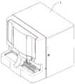
图1是一种具备自动进样功能的样本分析仪,该样本分析仪1包含用于在采样位置吸移样本的采样装置12和用于在吸移样本之前在混匀位置夹取并搬运样本容器以混匀样本的搬运装置11,如图2所示。FIG. 1 is a sample analyzer with automatic sample injection function, the
其中,搬运装置11与样本分析仪1的混匀位置对应设置,采样装置12与样本分析仪1的采样位置对应设置。The conveying
样本分析仪1所涉及的一种样本架如图3所示,样本架80设有若干用于固定样本容器90的样本容器固定孔801。样本分析仪1的搬运装置11从途径样本分析仪1的混匀位置的样本架80的样本容器固定孔801中抓取样本容器90,以便对样本容器90中的样本进行混匀。样本分析仪1的采样装置12从途径样本分析仪1的采样位置的固定于样本架80的样本容器固定孔801中的样本容器90中吸移样本。A sample holder involved in the
应说明的是,样本分析仪1的采样位置与混匀位置的位置关系是与样本架80的样本容器固定孔801的位置关系对应的。比如样本架80的样本容器固定孔801a与801b相邻,样本容器固定孔801a与801c间隔1位(即间隔1个样本容器固定孔801b),样本容器固定孔801a与801d间隔2位(即间隔2个样本容器固定孔801b和801c),并且以此类推。相应地,当样本架80的样本容器固定孔801a运动到与样本分析仪1的采样位置对应时,此时样本架80的样本容器固定孔801b正好与样本分析仪1的混匀位置对应,则被定义为采样位置与混匀位置相邻;当样本架80的样本容器固定孔801a运动到与样本分析仪1的采样位置对应时,此时样本架80的样本容器固定孔801c正好与样本分析仪1的混匀位置对应,则被定义为采样位置与混匀位置间隔1位;当样本架80的样本容器固定孔801a运动到与样本分析仪1的采样位置对应时,此时样本架80的样本容器固定孔801d正好与样本分析仪1的混匀位置对应,则被定义为采样位置与混匀位置间隔2位;并且以此类推。It should be noted that the positional relationship between the sampling position and the mixing position of the
在没有特殊说明的情况下,采样位置与混匀位置相邻以及间隔均参照上述解释和说明。Unless otherwise specified, the sampling position and the mixing position are adjacent to and spaced from each other with reference to the above explanations and descriptions.
如图4至图6所示,图1和图2所示的样本分析仪1的搬运装置11可以包括:夹爪1101、第一支撑架1111、第二支撑架1112、第三支撑架1113、电机1121~1123、竖直导轨1131~1132、绕在同步轮上的环形同步齿形带1141~1143以及转轴1151。其中电机1121~1123优选为步进电机。As shown in FIG. 4 to FIG. 6 , the handling
第一支撑架1111用于固定电机1121、竖直导轨1131,第一支撑架1111通过螺钉固定于样本分析仪1的前板(未示出)。竖直导轨1131沿Z1和Z2方向设置,第二支撑架1112与竖直导轨1131的滑块连接以能沿Z1或Z2方向滑动。第二支撑架1112用于固定电机1122和竖直导轨1132,竖直导轨1132沿Y1和Y2方向设置,第三支撑架1113与竖直导轨1132的滑块连接以能沿Y1或Y2方向滑动。第三支撑架1113用于固定电机1123,并且转轴1151以转动连接方式固定在第三支撑架1113上,转轴1151可沿R1或R2方向转动,在该情况下,搬运装置11的夹爪1101在夹取样本容器之后在固定电机1123的驱动下能够转动,从而对样本容器中的样本、尤其是静脉血样本进行混匀。夹爪1101与转轴1151固定连接并且可跟随转轴1151沿R1或R2方向转动。其中,Z1-Z2方向为垂直于水平面的竖直方向,Y1-Y2方向为垂直于竖直方向的水平方向。The
环形同步齿形带1141受电机1121的旋转驱动,在两个同步轮的引导下转动。第二支撑架1112与环形同步齿形带1141连接,在电机1121驱动下,第二支撑架1112可带动夹爪1101沿Z1或Z2方向移动。The endless synchronous
环形同步齿形带1142受电机1122的旋转驱动,在两个同步轮的引导下转动。第三支撑架1113与环形同步齿形带1142连接,在电机1122驱动下,第三支撑架1113可带动夹爪1101沿Y1或Y2方向移动。The endless synchronous
环形同步齿形带1143受电机1123的旋转驱动,在两个同步轮的引导下转动。转轴1151在在电机1123驱动下,带动夹爪1101沿R1或R2方向转动。The endless synchronous
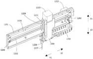
如图7和图8所示,图1和图2所示的样本分析仪1的采样装置12可以包括:水平支架1201,电机1202及1222,同步轮1203及1204,绕在同步轮1203及1204上的环形同步齿形带1205,沿Y1和Y2方向设置的水平导杆1206;竖直支架1221,沿Z1和Z2方向设置的竖直导杆1223,与竖直导杆1223平行设置的丝杠1224,套设在丝杠1224上的螺母1225,采样针固定部件1226,采样针1227,采样针清洗拭子1228,采样针连接管路1229,采样针连接管路固定件1330,坦克链1231。其中电机1202及1222优选为步进电机。As shown in FIGS. 7 and 8 , the
水平支架1201用于固定电机1202和水平导杆1206。竖直支架1221用于固定电机1222和竖直导杆1223。竖直支架1221套设在水平导杆1206上,并通过连接件与环形同步齿形带1205连接。环形同步齿形带1205受电机1202旋转驱动,在两个同步轮1203及1204的引导下转动。竖直支架1221可以在电机1202的驱动下沿Y1或Y2方向移动。The
采样针1227固定在采样针固定部件1226上,采样针固定部件1226套设在竖直导杆1223和丝杠1224上,并且螺母1225卡接在采样针固定部件1226设置的卡槽中,并且螺母1225和采样针固定部件1226之间不产生相对转动。丝杠1224通过螺钉与电机1222转轴连接,电机1222可以带动丝杠1224转动,并驱动采样针固定部件1226带着采样针1227沿Z1或Z2方向移动。The
采样针清洗拭子1228卡接在竖直支架1221上,采样针1227从采样针清洗拭子1228中部通孔穿过。当电机1222驱动采样针固定部件1226带着采样针1227沿Z1或Z2方向移动时,采样针1227相对采样针清洗拭子1228相对移动。采样针清洗拭子1228用于清洗采样针1227在从样本容器中吸样完成后残留在采样针1227外壁上的样本。The sampling
如图8所示,采样针连接管路1229与采样针1227连接,被采样针1227吸移的样本沿采样针连接管路1229运输。采样针连接管路固定件1330与竖直支架1221固定连接,用于固定采样针连接管路1229。坦克链1231用于铺设采样针连接管路1229以及电机1222的连接线。As shown in FIG. 8 , the sampling
搬运装置11与采样装置12在样本分析仪1上的相对位置关系如图9至图11所示。该样本分析仪1将混匀位置P1和采样位置P2设置成相邻,如图12所示。The relative positional relationship between the conveying
样本分析仪1的这种采样装置12和搬运装置11的结构和布局存在着固有缺陷:从图10的俯视图和图11的前视图可以看出,搬运装置11和采样装置12的运动机构在空间上存在部分重叠区域,当采样装置12的采样针1227位于A区域时,搬运装置11的夹爪1101沿Z1、Z2方向运动才是安全的;当采样装置12的采样针1227位于B区域时,搬运装置11的夹爪1101沿Z1、Z2方向运动就会与采样装置12发生干涉。为了不发生干涉,夹爪1101必须等到采样针1227返回到A区域后才可以动作,这就使得采样针1227的动作和夹爪1101的动作要部分串行进行。The structure and layout of the
假定样本的混匀需要耗时T1,采样针1227在图10的B区域进行采样、分样或吸移试剂时停留的时间为T2,样本往前进给1位的耗时为T3,样本到达采样位置P2到最终仪器输出其测量结果的时间为T4。Assuming that the mixing of the sample takes time T1, the time that the
参考图12和图13进行说明,当样本A到达采样位置P2时,样本B同时到达混匀位置P1。采样装置12对样本A进行采样和分样,在采样针1227在图10的B区域逗留的T2时间段内,夹爪1101都不能对样本B进行混匀。只有等采样针1227运动到图10的A区域后,夹爪1101才可以启动对样本B的混匀并耗时T1,混匀完成后进样器将样本B运输到采样位置P2并耗时T3,与此同时样本C到达混匀位置P1。此后,采样装置12对样本B进行采样和分样。类似的,在采样针1227在图10的B区域逗留的T2时间段内,夹爪1101都不能对样本C进行混匀。12 and 13 , when the sample A reaches the sampling position P2, the sample B simultaneously reaches the mixing position P1. The
在进行样本批量测试时,考虑到测量叠加,该分析仪的最高检测测试速度为:When performing batch testing of samples, taking into account the measurement overlay, the analyzer's maximum detection test speed is:

上述公式中,T1~T3的单位为s。In the above formula, the units of T1 to T3 are s.
其中,图13所示的A_T1、B_T1、C_T1、D_T1分别为样本A、B、C、D的混匀时间,A_T2、B_T2、C_T2、D_T2分别为样本A、B、C、D的采样时间,A_T3、B_T3、C_T3、D_T3分别为样本A、B、C、D前进一位的时间,A_T4、B_T4、C_T4、D_T4分别为样本A、B、C、D的检测时间。Among them, A_T1, B_T1, C_T1, D_T1 shown in Figure 13 are the mixing times of samples A, B, C, and D, respectively, A_T2, B_T2, C_T2, D_T2 are the sampling times of samples A, B, C, and D, respectively, A_T3, B_T3, C_T3, and D_T3 are the time for samples A, B, C, and D to advance one bit, respectively, and A_T4, B_T4, C_T4, and D_T4 are the detection times of samples A, B, C, and D, respectively.
可见,由于采样针1227的动作和夹爪1101的动作要部分串行进行,采样针1227在图10的B区域逗留的T2时间成了制约分析仪测量速度的一个因素。It can be seen that since the action of the
为了解决上述问题,本发明提供了一种样本分析仪,如图15至18所示,所述样本分析仪包括:In order to solve the above problems, the present invention provides a sample analyzer, as shown in FIGS. 15 to 18 , the sample analyzer includes:
样本架80,所述样本架80包括多个样本容器固定孔801,以用于容纳可装载样本的样本容器90;a
搬运装置11,所述搬运装置11构造成能沿竖直方向Z运动,以便将所述样本架80上处于混匀位置P1的样本容器90从其样本容器固定孔801中搬运出来用于混匀以及在混匀后搬运回到其样本容器固定孔801中;The handling
采样装置22,所述采样装置22具有采样针2227,所述采样针构造成能沿所述竖直方向Z运动伸入到所述样本架80上处于采样位置P2的样本容器固定孔801中,以便吸取该样本容器中的样本;The
检测装置(未示出),所述检测装置构造用于对由所述采样装置22所吸取的样本进行检测;a detection device (not shown) configured to detect the sample drawn by the
运样装置(未示出),所述运样装置构造用于运送所述样本架80,以便使所述样本架80上的样本容器90能依次经过所述混匀位置P1和所述采样位置P2;A sample transport device (not shown) configured to transport the
其中,所述搬运装置11和所述采样装置22相邻且间隔设置,使得所述采样装置22不干涉所述搬运装置11沿竖直方向Z的运动。Wherein, the conveying
本发明的所述样本分析仪由于所述搬运装置11和所述采样装置22相邻且间隔设置,不会在竖直方向的空间上发生重叠,因此能同时分别对所述样本架上处于所述混匀位置P1和所述采样位置P2的相应样本容器进行搬运和采样运送。In the sample analyzer of the present invention, since the conveying
可选地,所述搬运装置11和所述采样针2227构造成能沿垂直于所述竖直方向的第一方向Y水平来回运动,所述搬运装置11和所述采样装置22相邻且间隔设置,使得所述搬运装置11和所述采样针2227能互不干涉地沿所述第一方向Y水平来回运动。Optionally, the carrying
此外,所述搬运装置11和所述采样装置22沿垂直于所述竖直方向Z和所述第一方向Y的第二方向X间隔设置。In addition, the conveying
其中,按照本发明的样本分析仪的工作过程可以为:首先由运样装置(未示出)将样本架80上的相应的样本容器90运送至所述样本分析仪中设置的混匀位置P1和采样位置P2,在此例如将样本容器固定孔801b中的样本容器运送至采样位置P2,此时样本容器固定孔801c中的样本容器处于混匀位置P1。然后,采样装置22带动采样针2227先沿第一方向Y1水平移动至采样位置P2对应的样本容器的上方,然后采样针2227沿竖直方向Z2向下移动进入装载有待采样样本的样本容器中并吸取所述待采样样本,在吸取待采样样本之后,采样针2227沿竖直方向Z1上升离开该样本容器,然后采样装置22带动采样针2227沿第一方向Y2水平移动至检测装置并将吸取的待采样样本排出到检测装置中以对所述样本进行检测。在采样装置22对处于采样位置P2对应的样本容器进行采样作业的同时,搬运装置11将样本架80上处于混匀位置P1的样本容器固定孔801c中的样本容器搬运出来进行混匀作业。例如,在搬运过程中,搬运装置11的高度与处于混匀位置P1的样本容器相对应,搬运装置11沿第一方向Y1水平移动直至接触相应的样本容器,依靠搬运装置11前进的作用力使所述样本容器挤进所述搬运装置11中,从而搬运装置11夹取所述样本容器,接着搬运装置11带着其夹取的样本容器沿竖直方向Z1向上移动离开样本架并对所述样本容器进行摇动混匀或者将所述样本容器搬运到另外的混匀装置中进行混匀。当采样装置22对样本容器固定孔801b中的样本容器的采样作业以及搬运装置11对样本容器固定孔801c中的样本容器的混匀作业结束之后,由运样装置(未示出)将样本架80移动一个样本容器固定孔的距离,使得样本容器固定孔801c中的样本容器运送至采样位置P2,此时样本容器固定孔801d中的样本容器处于混匀位置P1,接着由采样装置22和搬运装置11同时分别对样本容器固定孔801c中的样本容器进行采样作业和对样本容器固定孔801d中的样本容器进行混匀作业,直至样本架80上的所有样本容器完成检测。Wherein, the working process of the sample analyzer according to the present invention may be as follows: first, the
下面结合附图14至18对本发明所述样本分析仪做进一步的说明。The sample analyzer of the present invention will be further described below with reference to FIGS. 14 to 18 .
需要说明的是,在本发明中,所述竖直方向为垂直于水平面的方向,为上下方向,例如Z方向,如图15、图16和图18所示的方向Z1、Z2。所述第一方向是指在水平面上所述采样装置在采样位置和检测装置之间运行轨迹的方向或者说在水平方向上与被运送至样本分析仪的样本架的延伸方向相垂直的方向,为前后方向,例如Y方向,如图15至图17所示的Y1、Y2方向;所述第二方向是指水平面上与所述垂直方向和所述第一方向相垂直的方向,与被运送至样本分析仪的样本架的延伸方向平行,为左右方向,例如X方向,如图17和图18所示的X1、X2方向。It should be noted that, in the present invention, the vertical direction is the direction perpendicular to the horizontal plane, which is the up-down direction, such as the Z direction, such as the directions Z1 and Z2 shown in FIG. 15 , FIG. 16 and FIG. 18 . The first direction refers to the direction of the running track of the sampling device between the sampling position and the detection device on the horizontal plane, or the direction in the horizontal direction is perpendicular to the extending direction of the sample rack that is transported to the sample analyzer, It is the front and rear direction, such as the Y direction, such as the Y1 and Y2 directions shown in Figure 15 to Figure 17; the second direction refers to the direction on the horizontal plane that is perpendicular to the vertical direction and the first direction, and is transported. The extending direction to the sample holder of the sample analyzer is parallel, and is the left-right direction, for example, the X direction, such as the X1 and X2 directions shown in FIGS. 17 and 18 .
在本发明的一示例中,所述采样装置22与所述采样位置P2对应设置,所述搬运装置11与所述混匀位置P1对应设置。In an example of the present invention, the
在本发明的一示例中,在所述样本分析仪中,所述混匀位置P1和所述采样位置P2不再相邻设置,而是间隔至少一个样本容器固定孔的距离,使得所述搬运装置和所述采样装置在第二方向、即X方向上的距离增大,以保证所述搬运装置和所述采样装置在Z方向上运动时不会发生如图10和图11所示的干涉,从而搬运装置和采样装置能同时分别对样本架上处于混匀位置和采样位置的间隔至少一个样本容器固定孔的样本容器进行搬运和采样。In an example of the present invention, in the sample analyzer, the mixing position P1 and the sampling position P2 are no longer adjacent to each other, but are separated by a distance of at least one sample container fixing hole, so that the handling The distance between the device and the sampling device in the second direction, that is, the X direction is increased to ensure that the transport device and the sampling device do not interfere in the Z direction when they move in the Z direction. Therefore, the carrying device and the sampling device can simultaneously carry and sample the sample containers in the mixing position and the sampling position spaced by at least one sample container fixing hole on the sample rack, respectively.
在一具体的实施例中,所述样本分析仪的搬运装置11和采样装置22的相关结构均可以参照关于附图1至图11的解释和说明,在此不再赘述。In a specific embodiment, the related structures of the handling
在一个示例中,如图14所示,将混匀位置P1和采样位置P2设置为间隔一个样本容器固定孔的距离,从而使搬运装置和采样装置在Z方向上独立运行而不干涉。In one example, as shown in FIG. 14 , the mixing position P1 and the sampling position P2 are set at a distance of one sample container fixing hole, so that the conveying device and the sampling device operate independently in the Z direction without interference.
需要说明的是,通过将混匀位置和采样位置间隔设置之后,搬运装置和采样装置不仅在竖直方向即Z方向上互不干涉,其在水平面的X方向和Y方向上也互不干涉,在本发明的实施例中,在不做相反的解释和说明的情况下,搬运装置和采样装置在X方向和Y方向上均不发生干涉,即沿X方向和Y方向,搬运装置和采样装置在空间上不会发生重叠。It should be noted that, by setting the mixing position and the sampling position at intervals, the conveying device and the sampling device not only do not interfere with each other in the vertical direction, that is, the Z direction, but also do not interfere with each other in the X and Y directions of the horizontal plane. In the embodiment of the present invention, in the case of no explanation and description to the contrary, the conveying device and the sampling device do not interfere in the X direction and the Y direction, that is, along the X direction and the Y direction, the conveying device and the sampling device do not interfere There will be no overlap in space.
下面结合附图14对本发明的样本分析仪做详细的说明。如图14所示,在将样本分析仪的混匀位置P1和采样位置P2设计成不相邻,比如间隔1位之后,当样本A到达采样位置P2时,样本C到达混匀位置P1,样本B位于采样位置P2和混匀位置P1之间,并且样本B已经混匀。The sample analyzer of the present invention will be described in detail below with reference to FIG. 14 . As shown in Figure 14, after designing the mixing position P1 and the sampling position P2 of the sample analyzer to be non-adjacent, for example, after the interval is 1 bit, when the sample A reaches the sampling position P2, the sample C reaches the mixing position P1, and the sample B is located between sampling position P2 and mixing position P1, and sample B has been mixed.
由于混匀位置P1和采样位置P2不相邻,采样装置22和搬运装置11的运动机构不会发生干涉,例如采样针2227的动作和夹爪1101的动作可以相互独立。Since the mixing position P1 and the sampling position P2 are not adjacent, the movement mechanisms of the
当采样针2227在对样本A进行采样时,夹爪1101可以同时对样本C进行混匀。一般情况下,采样针的采样耗时要小于或等于夹爪的混匀耗时。当样本C完成混匀时,样本A已完成采样,此时进样器(即运样装置)可以将样本B送达采样位置P2。此时从采样针2227对样本A进行采集到采样针对样本B进行采集的最短时间间隔为T1+T3,那么该分析仪的最高检测速度可达到:When the

在该实施例中,在样本架放满样本情况下,样本B从在混匀位置P1完成混匀到运动到采样位置P2的时间间隔为T1+2×T3,其中T1是样本B在位于采样位置P2和混匀位置P1之间等待混匀位置P1的样本C完成混匀的耗时,2×T3是样本B从混匀位置P1进给2次到达采样位置P2的耗时。样本B混匀后经过了T1+2×T3才能被采集,在T1+2×T3时间,样本B中的血细胞有重新沉降的风险。若T1+2×T3的时间偏长,则会影响测量结果,若T1+2×T3时间够短,则对结果的影响不大。在该情况下可以通过合理设计T1和T3,使得完成混匀的并且等待采样的样本尽可能不会发生重新沉降的风险。In this embodiment, when the sample rack is full of samples, the time interval from the completion of mixing of the sample B at the mixing position P1 to the movement to the sampling position P2 is T1+2×T3, where T1 is the time when the sample B is at the sampling position P2. Between the position P2 and the mixing position P1, waiting for the sample C at the mixing position P1 to complete the mixing, 2×T3 is the time it takes for the sample B to be fed twice from the mixing position P1 to the sampling position P2. Sample B can be collected only after T1+2×T3 after mixing. At T1+2×T3, the blood cells in sample B are at risk of re-settling. If the time of T1+2×T3 is too long, it will affect the measurement result. If the time of T1+2×T3 is short enough, it will have little effect on the result. In this case, T1 and T3 can be reasonably designed so that the samples that have been mixed and are waiting to be sampled do not have the risk of re-settling as much as possible.
当然,在本发明的另一实施例中,也可以将所述混匀位置P1和所述采样位置P2设计成相邻的。在该实施例中,对所述样本分析仪的结构进行了进一步的改进,其中,在上述实施例中对所述样本分析仪的各种结构、设置以及相关的解释和说明在与本实施例不相互矛盾的情况下,可以将其引入该实施例中。Of course, in another embodiment of the present invention, the mixing position P1 and the sampling position P2 can also be designed to be adjacent. In this embodiment, the structure of the sample analyzer is further improved, wherein the various structures, settings, and related explanations and descriptions of the sample analyzer in the above-mentioned embodiment are not related to this embodiment. They may be incorporated into this embodiment without being inconsistent with each other.
从图10的俯视图和图11的前视图可以看出,与搬运装置11、尤其是夹爪1101沿Z1方向运动发生干涉的零部件包括:采样装置12的电机1222、竖直支架1221、采样针连接管路1229、采样针连接管路固定件1330以及坦克链1231。It can be seen from the top view of FIG. 10 and the front view of FIG. 11 that the components that interfere with the movement of the conveying
下面对结合附图15至18对改进后的样本分析仪进行详细的说明,尤其是对所述采样装置和搬运装置进行说明。The improved sample analyzer will be described in detail below with reference to FIGS. 15 to 18 , especially the sampling device and the conveying device.
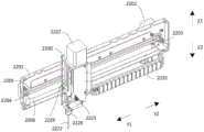
其中,如图15和图16所示,所述采样装置22包括:沿所述第一方向即Y1-Y2方向设置的水平支架2201和沿竖直方向即Z1-Z2方向设置的竖直支架2221。其中,所述竖直支架2221可沿所述第一方向即Y1-Y2方向运动地设置在所述水平支架2201上,以使所述竖直支架2221在所述水平支架上沿所述第一方向即Y1-Y2方向往返运动,以实现取样和将取样排出至检测装置中用于进行分析。Wherein, as shown in FIGS. 15 and 16 , the
可选地,所述竖直支架2221设置于靠近所述搬运装置11的一侧并且构造使得所述竖直支架2221不干涉所述搬运装置11沿竖直方向Z1-Z2的运动,如图17所示,所述竖直支架2221与所述搬运装置11相邻设置。Optionally, the
其中,采样装置22还可以包括沿所述第一方向即Y1-Y2方向设置的水平导杆2206,其中,所述水平导杆2206可以设置于所述水平支架2201的中下部,例如设置于水平支架2201的底部,如图15所示。所述水平导杆2206的两端分别固定于所述水平支架2201的两端。所述竖直支架2221可沿所述第一方向运动地套设在所述水平导杆上。Wherein, the
可选地,所述采样装置22还包括第一驱动组件2202,用于驱动所述竖直支架2221连同设置于其上的所述采样针2227沿水平导杆2206运动,其中,所述第一驱动组件2202固定于所述水平支架上,例如固定于所述水平支架2201的背离所竖直支架2221的一侧上并且位于所述水平支架2201上远离采样位置P2的一端上,如图15所示。Optionally, the
其中,所述第一驱动组件2202包括电机,例如步进电机等,但并不局限于该示例。Wherein, the
应说明的是,采样装置22的水平驱动机构的各个部件2201至2206与上述采样装置12的水平驱动机构的各个部件1201至1206的结构基本相同,在此不再赘述。It should be noted that the
进一步,所述采样装置22还包括沿竖直方向即Z1-Z2方向设置的竖直导轨2223、与竖直导轨2223平行设置的丝杠2224以及套设在丝杠2224上的螺母2225。其中,所述竖直导轨2223固定设置于所述竖直支架上。Further, the
其中,所述采样针2227设置在所述竖直支架2221上,以使所述竖直支架2221能带动所述采样针2227沿所述第一方向运动,所述竖直支架构造使得所述竖直支架不干涉所述搬运装置沿竖直方向的运动。Wherein, the
具体地,所述采样装置22还包括采样针固定部件2226、采样针清洗拭子2228、采样针连接管路2229、采样针连接管路固定件1330以及收纳部2231。Specifically, the
其中,所述采样针2227固定在采样针固定部件2226上,采样针固定部件2226固定在竖直导轨2223的滑块上,丝杠2224从采样针固定部件2226设置的孔中穿过,并且螺母2225卡接在采样针固定部件2226设置的卡槽中,并且螺母2225和采样针固定部件2226之间不产生相对转动。The
所述采样装置22还包括第二驱动组件2222,固定于所述竖直支架上,其中,所述丝杠2224通过螺钉与第二驱动组件2222转轴连接,第二驱动组件2222可以带动丝杠2224转动,并驱动采样针固定部件2226带着采样针2227沿Z1或Z2方向移动。The
所述第二驱动组件2222设置在所述竖直支架2221上方并且靠近所述水平支架2201,使得其不干涉所述搬运装置21沿竖直方向的运动。所述第二驱动组件2222包括电机,例如步进电机等,但并不局限于该示例。The
在一示例中,通过减小所述第二驱动组件2222的尺寸,以使所述第二驱动组件2222与搬运装置11不发生干涉,例如在沿X、Y和Z方向上均不会发生重叠。其中,可以通过减小所述第二驱动组件2222在X方向上的尺寸,或者将所述第二驱动组件2222在X方向上向远离所述搬运装置21的方向移动,从而使所述搬运装置11和第二驱动组件2222间隔设置,在运行时不会发生干涉。In one example, by reducing the size of the
进一步,采样针清洗拭子2228固定在竖直支架2221上,采样针2227从采样针清洗拭子2228中部通孔穿过。所述采样针沿竖直方向移动时,所述采样针相对所述采样针清洗拭子相对移动。Further, the sampling
如图16所示,采样针连接管路2229一端与采样针2227连接,采样针连接管路2229另一端连接压力源(未示出),采样针连接管路2229可以用于为所述采样针2227提供压力,即:当采样针2227进行吸样作业时,采样针连接管路2229为所述采样针2227提供负压,以便采样针吸取样本;当采样针2227沿Y2方向运动到检测装置的反应池之后,采样针连接管路2229为所述采样针2227提供正压,采样针2227在正压作用下排出样本,当然也可以直接由采样针连接管路2229在负压的作用下直接将样本从采样针抽吸到检测装置的反应池中。采样针连接管路固定件2330与竖直支架2221固定连接,用于固定采样针连接管路2229。As shown in FIG. 16 , one end of the sampling
其中,所述采样针连接管路2229和所述采样针连接管路固定件2330被布置使得其不干涉所述搬运装置沿竖直方向的运动。Wherein, the sampling
具体地,在一示例中,所述样本分析仪的混匀位置P1和采样位置P2相邻,则采样装置22的采样针2227相对搬运装置11的夹爪1101的间距与图10和图11所示的采样装置12的采样针1227相对搬运装置11的夹爪1101的间距相同,为了避免采样装置22与搬运装置11发生干涉,需要改变采样针连接管路2229的位置,即,将采样针连接管路2229设置于竖直支架2221中远离所述搬运装置11的一侧,如图16所示。Specifically, in an example, the mixing position P1 of the sample analyzer is adjacent to the sampling position P2, and the distance between the
同样地,可以改变采样针连接管路固定件2330的位置,将连接管路固定件2330设置于所述竖直支架2221中远离所述搬运装置11的一侧,如图16所示。Similarly, the position of the connecting
通过将采样针连接管路2229和连接管路固定件2330转移至竖直支架中远离搬运装置的一侧,增加了采样装置22和搬运装置11之间的间距,避免了在竖直方向上发生重叠或干涉。By transferring the sampling
此外,除了移动采样针连接管路2229和连接管路固定件2330之外,还可以通过减小采样针连接管路2229和连接管路固定件2330的尺寸,或者在移动采样针连接管路2229和连接管路固定件2330的同时减小采样针连接管路2229和连接管路固定件2330的尺寸,以实现上述效果。In addition, in addition to moving the sampling
进一步,收纳部2231用于收纳采样针连接管路2229和收纳采样装置22的线缆,例如用于铺设采样针连接管路2229以及第二驱动组件2222的连接线。其中,收纳部与竖直支架固定连接并且设置在水平支架2201的下方,使得其不干涉所述搬运装置沿竖直方向的运动。Further, the
具体地,为了防止收纳部2231对搬运装置造成干涉,减小收纳部2231和水平支架之间的距离,例如使收纳部与搬运装置之间的X方向距离大于竖直支架与搬运装置之间的X方向距离,从而使收纳部2231不会向搬运装置的一侧凸出对搬运装置造成干涉。Specifically, in order to prevent the
在本发明的一示例中,将收纳部2231构造为一端固定且另一端能随着竖直支架沿所述第一方向移动的坦克链。In an example of the present invention, the receiving
可选地,坦克链设置为与水平支架大致相互平行,坦克链的一端固定在水平支架2201上并且另一端与竖直支架2221连接,从而能随着所述竖直支架2221沿第一方向Y1-Y2运动。Optionally, the tank chain is arranged substantially parallel to the horizontal support, one end of the tank chain is fixed on the
在本发明中通过对采样装置中的一些部件进行缩小和/或位置移动之后,从图17的俯视图和图18的前视图可以看出,搬运装置11和采样装置22的运动机构在空间上不存在重叠区域,搬运装置11的夹爪1101与采样装置22之间在X1、X2方向上保持着间距d,使得搬运装置11的夹爪1101和采样装置22的采样针2227的动作可以相互独立。In the present invention, after some parts in the sampling device are reduced and/or moved in position, it can be seen from the top view of FIG. 17 and the front view of FIG. There is an overlapping area, and a distance d is maintained between the
换言之,当样本A到达采样位置P2时,样本B同时到达混匀位置P1。当采样针2227在对样本A进行采样时,夹爪1101可以同时对样本B进行混匀。一般情况下,采样针的采样耗时要小于等于夹爪的混匀耗时。当样本B完成混匀时,样本A已完成采样,此时进样器可以将样本B送达采样位置P2。那么从采样针2227对样本A进行采集到采样针对样本B进行采集的最短时间间隔为T1+T3,那么该样本分析仪的最高检测速度可达到:In other words, when the sample A reaches the sampling position P2, the sample B simultaneously reaches the mixing position P1. When the

通过上述改进,所述样本分析仪解决了采样装置和搬运装置相互干涉的问题,使得采样针和夹爪动作可以并行进行,消除样本B等待样本A采样后才能进行混匀的时间T2,因此按照本发明的样本分析仪的这种采样装置和搬运装置的结构和布局可以使该样本分析仪获得较高的检测速度。Through the above improvements, the sample analyzer solves the problem of mutual interference between the sampling device and the conveying device, so that the actions of the sampling needle and the gripper can be performed in parallel, eliminating the time T2 for the sample B to wait for the sample A to be sampled before it can be mixed. The structure and layout of the sampling device and the carrying device of the sample analyzer of the present invention can enable the sample analyzer to obtain a higher detection speed.
应说明的是,按照本发明的搬运装置与上述搬运装置11的结构基本相同,在此不再赘述。It should be noted that the structure of the conveying device according to the present invention is basically the same as that of the above-mentioned conveying
此外,在另外一个示例中,所述样本分析仪包括混匀装置(未示出),所述搬运装置能将所述样本架上处于混匀位置的样本容器从其样本容器固定孔中搬运出来放置到所述混匀装置中,以对该样本容器中的样本进行混匀。优选地,所述混匀装置可以对末梢血样本进行混匀,而所述搬运装置不仅可以用于搬运样本容器,还可以对静脉血样本进行混匀。In addition, in another example, the sample analyzer includes a mixing device (not shown), and the carrying device can carry the sample container in the mixing position on the sample rack out of the sample container fixing hole thereof. into the mixing device to mix the sample in the sample container. Preferably, the mixing device can mix the peripheral blood samples, and the handling device can not only be used for handling the sample container, but also can mix the venous blood samples.
可选地,所述检测装置包括细胞分类计数模块(未示出)和CRP检测模块(未示出),所述细胞分类计数模块用于对由所述采样装置所吸取的样本中的粒子进行分类和计数,所述CRP检测模块用于检测由所述采样装置所吸取的样本的CRP浓度。Optionally, the detection device includes a cell sorting and counting module (not shown) and a CRP detection module (not shown), and the cell sorting and counting module is used to perform particle analysis on the particles in the sample drawn by the sampling device. Sorting and counting, the CRP detection module is used to detect the CRP concentration of the sample drawn by the sampling device.
其中,所述CRP检测模块可以包括:Wherein, the CRP detection module can include:
反应池,设置用于提供样本和试剂的反应场所;Reaction pool, set up a reaction place for providing samples and reagents;
光度计,设置用于对样本中的分析物进行光照射,以便获得分析物在不同时间段下的吸光度。A photometer configured to illuminate the analyte in the sample with light in order to obtain the absorbance of the analyte over different time periods.
根据本发明的实施例所述样本分析仪中,所述搬运装置构造成能沿竖直方向运动,所述采样装置具有采样针,所述采样针构造成能沿所述竖直方向运动伸入到所述样本架上处于采样位置的样本容器中,并且所述搬运装置和所述采样装置相邻且间隔设置,使得所述采样装置不干涉所述搬运装置沿竖直方向的运动,通过所述改进可提高样本分析仪的检测速度。In the sample analyzer according to an embodiment of the present invention, the carrying device is configured to be movable in a vertical direction, the sampling device has a sampling needle, and the sampling needle is configured to be movable in the vertical direction to extend into into the sample container in the sampling position on the sample rack, and the conveying device and the sampling device are adjacent and spaced apart, so that the sampling device does not interfere with the movement of the conveying device in the vertical direction. These improvements can increase the detection speed of the sample analyzer.
本发明实施例中所使用的技术术语仅用于说明特定实施例而并不旨在限定本发明。在本文中,单数形式“一”、“该”及“所述”用于同时包括复数形式,除非上下文中明确另行说明。进一步地,在说明书中所使用的用于“包括”和/或“包含”是指存在所述特征、整体、步骤、操作、元件和/或构件,但是并不排除存在或增加一个或多个其它特征、整体、步骤、操作、元件和/或构件。The technical terms used in the embodiments of the present invention are only used to describe specific embodiments and are not intended to limit the present invention. As used herein, the singular forms "a," "the," and "the" are used to include the plural forms as well, unless the context clearly dictates otherwise. Further, as used in the specification for "comprising" and/or "comprising" refers to the presence of the stated features, integers, steps, operations, elements and/or components, but does not preclude the presence or addition of one or more Other features, integers, steps, operations, elements and/or components.
在所附权利要求中对应结构、材料、动作以及所有装置或者步骤以及功能元件的等同形式(如果存在的话)旨在包括结合其他明确要求的元件用于执行该功能的任何结构、材料或动作。本发明的描述出于实施例和描述的目的被给出,但并不旨在是穷举的或者将被本发明限制在所公开的形式。在不偏离本发明的范围和精神的情况下,多种修改和变形对于本领域的一般技术人员而言是显而易见的。本发明中所描述的实施例能够更好地揭示本发明的原理与实际应用,并使本领域的一般技术人员可了解本发明。The corresponding structures, materials, acts, and equivalents of all means or step and function elements, if any, in the appended claims are intended to include any structure, material, or act for performing the function in combination with other explicitly claimed elements. The description of the present invention has been presented for purposes of example and description, but is not intended to be exhaustive or to limit the invention to the form disclosed. Various modifications and variations will be apparent to those skilled in the art without departing from the scope and spirit of the invention. The embodiments described in the present invention can better disclose the principles and practical applications of the present invention, and enable those skilled in the art to understand the present invention.
本发明中所描述的流程图仅仅为一个实施例,在不偏离本发明的精神的情况下对此图示或者本发明中的步骤可以有多种修改变化。比如,可以不同次序的执行这些步骤,或者可以增加、删除或者修改某些步骤。本领域的一般技术人员可以理解实现上述实施例的全部或部分流程,并依本发明权利要求所作的等同变化,仍属于本发明所涵盖的范围。The flowchart described in the present invention is only an embodiment, and various modifications and changes may be made to this illustration or the steps in the present invention without departing from the spirit of the present invention. For example, the steps may be performed in a different order, or certain steps may be added, deleted, or modified. Those skilled in the art can understand that all or part of the flow of the above-mentioned embodiments, and the equivalent changes made according to the claims of the present invention, still belong to the scope covered by the present invention.
Claims (16)
Translated fromChinesePriority Applications (1)
| Application Number | Priority Date | Filing Date | Title |
|---|---|---|---|
| CN201910528547.1ACN112098671A (en) | 2019-06-18 | 2019-06-18 | Sample analyzer |
Applications Claiming Priority (1)
| Application Number | Priority Date | Filing Date | Title |
|---|---|---|---|
| CN201910528547.1ACN112098671A (en) | 2019-06-18 | 2019-06-18 | Sample analyzer |
Publications (1)
| Publication Number | Publication Date |
|---|---|
| CN112098671Atrue CN112098671A (en) | 2020-12-18 |
Family
ID=73748735
Family Applications (1)
| Application Number | Title | Priority Date | Filing Date |
|---|---|---|---|
| CN201910528547.1APendingCN112098671A (en) | 2019-06-18 | 2019-06-18 | Sample analyzer |
Country Status (1)
| Country | Link |
|---|---|
| CN (1) | CN112098671A (en) |
Cited By (4)
| Publication number | Priority date | Publication date | Assignee | Title |
|---|---|---|---|---|
| CN115480067A (en)* | 2021-05-31 | 2022-12-16 | 深圳市帝迈生物技术有限公司 | Sample analyzer and sample detection method |
| CN115541904A (en)* | 2021-06-30 | 2022-12-30 | 深圳市瑞图生物技术有限公司 | A sample analyzer |
| CN115541909A (en)* | 2021-06-30 | 2022-12-30 | 深圳市瑞图生物技术有限公司 | A kind of transmission device and sample analyzer |
| CN116609535A (en)* | 2023-05-17 | 2023-08-18 | 中元汇吉生物技术股份有限公司 | Sample analysis and sample injection control method |
Citations (9)
| Publication number | Priority date | Publication date | Assignee | Title |
|---|---|---|---|---|
| AT1571U1 (en)* | 1996-09-13 | 1997-07-25 | Avl Verbrennungskraft Messtech | ARRANGEMENT FOR SAMPLING |
| CN101603968A (en)* | 2009-07-14 | 2009-12-16 | 重庆天海医疗设备有限公司 | The closed automatic detection device of blood rheology measurement |
| CN103364577A (en)* | 2012-03-29 | 2013-10-23 | 深圳市开立科技有限公司 | Feeding and sampling device for hematology analyzer |
| WO2015165019A1 (en)* | 2014-04-28 | 2015-11-05 | 深圳迈瑞生物医疗电子股份有限公司 | Smear preparation device, smear preparation method and glass slide basket drying module |
| WO2016000216A1 (en)* | 2014-07-01 | 2016-01-07 | 深圳迈瑞生物医疗电子股份有限公司 | Whole blood sample testing method and blood tester |
| CN105628948A (en)* | 2016-03-04 | 2016-06-01 | 深圳普门科技有限公司 | High-speed C reactive protein analyzer and analyzing method thereof |
| WO2017081413A1 (en)* | 2015-11-13 | 2017-05-18 | Horiba Abx Sas | Device for agitating and collecting biological liquid samples suitable for sorting |
| WO2017128806A1 (en)* | 2016-01-27 | 2017-08-03 | 广州万孚生物技术股份有限公司 | Automatic fluorescence quantitative immunoassay analyzer and detection method |
| CN210401445U (en)* | 2019-06-18 | 2020-04-24 | 深圳迈瑞生物医疗电子股份有限公司 | Sample analyzer |
- 2019
- 2019-06-18CNCN201910528547.1Apatent/CN112098671A/enactivePending
Patent Citations (12)
| Publication number | Priority date | Publication date | Assignee | Title |
|---|---|---|---|---|
| AT1571U1 (en)* | 1996-09-13 | 1997-07-25 | Avl Verbrennungskraft Messtech | ARRANGEMENT FOR SAMPLING |
| CN101603968A (en)* | 2009-07-14 | 2009-12-16 | 重庆天海医疗设备有限公司 | The closed automatic detection device of blood rheology measurement |
| CN103364577A (en)* | 2012-03-29 | 2013-10-23 | 深圳市开立科技有限公司 | Feeding and sampling device for hematology analyzer |
| WO2015165019A1 (en)* | 2014-04-28 | 2015-11-05 | 深圳迈瑞生物医疗电子股份有限公司 | Smear preparation device, smear preparation method and glass slide basket drying module |
| WO2016000216A1 (en)* | 2014-07-01 | 2016-01-07 | 深圳迈瑞生物医疗电子股份有限公司 | Whole blood sample testing method and blood tester |
| CN105378478A (en)* | 2014-07-01 | 2016-03-02 | 深圳迈瑞生物医疗电子股份有限公司 | Whole blood sample detection method and blood detector |
| CN107656085A (en)* | 2014-07-01 | 2018-02-02 | 深圳迈瑞生物医疗电子股份有限公司 | A kind of blood detector |
| CN107656068A (en)* | 2014-07-01 | 2018-02-02 | 深圳迈瑞生物医疗电子股份有限公司 | A kind of blood detector |
| WO2017081413A1 (en)* | 2015-11-13 | 2017-05-18 | Horiba Abx Sas | Device for agitating and collecting biological liquid samples suitable for sorting |
| WO2017128806A1 (en)* | 2016-01-27 | 2017-08-03 | 广州万孚生物技术股份有限公司 | Automatic fluorescence quantitative immunoassay analyzer and detection method |
| CN105628948A (en)* | 2016-03-04 | 2016-06-01 | 深圳普门科技有限公司 | High-speed C reactive protein analyzer and analyzing method thereof |
| CN210401445U (en)* | 2019-06-18 | 2020-04-24 | 深圳迈瑞生物医疗电子股份有限公司 | Sample analyzer |
Cited By (4)
| Publication number | Priority date | Publication date | Assignee | Title |
|---|---|---|---|---|
| CN115480067A (en)* | 2021-05-31 | 2022-12-16 | 深圳市帝迈生物技术有限公司 | Sample analyzer and sample detection method |
| CN115541904A (en)* | 2021-06-30 | 2022-12-30 | 深圳市瑞图生物技术有限公司 | A sample analyzer |
| CN115541909A (en)* | 2021-06-30 | 2022-12-30 | 深圳市瑞图生物技术有限公司 | A kind of transmission device and sample analyzer |
| CN116609535A (en)* | 2023-05-17 | 2023-08-18 | 中元汇吉生物技术股份有限公司 | Sample analysis and sample injection control method |
Similar Documents
| Publication | Publication Date | Title |
|---|---|---|
| CN112098671A (en) | Sample analyzer | |
| CN210401445U (en) | Sample analyzer | |
| CN102539800B (en) | Sample analyzer and sample analyzing method | |
| CN207866714U (en) | Chemiluminescence detector | |
| CN111735978A (en) | Fully automatic chemiluminescence immunoassay analyzer | |
| CN110794154A (en) | Chemiluminescence immunity analyzer and detection method thereof | |
| CN109975277A (en) | Chemiluminescence detector and detection method thereof | |
| CN110873803B (en) | Fully automatic chemiluminescence analyzer | |
| JP2012132941A (en) | Specimen-transport module for multi-instrument clinical work cell | |
| CN204347046U (en) | A kind of full-automatic fluorescence immunoassay quantitative analysis device | |
| CN107121561B (en) | A fully automatic fluorescence immunoquantitative analysis equipment | |
| JP5342389B2 (en) | Specimen processing apparatus and specimen transport apparatus | |
| CN219245553U (en) | Full-automatic dry-type fluorescence immunoassay appearance | |
| CN110873804B (en) | Fully automatic chemiluminescence analyzer | |
| WO2015046425A1 (en) | Test piece pickup mechanism, test piece moving apparatus, liquid sample analytical apparatus, and test piece pickup method | |
| CN116047096A (en) | Automatic sample analyzer | |
| CN114544471B (en) | Sample analyzer and sample detection process thereof | |
| CN114660317A (en) | Flow type fluorescence luminescence immunoassay instrument | |
| CN106501538B (en) | A kind of reagent loading system | |
| CN118465291A (en) | Full-automatic high-speed immune luminescence analyzer | |
| CN102023110B (en) | Sample processing device, sample transporting device, and sample rack transporting method | |
| CN222318966U (en) | A fully automatic urine protein analysis and detection line | |
| CN112162105B (en) | High-speed magnetic washing incubation photometry device | |
| CN205594017U (en) | A fully automatic specific protein analyzer | |
| CN105866451B (en) | A fully automatic specific protein analyzer |
Legal Events
| Date | Code | Title | Description |
|---|---|---|---|
| PB01 | Publication | ||
| PB01 | Publication | ||
| SE01 | Entry into force of request for substantive examination | ||
| SE01 | Entry into force of request for substantive examination |