CN112096925A - A novel energy-saving gas stove regulating valve body device and outer ring fire control method - Google Patents
A novel energy-saving gas stove regulating valve body device and outer ring fire control methodDownload PDFInfo
- Publication number
- CN112096925A CN112096925ACN202010782237.5ACN202010782237ACN112096925ACN 112096925 ACN112096925 ACN 112096925ACN 202010782237 ACN202010782237 ACN 202010782237ACN 112096925 ACN112096925 ACN 112096925A
- Authority
- CN
- China
- Prior art keywords
- iron core
- coil
- valve
- outer ring
- ring fire
- Prior art date
- Legal status (The legal status is an assumption and is not a legal conclusion. Google has not performed a legal analysis and makes no representation as to the accuracy of the status listed.)
- Pending
Links
Images


Classifications
- F—MECHANICAL ENGINEERING; LIGHTING; HEATING; WEAPONS; BLASTING
- F16—ENGINEERING ELEMENTS AND UNITS; GENERAL MEASURES FOR PRODUCING AND MAINTAINING EFFECTIVE FUNCTIONING OF MACHINES OR INSTALLATIONS; THERMAL INSULATION IN GENERAL
- F16K—VALVES; TAPS; COCKS; ACTUATING-FLOATS; DEVICES FOR VENTING OR AERATING
- F16K11/00—Multiple-way valves, e.g. mixing valves; Pipe fittings incorporating such valves
- F16K11/10—Multiple-way valves, e.g. mixing valves; Pipe fittings incorporating such valves with two or more closure members not moving as a unit
- F16K11/20—Multiple-way valves, e.g. mixing valves; Pipe fittings incorporating such valves with two or more closure members not moving as a unit operated by separate actuating members
- F16K11/22—Multiple-way valves, e.g. mixing valves; Pipe fittings incorporating such valves with two or more closure members not moving as a unit operated by separate actuating members with an actuating member for each valve, e.g. interconnected to form multiple-way valves
- F—MECHANICAL ENGINEERING; LIGHTING; HEATING; WEAPONS; BLASTING
- F16—ENGINEERING ELEMENTS AND UNITS; GENERAL MEASURES FOR PRODUCING AND MAINTAINING EFFECTIVE FUNCTIONING OF MACHINES OR INSTALLATIONS; THERMAL INSULATION IN GENERAL
- F16K—VALVES; TAPS; COCKS; ACTUATING-FLOATS; DEVICES FOR VENTING OR AERATING
- F16K27/00—Construction of housing; Use of materials therefor
- F16K27/02—Construction of housing; Use of materials therefor of lift valves
- F16K27/029—Electromagnetically actuated valves
- F—MECHANICAL ENGINEERING; LIGHTING; HEATING; WEAPONS; BLASTING
- F16—ENGINEERING ELEMENTS AND UNITS; GENERAL MEASURES FOR PRODUCING AND MAINTAINING EFFECTIVE FUNCTIONING OF MACHINES OR INSTALLATIONS; THERMAL INSULATION IN GENERAL
- F16K—VALVES; TAPS; COCKS; ACTUATING-FLOATS; DEVICES FOR VENTING OR AERATING
- F16K31/00—Actuating devices; Operating means; Releasing devices
- F16K31/02—Actuating devices; Operating means; Releasing devices electric; magnetic
- F16K31/06—Actuating devices; Operating means; Releasing devices electric; magnetic using a magnet, e.g. diaphragm valves, cutting off by means of a liquid
- F16K31/0603—Multiple-way valves
- F16K31/0624—Lift valves
- F—MECHANICAL ENGINEERING; LIGHTING; HEATING; WEAPONS; BLASTING
- F16—ENGINEERING ELEMENTS AND UNITS; GENERAL MEASURES FOR PRODUCING AND MAINTAINING EFFECTIVE FUNCTIONING OF MACHINES OR INSTALLATIONS; THERMAL INSULATION IN GENERAL
- F16K—VALVES; TAPS; COCKS; ACTUATING-FLOATS; DEVICES FOR VENTING OR AERATING
- F16K31/00—Actuating devices; Operating means; Releasing devices
- F16K31/02—Actuating devices; Operating means; Releasing devices electric; magnetic
- F16K31/06—Actuating devices; Operating means; Releasing devices electric; magnetic using a magnet, e.g. diaphragm valves, cutting off by means of a liquid
- F16K31/0675—Electromagnet aspects, e.g. electric supply therefor
Landscapes
- Engineering & Computer Science (AREA)
- General Engineering & Computer Science (AREA)
- Mechanical Engineering (AREA)
- Physics & Mathematics (AREA)
- Electromagnetism (AREA)
- Magnetically Actuated Valves (AREA)
Abstract
Description
Translated fromChinese技术领域technical field
本发明涉及灶具调节阀领域,尤其涉及一种新型节能燃气灶调节阀体装置及外环火控制方法。The invention relates to the field of stove regulating valves, in particular to a novel energy-saving gas stove regulating valve body device and an outer ring fire control method.
背景技术Background technique
燃气热水器中的阀体装置是燃气热水器的核心控制部件,通过阀体装置进行开关气控制、火力调节、外环火开关控制等。通常,阀体装置中所采用的电磁阀在开启、关闭及工作状态下需要一直通电,因此,存在耗电量很大,易发热,成本高等问题。The valve body device in the gas water heater is the core control component of the gas water heater. The valve body device is used to control the on-off gas, the fire power adjustment, and the outer ring fire switch control. Usually, the solenoid valve used in the valve body device needs to be energized all the time when it is open, closed and working. Therefore, there are problems such as high power consumption, easy heat generation, and high cost.
发明内容SUMMARY OF THE INVENTION
针对上述不足,本发明的目的在于提供一种新型节能燃气灶调节阀体装置及外环火控制方法,相对于传统的电磁阀,耗电量减少,功率降低,发热减少,并可选用较小功率的变压器,减少成本。In view of the above deficiencies, the purpose of the present invention is to provide a new energy-saving gas stove regulating valve body device and an outer ring fire control method. Compared with the traditional solenoid valve, the power consumption is reduced, the power is reduced, and the heat generation is reduced, and a smaller size can be selected. Power transformers to reduce costs.
本发明为达到上述目的所采用的技术方案是:The technical scheme that the present invention adopts to achieve the above purpose is:
一种新型节能燃气灶调节阀体装置,其特征在于,包括:A novel energy-saving gas stove regulating valve body device, characterized in that it includes:
一截止阀,在该截止阀上形成有一进气口;a shut-off valve, an air inlet is formed on the shut-off valve;
一比例阀,在该比例阀与截止阀之间形成有一第一通气口;a proportional valve, a first air port is formed between the proportional valve and the shut-off valve;
一脉冲阀,该脉冲阀内具有一上腔体与一下腔体,在该上腔体内设置有一骨架、设置于骨架内侧且插入下腔体内的一铁芯、套设于骨架外围的一线圈、设置于线圈一端且位于铁芯外围的一永磁铁、设置于下腔体内且连接于铁芯端部的一铁芯帽、及套设于铁芯外围且位于下腔体内壁与铁芯帽之间的一弹簧,在该下腔体内具有一第一阀口,该铁芯帽端部正对于第一阀口设置;在该比例阀与下腔体之间形成有一第二通气口。A pulse valve, the pulse valve has an upper cavity and a lower cavity, a skeleton is arranged in the upper cavity, an iron core is arranged inside the skeleton and inserted into the lower cavity, a coil is sleeved on the periphery of the skeleton, A permanent magnet arranged at one end of the coil and located at the periphery of the iron core, an iron core cap disposed in the lower cavity and connected to the end of the iron core, and sleeved at the periphery of the iron core and located between the inner wall of the lower cavity and the iron core cap A spring between the lower cavity is provided with a first valve port, and the end of the iron core cap is disposed opposite to the first valve port; a second air port is formed between the proportional valve and the lower cavity.
作为本发明的进一步改进,在所述上腔体内侧上壁设置有位于铁芯正上方的一定位件,在该定位件朝向铁芯的一端部凸设有一定位凸台,在该定位凸台上凹设有一定位槽;在所述铁芯靠近定位件的一端部上凹设有供定位凸台卡入的一凹槽,在该凹槽内设置有与定位槽相对应的一定位凸起。As a further improvement of the present invention, a positioning member located directly above the iron core is provided on the inner upper wall of the upper cavity, and a positioning boss is protruded from one end of the positioning member facing the iron core. A positioning groove is concavely provided on the upper part; a groove for the positioning boss to be stuck into is concavely provided on one end of the iron core close to the positioning piece, and a positioning protrusion corresponding to the positioning groove is arranged in the groove .
作为本发明的进一步改进,在所述定位件上端设置有卡入上腔体内侧上壁的一安装凸块。As a further improvement of the present invention, an installation bump is arranged on the upper end of the positioning member to be snapped into the upper wall of the inner side of the upper cavity.
作为本发明的进一步改进,在所述上腔体内纵向设置有位于骨架内的一导向轴套,所述铁芯与定位件设置于导向轴套内。As a further improvement of the present invention, a guide bushing located in the frame is longitudinally arranged in the upper cavity, and the iron core and the positioning member are arranged in the guide bushing.
作为本发明的进一步改进,在所述骨架下端形成有一容置槽,所述永磁铁设置于容置槽内。As a further improvement of the present invention, an accommodating groove is formed at the lower end of the skeleton, and the permanent magnet is arranged in the accommodating groove.
作为本发明的进一步改进,在所述下腔体内侧顶部向下凸设有一上限位凸台,在该铁芯帽上设置有位于上限位凸台正下方的一下限位凸台,所述弹簧上端套设于上限位凸台外围,下端套设于下限位凸台外围。As a further improvement of the present invention, an upper limit boss is protruded downward at the top of the inner side of the lower cavity, and a lower limit boss is arranged on the iron core cap directly below the upper limit boss. The spring The upper end is sleeved on the periphery of the upper limit boss, and the lower end is sleeved on the periphery of the lower limit boss.
基于上述新型节能燃气灶调节阀体装置的外环火控制方法,其特征在于,包括以下步骤:The outer ring fire control method based on the above-mentioned novel energy-saving gas stove regulating valve body device is characterized by comprising the following steps:
(1)打开外环火:(1) Open the outer ring fire:
(1.1)通过控制电路向线圈输入一方向电压,线圈通电后产生磁场,且线圈的磁极与永磁铁的磁极相同,则线圈产生的磁场与永磁铁的磁场叠加,从而对铁芯产生强磁吸力,该强磁吸力使得铁芯瞬间朝远离第一阀口的方向移动,压缩弹簧,则此时,第一阀口打开,外环火打开;(1.1) Input a voltage in one direction to the coil through the control circuit, after the coil is energized, a magnetic field is generated, and the magnetic pole of the coil is the same as that of the permanent magnet, then the magnetic field generated by the coil and the magnetic field of the permanent magnet are superimposed, thereby generating a strong magnetic attraction to the iron core , the strong magnetic attraction makes the iron core move in the direction away from the first valve port instantaneously, compressing the spring, then at this time, the first valve port is opened, and the outer ring fire is opened;
(1.2)接着,控制电路停止向线圈输入电压,线圈产生的磁场消失,而永磁铁持续磁化铁芯,维持对铁芯的磁吸力,使得铁芯静止不动,则此时,第一阀口持续打开,外环火维持打开状态;(1.2) Next, the control circuit stops inputting voltage to the coil, the magnetic field generated by the coil disappears, and the permanent magnet continues to magnetize the iron core, maintaining the magnetic attraction to the iron core, so that the iron core is stationary, then at this time, the first valve port Continuously open, the outer ring fire remains open;
(2)关闭外环火:(2) Close the outer ring fire:
(2.1)通过控制电路向线圈输入反向电压,线圈通电后产生磁场,且线圈的磁极与永磁铁的磁极相反,则线圈产生的磁场抵消掉永磁铁对铁芯的磁吸力,在弹簧的弹性恢复力作用下,铁芯朝第一阀口方向移动,铁芯帽堵住第一阀口,则此时,第一阀口关闭,外环火关闭;(2.1) The reverse voltage is input to the coil through the control circuit, the coil generates a magnetic field after energizing, and the magnetic pole of the coil is opposite to that of the permanent magnet, the magnetic field generated by the coil cancels the magnetic attraction of the permanent magnet to the iron core, and the elasticity of the spring Under the action of the restoring force, the iron core moves toward the first valve port, and the iron core cap blocks the first valve port, then at this time, the first valve port is closed, and the outer ring fire is closed;
(2.2)接着,控制电路停止向线圈输入电压,线圈产生的磁场消失,而永磁铁对铁芯的磁吸力无法触发铁芯发生移动,则铁芯维持静止状态,则此时,第一阀口持续关闭,外环火维持关闭状态。(2.2) Next, the control circuit stops inputting voltage to the coil, the magnetic field generated by the coil disappears, and the magnetic attraction of the permanent magnet to the iron core cannot trigger the iron core to move, then the iron core remains in a static state, then at this time, the first valve port Continuously closed, the outer ring fire remains closed.
其中,所述步骤(1)与步骤(2)无先后顺序。Wherein, the step (1) and the step (2) are in no order.
本发明的有益效果为:通过增设了永磁铁的脉冲阀结构设计,用于对灶具外环火的开启与关闭进行控制,只需要在脉冲阀打开与关闭两个动作时向其通电,而在脉冲阀维持工作时无需向其通电,由此,大幅降低了电能的消耗。因此,相对于传统的电磁阀,整个调节阀体装置功率降低,耗电量减少,发热减少,并可选用较小功率的变压器,减少成本。The beneficial effects of the present invention are as follows: by adding the pulse valve structure design of the permanent magnet, it is used to control the opening and closing of the outer ring fire of the cooker, and it only needs to be energized when the pulse valve is opened and closed. The pulse valve does not need to be energized to maintain its operation, thereby greatly reducing power consumption. Therefore, compared with the traditional solenoid valve, the power of the entire regulating valve body device is reduced, the power consumption is reduced, and the heat generation is reduced, and a lower-power transformer can be selected to reduce the cost.
上述是发明技术方案的概述,以下结合附图与具体实施方式,对本发明做进一步说明。The above is an overview of the technical solutions of the invention. The invention will be further described below with reference to the accompanying drawings and specific embodiments.
附图说明Description of drawings
图1为本发明的外部结构示意图;Fig. 1 is the external structure schematic diagram of the present invention;
图2为本发明中脉冲阀处于打开状态的剖面图;Fig. 2 is the sectional view of the pulse valve in the open state in the present invention;
图3为本发明中脉冲阀处于关闭状态的剖面图;3 is a cross-sectional view of the pulse valve in a closed state in the present invention;
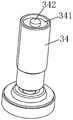
图4为本发明中脉冲阀的部分结构示意图;Fig. 4 is the partial structure schematic diagram of the pulse valve in the present invention;
图5为本发明中铁芯的结构示意图;Fig. 5 is the structural representation of the iron core in the present invention;
图6为本发明中定位件的结构示意图;6 is a schematic structural diagram of a positioning member in the present invention;
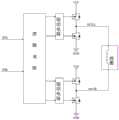
图7为本发明中控制电路的原理图。FIG. 7 is a schematic diagram of the control circuit in the present invention.
具体实施方式Detailed ways
为更进一步阐述本发明为达到预定目的所采取的技术手段及功效,以下结合附图及较佳实施例,对本发明的具体实施方式详细说明。In order to further illustrate the technical means and effects adopted by the present invention to achieve the predetermined purpose, the specific embodiments of the present invention are described in detail below with reference to the accompanying drawings and preferred embodiments.
请参照图1与图2,本发明实施例提供一种新型节能燃气灶调节阀体装置,包括:Referring to FIG. 1 and FIG. 2 , an embodiment of the present invention provides a novel energy-saving gas stove regulating valve device, including:
一截止阀1,在该截止阀1上形成有一进气口11;a shut-off
一比例阀2,在该比例阀2与截止阀1之间形成有一第一通气口21;a
一脉冲阀3,该脉冲阀3内具有一上腔体31与一下腔体32,在该上腔体 31内设置有一骨架33、设置于骨架33内侧且插入下腔体32内的一铁芯34、套设于骨架33外围的一线圈35、设置于线圈35一端且位于铁芯34外围的一永磁铁36、设置于下腔体32内且连接于铁芯34端部的一铁芯帽37、及套设于铁芯34外围且位于下腔体32内壁与铁芯帽37之间的一弹簧38,在该下腔体32内具有一第一阀口321,该铁芯帽37端部正对于第一阀口321设置;在该比例阀2与下腔体32之间形成有一第二通气口322,同时,在脉冲阀3上形成有一出气口12。A
本实施例截止阀1作为总阀,用于对进气进行控制。具体的,由进气口 11进入的燃气,由截止阀1对燃气是否能通过第一通气口21进入比例阀2 进行控制。而对于截止阀1的具体结构与工作原理,与本领域中常规的截止阀结构与原理相同。The cut-off
比例阀2用于对灶具火力大小进行调节。而对于比例阀2的具体结构与工作原理,与本领域中常规的比例阀结构与原理相同。The
脉冲阀3用于对灶具外环火的开启与关闭进行控制。具体的,在脉冲阀 3打开时,外环火开启点燃;在脉冲阀3关闭时,外环火关闭熄灭,而只剩下中心火。The
本实施例脉冲阀3的工作原理为:The working principle of the
当需要打开外环火时,通过控制电路向线圈35输入一方向电压,电压可以设定为正电压,也可以设定为负电压,线圈35通电后产生磁场,且线圈 35的磁极与永磁铁36的磁极相同,则线圈35产生的磁场与永磁铁36的磁场叠加,从而对铁芯34产生强磁吸力,该强磁吸力使得铁芯34瞬间朝远离第一阀口321的方向移动,压缩弹簧38,则此时,如图2所示,第一阀口321 打开,燃气可从第一阀口321通过,外环火打开点燃。接着,控制电路停止向线圈35输入电压,线圈35产生的磁场消失,而永磁铁36持续磁化铁芯 34,维持对铁芯34的磁吸力,使得铁芯34静止不动,则此时,第一阀口321 持续打开,外环火维持打开状态。由此可知,在维持第一阀口321打开状态,即外环火维持打开状态时,不需要给脉冲阀3通电,脉冲阀3处于断电状态,因此,大幅降低了电能的消耗。When the outer ring fire needs to be turned on, a voltage in one direction is input to the
当需要关闭外环火时,通过控制电路向线圈35输入反向电压,此处的电压与上述打开外环火时输入的电压正好相反,线圈35通电后产生磁场,且线圈35的磁极与永磁铁36的磁极相反,则线圈35产生的磁场抵消掉永磁铁36对铁芯34的磁吸力,在弹簧38的弹性恢复力作用下,铁芯34朝第一阀口321方向移动,铁芯帽37堵住第一阀口321,则此时,如图3所示,第一阀口321关闭,燃气无法从第一阀口321通过,外环火关闭熄灭。接着,控制电路停止向线圈35输入电压,线圈35产生的磁场消失,而永磁铁36对铁芯34的磁吸力无法触发铁芯34发生移动,则铁芯34维持静止状态,则此时,第一阀口321持续关闭,外环火维持关闭状态。由此可知,在维持第一阀口 321关闭状态,即外环火维持关闭状态时,不需要给脉冲阀3通电,脉冲阀3 处于断电状态,因此,大幅降低了电能的消耗。When the outer ring fire needs to be closed, a reverse voltage is input to the
本实施例控制电路如图7所示,用于向线圈35输入正反向电压。由控制电路向线圈35输入正好相反的电压,使得在线圈35通电产生磁场后,实现两种不同的功能:一是,线圈35的磁极与永磁铁36的磁极相同,由此,线圈35产生的磁场与永磁铁36的磁场叠加,从而对铁芯34产生强磁吸力,该强磁吸力使得铁芯34瞬间朝远离第一阀口321的方向移动,则第一阀口321 打开;二是,线圈35的磁极与永磁铁36的磁极相反,由此,线圈35产生的磁场抵消掉永磁铁36对铁芯34的磁吸力,在弹簧38的弹性恢复力作用下,铁芯34朝第一阀口321方向移动,铁芯帽37堵住第一阀口321,则此第一阀口321关闭。The control circuit of this embodiment is shown in FIG. 7 , and is used to input forward and reverse voltages to the
由上述可知,本实施例通过增设了永磁铁36的脉冲阀3结构设计,配合上可向线圈提供正反向电压的控制电路,只需要在脉冲阀3打开与关闭两个动作时向其通电,而在脉冲阀3维持工作时无需向其通电,由此,大幅降低了电能的消耗。因此,使得整个调节阀体装置功率降低,发热减少,并可选用较小功率的变压器,减少成本。As can be seen from the above, in this embodiment, the
在打开脉冲阀3时,铁芯34因受到强磁吸力上移,为了对铁芯34进行定位,本实施例在所述上腔体31内侧上壁设置有位于铁芯34正上方的一定位件39,对于定位件39的安装,本实施例在所述定位件39上端设置有卡入上腔体31内侧上壁的一安装凸块393。具体的,如图2、图3与图6所示,在该定位件39朝向铁芯34的一端部凸设有一定位凸台391,在该定位凸台 391上凹设有一定位槽392。同时,如图5所示,在所述铁芯34靠近定位件39的一端部上凹设有供定位凸台391卡入的一凹槽341,在该凹槽341内设置有与定位槽392相对应的一定位凸起342。在铁芯34因受到强磁吸力上移时,铁芯34的定位凸起342卡入定位件39的定位槽392中,定位件39的定位凸台391卡入铁芯34的凹槽341中,由此,对铁芯34进行定位,防止其偏移。When the
为了使铁芯34在发生动作时,能够竖直上下移动,本实施例在所述上腔体31内纵向设置有位于骨架33内的一导向轴套40,所述铁芯34与定位件 39设置于导向轴套40内。则铁芯34在发生动作时,能够在导向轴套40内竖直上下移动。In order to make the
对于永磁铁36的安装,本实施例在所述骨架33下端形成有一容置槽 331,所述永磁铁36设置于容置槽331内,如图2与图4所示。For the installation of the
对于弹簧38的安装,本实施例在所述下腔体32内侧顶部向下凸设有一上限位凸台323,在该铁芯帽37上设置有位于上限位凸台323正下方的一下限位凸台371,所述弹簧38上端套设于上限位凸台323外围,下端套设于下限位凸台371外围。在上限位凸台323与下限位凸台371的配合作用下,对弹簧38的安装位置、及弹性形变范围进行限制,利于在关闭脉冲阀3时,由弹簧38的弹性恢复力能够快速作用于铁芯34,使得铁芯34能够快速朝第一阀口321方向移动,关闭第一阀口321。For the installation of the
本实施例灶具调节阀体装置的工作原理为:打开灶具时,截止阀1、比例阀2与脉冲阀3全打开,接着,通过比例阀2可调节火力大小。当调节火力小到设定值时,给个脉冲信号给控制电路,由控制电路向线圈35通电,则脉冲阀3关掉,外环火熄灭,只剩下中心火;当通过比例阀2调节火力大到设定值时,给个脉冲信号给控制电路,由控制电路向线圈35通电,则脉冲阀 3打开,外环火点燃。The working principle of the adjusting valve body device of the cooker in this embodiment is as follows: when the cooker is turned on, the cut-off
本发明还提供了基于上述新型节能燃气灶调节阀体装置的外环火控制方法,包括以下步骤:The present invention also provides an outer ring fire control method based on the above-mentioned novel energy-saving gas stove regulating valve body device, comprising the following steps:
(1)打开外环火:(1) Open the outer ring fire:
(1.1)通过控制电路向线圈35输入一方向电压,线圈35通电后产生磁场,且线圈35的磁极与永磁铁36的磁极相同,则线圈35产生的磁场与永磁铁36的磁场叠加,从而对铁芯34产生强磁吸力,该强磁吸力使得铁芯34 瞬间朝远离第一阀口321的方向移动,压缩弹簧38,则此时,第一阀口321 打开,外环火打开;(1.1) Input a voltage in one direction to the
(1.2)接着,控制电路停止向线圈35输入电压,线圈35产生的磁场消失,而永磁铁36持续磁化铁芯34,维持对铁芯34的磁吸力,使得铁芯34 静止不动,则此时,第一阀口321持续打开,外环火维持打开状态;(1.2) Next, the control circuit stops inputting voltage to the
(2)关闭外环火:(2) Close the outer ring fire:
(2.1)通过控制电路向线圈35输入反向电压,线圈35通电后产生磁场,且线圈35的磁极与永磁铁36的磁极相反,则线圈35产生的磁场抵消掉永磁铁36对铁芯34的磁吸力,在弹簧38的弹性恢复力作用下,铁芯34朝第一阀口321方向移动,铁芯帽37堵住第一阀口321,则此时,第一阀口321关闭,外环火关闭;(2.1) Input a reverse voltage to the
(2.2)接着,控制电路停止向线圈35输入电压,线圈35产生的磁场消失,而永磁铁36对铁芯34的磁吸力无法触发铁芯34发生移动,则铁芯34 维持静止状态,则此时,第一阀口321持续关闭,外环火维持关闭状态。(2.2) Next, the control circuit stops inputting voltage to the
其中,所述步骤(1)与步骤(2)无先后顺序。Wherein, the step (1) and the step (2) are in no order.
由上述可知,本实施例通过脉冲阀3的特殊结构设计,并由控制电路向线圈提供正反向电压,则只需要在脉冲阀3打开与关闭两个动作时向其通电,而在脉冲阀3维持工作时无需向其通电,由此,大幅降低了电能的消耗。因此,使得整个调节阀体装置功率降低,发热减少,并可选用较小功率的变压器,减少成本。It can be seen from the above that in this embodiment, through the special structural design of the
以上所述,仅是本发明的较佳实施例而已,并非对本发明的技术范围作任何限制,故采用与本发明上述实施例相同或近似的技术特征,而得到的其他结构,均在本发明的保护范围之内。The above descriptions are only preferred embodiments of the present invention, and do not limit the technical scope of the present invention. Therefore, other structures obtained by adopting the same or similar technical features as the above-mentioned embodiments of the present invention are all within the scope of the present invention. within the scope of protection.
Claims (7)
Translated fromChinesePriority Applications (1)
| Application Number | Priority Date | Filing Date | Title |
|---|---|---|---|
| CN202010782237.5ACN112096925A (en) | 2020-08-06 | 2020-08-06 | A novel energy-saving gas stove regulating valve body device and outer ring fire control method |
Applications Claiming Priority (1)
| Application Number | Priority Date | Filing Date | Title |
|---|---|---|---|
| CN202010782237.5ACN112096925A (en) | 2020-08-06 | 2020-08-06 | A novel energy-saving gas stove regulating valve body device and outer ring fire control method |
Publications (1)
| Publication Number | Publication Date |
|---|---|
| CN112096925Atrue CN112096925A (en) | 2020-12-18 |
Family
ID=73750345
Family Applications (1)
| Application Number | Title | Priority Date | Filing Date |
|---|---|---|---|
| CN202010782237.5APendingCN112096925A (en) | 2020-08-06 | 2020-08-06 | A novel energy-saving gas stove regulating valve body device and outer ring fire control method |
Country Status (1)
| Country | Link |
|---|---|
| CN (1) | CN112096925A (en) |
Cited By (1)
| Publication number | Priority date | Publication date | Assignee | Title |
|---|---|---|---|---|
| CN113137500A (en)* | 2021-04-26 | 2021-07-20 | 广东万和热能科技有限公司 | Gas regulating valve and combustion device |
Citations (6)
| Publication number | Priority date | Publication date | Assignee | Title |
|---|---|---|---|---|
| CN200949680Y (en)* | 2006-09-15 | 2007-09-19 | 陆宝宏 | Pulse electromagnetic valve |
| CN202629271U (en)* | 2012-04-19 | 2012-12-26 | 余姚市永创电磁阀有限公司 | Self-hold electromagnetic valve |
| CN205425046U (en)* | 2016-03-22 | 2016-08-03 | 广东美的厨房电器制造有限公司 | Gas stoves |
| DE102016203602A1 (en)* | 2016-03-04 | 2017-09-07 | Zf Friedrichshafen Ag | Electromagnetic actuator and valve |
| CN210600301U (en)* | 2019-10-28 | 2020-05-22 | 中山骏业佳安特电器有限公司 | A cooker proportional valve structure |
| CN213236196U (en)* | 2020-08-06 | 2021-05-18 | 广东百威电子有限公司 | Novel energy-saving gas stove adjusting valve body device |
- 2020
- 2020-08-06CNCN202010782237.5Apatent/CN112096925A/enactivePending
Patent Citations (6)
| Publication number | Priority date | Publication date | Assignee | Title |
|---|---|---|---|---|
| CN200949680Y (en)* | 2006-09-15 | 2007-09-19 | 陆宝宏 | Pulse electromagnetic valve |
| CN202629271U (en)* | 2012-04-19 | 2012-12-26 | 余姚市永创电磁阀有限公司 | Self-hold electromagnetic valve |
| DE102016203602A1 (en)* | 2016-03-04 | 2017-09-07 | Zf Friedrichshafen Ag | Electromagnetic actuator and valve |
| CN205425046U (en)* | 2016-03-22 | 2016-08-03 | 广东美的厨房电器制造有限公司 | Gas stoves |
| CN210600301U (en)* | 2019-10-28 | 2020-05-22 | 中山骏业佳安特电器有限公司 | A cooker proportional valve structure |
| CN213236196U (en)* | 2020-08-06 | 2021-05-18 | 广东百威电子有限公司 | Novel energy-saving gas stove adjusting valve body device |
Cited By (1)
| Publication number | Priority date | Publication date | Assignee | Title |
|---|---|---|---|---|
| CN113137500A (en)* | 2021-04-26 | 2021-07-20 | 广东万和热能科技有限公司 | Gas regulating valve and combustion device |
Similar Documents
| Publication | Publication Date | Title |
|---|---|---|
| CN203258095U (en) | Fuel gas control ratio adjustment and pressure stability control device | |
| CN103867780A (en) | Fuel gas electromagnetism proportional valve | |
| CN111120716A (en) | A micro-power solenoid valve | |
| CN113503387A (en) | Gas proportional valve | |
| CN115306912A (en) | An injector device, an injector device control method, and a vehicle | |
| CN112096925A (en) | A novel energy-saving gas stove regulating valve body device and outer ring fire control method | |
| JP5473695B2 (en) | Motor safety valve | |
| CN217874334U (en) | Mechanical gas and air proportion regulating valve | |
| CN215110699U (en) | Gas regulating valve and combustion device | |
| CN213236196U (en) | Novel energy-saving gas stove adjusting valve body device | |
| CN110778755A (en) | Gas proportional valve | |
| CN108757992A (en) | A kind of gas ratio valve and water heater | |
| CN210600301U (en) | A cooker proportional valve structure | |
| CN110925447B (en) | Double disc magnetic stop regulating valve | |
| EP3726546B1 (en) | A dual coil solenoid valve for a fuel gas control valve and the control method thereof | |
| US6932101B2 (en) | Solenoid valve assembly for controlling gas supply | |
| CN204437396U (en) | A kind of hand push declines electric current gas electromagnetic valve | |
| CN219841039U (en) | Premixed air-fuel ratio valve and kitchen range | |
| CN206608600U (en) | The control device that a kind of pneumatic control valve valve positioner is used | |
| CN112747123A (en) | Gas valve | |
| CN205090061U (en) | Low -power consumption guide formula diaphragm solenoid valve | |
| CN211501668U (en) | Spring-free two-position two-way normally-open high-speed switch valve | |
| CN211820785U (en) | Double-valve-clack magnetic stop regulating valve | |
| CN108730601B (en) | Low-power consumption electromagnetic valve | |
| CN204459390U (en) | A kind of small-power gas ratio valve |
Legal Events
| Date | Code | Title | Description |
|---|---|---|---|
| PB01 | Publication | ||
| PB01 | Publication | ||
| SE01 | Entry into force of request for substantive examination | ||
| SE01 | Entry into force of request for substantive examination | ||
| RJ01 | Rejection of invention patent application after publication | Application publication date:20201218 |