CN112092686A - Adaptive seat comfort system based on fit of passenger and seat and adjusting method - Google Patents
Adaptive seat comfort system based on fit of passenger and seat and adjusting methodDownload PDFInfo
- Publication number
- CN112092686A CN112092686ACN202010841033.4ACN202010841033ACN112092686ACN 112092686 ACN112092686 ACN 112092686ACN 202010841033 ACN202010841033 ACN 202010841033ACN 112092686 ACN112092686 ACN 112092686A
- Authority
- CN
- China
- Prior art keywords
- seat
- module
- occupant
- air bag
- fit
- Prior art date
- Legal status (The legal status is an assumption and is not a legal conclusion. Google has not performed a legal analysis and makes no representation as to the accuracy of the status listed.)
- Pending
Links
Images


Classifications
- B—PERFORMING OPERATIONS; TRANSPORTING
- B60—VEHICLES IN GENERAL
- B60N—SEATS SPECIALLY ADAPTED FOR VEHICLES; VEHICLE PASSENGER ACCOMMODATION NOT OTHERWISE PROVIDED FOR
- B60N2/00—Seats specially adapted for vehicles; Arrangement or mounting of seats in vehicles
- B60N2/02—Seats specially adapted for vehicles; Arrangement or mounting of seats in vehicles the seat or part thereof being movable, e.g. adjustable
- B60N2/0224—Non-manual adjustments, e.g. with electrical operation
- B60N2/0244—Non-manual adjustments, e.g. with electrical operation with logic circuits
- B60N2/0268—Non-manual adjustments, e.g. with electrical operation with logic circuits using sensors or detectors for adapting the seat or seat part, e.g. to the position of an occupant
- B—PERFORMING OPERATIONS; TRANSPORTING
- B60—VEHICLES IN GENERAL
- B60N—SEATS SPECIALLY ADAPTED FOR VEHICLES; VEHICLE PASSENGER ACCOMMODATION NOT OTHERWISE PROVIDED FOR
- B60N2/00—Seats specially adapted for vehicles; Arrangement or mounting of seats in vehicles
- B60N2/002—Seats provided with an occupancy detection means mounted therein or thereon
- B60N2/0021—Seats provided with an occupancy detection means mounted therein or thereon characterised by the type of sensor or measurement
- B60N2/0024—Seats provided with an occupancy detection means mounted therein or thereon characterised by the type of sensor or measurement for identifying, categorising or investigation of the occupant or object on the seat
- B60N2/0027—Seats provided with an occupancy detection means mounted therein or thereon characterised by the type of sensor or measurement for identifying, categorising or investigation of the occupant or object on the seat for detecting the position of the occupant or of occupant's body part
- B—PERFORMING OPERATIONS; TRANSPORTING
- B60—VEHICLES IN GENERAL
- B60N—SEATS SPECIALLY ADAPTED FOR VEHICLES; VEHICLE PASSENGER ACCOMMODATION NOT OTHERWISE PROVIDED FOR
- B60N2/00—Seats specially adapted for vehicles; Arrangement or mounting of seats in vehicles
- B60N2/02—Seats specially adapted for vehicles; Arrangement or mounting of seats in vehicles the seat or part thereof being movable, e.g. adjustable
- B60N2/0224—Non-manual adjustments, e.g. with electrical operation
- B60N2/0244—Non-manual adjustments, e.g. with electrical operation with logic circuits
- B—PERFORMING OPERATIONS; TRANSPORTING
- B60—VEHICLES IN GENERAL
- B60N—SEATS SPECIALLY ADAPTED FOR VEHICLES; VEHICLE PASSENGER ACCOMMODATION NOT OTHERWISE PROVIDED FOR
- B60N2/00—Seats specially adapted for vehicles; Arrangement or mounting of seats in vehicles
- B60N2/90—Details or parts not otherwise provided for
- B60N2/914—Hydro-pneumatic adjustments of the shape
- B—PERFORMING OPERATIONS; TRANSPORTING
- B60—VEHICLES IN GENERAL
- B60N—SEATS SPECIALLY ADAPTED FOR VEHICLES; VEHICLE PASSENGER ACCOMMODATION NOT OTHERWISE PROVIDED FOR
- B60N2/00—Seats specially adapted for vehicles; Arrangement or mounting of seats in vehicles
- B60N2/002—Seats provided with an occupancy detection means mounted therein or thereon
- B60N2/0021—Seats provided with an occupancy detection means mounted therein or thereon characterised by the type of sensor or measurement
- B60N2/003—Seats provided with an occupancy detection means mounted therein or thereon characterised by the type of sensor or measurement characterised by the sensor mounting location in or on the seat
- B60N2/0033—Seats provided with an occupancy detection means mounted therein or thereon characterised by the type of sensor or measurement characterised by the sensor mounting location in or on the seat mounted on or in the foam cushion
- B—PERFORMING OPERATIONS; TRANSPORTING
- B60—VEHICLES IN GENERAL
- B60N—SEATS SPECIALLY ADAPTED FOR VEHICLES; VEHICLE PASSENGER ACCOMMODATION NOT OTHERWISE PROVIDED FOR
- B60N2/00—Seats specially adapted for vehicles; Arrangement or mounting of seats in vehicles
- B60N2/002—Seats provided with an occupancy detection means mounted therein or thereon
- B60N2/0021—Seats provided with an occupancy detection means mounted therein or thereon characterised by the type of sensor or measurement
- B60N2/003—Seats provided with an occupancy detection means mounted therein or thereon characterised by the type of sensor or measurement characterised by the sensor mounting location in or on the seat
- B60N2/0034—Seats provided with an occupancy detection means mounted therein or thereon characterised by the type of sensor or measurement characterised by the sensor mounting location in or on the seat in, under or on the seat cover
- B—PERFORMING OPERATIONS; TRANSPORTING
- B60—VEHICLES IN GENERAL
- B60N—SEATS SPECIALLY ADAPTED FOR VEHICLES; VEHICLE PASSENGER ACCOMMODATION NOT OTHERWISE PROVIDED FOR
- B60N2/00—Seats specially adapted for vehicles; Arrangement or mounting of seats in vehicles
- B60N2/002—Seats provided with an occupancy detection means mounted therein or thereon
- B60N2/0021—Seats provided with an occupancy detection means mounted therein or thereon characterised by the type of sensor or measurement
- B60N2/0035—Seats provided with an occupancy detection means mounted therein or thereon characterised by the type of sensor or measurement characterised by the sensor data transmission, e.g. wired connections or wireless transmitters therefor; characterised by the sensor data processing, e.g. seat sensor signal amplification or electric circuits for providing seat sensor information
- B—PERFORMING OPERATIONS; TRANSPORTING
- B60—VEHICLES IN GENERAL
- B60N—SEATS SPECIALLY ADAPTED FOR VEHICLES; VEHICLE PASSENGER ACCOMMODATION NOT OTHERWISE PROVIDED FOR
- B60N2/00—Seats specially adapted for vehicles; Arrangement or mounting of seats in vehicles
- B60N2/02—Seats specially adapted for vehicles; Arrangement or mounting of seats in vehicles the seat or part thereof being movable, e.g. adjustable
- B60N2/0224—Non-manual adjustments, e.g. with electrical operation
- B60N2/0244—Non-manual adjustments, e.g. with electrical operation with logic circuits
- B60N2/026—Non-manual adjustments, e.g. with electrical operation with logic circuits varying hardness or support of upholstery, e.g. for tuning seat comfort when driving curved roads
- B—PERFORMING OPERATIONS; TRANSPORTING
- B60—VEHICLES IN GENERAL
- B60N—SEATS SPECIALLY ADAPTED FOR VEHICLES; VEHICLE PASSENGER ACCOMMODATION NOT OTHERWISE PROVIDED FOR
- B60N2210/00—Sensor types, e.g. for passenger detection systems or for controlling seats
- B60N2210/10—Field detection presence sensors
- B60N2210/12—Capacitive; Electric field
- B—PERFORMING OPERATIONS; TRANSPORTING
- B60—VEHICLES IN GENERAL
- B60N—SEATS SPECIALLY ADAPTED FOR VEHICLES; VEHICLE PASSENGER ACCOMMODATION NOT OTHERWISE PROVIDED FOR
- B60N2210/00—Sensor types, e.g. for passenger detection systems or for controlling seats
- B60N2210/30—Temperature sensors
- B—PERFORMING OPERATIONS; TRANSPORTING
- B60—VEHICLES IN GENERAL
- B60N—SEATS SPECIALLY ADAPTED FOR VEHICLES; VEHICLE PASSENGER ACCOMMODATION NOT OTHERWISE PROVIDED FOR
- B60N2210/00—Sensor types, e.g. for passenger detection systems or for controlling seats
- B60N2210/40—Force or pressure sensors
- B60N2210/44—Force or pressure sensors using fluids
- B—PERFORMING OPERATIONS; TRANSPORTING
- B60—VEHICLES IN GENERAL
- B60N—SEATS SPECIALLY ADAPTED FOR VEHICLES; VEHICLE PASSENGER ACCOMMODATION NOT OTHERWISE PROVIDED FOR
- B60N2220/00—Computerised treatment of data for controlling of seats
- B60N2220/10—Computerised treatment of data for controlling of seats using a database
- B—PERFORMING OPERATIONS; TRANSPORTING
- B60—VEHICLES IN GENERAL
- B60N—SEATS SPECIALLY ADAPTED FOR VEHICLES; VEHICLE PASSENGER ACCOMMODATION NOT OTHERWISE PROVIDED FOR
- B60N2230/00—Communication or electronic aspects
- B60N2230/10—Wired data transmission
Landscapes
- Engineering & Computer Science (AREA)
- Aviation & Aerospace Engineering (AREA)
- Transportation (AREA)
- Mechanical Engineering (AREA)
- Seats For Vehicles (AREA)
- Air Bags (AREA)
- Chair Legs, Seat Parts, And Backrests (AREA)
Abstract
Description
Translated fromChinese技术领域technical field
本发明涉及车载座椅系统技术领域,具体地说是基于乘员与座椅贴合度的自适应座椅舒适系统及调节方法。The invention relates to the technical field of in-vehicle seat systems, in particular to an adaptive seat comfort system and an adjustment method based on the degree of fit between occupants and the seat.
背景技术Background technique
当前汽车的舒适性越来越重要,而车辆座椅系统在很大程度上影响着乘坐的舒适性。传统汽车座椅舒适系统的控制主要通过按键和车辆通讯去调整座椅各个支撑气袋的位置,一方面每个乘员的坐姿和体型不同,造成了乘员需要不断手动调整各个支撑气袋的位置,用户体验感不好。另一方面手动调节限制了气袋数量,从而无法实现座椅与人体最大可能性贴合,降低了座椅的舒适性和支撑性。The comfort of the current car is more and more important, and the vehicle seat system greatly affects the comfort of the ride. The control of the traditional car seat comfort system mainly adjusts the position of each support airbag in the seat through buttons and vehicle communication. Bad user experience. On the other hand, manual adjustment limits the number of air bags, so that the maximum possible fit of the seat and the human body cannot be achieved, which reduces the comfort and support of the seat.
发明内容SUMMARY OF THE INVENTION
本发明为克服现有技术的不足,提供一种基于乘员与座椅贴合度的自适应座椅舒适系统及调节方法,进一步实现智能动态调节,通过布置在座椅舒适系统上的传感电路检测乘员在座椅上的贴合度,动态的调整各部位的支撑位置。In order to overcome the deficiencies of the prior art, the present invention provides an adaptive seat comfort system and an adjustment method based on the fit between the occupant and the seat, and further realizes intelligent dynamic adjustment. Detect the fit of the occupant on the seat, and dynamically adjust the support position of each part.
为实现上述目的,设计一种基于乘员与座椅贴合度的自适应座椅舒适系统,包括ECU控制系统,其特征在于:所述的ECU控制系统内设有通讯模块、微控制器、电源模块、座椅与乘员贴合度检测模块及舒适度调节模块,座椅与乘员贴合度检测模块及舒适度调节模块通过线路双向连接微控制器,微控制器模块通过线路双向连接通讯模块。In order to achieve the above purpose, an adaptive seat comfort system based on the fit between the occupant and the seat is designed, including an ECU control system, which is characterized in that: the ECU control system is provided with a communication module, a microcontroller, a power supply The module, the seat and occupant fit detection module and the comfort adjustment module, the seat and occupant fit detection module and the comfort adjustment module are bidirectionally connected to the microcontroller through the line, and the microcontroller module is bidirectionally connected to the communication module through the line.
所述的电源模块通过线路连接通讯模块、微控制器及座椅与乘员贴合度检测模块及舒适度调节模块。The power module is connected to the communication module, the microcontroller, the seat-occupant fit detection module and the comfort adjustment module through a line.
所述的座椅与乘员贴合度检测模块及舒适度调节模块包括气阀驱动模块、电容量检测模块、气压温度检测模块,气泵驱动模块,电容量检测模块通过线路双向连接微控制器,微控制器的输出端分别与气阀驱动模块及气泵驱动模块连接,所述的气阀驱动模块通过控制阀控制器与气袋连接;所述的气泵驱动模块通过线路与气泵连接。The seat-occupant fit detection module and the comfort adjustment module include a valve drive module, a capacitance detection module, an air pressure and temperature detection module, an air pump drive module, and the capacitance detection module is bidirectionally connected to the microcontroller through a line, and the micro The output end of the controller is respectively connected with the air valve driving module and the air pump driving module, the air valve driving module is connected with the air bag through the control valve controller; the air pump driving module is connected with the air pump through the line.
所述的气阀驱动模块包括但不限于电磁阀,记忆合金丝。The air valve driving module includes but is not limited to solenoid valve and memory alloy wire.
所述的气袋位于汽车座椅内部,并且气袋至少设有1个,气袋的底部连接毛毡,位于气袋的表面均布设有若干传感器电阻丝,所述的传感器电阻丝与电容量检测电路连接。The air bag is located inside the car seat, and there is at least one air bag. The bottom of the air bag is connected to a felt, and a number of sensor resistance wires are evenly distributed on the surface of the air bag. circuit connection.
所述的系统的具体工作流程如下:The specific workflow of the system is as follows:
(1)开始;(1) start;
(2)硬件初始化;(2) Hardware initialization;
(3)系统变量初始化;(3) System variable initialization;
(4)系统检测当前所有气袋上的电容值是否在标定范围内,是则结束;否则进行周期性逐个检测气袋上的电容值;(4) The system checks whether the current capacitance values on all air bags are within the calibration range, and if so, it ends; otherwise, it periodically detects the capacitance values on the air bags one by one;
(5)检测某个气袋上的电容值,并判断该电容值是否超过阀值1,是则打开该气袋的充气控制阀;否则判断该电容值是否超过阀值2;(5) Detect the capacitance value of a certain air bag, and judge whether the capacitance value exceeds the
(6)打开该气袋的充气控制阀;(6) Open the inflation control valve of the air bag;
(7)控制阀开启气泵工作;(7) The control valve opens the air pump to work;
(8)判断该电容值是否超过阀值2,是则关闭该气袋的充气控制阀,否则判断该电容值是否小于阀值3;(8) Determine whether the capacitance value exceeds the
(9)关闭该气袋的充气控制阀;(9) Close the inflation control valve of the air bag;
(10) 控制阀关闭气泵工作;(10) The control valve closes the air pump to work;
(11) 判断该电容值是否小于阀值3,是则打开该气袋的充气控制阀;否则进行下一个气袋上电容量的检测;(11) Determine whether the capacitance value is less than the
(12) 打开该气袋的充气控制阀;(12) Open the inflation control valve of the air bag;
(13) 控制阀开启气泵工作;(13) The control valve opens the air pump to work;
(14) 进行下一个气袋上电容量的检测,重复步骤(4)。(14) Carry out the detection of the electric capacity of the next air bag, and repeat step (4).
所述的阀值1为判断是否充气动作的数值;所述的阀值2为判断是否停止充气动作的数值;所述的阀值3为判断是否放气动作的数值;阀值3的数值小于阀值1的数值,阀值1的数值小于阀值2的数值。The
所述的系统变量包括系统标定已完成标志、系统初始化检测已完成标志、关键算法数据检测已完成标志。The system variables include a system calibration completed flag, a system initialization detection completed flag, and a key algorithm data detection completed flag.
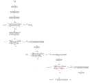
所述的电容量的检测的具体方法为利用传感器电阻丝的接触面积及传感器电阻丝之间的距离,通过公式

本发明同现有技术相比,提供一种基于乘员与座椅贴合度的自适应座椅舒适系统及调节方法,进一步实现智能动态调节,通过布置在座椅舒适系统上的传感电路检测乘员在座椅上的贴合度,动态的调整各部位的支撑位置。Compared with the prior art, the present invention provides an adaptive seat comfort system and an adjustment method based on the fit between the occupant and the seat, further realizes intelligent dynamic adjustment, and detects through a sensing circuit arranged on the seat comfort system. The fit of the occupant on the seat can dynamically adjust the support position of each part.
附图说明Description of drawings
图1,图2为本发明系统框架连接图。FIG. 1 and FIG. 2 are connection diagrams of the system framework of the present invention.
图3为气袋及传感器电阻丝连接结构示意图。FIG. 3 is a schematic diagram of the connection structure of the air bag and the sensor resistance wire.
图4为本发明软件流程图。Fig. 4 is the software flow chart of the present invention.
具体实施方式Detailed ways
下面根据附图对本发明做进一步的说明。The present invention will be further described below according to the accompanying drawings.
如图1,图2所示,ECU控制系统内设有通讯模块、微控制器、电源模块、座椅与乘员贴合度检测模块及舒适度调节模块,座椅与乘员贴合度检测模块及舒适度调节模块通过线路双向连接微控制器,微控制器模块通过线路双向连接通讯模块。As shown in Figure 1 and Figure 2, the ECU control system is equipped with a communication module, a microcontroller, a power supply module, a seat-occupant fit detection module and a comfort adjustment module, and a seat-occupant fit detection module and The comfort adjustment module is bidirectionally connected to the microcontroller through the line, and the microcontroller module is bidirectionally connected to the communication module through the line.
电源模块通过线路连接通讯模块、微控制器及座椅与乘员贴合度检测模块及舒适度调节模块。The power module is connected to the communication module, the microcontroller, the seat-occupant fit detection module and the comfort adjustment module through a line.
座椅与乘员贴合度检测模块及舒适度调节模块包括气阀驱动模块、电容量检测模块、气压温度检测模块,气泵驱动模块,电容量检测模块通过线路双向连接微控制器,微控制器的输出端分别与气阀驱动模块及气泵驱动模块连接,所述的气阀驱动模块通过控制阀控制器与气袋连接;所述的气泵驱动模块通过线路与气泵连接。The seat-occupant fit detection module and the comfort adjustment module include an air valve drive module, a capacitance detection module, an air pressure and temperature detection module, an air pump drive module, and the capacitance detection module is bidirectionally connected to the microcontroller through a line. The output ends are respectively connected with the air valve driving module and the air pump driving module, the air valve driving module is connected with the air bag through the control valve controller; the air pump driving module is connected with the air pump through the line.
气阀驱动模块包括但不限于电磁阀,记忆合金丝。The valve drive module includes but is not limited to solenoid valve, memory alloy wire.
如图3所示,气袋位于汽车座椅内部,并且气袋2至少设有1个,气袋2的数量可由客户自由定义,气袋2的底部连接毛毡4,位于气袋2的表面均布设有若干传感器电阻丝3,所述的传感器电阻丝3与电容量检测电路1连接。该电容量检测电路为常规电路,即主控制器MCU可以通过IIC,SPI总线或者AD方式读取电容量检测电路的多通道电容量值,电容量检测电路可以用常规的多通道高速电容数字转换器芯片,特殊应用集成电路或模拟电路完成。As shown in Figure 3, the air bag is located inside the car seat, and there is at least one
如图4所示,本发明的系统的具体工作流程如下:As shown in Figure 4, the concrete workflow of the system of the present invention is as follows:
(1)开始;(1) start;
(2)硬件初始化;(2) Hardware initialization;
(3)系统变量初始化;(3) System variable initialization;
(4)系统检测当前所有气袋上的电容值是否在标定范围内,是则结束;否则进行周期性逐个检测气袋上的电容值;(4) The system checks whether the current capacitance values on all air bags are within the calibration range, and if so, it ends; otherwise, it periodically detects the capacitance values on the air bags one by one;
(5)检测某个气袋上的电容值,并判断该电容值是否超过阀值1,是则打开该气袋的充气控制阀;否则判断该电容值是否超过阀值2;(5) Detect the capacitance value of a certain air bag, and judge whether the capacitance value exceeds the
(6)打开该气袋的充气控制阀;(6) Open the inflation control valve of the air bag;
(7)控制阀开启气泵工作;(7) The control valve opens the air pump to work;
(8)判断该电容值是否超过阀值2,是则关闭该气袋的充气控制阀,否则判断该电容值是否小于阀值3;(8) Determine whether the capacitance value exceeds the
(9)关闭该气袋的充气控制阀;(9) Close the inflation control valve of the air bag;
(10) 控制阀关闭气泵工作;(10) The control valve closes the air pump to work;
(11) 判断该电容值是否小于阀值3,是则打开该气袋的充气控制阀;否则进行下一个气袋上电容量的检测;(11) Determine whether the capacitance value is less than the
(12) 打开该气袋的充气控制阀;(12) Open the inflation control valve of the air bag;
(13) 控制阀开启气泵工作;(13) The control valve opens the air pump to work;
(14) 进行下一个气袋上电容量的检测,重复步骤(4)。(14) Carry out the detection of the electric capacity of the next air bag, and repeat step (4).
阀值1为判断是否充气动作的数值;所述的阀值2为判断是否停止充气动作的数值;所述的阀值3为判断是否放气动作的数值;阀值3的数值小于阀值1的数值,阀值1的数值小于阀值2的数值。
系统变量包括系统标定已完成标志、系统初始化检测已完成标志、关键算法数据检测已完成标志。System variables include system calibration completed flags, system initialization detection completed flags, and key algorithm data detection completed flags.
电容量的检测的具体方法为利用传感器电阻丝的接触面积及传感器电阻丝之间的距离,通过公式

本发明所使用的传感器并非传统意义上的电容传感器,而是使用电阻丝进行定制形状的排列从而实现传感器的功能。该方式具有成本低,定制化程度高,寿命长,抗干扰能力强等特点。The sensor used in the present invention is not a capacitive sensor in the traditional sense, but uses a resistance wire to perform a custom-shaped arrangement to realize the function of the sensor. This method has the characteristics of low cost, high degree of customization, long life and strong anti-interference ability.
传感电路是一个通过测量乘员对传感电路的电容量的变化来控制各个气袋的充气和放气的技术,相对于传统手动调整各个气袋,自适应座椅舒适系统具有动态调整舒适系统,提高乘员舒适度的个性化。The sensing circuit is a technology that controls the inflation and deflation of each air bag by measuring the change in the capacitance of the occupant to the sensing circuit. Compared with the traditional manual adjustment of each air bag, the adaptive seat comfort system has a dynamic adjustment comfort system. , personalization to improve occupant comfort.
座椅舒适系统的气袋充气和放气功能会影响乘员与气袋上传感电阻丝之间的距离和接触面积,从而导致电容量的变化。本发明的座椅与乘员贴合度检测模块及舒适度调节模块通过不同通道的电容量变化,通过算法判断出各个气袋需要调整的信息,座椅舒适系统根据座椅与乘员贴合度检测系统的信息,调整系统内各个针对人体各部位气袋的支撑的位置,满足不同乘员的舒适性和个性化,并且会根据乘员所穿服饰的薄厚进行自适应调节,无需特殊参数设置,从而实现乘员在不同季节温度条件下都得道同样的舒适性。The air bag inflation and deflation functions of the seat comfort system affect the distance and contact area between the occupant and the sensing resistance wire on the air bag, resulting in changes in electrical capacity. The seat and occupant fit detection module and the comfort adjustment module of the present invention determine the information that each air bag needs to be adjusted through the change of the capacitance of different channels, and the seat comfort system detects the fit of the seat and the occupant according to the algorithm. System information, adjust the position of each airbag support in the system for various parts of the human body to meet the comfort and individuality of different occupants, and adaptively adjust according to the thickness of the clothing worn by the occupants, without the need for special parameter settings, so as to achieve Occupants receive the same comfort in different seasonal temperature conditions.
本发明采用车载微控制器MCU芯片,通过车载总线汽车总线相接,为了自适应不同厂家的总线通讯协议,硬件上集成了CAN总线、LIN线总线物理接口。The invention adopts the on-board microcontroller MCU chip, which is connected to the car bus through the on-board bus. In order to adapt to the bus communication protocols of different manufacturers, the hardware integrates the physical interfaces of the CAN bus and the LIN line bus.
电源模块采用LDO电源系统,通过MCU对功耗进行管理。电源管理分为深度睡眠与轻度睡眠两种情况,极大的降低了终端的静态功耗,完全通过汽车低功耗的认证。The power module adopts the LDO power system, and manages the power consumption through the MCU. Power management is divided into deep sleep and light sleep, which greatly reduces the static power consumption of the terminal and completely passes the certification of automotive low power consumption.
电容量检测模块采用专有的电容采取模块,采用总线方式读取电容导线的电容量,相对于空位置的电容量,通过数据去冗余和抖动等方法,获取乘员位置的变化,进一步驱动座椅舒适系统的控制阀门,以十分精准的方式控制阀门开启与关闭,从而调整系统内各个针对人体各部位气袋的支撑的位置,满足乘员的舒适性。同时为了系统可靠性,电路上增加短路与开路检测功能。The capacitance detection module adopts a proprietary capacitance acquisition module, and uses the bus method to read the capacitance of the capacitance wire, relative to the capacitance of the empty position, through data de-redundancy and jitter, etc., to obtain the change of the occupant's position, and further drive the seat. The control valve of the seat comfort system controls the opening and closing of the valve in a very precise way, so as to adjust the position of the air bags in the system for various parts of the human body to meet the comfort of the occupants. At the same time, for system reliability, short circuit and open circuit detection functions are added to the circuit.
Claims (9)
Translated fromChinese

Priority Applications (6)
| Application Number | Priority Date | Filing Date | Title |
|---|---|---|---|
| CN202010841033.4ACN112092686A (en) | 2020-08-20 | 2020-08-20 | Adaptive seat comfort system based on fit of passenger and seat and adjusting method |
| PCT/CN2021/108038WO2022037357A1 (en) | 2020-08-20 | 2021-07-23 | Adaptive seat comfort system based on passenger-seat fit degree, and adjustment method |
| KR1020237009519AKR20230051705A (en) | 2020-08-20 | 2021-07-23 | Self-adaptive seat comfort system and adjustment method based on the degree of adhesion between the occupant and the seat |
| EP21857452.3AEP4215412A4 (en) | 2020-08-20 | 2021-07-23 | ADAPTIVE SEAT COMFORT SYSTEM BASED ON PASSENGER SEAT ADJUSTMENT DEGREE, AND ADJUSTMENT METHOD |
| JP2023512422AJP7550305B2 (en) | 2020-08-20 | 2021-07-23 | Adaptive seat comfort system and adjustment method based on degree of fit between occupant and seat |
| US18/041,953US12377758B2 (en) | 2020-08-20 | 2021-07-23 | Adaptive seat comfort system based on passenger-seat fit degree, and adjustment method |
Applications Claiming Priority (1)
| Application Number | Priority Date | Filing Date | Title |
|---|---|---|---|
| CN202010841033.4ACN112092686A (en) | 2020-08-20 | 2020-08-20 | Adaptive seat comfort system based on fit of passenger and seat and adjusting method |
Publications (1)
| Publication Number | Publication Date |
|---|---|
| CN112092686Atrue CN112092686A (en) | 2020-12-18 |
Family
ID=73754011
Family Applications (1)
| Application Number | Title | Priority Date | Filing Date |
|---|---|---|---|
| CN202010841033.4APendingCN112092686A (en) | 2020-08-20 | 2020-08-20 | Adaptive seat comfort system based on fit of passenger and seat and adjusting method |
Country Status (6)
| Country | Link |
|---|---|
| US (1) | US12377758B2 (en) |
| EP (1) | EP4215412A4 (en) |
| JP (1) | JP7550305B2 (en) |
| KR (1) | KR20230051705A (en) |
| CN (1) | CN112092686A (en) |
| WO (1) | WO2022037357A1 (en) |
Cited By (2)
| Publication number | Priority date | Publication date | Assignee | Title |
|---|---|---|---|---|
| CN113787940A (en)* | 2021-08-24 | 2021-12-14 | 艾福迈汽车系统(上海)有限公司 | Self-adaptive seat adjusting system based on composite sensing |
| WO2022037357A1 (en)* | 2020-08-20 | 2022-02-24 | 艾福迈汽车系统(上海)有限公司 | Adaptive seat comfort system based on passenger-seat fit degree, and adjustment method |
Citations (5)
| Publication number | Priority date | Publication date | Assignee | Title |
|---|---|---|---|---|
| US5170364A (en)* | 1990-12-06 | 1992-12-08 | Biomechanics Corporation Of America | Feedback system for load bearing surface |
| US6088642A (en)* | 1998-07-29 | 2000-07-11 | Mccord Winn Textron Inc. | Interactive, individually controlled, multiple bladder seating comfort adjustment system and method |
| CN101734175A (en)* | 2008-11-26 | 2010-06-16 | 财团法人工业技术研究院 | Racing car seat and operation method thereof |
| CN109606210A (en)* | 2019-01-25 | 2019-04-12 | 浙江吉利汽车研究院有限公司 | Intelligent sensor seat and car |
| US20190193591A1 (en)* | 2017-12-21 | 2019-06-27 | Lear Corporation | Occupant and fidget detection of a seat assembly |
Family Cites Families (28)
| Publication number | Priority date | Publication date | Assignee | Title |
|---|---|---|---|---|
| US11617451B1 (en)* | 2004-12-07 | 2023-04-04 | Steven Jerome Caruso | Custom controlled seating surface technologies |
| JP5586827B2 (en) | 2007-10-23 | 2014-09-10 | テイ・エス テック株式会社 | Sheet |
| US20100289302A1 (en)* | 2009-05-14 | 2010-11-18 | Nitring Enterprise Inc. | Seat adjusting method and system thereof |
| JP2012032342A (en) | 2010-08-02 | 2012-02-16 | Toyota Boshoku Corp | Occupant detection apparatus |
| JP5996542B2 (en)* | 2010-10-07 | 2016-09-21 | フォルシア・オートモーティブ・シーティング・リミテッド・ライアビリティ・カンパニーFaurecia Automotive Seating, Llc | Systems, methods, and components that capture, analyze, and use details about the occupant's body to improve seat structure and environmental configuration |
| US11372936B2 (en)* | 2013-04-15 | 2022-06-28 | Autoconnect Holdings Llc | System and method for adapting a control function based on a user profile |
| US9504416B2 (en)* | 2013-07-03 | 2016-11-29 | Sleepiq Labs Inc. | Smart seat monitoring system |
| CN104627031B (en)* | 2013-11-06 | 2017-06-16 | 郑镜峰 | air bag car seat |
| GB2528062B (en)* | 2014-07-08 | 2016-10-19 | Jaguar Land Rover Ltd | Massage control system for a vehicle |
| US20170158088A1 (en) | 2015-12-04 | 2017-06-08 | Adient Luxembourg Holding S.Á.R.L. | Seat contour control system and method |
| US9827888B2 (en)* | 2016-01-04 | 2017-11-28 | Lear Corporation | Seat assemblies with adjustable side bolster actuators |
| US10137802B2 (en)* | 2016-03-11 | 2018-11-27 | Ford Global Technologies, Llc | Detecting occupant presence on a vehicle seat |
| US10632866B2 (en)* | 2016-06-03 | 2020-04-28 | Faurecia Automotive Seating, Llc | Movement system for a vehicle seat |
| US20170361746A1 (en)* | 2016-06-15 | 2017-12-21 | Lear Corporation | Adjustable seat assembly and vehicle assembly |
| JP2018100054A (en)* | 2016-12-21 | 2018-06-28 | トヨタ自動車株式会社 | Air supply device and vehicle seat |
| JP6421365B2 (en)* | 2017-02-10 | 2018-11-14 | 本田技研工業株式会社 | Vehicle seat control system, vehicle seat control method, and program |
| CN206664359U (en)* | 2017-03-23 | 2017-11-24 | 沈阳金杯安道拓汽车部件有限公司 | Driver chair of automobile with flank adjusting means |
| CN107599919A (en) | 2017-09-04 | 2018-01-19 | 中国第汽车股份有限公司 | A kind of self-adapted car seat |
| CN207657658U (en) | 2017-09-04 | 2018-07-27 | 中国第一汽车股份有限公司 | A kind of self-adapted car seat |
| US10214118B1 (en)* | 2017-12-01 | 2019-02-26 | GM Global Technology Operations LLC | Systems, methods and apparatuses are provided for automated passenger seat adjustments in a vehicle |
| CN108237953B (en) | 2017-12-22 | 2020-07-07 | 浙江吉利汽车研究院有限公司 | Intelligent adjusting system and method for automobile seat |
| KR20200034106A (en) | 2018-09-21 | 2020-03-31 | 현대자동차주식회사 | Seat system for self-driving vehicle |
| US20210016686A1 (en)* | 2019-07-17 | 2021-01-21 | Lear Corporation | Seat assembly and method |
| US11135950B2 (en)* | 2019-12-05 | 2021-10-05 | Lear Corporation | Therapeutic technology fusion |
| WO2021183823A1 (en)* | 2020-03-11 | 2021-09-16 | Georgia Tech Research Corporation | Systems and methods for enhancing comfort individuals in contact with surfaces |
| DE102021115618A1 (en)* | 2020-06-25 | 2021-12-30 | Alfmeier Präzision SE | Circuit arrangement for controlling seat comfort systems, seat and method for controlling a seat comfort system |
| CN112092686A (en) | 2020-08-20 | 2020-12-18 | 艾福迈汽车系统(上海)有限公司 | Adaptive seat comfort system based on fit of passenger and seat and adjusting method |
| EP4088976A1 (en)* | 2021-05-11 | 2022-11-16 | Technische Hochschule Ingolstadt | Systems and method for estimating and monitoring occupant injury level in real time in vehicle crashes |
- 2020
- 2020-08-20CNCN202010841033.4Apatent/CN112092686A/enactivePending
- 2021
- 2021-07-23KRKR1020237009519Apatent/KR20230051705A/enactivePending
- 2021-07-23WOPCT/CN2021/108038patent/WO2022037357A1/ennot_activeCeased
- 2021-07-23JPJP2023512422Apatent/JP7550305B2/enactiveActive
- 2021-07-23USUS18/041,953patent/US12377758B2/enactiveActive
- 2021-07-23EPEP21857452.3Apatent/EP4215412A4/enactivePending
Patent Citations (5)
| Publication number | Priority date | Publication date | Assignee | Title |
|---|---|---|---|---|
| US5170364A (en)* | 1990-12-06 | 1992-12-08 | Biomechanics Corporation Of America | Feedback system for load bearing surface |
| US6088642A (en)* | 1998-07-29 | 2000-07-11 | Mccord Winn Textron Inc. | Interactive, individually controlled, multiple bladder seating comfort adjustment system and method |
| CN101734175A (en)* | 2008-11-26 | 2010-06-16 | 财团法人工业技术研究院 | Racing car seat and operation method thereof |
| US20190193591A1 (en)* | 2017-12-21 | 2019-06-27 | Lear Corporation | Occupant and fidget detection of a seat assembly |
| CN109606210A (en)* | 2019-01-25 | 2019-04-12 | 浙江吉利汽车研究院有限公司 | Intelligent sensor seat and car |
Cited By (4)
| Publication number | Priority date | Publication date | Assignee | Title |
|---|---|---|---|---|
| WO2022037357A1 (en)* | 2020-08-20 | 2022-02-24 | 艾福迈汽车系统(上海)有限公司 | Adaptive seat comfort system based on passenger-seat fit degree, and adjustment method |
| US12377758B2 (en) | 2020-08-20 | 2025-08-05 | Alfmeier Automotive Systems (Shanghai) Co. Ltd. | Adaptive seat comfort system based on passenger-seat fit degree, and adjustment method |
| CN113787940A (en)* | 2021-08-24 | 2021-12-14 | 艾福迈汽车系统(上海)有限公司 | Self-adaptive seat adjusting system based on composite sensing |
| WO2023024226A1 (en)* | 2021-08-24 | 2023-03-02 | 艾福迈汽车系统(上海)有限公司 | Adaptive seat adjustment system based on composite sensing |
Also Published As
| Publication number | Publication date |
|---|---|
| JP2023537788A (en) | 2023-09-05 |
| WO2022037357A1 (en) | 2022-02-24 |
| EP4215412A1 (en) | 2023-07-26 |
| EP4215412A4 (en) | 2024-12-18 |
| US20230311717A1 (en) | 2023-10-05 |
| KR20230051705A (en) | 2023-04-18 |
| US12377758B2 (en) | 2025-08-05 |
| JP7550305B2 (en) | 2024-09-12 |
Similar Documents
| Publication | Publication Date | Title |
|---|---|---|
| WO2022037357A1 (en) | Adaptive seat comfort system based on passenger-seat fit degree, and adjustment method | |
| CN110884315A (en) | An intelligent electronically controlled air suspension system for commercial vehicles | |
| US20160362023A1 (en) | SMA Valve for Controlling Air Supply to an Air Cell in a Vehicle Seat | |
| CN201363848Y (en) | Vehicle air conditioner control system | |
| CN101382027A (en) | Bicycle Window Repositioning to Mitigate Wind Pressure Pulsations in Vehicle Cabins | |
| CN105172492B (en) | A kind of bicycle intelligence pressure-sensitive aerating device | |
| CN105059075A (en) | Two-stage regulating system and method of height of car body | |
| CN112009314B (en) | Vehicle seat side wing adjusting method, device and system | |
| CN110338591A (en) | A kind of intelligence mattress adaptation electric blanket system | |
| CN215361069U (en) | Car seat massage device and car seat | |
| CN102975669A (en) | Driver identity identification device and method | |
| CN110606008A (en) | Automatic adjusting control method for automobile seat and automobile seat | |
| CN115742652B (en) | An electronically controlled suspension control method, device and storage medium | |
| CN113273862B (en) | Intelligent pillow capable of judging sleeping posture according to shoulder pressure distribution | |
| CN109398301A (en) | A kind of car belt feint spike identifying system and its recognition methods | |
| CN107985428A (en) | Driver's cabin systems stabilisation | |
| CN202966190U (en) | Driver identity recognition device | |
| KR20010061858A (en) | seat with of automatically adjustable profile | |
| KR20140121062A (en) | Identfifying driver using pressure sensor in car seat | |
| CN115742889A (en) | Self-adaptive comfortable air bag adjusting system, adjustable seat and adjusting method | |
| KR20130057624A (en) | Control device for automotive vehicles | |
| CN118906928A (en) | Self-adaptive seat human body occupation and classification discriminating device and processing method thereof | |
| CN215382632U (en) | Seat control circuit with multiple functions | |
| CN222280808U (en) | High and low side load detection circuit, air suspension system and vehicle | |
| CN206812843U (en) | A kind of automotive headrest |
Legal Events
| Date | Code | Title | Description |
|---|---|---|---|
| PB01 | Publication | ||
| PB01 | Publication | ||
| SE01 | Entry into force of request for substantive examination | ||
| SE01 | Entry into force of request for substantive examination |