CN112092018A - Touch sensor and manipulator - Google Patents
Touch sensor and manipulatorDownload PDFInfo
- Publication number
- CN112092018A CN112092018ACN202010985284.XACN202010985284ACN112092018ACN 112092018 ACN112092018 ACN 112092018ACN 202010985284 ACN202010985284 ACN 202010985284ACN 112092018 ACN112092018 ACN 112092018A
- Authority
- CN
- China
- Prior art keywords
- tactile sensor
- optical fiber
- flexible substrate
- fingerprint
- micro
- Prior art date
- Legal status (The legal status is an assumption and is not a legal conclusion. Google has not performed a legal analysis and makes no representation as to the accuracy of the status listed.)
- Granted
Links
- 239000000758substrateSubstances0.000claimsabstractdescription39
- 239000013307optical fiberSubstances0.000claimsabstractdescription35
- 239000002121nanofiberSubstances0.000claimsdescription20
- 230000007704transitionEffects0.000claimsdescription11
- 238000010276constructionMethods0.000claims1
- 239000012260resinous materialSubstances0.000claims1
- 238000001514detection methodMethods0.000abstractdescription8
- 239000000835fiberSubstances0.000description7
- 239000004205dimethyl polysiloxaneSubstances0.000description6
- 239000000463materialSubstances0.000description6
- 229920000435poly(dimethylsiloxane)Polymers0.000description6
- 230000035945sensitivityEffects0.000description6
- 239000011347resinSubstances0.000description4
- 229920005989resinPolymers0.000description4
- 238000011161developmentMethods0.000description3
- 238000004519manufacturing processMethods0.000description3
- -1polydimethylsiloxanePolymers0.000description3
- 230000003321amplificationEffects0.000description2
- 238000005452bendingMethods0.000description2
- 230000008859changeEffects0.000description2
- 238000004891communicationMethods0.000description2
- 238000010586diagramMethods0.000description2
- 230000000694effectsEffects0.000description2
- 239000011521glassSubstances0.000description2
- 238000000034methodMethods0.000description2
- 230000004048modificationEffects0.000description2
- 238000012986modificationMethods0.000description2
- 238000003199nucleic acid amplification methodMethods0.000description2
- 230000003287optical effectEffects0.000description2
- 230000008447perceptionEffects0.000description2
- 238000002360preparation methodMethods0.000description2
- 230000004044responseEffects0.000description2
- 238000010008shearingMethods0.000description2
- 239000007779soft materialSubstances0.000description2
- 2380000101463D printingMethods0.000description1
- UFHFLCQGNIYNRP-UHFFFAOYSA-NHydrogenChemical compound[H][H]UFHFLCQGNIYNRP-UHFFFAOYSA-N0.000description1
- 238000013473artificial intelligenceMethods0.000description1
- 230000005540biological transmissionEffects0.000description1
- 239000011247coating layerSubstances0.000description1
- 239000004020conductorSubstances0.000description1
- 238000013461designMethods0.000description1
- 238000005516engineering processMethods0.000description1
- 238000010438heat treatmentMethods0.000description1
- 239000001257hydrogenSubstances0.000description1
- 229910052739hydrogenInorganic materials0.000description1
- 230000010354integrationEffects0.000description1
- 230000003993interactionEffects0.000description1
- 235000015110jelliesNutrition0.000description1
- 239000008274jellySubstances0.000description1
- 239000010410layerSubstances0.000description1
- 238000000465mouldingMethods0.000description1
- 230000003071parasitic effectEffects0.000description1
- 230000008569processEffects0.000description1
- 238000012545processingMethods0.000description1
- 239000002994raw materialSubstances0.000description1
- 238000011160researchMethods0.000description1
- 230000035807sensationEffects0.000description1
- 230000015541sensory perception of touchEffects0.000description1
- 229920002379silicone rubberPolymers0.000description1
- 239000004945silicone rubberSubstances0.000description1
Images


Classifications
- B—PERFORMING OPERATIONS; TRANSPORTING
- B25—HAND TOOLS; PORTABLE POWER-DRIVEN TOOLS; MANIPULATORS
- B25J—MANIPULATORS; CHAMBERS PROVIDED WITH MANIPULATION DEVICES
- B25J19/00—Accessories fitted to manipulators, e.g. for monitoring, for viewing; Safety devices combined with or specially adapted for use in connection with manipulators
- B25J19/02—Sensing devices
- B—PERFORMING OPERATIONS; TRANSPORTING
- B25—HAND TOOLS; PORTABLE POWER-DRIVEN TOOLS; MANIPULATORS
- B25J—MANIPULATORS; CHAMBERS PROVIDED WITH MANIPULATION DEVICES
- B25J15/00—Gripping heads and other end effectors
Landscapes
- Engineering & Computer Science (AREA)
- Robotics (AREA)
- Mechanical Engineering (AREA)
- Force Measurement Appropriate To Specific Purposes (AREA)
- Manipulator (AREA)
Abstract
Translated fromChinese
Description
Translated fromChinese技术领域technical field
本发明涉及传感器技术领域,特别是涉及一种触觉传感器、机械手。The invention relates to the technical field of sensors, in particular to a tactile sensor and a manipulator.
背景技术Background technique
触觉是人类感知温度、压力、滑动、振动等外界信息的重要感觉,高性能触觉传感器能够提升智能机器人的感知能力和工作能力,还能促进智能制造和智慧医疗和自然人机交互等人工智能相关领域的发展。随着柔性导电材料的发展,基于电学的柔性可穿戴触觉传感器逐渐成为研究热点;通过采集柔性电学传感器诸如电阻、电容、压电、摩擦电电学参量在传感器工作过程中的变化量,可以实现对外界环境的感知。这一类传感器的基本结构是将导电传感单元封装在柔性材料内部,当传感器发生机械形变时,导电传感单元的电学性质发生改变,从而产生可测量的电信号。Tactile sense is an important sense for humans to perceive external information such as temperature, pressure, sliding, and vibration. High-performance tactile sensors can improve the perception and working capabilities of intelligent robots, and can also promote intelligent manufacturing, smart medical care, and natural human-computer interaction and other artificial intelligence-related fields. development of. With the development of flexible conductive materials, electrical-based flexible wearable tactile sensors have gradually become a research hotspot; perception of the external environment. The basic structure of this type of sensor is to encapsulate a conductive sensing unit inside a flexible material. When the sensor is mechanically deformed, the electrical properties of the conductive sensing unit change, thereby generating a measurable electrical signal.
然而,由于柔性导电传感单元的制备工艺复杂,制作成本较高,电路集成化导致寄生电容效应、信号串扰以及无法抵抗电磁干扰的缺陷仍然是电学柔性传感器目前无法有效解决的难题,一定程度上限制了柔性电学传感器的发展。此外,剪切力的检测对于触觉尤其是滑觉的应用十分重要,然而电学传感器难以实现对剪切力快速直接的检测。However, due to the complicated fabrication process and high fabrication cost of flexible conductive sensing units, parasitic capacitance effects, signal crosstalk and inability to resist electromagnetic interference caused by circuit integration are still difficult problems that electrical flexible sensors cannot effectively solve at present. The development of flexible electrical sensors is limited. In addition, the detection of shear force is very important for tactile, especially slippery applications, but it is difficult for electrical sensors to detect shear force quickly and directly.
发明内容SUMMARY OF THE INVENTION
基于此,有必要针对难以实现剪切力检测的问题,提供一种触觉传感器、机械手。Based on this, it is necessary to provide a tactile sensor and a manipulator for the problem that it is difficult to realize shear force detection.
一种触觉传感器,所述的触觉传感器包括:柔性基片、包埋于所述柔性基片的微纳光纤和附着于所述柔性基片表面的仿指纹结构贴片;其中,所述柔性基片的折射率低于所述微纳光纤的折射率,所述仿指纹结构贴片的硬度高于所述柔性基片。A tactile sensor comprising: a flexible substrate, micro-nano optical fibers embedded in the flexible substrate, and a fingerprint-like structure patch attached to the surface of the flexible substrate; wherein the flexible substrate The refractive index of the sheet is lower than the refractive index of the micro-nano optical fiber, and the hardness of the imitation fingerprint structure patch is higher than that of the flexible substrate.
在其中一个实施例中,所述的触觉传感器还包括:与所述微纳光纤的第一端连接的光源,与所述微纳光纤的第二端连接的探测器。In one embodiment, the tactile sensor further comprises: a light source connected to the first end of the micro-nano optical fiber, and a detector connected to the second end of the micro-nano optical fiber.
在其中一个实施例中,所述光源为贴片LED,所述探测器为CCD芯片。In one embodiment, the light source is a SMD LED, and the detector is a CCD chip.
在其中一个实施例中,所述柔性基片的折射率高于空气的折射率。In one of the embodiments, the refractive index of the flexible substrate is higher than that of air.
在其中一个实施例中,所述微纳光纤包括:未拉伸光纤、拉锥过渡区和光纤拉锥的拉伸部分,所述光纤拉锥的拉伸部分的两端为拉锥过渡区,所述拉锥过渡区外侧为未拉伸光纤,所述光纤拉锥的拉伸部分为传感区域。In one of the embodiments, the micro-nano optical fiber comprises: an unstretched optical fiber, a taper transition region and a stretched portion of the fiber taper, and both ends of the stretched portion of the fiber taper are taper transition regions, The outside of the taper transition area is an unstretched optical fiber, and the stretched portion of the fiber taper is a sensing area.
在其中一个实施例中,所述仿指纹结构贴片包括弹性贴片基底和仿指纹突起,所述弹性贴片基底下侧附着于所述柔性基片表面,所述弹性贴片基底上侧设置仿指纹突起。In one embodiment, the imitation fingerprint structure patch includes an elastic patch base and an imitation fingerprint protrusion, the lower side of the elastic patch base is attached to the surface of the flexible substrate, and the upper side of the elastic patch base is provided Imitation fingerprint protrusions.
在其中一个实施例中,所述弹性贴片基底厚度小于或等于1毫米。In one embodiment, the thickness of the elastic patch base is less than or equal to 1 mm.
在其中一个实施例中,所述仿指纹突起为多个;每个所述仿指纹突起的高度大于0毫米并小于5毫米,且宽度大于0毫米并小于5毫米;两个所述仿指纹突起之间的间距大于0毫米并小于10毫米。In one embodiment, the imitation fingerprint protrusions are multiple; the height of each imitation fingerprint protrusion is greater than 0 mm and less than 5 mm, and the width is greater than 0 mm and less than 5 mm; two of the imitation fingerprint protrusions The spacing between them is greater than 0 mm and less than 10 mm.
在其中一个实施例中,所述仿指纹结构贴片为树脂材料一体成型结构。In one embodiment, the imitation fingerprint structure patch is an integrally formed structure of resin material.
一种机械手,所述机械手包括:上述实施例所述的触觉传感器和机械手手指,所述触觉传感器设置于所述机械手手指的夹持部。A manipulator, the manipulator comprising: the tactile sensor described in the above embodiment and a manipulator finger, the tactile sensor is arranged on the clamping part of the manipulator finger.
上述实施例中所述的触觉传感器,触觉传感器不仅能够检测竖向的压力,还能检测横向的剪切力,能够实现对滑觉的检测;同时,仿指纹结构贴片作为外界力的传导介质,相对较高的机械硬度可以起到信号放大的作用,避免了力学信号在传导至微纳光纤之前被柔软的材料吸收,增强了触觉传感器的灵敏度。In the tactile sensor described in the above embodiment, the tactile sensor can not only detect vertical pressure, but also detect lateral shear force, which can realize the detection of sliding; at the same time, the imitation fingerprint structure patch is used as the conduction medium of external force , the relatively high mechanical hardness can play the role of signal amplification, avoid the mechanical signal being absorbed by the soft material before it is transmitted to the micro-nano fiber, and enhance the sensitivity of the tactile sensor.
附图说明Description of drawings
图1为一个实施例中触觉传感器结构俯视图;1 is a top view of a tactile sensor structure in one embodiment;
图2为一个实施例中触觉传感器结构正视图;2 is a front view of a tactile sensor structure in one embodiment;
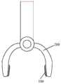
图3为一个实施例中机械手的结构示意图;3 is a schematic structural diagram of a manipulator in one embodiment;
图4为一个实施例中触觉传感器受力结构示意图。FIG. 4 is a schematic diagram of a force-bearing structure of a tactile sensor in an embodiment.
具体实施方式Detailed ways
为了使本领域的技术人员更好地理解本申请中的技术方案,下面将结合本申请实施例中的附图对本申请实施例中的技术方案进行清楚、完整地描述,显然,所描述的实施例仅仅是本申请的一部分实施例,而不是全部的实施例。基于本申请中的实施例,本领域普通技术人员在没有做出创造性劳动前提下所获得的所有其他实施例,都属于本申请保护的范围。In order for those skilled in the art to better understand the technical solutions in the present application, the technical solutions in the embodiments of the present application will be clearly and completely described below with reference to the drawings in the embodiments of the present application. Obviously, the described implementation The examples are only some of the embodiments of the present application, but not all of the embodiments. Based on the embodiments in the present application, all other embodiments obtained by those of ordinary skill in the art without creative efforts shall fall within the protection scope of the present application.
需要说明的是,当元件被称为“固定于”或“设置于”另一个元件上,它可以直接在另一个元件上或者间接设置在另一个元件上;当一个元件被称为是“连接于”另一个元件,它可以是直接连接到另一个元件或间接连接至另一个元件上。It should be noted that when an element is referred to as being "fixed" or "disposed on" another element, it can be directly or indirectly disposed on the other element; when an element is referred to as being "connected" "to" another element, it may be directly connected to another element or indirectly connected to another element.
需要理解的是,术语“长度”、“宽度”、“上”、下”、“前”、“后”、“左”、“右”、“竖直”、“水平”、“顶”、“底”“内”、“外”等指示的方位或位置关系为基于附图所示的方位或位置关系,仅是为了便于描述本申请和简化描述,而不是指示或暗示所指的装置或元件必须具有特定的方位、以特定的方位构造和操作,因此不能理解为对本申请的限制。It is to be understood that the terms "length", "width", "upper", "lower", "front", "rear", "left", "right", "vertical", "horizontal", "top", The orientation or positional relationship indicated by "bottom", "inner", "outer", etc. is based on the orientation or positional relationship shown in the drawings, and is only for the convenience of describing the present application and simplifying the description, rather than indicating or implying the indicated device or Elements must have a particular orientation, be constructed and operate in a particular orientation and are therefore not to be construed as limitations on this application.
此外,术语“第一”、“第二”仅用于描述目的,而不能理解为指示或暗示相对重要性或者隐含指明所指示的技术特征的数量。由此,限定有“第一”、“第二”的特征可以明示或者隐含地包括一个或者更多个该特征。在本申请的描述中,“多个”、“若干个”的含义是两个或两个以上,除非另有明确具体的限定。In addition, the terms "first" and "second" are only used for descriptive purposes, and should not be construed as indicating or implying relative importance or implying the number of indicated technical features. Thus, a feature defined as "first", "second" may expressly or implicitly include one or more of that feature. In the description of the present application, "plurality" and "several" mean two or more, unless otherwise expressly and specifically defined.
须知,本说明书附图所绘示的结构、比例、大小等,均仅用以配合说明书所揭示的内容,以供熟悉此技术的人士了解与阅读,并非用以限定本申请可实施的限定条件,故不具技术上的实质意义,任何结构的修饰、比例关系的改变或大小的调整,在不影响本申请所能产生的功效及所能达成的目的下,均应仍落在本申请所揭示的技术内容得能涵盖的范围内。It should be noted that the structures, proportions, sizes, etc. shown in the drawings of this specification are only used to cooperate with the contents disclosed in the specification for the understanding and reading of those who are familiar with this technology, and are not used to limit the conditions that the application can implement. Therefore, it has no technical substantive significance. Any structural modification, proportional relationship change or size adjustment should still fall within the scope of the disclosure in this application, without affecting the effect that the application can produce and the purpose that can be achieved. The technical content must be able to cover the scope.
在一个实施例中,如图1和图2所示,提供了一种触觉传感器,所述的触觉传感器包括:柔性基片4、包埋于所述柔性基片4的微纳光纤和附着于所述柔性基片4表面的仿指纹结构贴片;其中,所述柔性基片4的折射率低于所述微纳光纤的折射率,所述仿指纹结构贴片的硬度高于所述柔性基片4。In one embodiment, as shown in FIG. 1 and FIG. 2, a tactile sensor is provided, and the tactile sensor includes: a
其中,微纳光纤是一种直径与传输光波长接近甚至更小的新型光纤,具有光场约束力强,倏逝场比例大,弯曲损耗小等光学传输特性。微纳光纤外围的倏逝场对所处环境的微弱变化十分敏感,在制备灵敏度高、响应时间短、抗疲劳性好和器件功耗低的高性能触觉传感器方面具有突出优势。Among them, micro-nano fiber is a new type of optical fiber with a diameter close to or even smaller than the wavelength of the transmitted light. The evanescent field at the periphery of the micro-nano fiber is very sensitive to weak changes in the environment, and has outstanding advantages in the preparation of high-performance tactile sensors with high sensitivity, short response time, good fatigue resistance and low device power consumption.
其中,将微纳光纤封装在柔性基片内部之后,将具有仿指纹结构的仿指纹结构贴片粘附在柔性基片表面并位于微纳光纤拉锥过渡区2的正上方,传感位置位于仿指纹结构贴片处,输入光通过微纳光纤的一端输入光纤,通过拉锥过渡区,再由微纳光纤的另一端输出至探测器;当仿指纹结构贴片受到如剪切力的外力时(如图4所示横向箭头方向的力),所示外力将通过仿指纹结构贴片传导至底部的微纳光纤(如图4所示竖向箭头方向的力),引发微纳光纤微小弯曲,弯曲导致光线的损耗增强,因而输出光强减小,故通过建立光强变化与角度之间的一一对应关系,实现实时触觉传感。Among them, after the micro-nano fiber is encapsulated inside the flexible substrate, the imitation fingerprint structure patch with the imitation fingerprint structure is attached to the surface of the flexible substrate and is located just above the micro-nano fiber
本实施例中,触觉传感器不仅能够检测竖向的压力,还能检测横向的剪切力,能够实现对滑觉的检测;同时,仿指纹结构贴片作为外界力的传导介质,相对较高的机械硬度可以起到信号放大的作用,避免了力学信号在传导至微纳光纤之前被柔软的材料吸收,增强了触觉传感器的灵敏度。In this embodiment, the tactile sensor can detect not only the vertical pressure, but also the lateral shearing force, which can realize the detection of sliding sensation; at the same time, the imitation fingerprint structure patch, as the conduction medium of external force, has a relatively high The mechanical stiffness can play the role of signal amplification, avoid the mechanical signal being absorbed by the soft material before being transmitted to the micro-nano fiber, and enhance the sensitivity of the tactile sensor.
在其中一个实施例中,如图1和图2所示,所述的触觉传感器还包括:与所述微纳光纤的第一端11连接的光源7,与所述微纳光纤的第二端12连接的探测器8。In one of the embodiments, as shown in FIG. 1 and FIG. 2 , the tactile sensor further includes: a
其中,微纳光纤的两端分别于光源7和探测器8,光源7用于向微纳光纤输入光,探测器8从微纳光纤的另一端接收光,通过光通过微纳光纤之后减少的强度,来判断微纳光纤受力的情况,从而判断触觉传感器的受力情况。Among them, the two ends of the micro-nano fiber are respectively connected to the
其中,所述光源7为贴片LED,所述探测器8为CCD芯片。当然,光源7也可为白炽灯光、激光,探测器8也可为其它将光信号转换成电信号的处理装置。Wherein, the
其中,当仿指纹结构贴片受到压力、剪切力时,指纹结构会将各个方向的受力分解出向下的压力,从而导致微纳光纤发生微小形变,通过检测输出光光强的降低,建立信号光减弱幅度与力的关系映射,通过对比即可获取外力信息。Among them, when the imitation fingerprint structure patch is subjected to pressure and shear force, the fingerprint structure will decompose the force in all directions into downward pressure, which will cause micro-nano fiber to deform slightly. By detecting the decrease in the output light intensity, the establishment of The relationship between the attenuation amplitude of the signal light and the force is mapped, and the external force information can be obtained through comparison.
在其中一个实施例中,所述柔性基片的折射率高于空气的折射率。本实施例中,柔性基片折射率的设计能够保证微纳光纤传输损耗较小的同时,在光纤外围有较高比例的倏逝场存在,以确保触觉传感器的高灵敏度。In one embodiment, the index of refraction of the flexible substrate is higher than that of air. In this embodiment, the design of the refractive index of the flexible substrate can ensure that the transmission loss of the micro-nano optical fiber is small, and at the same time, there is a high proportion of evanescent field at the periphery of the optical fiber, so as to ensure the high sensitivity of the tactile sensor.
在其中一个实施例中,所述微纳光纤包括:未拉伸光纤1、拉锥过渡区2和光纤拉锥的拉伸部分3,所述光纤拉锥的拉伸部分3的两端为拉锥过渡区2,所述拉锥过渡区2外侧为未拉伸光纤1,所述光纤拉锥的拉伸部分3为传感区域。In one embodiment, the micro-nano optical fiber comprises: an unstretched
其中,柔性基片4的材料可为聚二甲基硅氧烷(PDMS)。标准通信光纤作为微纳光纤制备的原材料,将弹性树脂(Elastic Resin)作为制作仿指纹结构贴片的材料。The material of the
例如,将聚二甲基硅氧烷(PDMS)预聚体A与B按照10:1比例充分混合,除去气泡后均匀地涂抹在载玻片表面,构成柔性基片的衬底部分;将标准通讯光纤剥去涂覆层2~3cm,用氢气火焰加热剥去涂覆层的裸光纤,并将裸光纤尾端向两侧拉伸获取光纤拉锥的拉伸部分3,将拉制的光纤拉锥的拉伸部分3置于柔性基片的衬底部分,在光纤表面再次覆盖一层聚二甲基硅氧烷(PDMS)并加热固化,从而将光纤拉锥部分封装在柔性基片内部。For example, the polydimethylsiloxane (PDMS) prepolymers A and B are thoroughly mixed in a ratio of 10:1, and the air bubbles are removed and evenly spread on the surface of the glass slide to form the substrate part of the flexible substrate; The communication optical fiber is stripped of the coating layer for 2-3 cm, and the stripped bare optical fiber is heated with a hydrogen flame, and the tail end of the bare optical fiber is stretched to both sides to obtain the
在其中一个实施例中,所述仿指纹结构贴片包括弹性贴片基底5和仿指纹突起6,所述弹性贴片基底5下侧附着于所述柔性基片4表面,所述弹性贴片基底5上侧设置仿指纹突起6。In one embodiment, the imitation fingerprint structure patch includes an
其中,所述弹性贴片基底5厚度小于或等于1毫米,能够保证触觉传感器对压力和剪切力的检测。Wherein, the thickness of the
在其中一个实施例中,所述仿指纹突起6为多个;每个所述仿指纹突起6的高度大于0毫米并小于5毫米,且宽度大于0毫米并小于5毫米;两个所述仿指纹突起6之间的间距大于0毫米并小于10毫米。本实施例中,通过设置多个仿指纹凸起,并且对仿指纹凸起设置合适的尺寸,能够保证对剪切力的检测,并且受力的仿指纹凸起越多,受力的强度越大,根据受力的仿指纹凸起的数目与受力的强度的关系,可以检测物体在触觉传感器的滑动趋势。In one embodiment, there are multiple
其中,所述仿指纹结构贴片为树脂材料一体成型结构。其中,利用弹性树脂材料通过3D打印的方式打印仿指纹结构贴片。Wherein, the imitation fingerprint structure patch is an integral molding structure of resin material. Among them, the imitation fingerprint structure patch is printed by 3D printing with elastic resin material.
在其中一个实施例中,所述柔性基片4与所述仿指纹结构贴片底部通过硅橡胶进行粘合。In one embodiment, the
在一个实施例中,如图3所示,提供了一种机械手,包括:上述实施例中所述的触觉传感器100和机械手手指200,所述触觉传感器100设置于所述机械手手指200的夹持部。In one embodiment, as shown in FIG. 3 , a manipulator is provided, including: the
其中,所述机械手手指200在夹持物体时,触觉传感器100的仿指纹结构贴片与物体接触,检测夹持物体的压力和物体向下滑动的剪切力,通过触觉传感器100能够检测物体的滑动趋势,从而相适应的增加夹持物体的压力来保证物体正好不滑动,能够适用于柔性物体、易碎物品的夹持,例如,可以通过带有触觉传感器的机械手捡果冻、拿玻璃杯。Wherein, when the
上述实施例中触觉传感器,相比于电学传感器,基于光信号检测的光学传感器具有良好的电气安全性、抗电磁干扰能力、极短的响应时间和高灵敏度以及高信号分辨率。其中,通过微纳光纤制作的触觉传感器,其体积小、重量轻、结构紧凑、灵敏度高,可以应用于各种各样的机械手。The tactile sensor in the above embodiment, compared with the electrical sensor, the optical sensor based on light signal detection has good electrical safety, anti-electromagnetic interference capability, extremely short response time, high sensitivity and high signal resolution. Among them, the tactile sensor made of micro-nano fiber has small size, light weight, compact structure and high sensitivity, and can be applied to various manipulators.
以上所述实施例的各技术特征可以进行任意的组合,为使描述简洁,未对上述实施例中的各个技术特征所有可能的组合都进行描述,然而,只要这些技术特征的组合不存在矛盾,都应当认为是本说明书记载的范围。The technical features of the above-described embodiments can be combined arbitrarily. For the sake of brevity, all possible combinations of the technical features in the above-described embodiments are not described. However, as long as there is no contradiction between the combinations of these technical features, All should be regarded as the scope described in this specification.
以上所述实施例仅表达了本发明的几种实施方式,其描述较为具体和详细,但并不能因此而理解为对发明专利范围的限制。应当指出的是,对于本领域的普通技术人员来说,在不脱离本发明构思的前提下,还可以做出若干变形和改进,这些都属于本发明的保护范围。因此,本发明专利的保护范围应以所附权利要求为准。The above-mentioned embodiments only represent several embodiments of the present invention, and the descriptions thereof are specific and detailed, but should not be construed as a limitation on the scope of the invention patent. It should be pointed out that for those skilled in the art, without departing from the concept of the present invention, several modifications and improvements can be made, which all belong to the protection scope of the present invention. Therefore, the protection scope of the patent of the present invention shall be subject to the appended claims.
Claims (10)
Priority Applications (1)
| Application Number | Priority Date | Filing Date | Title |
|---|---|---|---|
| CN202010985284.XACN112092018B (en) | 2020-09-18 | 2020-09-18 | Touch sensor and manipulator |
Applications Claiming Priority (1)
| Application Number | Priority Date | Filing Date | Title |
|---|---|---|---|
| CN202010985284.XACN112092018B (en) | 2020-09-18 | 2020-09-18 | Touch sensor and manipulator |
Publications (2)
| Publication Number | Publication Date |
|---|---|
| CN112092018Atrue CN112092018A (en) | 2020-12-18 |
| CN112092018B CN112092018B (en) | 2022-03-01 |
Family
ID=73759762
Family Applications (1)
| Application Number | Title | Priority Date | Filing Date |
|---|---|---|---|
| CN202010985284.XAActiveCN112092018B (en) | 2020-09-18 | 2020-09-18 | Touch sensor and manipulator |
Country Status (1)
| Country | Link |
|---|---|
| CN (1) | CN112092018B (en) |
Cited By (4)
| Publication number | Priority date | Publication date | Assignee | Title |
|---|---|---|---|---|
| CN113503917A (en)* | 2021-07-05 | 2021-10-15 | 之江实验室 | Flexible temperature and pressure sensor based on micro-nano optical fiber |
| CN113601538A (en)* | 2021-07-30 | 2021-11-05 | 之江实验室 | Optical waveguide type soft optical driver based on micro-nano optical fiber |
| CN116642612A (en)* | 2023-07-27 | 2023-08-25 | 之江实验室 | Sensor, preparation method thereof, manipulator and robot |
| CN117451228A (en)* | 2023-10-26 | 2024-01-26 | 重庆理工大学 | MNF flexible tactile sensing system simulating fingertip skin microstructure and manufacturing method |
Citations (8)
| Publication number | Priority date | Publication date | Assignee | Title |
|---|---|---|---|---|
| CN1067503A (en)* | 1991-06-05 | 1992-12-30 | 北京理工大学 | Flexible optical fibre array tactile sensor |
| JP2006349461A (en)* | 2005-06-15 | 2006-12-28 | Sharp Corp | RFID-type tactile sensor and RFID-type tactile sensor input device |
| CN104034459A (en)* | 2014-06-27 | 2014-09-10 | 大连理工大学 | Optical flexible two-dimensional tangential force touch sensor |
| CN206192550U (en)* | 2016-11-23 | 2017-05-24 | 浙江大学 | A capacitive tactile sensor with an array of patterned microstructures |
| CN107014411A (en)* | 2017-04-05 | 2017-08-04 | 浙江大学 | A kind of flexible micro-nano fiber angle sensor chip and sensor and preparation method |
| CN108015745A (en)* | 2017-11-27 | 2018-05-11 | 清华大学 | A kind of flexible manipulator based on marmem |
| JP2019184434A (en)* | 2018-04-11 | 2019-10-24 | 三菱ケミカル株式会社 | Displacement sensor, press button switch, vehicle impact detector, tactile sensor, and emergency stop switch |
| CN111229345A (en)* | 2020-01-22 | 2020-06-05 | 浙江大学 | Micro-fluidic chip flow velocity sensor based on micro-nano optical fiber |
- 2020
- 2020-09-18CNCN202010985284.XApatent/CN112092018B/enactiveActive
Patent Citations (8)
| Publication number | Priority date | Publication date | Assignee | Title |
|---|---|---|---|---|
| CN1067503A (en)* | 1991-06-05 | 1992-12-30 | 北京理工大学 | Flexible optical fibre array tactile sensor |
| JP2006349461A (en)* | 2005-06-15 | 2006-12-28 | Sharp Corp | RFID-type tactile sensor and RFID-type tactile sensor input device |
| CN104034459A (en)* | 2014-06-27 | 2014-09-10 | 大连理工大学 | Optical flexible two-dimensional tangential force touch sensor |
| CN206192550U (en)* | 2016-11-23 | 2017-05-24 | 浙江大学 | A capacitive tactile sensor with an array of patterned microstructures |
| CN107014411A (en)* | 2017-04-05 | 2017-08-04 | 浙江大学 | A kind of flexible micro-nano fiber angle sensor chip and sensor and preparation method |
| CN108015745A (en)* | 2017-11-27 | 2018-05-11 | 清华大学 | A kind of flexible manipulator based on marmem |
| JP2019184434A (en)* | 2018-04-11 | 2019-10-24 | 三菱ケミカル株式会社 | Displacement sensor, press button switch, vehicle impact detector, tactile sensor, and emergency stop switch |
| CN111229345A (en)* | 2020-01-22 | 2020-06-05 | 浙江大学 | Micro-fluidic chip flow velocity sensor based on micro-nano optical fiber |
Non-Patent Citations (1)
| Title |
|---|
| 包玉龙等: "触觉传感器研究现状与展望", 《装备制造技术》* |
Cited By (5)
| Publication number | Priority date | Publication date | Assignee | Title |
|---|---|---|---|---|
| CN113503917A (en)* | 2021-07-05 | 2021-10-15 | 之江实验室 | Flexible temperature and pressure sensor based on micro-nano optical fiber |
| CN113601538A (en)* | 2021-07-30 | 2021-11-05 | 之江实验室 | Optical waveguide type soft optical driver based on micro-nano optical fiber |
| CN116642612A (en)* | 2023-07-27 | 2023-08-25 | 之江实验室 | Sensor, preparation method thereof, manipulator and robot |
| CN116642612B (en)* | 2023-07-27 | 2024-01-09 | 之江实验室 | Sensor, preparation method thereof, manipulator and robot |
| CN117451228A (en)* | 2023-10-26 | 2024-01-26 | 重庆理工大学 | MNF flexible tactile sensing system simulating fingertip skin microstructure and manufacturing method |
Also Published As
| Publication number | Publication date |
|---|---|
| CN112092018B (en) | 2022-03-01 |
Similar Documents
| Publication | Publication Date | Title |
|---|---|---|
| CN112092018A (en) | Touch sensor and manipulator | |
| Kim et al. | Heterogeneous sensing in a multifunctional soft sensor for human-robot interfaces | |
| Ma et al. | Optical micro/nano fibers enabled smart textiles for human–machine interface | |
| CN111656235A (en) | Waveguides and Waveguide-Based Sensors | |
| CN102207415B (en) | Conductive-rubber-based flexible array clip pressure sensor and manufacturing method | |
| CN107588872B (en) | Three-dimensional force-flexible tactile sensor based on conductive fabric | |
| CN110082010A (en) | Flexible touch sensation sensor array and array scanning system applied to it | |
| CN112014022A (en) | Photoelectric fusion touch sensor based on micro-nano optical fiber | |
| CN205940446U (en) | Transparent strain sensor located in visible area of electronic device and electronic device | |
| CN113503917B (en) | Flexible temperature and pressure sensor based on micro-nano optical fiber | |
| WO2012173420A2 (en) | Wired electrode for a touch screen panel | |
| CN106625729A (en) | Humanoid type mechanical finger with perceptive functions of temperature and touch force | |
| CN108161994A (en) | A kind of multi-modal tactile sensor | |
| CN111609953A (en) | A fully flexible capacitive three-dimensional force tactile sensor based on spherical curved electrodes | |
| CN113598754A (en) | Wearable device, and human body motion detection method and device | |
| CN108444620A (en) | A kind of multiple stage array pressure sensor of same laminar | |
| Hu et al. | Polymer-based optical waveguide tactile sensing method for 3-D surfaces | |
| CN112229553B (en) | A flexible tactile sensor based on light attenuation, array and preparation method thereof | |
| KR20090008778A (en) | Tactile sensor using micro-bending characteristics of optical fiber, manufacturing method and distributed load measuring device using the same | |
| CN108549504A (en) | Touch-control sensing substrate and touch device | |
| CN105870070B (en) | An optical sensor package structure and its integrated board | |
| CN106323512B (en) | Method for packaging diversified piezoelectric sensors by using heat-sensitive hydrophobic elastic high polymer material | |
| Yang et al. | Liquid Lens‐Based Optical Tactile Sensor with a Touch‐Sensing Separable Structure | |
| CN109176572B (en) | Sliding detection probe for fingertip of robot and working method | |
| CN206373923U (en) | A kind of apery type mechanical finger with temperature and tactile force sensing function |
Legal Events
| Date | Code | Title | Description |
|---|---|---|---|
| PB01 | Publication | ||
| PB01 | Publication | ||
| SE01 | Entry into force of request for substantive examination | ||
| SE01 | Entry into force of request for substantive examination | ||
| CB03 | Change of inventor or designer information | Inventor after:Zhang Lei Inventor after:Pan Jing Inventor after:Xu Yan Inventor before:Xu Yan Inventor before:Pan Jing Inventor before:Zhang Lei | |
| CB03 | Change of inventor or designer information | ||
| GR01 | Patent grant | ||
| GR01 | Patent grant |