CN112090388B - Continuous flow reactor and application thereof in chemical reaction and synthesis - Google Patents
Continuous flow reactor and application thereof in chemical reaction and synthesisDownload PDFInfo
- Publication number
- CN112090388B CN112090388BCN202010930765.0ACN202010930765ACN112090388BCN 112090388 BCN112090388 BCN 112090388BCN 202010930765 ACN202010930765 ACN 202010930765ACN 112090388 BCN112090388 BCN 112090388B
- Authority
- CN
- China
- Prior art keywords
- tube bundle
- reaction tube
- reaction
- continuous flow
- head
- Prior art date
- Legal status (The legal status is an assumption and is not a legal conclusion. Google has not performed a legal analysis and makes no representation as to the accuracy of the status listed.)
- Expired - Fee Related
Links
Images


Classifications
- B—PERFORMING OPERATIONS; TRANSPORTING
- B01—PHYSICAL OR CHEMICAL PROCESSES OR APPARATUS IN GENERAL
- B01J—CHEMICAL OR PHYSICAL PROCESSES, e.g. CATALYSIS OR COLLOID CHEMISTRY; THEIR RELEVANT APPARATUS
- B01J19/00—Chemical, physical or physico-chemical processes in general; Their relevant apparatus
- B01J19/24—Stationary reactors without moving elements inside
- B01J19/2415—Tubular reactors
- B01J19/242—Tubular reactors in series
- B—PERFORMING OPERATIONS; TRANSPORTING
- B01—PHYSICAL OR CHEMICAL PROCESSES OR APPARATUS IN GENERAL
- B01J—CHEMICAL OR PHYSICAL PROCESSES, e.g. CATALYSIS OR COLLOID CHEMISTRY; THEIR RELEVANT APPARATUS
- B01J2219/00—Chemical, physical or physico-chemical processes in general; Their relevant apparatus
- B01J2219/00049—Controlling or regulating processes
- B01J2219/00051—Controlling the temperature
- B01J2219/00074—Controlling the temperature by indirect heating or cooling employing heat exchange fluids
- B01J2219/00087—Controlling the temperature by indirect heating or cooling employing heat exchange fluids with heat exchange elements outside the reactor
Landscapes
- Chemical & Material Sciences (AREA)
- Organic Chemistry (AREA)
- Chemical Kinetics & Catalysis (AREA)
- Physical Or Chemical Processes And Apparatus (AREA)
Abstract
Translated fromChinese
Description
Translated fromChinese技术领域technical field
本发明涉及化学反应技术领域,具体涉及一种连续流反应器及其在化学反应和合成中的应用。The invention relates to the technical field of chemical reactions, in particular to a continuous flow reactor and its application in chemical reactions and synthesis.
背景技术Background technique
连续流微通道反应器具有空间上特征尺寸小的特点,在很多方面具有优异的性能,如比表面积大,传质和传热效率高,能够精确控制反应时间、温度等条件,以及绿色安全生产等等。目前精细化工领域使用最广泛的反应器是搅拌釜,采用分批式进料,辅助操作繁琐,换热效率低下,反应器放大难度高。若使用连续流反应器可以避免传统搅拌釜换热能力差,反应器体积大等缺点,实现化工产品的连续化生产,显著提高生产效率和安全性能。Continuous flow microchannel reactors have the characteristics of small spatial characteristic size and excellent performance in many aspects, such as large specific surface area, high mass and heat transfer efficiency, accurate control of reaction time, temperature and other conditions, as well as green and safe production and many more. At present, the most widely used reactor in the field of fine chemical industry is the stirred tank, which adopts batch feeding, complicated auxiliary operation, low heat exchange efficiency, and high difficulty in scaling up the reactor. If the continuous flow reactor is used, the disadvantages of the traditional stirred tank such as poor heat exchange capacity and large reactor volume can be avoided, the continuous production of chemical products can be realized, and the production efficiency and safety performance can be significantly improved.
公开号为CN111434377A的专利说明书公开了一种盘管微通道反应器,反应器中含有支撑管和环绕该支撑管的微通道,微通道的内部设置有流体再分配构件,构件为椎体结构,使得流体由椎体尖端流出并进入所述微通道的下游,可以实现多股相溶或不相溶的多相原料混合液进行有效的混合并进行长时间的化学反应,进而同时提高产品的选择性和原料转化率。The patent specification with publication number CN111434377A discloses a coiled tube microchannel reactor. The reactor contains a support tube and a microchannel surrounding the support tube. The interior of the microchannel is provided with a fluid redistribution member, and the member is a vertebral body structure. The fluid flows out from the tip of the vertebral body and enters the downstream of the microchannel, which can realize the effective mixing of multiple compatible or immiscible multiphase raw material mixtures and carry out a long-term chemical reaction, thereby improving the selection of products at the same time. properties and raw material conversion.
公告号为CN208641841U的专利说明书公开了一种基于3D打印制造的多孔道微反应器,多孔微通道为多个均匀分布连续通道,截面为圆形,每个多孔通道形状为蛇形,每层中25个首尾相连的连续多孔通道构成锯齿形,使混合流体更容易形成紊流,对流扩散系数更高。使用该反应器进行金属钯、铂萃取,可实现11.55L/h的原料液处理量。但该反应器没有设置换热结构,近似于绝热反应器,不适用于热效应强的化学反应体系。The patent specification with the announcement number CN208641841U discloses a multi-channel microreactor manufactured based on 3D printing. The porous microchannel is a plurality of uniformly distributed continuous channels, the cross section is circular, and the shape of each porous channel is serpentine. The 25 continuous porous channels connected end to end form a zigzag shape, which makes it easier for the mixed fluid to form turbulent flow and has a higher convective diffusion coefficient. Using this reactor for extraction of metal palladium and platinum can achieve a throughput of 11.55L/h of raw material liquid. However, the reactor does not have a heat exchange structure, which is similar to an adiabatic reactor and is not suitable for chemical reaction systems with strong thermal effects.
公告号为CN107261997B的专利说明书公开了一种适用于液液多相反应的微通道反应器,微通道由套管环隙形成,内管由膜材料构成,分散相通过膜后以微乳液滴的形式均匀分散进入连续相中,并流接触,液液之间的相界面比一般反应器增大10倍以上,并且可以通过调节膜结构以控制微乳液滴尺寸,特别适用于高粘度液体参与的化学反应体系。The patent specification with the publication number CN107261997B discloses a microchannel reactor suitable for liquid-liquid multiphase reaction. The microchannel is formed by the casing annular gap, the inner tube is composed of membrane material, and the dispersed phase passes through the membrane. The form is uniformly dispersed into the continuous phase, and the co-current contact, the phase interface between the liquid and the liquid is more than 10 times larger than that of the general reactor, and the size of the microemulsion droplet can be controlled by adjusting the membrane structure, especially suitable for high viscosity liquid participation. chemical reaction system.
目前大部分连续微流通道反应器由于尺寸限制,持液量小,只能适用于小处理量或快速反应,因此,有必要设计一种适用于大处理量,更长反应停留时间的连续流反应器,拓展反应器适用范围,提高生产效率,降低设备成本。At present, most of the continuous microfluidic channel reactors are only suitable for small processing capacity or rapid reaction due to their size limitation and small liquid holding capacity. Therefore, it is necessary to design a continuous flow reactor suitable for large processing capacity and longer reaction residence time. The reactor can expand the scope of application of the reactor, improve the production efficiency and reduce the equipment cost.
发明内容SUMMARY OF THE INVENTION
本发明提供了一种连续流反应器,可保证不同进料流股快速混合,反应停留时间可以达到分钟级,特别适用于连续化操作的精细化学品合成反应,显著提高了生产效率和安全性能。The invention provides a continuous flow reactor, which can ensure the rapid mixing of different feed streams, and the reaction residence time can reach the minute level, which is especially suitable for the synthesis reaction of fine chemicals in continuous operation, and significantly improves the production efficiency and safety performance. .
一种连续流反应器,包括:A continuous flow reactor comprising:
反应管束,由若干六角直管沿6个外壁面法线方向阵列形成,相邻六角直管间通过导热翅片连接,管内填充有静态混合器;所述六角直管横截面为正六边形,直管轴向两端各设置一个开口,相邻两六角直管间通过开口互相连接;所述静态混合器由若干左、右螺旋型的叶片交替排列组成,相邻两叶片首尾存在交叉角;The reaction tube bundle is formed by a plurality of hexagonal straight tubes arrayed along the normal direction of 6 outer walls, adjacent hexagonal straight tubes are connected by heat conducting fins, and the tubes are filled with static mixers; the cross-section of the hexagonal straight tubes is a regular hexagon, An opening is provided at both ends of the straight pipe in the axial direction, and two adjacent hexagonal straight pipes are connected to each other through the opening; the static mixer is composed of a plurality of left and right helical blades arranged alternately, and there is a cross angle at the head and tail of the two adjacent blades;
固定板,为沿所述反应管束轴向拉伸的板状结构,设于所述反应管束轴向两端,用于固定所述反应管束各六角直管相对位置;The fixing plate is a plate-like structure stretched along the axial direction of the reaction tube bundle, and is arranged at both ends of the reaction tube bundle in the axial direction, and is used for fixing the relative positions of the hexagonal straight tubes of the reaction tube bundle;
轴向封头,为沿所述反应管束轴向拉伸的板状结构,用于封闭所述反应管束轴向两端开口;The axial head is a plate-like structure stretched along the axial direction of the reaction tube bundle, and is used to close the openings at both ends of the reaction tube bundle in the axial direction;
横向封头,用于封闭所述反应管束横向两侧;a lateral head, used to close both lateral sides of the reaction tube bundle;
至少一个进料口,位于所述反应管束第一根六角直管上,与横向封头开口相连;At least one feed port is located on the first hexagonal straight pipe of the reaction tube bundle and is connected to the opening of the transverse head;
出料口,位于所述反应管束最后一根六角直管上,与横向封头开口相连;The discharge port is located on the last hexagonal straight tube of the reaction tube bundle, and is connected with the opening of the transverse head;
网状支撑结构,设置于所述反应管束纵向两侧;a mesh support structure, arranged on both sides of the reaction tube bundle in the longitudinal direction;
分布器,紧贴网状支撑结构外侧;Distributor, close to the outside of the mesh support structure;
换热介质封头,紧贴分布器腔体外侧。The heat exchange medium sealing head is close to the outside of the distributor cavity.
具体地:specifically:
所述六角直管,横截面为正六边形,轴向两端的壁面各设置有一个矩形开口,两开口所在壁面处于六边形的相对位置,相邻两根六角直管对应开口间形成一根短管,所述短管成为相邻两根六角直管的连接管。The hexagonal straight pipe has a regular hexagonal cross-section, and the wall surfaces at both ends of the axial direction are each provided with a rectangular opening, and the wall surfaces where the two openings are located are in hexagonal relative positions. A short pipe, the short pipe becomes the connecting pipe of two adjacent hexagonal straight pipes.
所述导热翅片由若干长方体排列组成,垂直分布于所述六角直管外壁面,两端分别与相邻两根六角直管外壁面连接,使得若干六角直管连接为一个反应管束整体。每个导热翅片均设置有两个三棱柱形加强筋,分别位于相邻两根六角直管的外壁面上。The heat-conducting fins are composed of a number of rectangular parallelepipeds, which are vertically distributed on the outer wall of the hexagonal straight tube, and the two ends are respectively connected to the outer wall of two adjacent hexagonal straight tubes, so that the hexagonal straight tubes are connected as a whole reaction tube bundle. Each of the heat-conducting fins is provided with two triangular prism-shaped reinforcing ribs, which are respectively located on the outer wall surfaces of the two adjacent hexagonal straight pipes.
所述叶片的横截面为矩形,由所述矩形按照一定扭转角、旋向和螺距扫描形成。所述叶片表面优选开有若干贯穿孔。叶片一端可设置有三棱柱形加强筋,紧贴六角直管内壁。The cross section of the blade is a rectangle, which is formed by scanning the rectangle according to a certain twist angle, rotation direction and pitch. The blade surface is preferably provided with several through holes. One end of the blade can be provided with a triangular prism-shaped reinforcing rib, which is close to the inner wall of the hexagonal straight pipe.
所述扭转角优选为90~180°。The twist angle is preferably 90 to 180°.
所述叶片的长径比优选为1~4:1,进一步优选为1.5~3:1。The aspect ratio of the blade is preferably 1 to 4:1, more preferably 1.5 to 3:1.
所述叶片上贯穿孔的数量优选为1~10个,进一步优选为1~6个,贯穿孔尺寸优选为1~8mm,进一步优选为2~5mm。The number of through holes on the blade is preferably 1 to 10, more preferably 1 to 6, and the size of the through holes is preferably 1 to 8 mm, more preferably 2 to 5 mm.
所述固定板上开有与六角直管数量相等的正六边形小孔,小孔轮廓和尺寸与所述六角直管外壁横截面相同,反应管束从小孔中穿过,两个固定板外侧分别与反应管束两端处于同一平面。The fixed plate is provided with regular hexagonal small holes equal to the number of hexagonal straight pipes, the outline and size of the small holes are the same as the cross-section of the outer wall of the hexagonal straight pipe, the reaction tube bundle passes through the small holes, and the outer sides of the two fixed plates are They are in the same plane with the two ends of the reaction tube bundle respectively.
所述轴向封头内侧面紧贴固定板外侧,同时也紧贴反应管束一端。The inner side of the axial head is close to the outside of the fixing plate, and also close to one end of the reaction tube bundle.
所述横向封头为矩形。The lateral head is rectangular.
所述反应管束,横向两侧被两个横向封头密封。横向封头与反应管束在结构上为一个整体,其中一侧的矩形封头上开有若干个进料口和一个出料口。The reaction tube bundle is sealed by two lateral heads on both lateral sides. The transverse head and the reaction tube bundle are structurally integrated, and the rectangular head on one side is provided with several feed ports and one discharge port.
所述进料口和出料口,内部与反应管束管程形成反应介质蛇形流动路径,外部连接反应介质进料和出料管线。The feed port and the discharge port form a serpentine flow path of the reaction medium internally with the tube side of the reaction tube bundle, and externally connect the feed and discharge pipelines of the reaction medium.
所述反应管束纵向两侧且所述固定板间设置有网状支撑结构,所述网状支撑结构外侧被换热介质分布器紧密贴合。A mesh-shaped support structure is arranged between the two longitudinal sides of the reaction tube bundle and between the fixed plates, and the outside of the mesh-shaped support structure is closely attached by the heat exchange medium distributor.
所述分布器为腔体结构,靠近所述反应管束一侧开有若干孔,远离反应管束一侧紧贴所述换热介质封头。The distributor is of a cavity structure, and a number of holes are opened on the side close to the reaction tube bundle, and the side away from the reaction tube bundle is close to the heat exchange medium seal head.
所述换热介质封头开孔,内侧与分布器腔体相连,外侧与换热介质进料管线或出料管线相连。换热介质封头、所述反应管束外壁和固定板内侧共同形成规整的换热介质流动路径。The heat exchange medium sealing head has an opening, the inner side is connected with the distributor cavity, and the outer side is connected with the heat exchange medium feed line or discharge line. The heat exchange medium head, the outer wall of the reaction tube bundle and the inner side of the fixed plate together form a regular heat exchange medium flow path.
本发明还提供了所述的连续流反应器在化学反应和合成领域中的应用。The invention also provides the application of the continuous flow reactor in the field of chemical reaction and synthesis.
使用本发明的连续流反应器进行化学反应时,反应料液可通过不同进料口进入第一根六角直管,在静态混合器的作用下,不同流股在在管内反复切割、分裂、合并,从而实现快速混合,管内反应介质到达第一根六角直管端头后通过短管进入下一根六角直管,如此反复直至管内反应介质到达最后一根六角直管末尾,最后从出料口流出。宏观上看,反应介质进入反应器后呈现蛇形往复流动,依次流经每一根六角直管,最后从出料口流出反应器。换热介质通过管线进入分布器,从分布器孔流入反应管束壳程,通过间壁传热与管内反应介质进行热交换,两流体错流换热,最后换热介质通过另一侧分布器流出反应器壳程。本发明通过管内填充静态混合器、管外设置导热翅片、构建反应介质的蛇形往复路径,强化了反应过程的传质、传热,实现连续化操作,反应停留时间达到分钟级,具有生产效率高和安全性能好的优点。When the continuous flow reactor of the present invention is used for chemical reaction, the reactant liquid can enter the first hexagonal straight pipe through different feed ports, and under the action of the static mixer, different streams are repeatedly cut, split and merged in the pipe. , so as to achieve rapid mixing, the reaction medium in the tube reaches the end of the first hexagonal straight tube and then enters the next hexagonal straight tube through the short tube, and so on until the reaction medium in the tube reaches the end of the last hexagonal straight tube, and finally from the discharge port outflow. From a macroscopic point of view, the reaction medium flows back and forth in a serpentine shape after entering the reactor, flows through each hexagonal straight pipe in turn, and finally flows out of the reactor from the discharge port. The heat exchange medium enters the distributor through the pipeline, flows into the shell side of the reaction tube bundle from the distributor hole, and exchanges heat with the reaction medium in the tube through the heat transfer of the partition wall. shell process. The invention strengthens the mass transfer and heat transfer in the reaction process by filling the static mixer in the tube, disposing the heat conducting fins outside the tube, and constructing the serpentine reciprocating path of the reaction medium, so as to realize continuous operation, the reaction residence time reaches the minute level, and the production The advantages of high efficiency and good safety performance.
所述反应管束壳程,是由反应管束正六边形外壁面形成的规整流道,壳程中导热翅片起支撑管束和壳程扰流作用,增大壳程换热系数和换热面积,提高了管内承压能力和控温精度。The shell side of the reaction tube bundle is a regular flow channel formed by the regular hexagonal outer wall of the reaction tube bundle, and the heat conduction fins in the shell side play the role of supporting the tube bundle and disturbing the flow of the shell side, increasing the heat transfer coefficient and heat transfer area of the shell side, The pressure bearing capacity and temperature control accuracy in the tube are improved.
作为优选,所述化学反应体系为液体均相反应或者不完全互溶的液液两相流反应。本发明的连续流反应器尤其适用于需要多点进料的反应体系。Preferably, the chemical reaction system is a liquid homogeneous reaction or an incompletely miscible liquid-liquid two-phase flow reaction. The continuous flow reactor of the present invention is particularly suitable for reaction systems requiring multiple feeds.
作为优选,所述连续流反应器可以并联或串联使用,可满足任意生产能力和1~10分钟内的反应停留时间要求。Preferably, the continuous flow reactors can be used in parallel or in series, and can meet the requirements of any production capacity and reaction residence time within 1 to 10 minutes.
所述连续流反应器可采用ABS树脂、PEEK、尼龙12、314不锈钢、316不锈钢、316L不锈钢、钛合金或哈氏合金等材料。The continuous flow reactor can be made of ABS resin, PEEK, nylon 12, 314 stainless steel, 316 stainless steel, 316L stainless steel, titanium alloy or Hastelloy and other materials.
所述六角直管内壁正六边形边长优选为1~20mm,进一步优选为2~10mm。The hexagonal side length of the inner wall of the hexagonal straight pipe is preferably 1-20 mm, more preferably 2-10 mm.
所述六角直管的长度优选为50~1000mm,进一步优选为150~500mm。The length of the hexagonal straight pipe is preferably 50 to 1000 mm, more preferably 150 to 500 mm.
本发明与现有技术相比,主要优点包括:反应介质流道内置静态混合器,对于均相反应可以实现多股物料的快速混合,增大反应转化率和选择性,对于液液两相流反应可以实现分散相的快速分散,增大两相接触面积,提高化学反应速率;反应管束间的串联结构,迫使反应介质在管程做蛇形往复流动,反应停留时间增加,反应原料转化率和目标产物选择性提高,单位反应器体积原料处理量增大;导热翅片起到壳程扰流和支撑反应管束的作用,强化壳程换热能力和增大反应管束结构的机械强度。Compared with the prior art, the main advantages of the present invention include: a static mixer is built in the flow channel of the reaction medium, which can realize rapid mixing of multiple materials for homogeneous reaction, and increase the reaction conversion rate and selectivity. The reaction can realize the rapid dispersion of the dispersed phase, increase the contact area of the two phases, and improve the chemical reaction rate; the series structure between the reaction tube bundles forces the reaction medium to serpentine reciprocating flow in the tube side, the reaction residence time increases, and the conversion rate of reaction raw materials and The selectivity of the target product is improved, and the raw material processing capacity per unit reactor volume is increased; the thermal conduction fins play the role of shell-side turbulence and support the reaction tube bundle, strengthen the shell-side heat transfer capacity and increase the mechanical strength of the reaction tube bundle structure.
附图说明Description of drawings
图1为实施例1的静态混合器的立体结构示意图;Fig. 1 is the three-dimensional structure schematic diagram of the static mixer of embodiment 1;
图2为实施例1的六角直管的立体结构示意图;Fig. 2 is the three-dimensional structure schematic diagram of the hexagonal straight pipe of embodiment 1;
图3为实施例1的反应管束的立体结构示意图;Fig. 3 is the three-dimensional structure schematic diagram of the reaction tube bundle of embodiment 1;
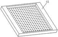
图4为实施例1的分布器的立体结构示意图;Fig. 4 is the three-dimensional structure schematic diagram of the distributor of embodiment 1;
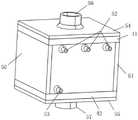
图5为实施例1的连续流反应器的立体结构示意图;Fig. 5 is the three-dimensional structure schematic diagram of the continuous flow reactor of embodiment 1;
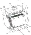
图6为实施例1的连续流反应器的拆分立体结构示意图;Fig. 6 is the split three-dimensional structure schematic diagram of the continuous flow reactor of embodiment 1;
图中:20-六角直管,21-导热翅片,22-静态混合器,30-反应管束,31-开口,32-固定板,33-固定板,41-分布器,50-轴向封头,51-轴向封头,52-进料口,53-出料口,54-换热介质封头,55-换热介质封头,56-换热介质进料管线,57-换热介质出料管线,61-网状支撑结构。In the picture: 20-hexagonal straight tube, 21-thermal conduction fin, 22-static mixer, 30-reaction tube bundle, 31-opening, 32-fixed plate, 33-fixed plate, 41-distributor, 50-axial seal Head, 51-Axial head, 52-Inlet, 53-Outlet, 54-Heat exchange medium head, 55-Heat exchange medium head, 56-Heat exchange medium feed line, 57-Heat exchange Media discharge line, 61-net support structure.
具体实施方式Detailed ways
下面结合附图及具体实施例,进一步阐述本发明。应理解,这些实施例仅用于说明本发明而不用于限制本发明的范围。下列实施例中未注明具体条件的操作方法,通常按照常规条件,或按照制造厂商所建议的条件。The present invention will be further described below with reference to the accompanying drawings and specific embodiments. It should be understood that these examples are only used to illustrate the present invention and not to limit the scope of the present invention. The operation method without specifying the specific conditions in the following examples is usually in accordance with the conventional conditions, or in accordance with the conditions suggested by the manufacturer.
实施例1Example 1
如图1-6所示,本实施例中的连续流反应器包括反应管束30,反应管束30由六角直管20沿六个外壁面法向阵列形成,数量为125根;每根直管两端均设置有开口31,相邻两根直管的开口间形成短管,使相邻两直管内部空间连通。相邻六角直管20间通过导热翅片21连接,除纵向最外侧一排直管,每根直管外壁面均设置有导热翅片21,数量为108个,最外侧一排直管每根直管的导热翅片数量为72个;每根直管内部填充有静态混合器22,静态混合器的立体结构如图1所示,由5个螺旋型叶片交替排列组成,相邻两叶片首尾交叉角为90°;5个螺旋型叶片均可视为矩形沿螺旋线扫描而成,扭转角180°,螺距30mm,厚度0.5mm,相邻两叶片的旋向相反,每个叶片上均开有6个圆形贯穿孔;反应管束轴向两端设置有两个固定板(32和33),固定板上开有125个正六边形小孔,小孔轮廓和尺寸与反应直管外壁横截面相同,反应管束从小孔中穿过,固定板外侧表面分别与反应管束两端头处于同一平面。As shown in FIGS. 1-6 , the continuous flow reactor in this embodiment includes a
反应管束30的轴向两端通过两个轴向封头(50和51)密封,使所有直管内部形成一个反应介质的流动路径;反应管束横向一侧开有三个进料口52和一个出料口53,进料口均与第一根六角直管相通,出料口与最后一根六角直管相通,从进料口到出料口之间是125根直管内部的串联通道。The two axial ends of the
反应管束30的纵向两侧设有网状支撑结构61,外侧再焊接有两个分布器(41和42),每个分布器靠近反应管束一侧开有256个圆孔,内部腔体深度10mm;分布器41远离反应管束一侧焊接有一个换热介质封头54,换热介质封头54中心开有圆孔,内部与分布器41腔体相连,外部与换热介质进料管线56相连;分布器42远离反应管束一侧焊接有一个换热介质封头55,换热介质封头中心开有圆孔,内部与分布器41腔体相连,外部与换热介质出料管线57相连。The longitudinal two sides of the
本实施例中,反应原料通过进料口52进入第一根六角直管后,在静态混合器作用下快速混合,管内到达第一根六角直管末尾后通过短管进入下一根六角直管,如此循环直至管内反应介质到达最后一根六角直管末尾,最后从出料口流出;换热介质从圆孔56进入分布器41腔体后通过圆孔实现均布,然后经过网状支撑结构61进入反应管束30壳程,在与反应管内反应流体错流换热后,流出反应管束进入分布器42腔体,最终通过圆孔57流入换热介质出料管线。In this embodiment, after the reaction raw materials enter the first hexagonal straight pipe through the feeding
应用例1Application example 1
使用实施例1的连续流反应器,以大豆油与甲醇为原料制备生物柴油为实施对象,大豆油通过计量泵后从任一进料口52进入反应器,溶解有催化剂氢氧化钠的甲醇溶液通过计量泵后从剩余两进料口52进入反应器,大豆油作为分散相在静态混合器22的作用下不断切割、分裂和拉伸,形成大量微乳液滴,与此同时与连续相进行反应。反应温度为65℃,反应压力为常压,原料甲醇和大豆油摩尔比为9:1,催化剂和原料重量比为1.5:100,反应停留时间为1min;反应产物通过倾析器后分别获得上层脂肪酸甲酯相和下层甘油相。使用石油醚对甘油相萃取后将石油醚与脂肪酸甲酯相合并,闪蒸除去石油醚和甲醇,再用饱和食盐水洗涤三次除去水溶性杂质,最后使用无水硫酸钠干燥后得到生物柴油产品,产率为94.8%。Using the continuous flow reactor of Example 1, taking soybean oil and methanol as raw materials to prepare biodiesel as an implementation object, soybean oil enters the reactor from any
对比例1Comparative Example 1
本对比例采用常见的钛合金搅拌釜,体积为2L,搅拌桨采用六叶片涡轮式搅拌桨,将0.1L大豆油与0.9L含有质量分数1.5%氢氧化钠的甲醇溶液投入反应釜,搅拌桨以500rpm转速搅拌,其他反应条件与实施例1相同,反应结束后,采用与实施例1相同的流程分离出产物生物柴油,产率仅为74.3%。In this comparative example, a common titanium alloy stirring tank is used, with a volume of 2L. The stirring paddle adopts a six-blade turbine stirring paddle. Stirring at 500 rpm, other reaction conditions were the same as in Example 1. After the reaction, the same process as in Example 1 was used to separate the product biodiesel, and the yield was only 74.3%.
对比例1与应用例1比较,产率较低,反应器体积较大,分批式操作繁琐。比较表明,实施例1中的连续流反应器对于液液两相流反应可以实现更高的生产效率。Comparing Comparative Example 1 with Application Example 1, the yield is lower, the volume of the reactor is larger, and the batch operation is cumbersome. The comparison shows that the continuous flow reactor in Example 1 can achieve higher production efficiency for the liquid-liquid two-phase flow reaction.
应用例2Application example 2
利用实施例1中所述连续流反应器,以糖精醇解制备邻甲酸甲酯苯磺酰胺为实施对象。Utilize the continuous flow reactor described in Example 1, take saccharin alcoholysis to prepare methyl o-formate benzenesulfonamide as the implementation object.
反应方程式如下:The reaction equation is as follows:

将糖精的甲醇溶液通过计量泵从任意两入口52注入反应器,浓硫酸也通过计量泵从剩余进料口52注入反应器,两股物料在静态混合器22作用下不断切割、分裂与合并,快速混合形成均一混合物,与此同时反应物充分反应。反应温度为60℃,反应压力为常压,糖精和甲醇的质量比为1:29,浓硫酸质量分数为98%,甲醇溶液和浓硫酸质量比为97:3,反应停留时间为1min;反应产物通过闪蒸除去甲醇后,用饱和碳酸氢钠溶液除去过量的酸,再进行过滤、饱和食盐水洗涤、无水硫酸钠干燥后,得到产物邻甲酸甲酯苯磺酰胺,产率为96.8%。The methanol solution of saccharin is injected into the reactor from any two
对比例2Comparative Example 2
本对比例采用对比例1相同的钛合金搅拌釜,将0.97L糖精的甲醇溶液与0.03L浓硫酸投入反应釜,反应物浓度与反应条件与应用例2相同,反应结束后,采用与应用例2相同的流程分离出产物邻甲酸甲酯苯磺酰胺,产率仅为83.4%。In this comparative example, the same titanium alloy stirred tank as in Comparative Example 1 was used, and 0.97L of methanol solution of saccharin and 0.03L of concentrated sulfuric acid were put into the reactor. The concentration of the reactants and the reaction conditions were the same as those in Application Example 2. 2 The product methyl o-formate benzene sulfonamide was isolated by the same process, and the yield was only 83.4%.
对比例2与应用例2比较,产率较低,反应器体积较大,分批式操作繁琐。比较表明,实施例1中的连续流反应器对于液体均相反应可以实现更高的生产效率。Comparing Comparative Example 2 with Application Example 2, the yield is lower, the volume of the reactor is larger, and the batch operation is cumbersome. The comparison shows that the continuous flow reactor in Example 1 can achieve higher production efficiency for the liquid homogeneous reaction.
此外应理解,在阅读了本发明的上述描述内容之后,本领域技术人员可以对本发明作各种改动或修改,这些等价形式同样落于本申请所附权利要求书所限定的范围。In addition, it should be understood that after reading the above description of the present invention, those skilled in the art can make various changes or modifications to the present invention, and these equivalent forms also fall within the scope defined by the appended claims of the present application.
Claims (6)
Translated fromChinesePriority Applications (1)
| Application Number | Priority Date | Filing Date | Title |
|---|---|---|---|
| CN202010930765.0ACN112090388B (en) | 2020-09-07 | 2020-09-07 | Continuous flow reactor and application thereof in chemical reaction and synthesis |
Applications Claiming Priority (1)
| Application Number | Priority Date | Filing Date | Title |
|---|---|---|---|
| CN202010930765.0ACN112090388B (en) | 2020-09-07 | 2020-09-07 | Continuous flow reactor and application thereof in chemical reaction and synthesis |
Publications (2)
| Publication Number | Publication Date |
|---|---|
| CN112090388A CN112090388A (en) | 2020-12-18 |
| CN112090388Btrue CN112090388B (en) | 2022-04-12 |
Family
ID=73750685
Family Applications (1)
| Application Number | Title | Priority Date | Filing Date |
|---|---|---|---|
| CN202010930765.0AExpired - Fee RelatedCN112090388B (en) | 2020-09-07 | 2020-09-07 | Continuous flow reactor and application thereof in chemical reaction and synthesis |
Country Status (1)
| Country | Link |
|---|---|
| CN (1) | CN112090388B (en) |
Families Citing this family (1)
| Publication number | Priority date | Publication date | Assignee | Title |
|---|---|---|---|---|
| CN114577034A (en)* | 2022-03-09 | 2022-06-03 | 重庆阁睿斯工程科技有限公司 | Helical structure mixing reactor |
Citations (20)
| Publication number | Priority date | Publication date | Assignee | Title |
|---|---|---|---|---|
| EP0054236A1 (en)* | 1980-12-16 | 1982-06-23 | Westinghouse Electric Corporation | Fuel assembly for a nuclear reactor |
| EP0631567A1 (en)* | 1992-12-21 | 1995-01-04 | Kerr-Mcgee Chemical Corporation | Homogeneous catalyst and process for liquid phase isomerization and alkylation |
| EP0695721A2 (en)* | 1994-08-04 | 1996-02-07 | Norddeutsche Seekabelwerke Aktiengesellschaft | Contact material and method for its production |
| RU2157714C2 (en)* | 1995-12-29 | 2000-10-20 | Кемикал Рисерч энд Лайсенсинг Компани | Catalytic distillation structure and distillation column-type reactor for simultaneous reaction and separation of products from reagents |
| EP1076597A1 (en)* | 1998-04-28 | 2001-02-21 | Heriot-Watt University | Method and apparatus for phase separated synthesis |
| EP1782883A1 (en)* | 2005-11-08 | 2007-05-09 | Methanol Casale S.A. | Isothermal chemical reactor |
| EP1953120A1 (en)* | 2001-12-12 | 2008-08-06 | Linde Aktiengesellschaft | An apparatus and a method for controlling the alkalinity and pH of an industrial process |
| CN102905781A (en)* | 2010-04-06 | 2013-01-30 | 阿什莫里斯有限公司 | Improved Tubular Reactor and Process |
| CN204227955U (en)* | 2014-09-23 | 2015-03-25 | 天津市盛光泽环保节能科技有限公司 | The special heat-exchanger rig of withstand voltage unimpeded sewage |
| CN204582990U (en)* | 2015-04-16 | 2015-08-26 | 上海麦科食品机械有限公司 | A kind of food material static mixing tube |
| CN106000250A (en)* | 2016-05-09 | 2016-10-12 | 浙江理工大学 | Row inter-tube falling film melt phase polycondensation reaction method and reactor thereof |
| CN106140066A (en)* | 2016-08-29 | 2016-11-23 | 山东同成医药股份有限公司 | Booster-type halogenated hydrocarbons tubular reactor system |
| CN107837782A (en)* | 2017-12-08 | 2018-03-27 | 中国科学院大连化学物理研究所 | A kind of method for passing through Nanoparticles Prepared by Precipitation using multichannel blender |
| CN207507488U (en)* | 2017-11-22 | 2018-06-19 | 大庆市华兴化工有限责任公司 | A kind of pipe reaction device for Chemical Manufacture |
| CN108929211A (en)* | 2018-07-05 | 2018-12-04 | 厦门金达威维生素有限公司 | A kind of synthesizer and method of vitamin A intermediate 2-methyl-4-(2,6,6-trimethyl-1-cyclohexen-1-yl)-2-butenal |
| CN109395691A (en)* | 2018-12-22 | 2019-03-01 | 山东大明精细化工有限公司 | It is a kind of for producing the pipeline reactor and its application method of surfactant |
| CN208627052U (en)* | 2018-05-21 | 2019-03-22 | 苏勇强 | A kind of helical blade set being fixed in unpowered mixing tube |
| CN209166181U (en)* | 2018-09-29 | 2019-07-26 | 无锡苏胜尔机械设备有限公司 | A kind of tubular heat exchanger |
| CN110746318A (en)* | 2019-09-19 | 2020-02-04 | 北京伊克希德化工技术有限公司 | Method, equipment and device for preparing adiponitrile from adipic acid |
| CN111250027A (en)* | 2020-03-05 | 2020-06-09 | 内蒙古兰格生物科技有限公司 | Drug intermediate reaction tube and production line |
Family Cites Families (23)
| Publication number | Priority date | Publication date | Assignee | Title |
|---|---|---|---|---|
| US6616909B1 (en)* | 1998-07-27 | 2003-09-09 | Battelle Memorial Institute | Method and apparatus for obtaining enhanced production rate of thermal chemical reactions |
| DE19857842A1 (en)* | 1998-12-15 | 2000-06-21 | Basf Ag | Reactor module with a contact tube bundle |
| US6410801B1 (en)* | 1999-11-18 | 2002-06-25 | Basf Corporation | Continuous process for the production of polyether polyols |
| EP1162171B1 (en)* | 2000-06-08 | 2005-11-16 | Toyota Jidosha Kabushiki Kaisha | Fuel reforming apparatus |
| CN1091392C (en)* | 2000-10-31 | 2002-09-25 | 华南理工大学 | Finned fixed-bed reactor with internal heat transfer for oxidizing SO2 |
| AU2003276624B2 (en)* | 2002-10-24 | 2009-09-10 | Pan Pacific Technologies, Pty Ltd | Method and system for removal of contaminants from aqueous solution |
| DE102004013551A1 (en)* | 2004-03-19 | 2005-10-06 | Goldschmidt Gmbh | Alkoxylations in microstructured capillary reactors |
| CA2585772C (en)* | 2004-11-03 | 2013-12-24 | Velocys, Inc. | Partial boiling in mini and micro-channels |
| EP2370203A2 (en)* | 2008-12-31 | 2011-10-05 | Shell Oil Company | Adiabatic reactor and a process and a system for producing a methane-rich gas in such adiabatic reactor |
| CN101480595B (en)* | 2009-01-08 | 2011-05-04 | 浙江大学 | Slurry bubble column reactor with needle type fin column tube bundle |
| CN102451659A (en)* | 2010-10-22 | 2012-05-16 | 张亚宇 | Tube nest type heat exchange reactor |
| CN103270014B (en)* | 2010-12-21 | 2015-09-16 | 花王株式会社 | The production method of tertiary amine |
| RU2497567C1 (en)* | 2012-06-06 | 2013-11-10 | ОТКРЫТОЕ АКЦИОНЕРНОЕ ОБЩЕСТВО "СИБУР Холдинг" | Gas-fluid reactor |
| US20140072481A1 (en)* | 2012-09-13 | 2014-03-13 | John Scahill | Catalytic static mixing reactor |
| US9676689B2 (en)* | 2013-08-06 | 2017-06-13 | Oxea Bishop Llc | Manufacture of methylolalkanes with augmented heat transfer and improved temperature control |
| JP6439326B2 (en)* | 2014-08-29 | 2018-12-19 | 株式会社Ihi | Reactor |
| CN104525089A (en)* | 2014-12-30 | 2015-04-22 | 山东科技大学 | Bionic type liquid distributor and experiment device and method thereof |
| CN106807262A (en)* | 2015-11-27 | 2017-06-09 | 无锡索力得科技发展有限公司 | A kind of new type static mixer |
| CN107999016A (en)* | 2016-10-28 | 2018-05-08 | 中国石油化工股份有限公司 | A kind of reactor and its application with three-dimensional channel structure |
| CN207169443U (en)* | 2017-03-31 | 2018-04-03 | 北京洛卡环保技术有限公司 | A kind of auger style static mixing arrangement and the denitration of boiler smoke device for including it |
| CN208398689U (en)* | 2018-04-28 | 2019-01-18 | 中冶焦耐(大连)工程技术有限公司 | Self-supporting double-helix finned tube heat exchanger |
| CN108465454A (en)* | 2018-06-04 | 2018-08-31 | 山东豪迈化工技术有限公司 | A kind of tubular reactor |
| CN111359466B (en)* | 2020-03-17 | 2021-10-15 | 华东理工大学 | Device and method for enhancing two-phase mixed mass transfer |
- 2020
- 2020-09-07CNCN202010930765.0Apatent/CN112090388B/ennot_activeExpired - Fee Related
Patent Citations (20)
| Publication number | Priority date | Publication date | Assignee | Title |
|---|---|---|---|---|
| EP0054236A1 (en)* | 1980-12-16 | 1982-06-23 | Westinghouse Electric Corporation | Fuel assembly for a nuclear reactor |
| EP0631567A1 (en)* | 1992-12-21 | 1995-01-04 | Kerr-Mcgee Chemical Corporation | Homogeneous catalyst and process for liquid phase isomerization and alkylation |
| EP0695721A2 (en)* | 1994-08-04 | 1996-02-07 | Norddeutsche Seekabelwerke Aktiengesellschaft | Contact material and method for its production |
| RU2157714C2 (en)* | 1995-12-29 | 2000-10-20 | Кемикал Рисерч энд Лайсенсинг Компани | Catalytic distillation structure and distillation column-type reactor for simultaneous reaction and separation of products from reagents |
| EP1076597A1 (en)* | 1998-04-28 | 2001-02-21 | Heriot-Watt University | Method and apparatus for phase separated synthesis |
| EP1953120A1 (en)* | 2001-12-12 | 2008-08-06 | Linde Aktiengesellschaft | An apparatus and a method for controlling the alkalinity and pH of an industrial process |
| EP1782883A1 (en)* | 2005-11-08 | 2007-05-09 | Methanol Casale S.A. | Isothermal chemical reactor |
| CN102905781A (en)* | 2010-04-06 | 2013-01-30 | 阿什莫里斯有限公司 | Improved Tubular Reactor and Process |
| CN204227955U (en)* | 2014-09-23 | 2015-03-25 | 天津市盛光泽环保节能科技有限公司 | The special heat-exchanger rig of withstand voltage unimpeded sewage |
| CN204582990U (en)* | 2015-04-16 | 2015-08-26 | 上海麦科食品机械有限公司 | A kind of food material static mixing tube |
| CN106000250A (en)* | 2016-05-09 | 2016-10-12 | 浙江理工大学 | Row inter-tube falling film melt phase polycondensation reaction method and reactor thereof |
| CN106140066A (en)* | 2016-08-29 | 2016-11-23 | 山东同成医药股份有限公司 | Booster-type halogenated hydrocarbons tubular reactor system |
| CN207507488U (en)* | 2017-11-22 | 2018-06-19 | 大庆市华兴化工有限责任公司 | A kind of pipe reaction device for Chemical Manufacture |
| CN107837782A (en)* | 2017-12-08 | 2018-03-27 | 中国科学院大连化学物理研究所 | A kind of method for passing through Nanoparticles Prepared by Precipitation using multichannel blender |
| CN208627052U (en)* | 2018-05-21 | 2019-03-22 | 苏勇强 | A kind of helical blade set being fixed in unpowered mixing tube |
| CN108929211A (en)* | 2018-07-05 | 2018-12-04 | 厦门金达威维生素有限公司 | A kind of synthesizer and method of vitamin A intermediate 2-methyl-4-(2,6,6-trimethyl-1-cyclohexen-1-yl)-2-butenal |
| CN209166181U (en)* | 2018-09-29 | 2019-07-26 | 无锡苏胜尔机械设备有限公司 | A kind of tubular heat exchanger |
| CN109395691A (en)* | 2018-12-22 | 2019-03-01 | 山东大明精细化工有限公司 | It is a kind of for producing the pipeline reactor and its application method of surfactant |
| CN110746318A (en)* | 2019-09-19 | 2020-02-04 | 北京伊克希德化工技术有限公司 | Method, equipment and device for preparing adiponitrile from adipic acid |
| CN111250027A (en)* | 2020-03-05 | 2020-06-09 | 内蒙古兰格生物科技有限公司 | Drug intermediate reaction tube and production line |
Non-Patent Citations (3)
| Title |
|---|
| 多层径向床仿生反应器的设计及优化;刘未了,成有为,王丽军等;《高校化学工程学报》;20200415;全文* |
| 对二甲苯氧化反应器网络的合成;王丽军,张宏建,李希;《浙江大学学报(工学版)》;20050930;全文* |
| 对二甲苯氧化反应器连续全混流模型;谢刚,王丽军;《化学反应工程与工艺》;20030831;全文* |
Also Published As
| Publication number | Publication date |
|---|---|
| CN112090388A (en) | 2020-12-18 |
Similar Documents
| Publication | Publication Date | Title |
|---|---|---|
| BRPI0917171B1 (en) | DEVICE AND PROCESS FOR THE CONTINUOUS REACTION OF A LIQUID WITH AT LEAST ANOTHER FLUID | |
| CN113198402B (en) | Multi-stage series micro-reactor and fluid mixing method | |
| CN112090388B (en) | Continuous flow reactor and application thereof in chemical reaction and synthesis | |
| CN113499744A (en) | Micro-channel reactor manufactured based on 3D printer technology | |
| CN104801240A (en) | Plate type heat exchange reactor | |
| CN114225858A (en) | A kind of casing structure microreactor and its application | |
| CN115945148A (en) | A microchannel reactor | |
| KR200496561Y1 (en) | Network heat exchanger device, its method and use | |
| CN214486841U (en) | Microreactor and parallel high-efficiency microreactor | |
| CN111389338B (en) | A Novel Multi-Channel Reactor for Alkylation of Toluene with Isobutylene | |
| CN111569787B (en) | Tubular fixed bed reactor and application thereof in olefin epoxidation reaction | |
| CN118812118A (en) | Sludge wet oxidation treatment system | |
| CN111203171B (en) | Novel self-pressure forced circulation type reactor for gas-liquid phase reaction | |
| CN113045370B (en) | Sulfonation method | |
| CN112473612A (en) | Novel continuous flow coupling reactor for rapid strong exothermic reaction | |
| CN209530880U (en) | A kind of multi-thread sequentially reaction system | |
| CN215693872U (en) | Micro-channel reactor manufactured based on 3D printer technology | |
| CN204724141U (en) | A kind of plate-type heat-exchange reactor | |
| CN112915940B (en) | Microreactor, parallel high-efficiency microreactor and application of microreactor and parallel high-efficiency microreactor | |
| CN207237956U (en) | A New Microchannel Reactor | |
| CN216260692U (en) | A microchannel structure with enhanced mass transfer and microchannel reactor | |
| CN217410743U (en) | Vertical pipeline solution mixing reactor | |
| CN204474556U (en) | A kind of device producing isooctyl ester nitrate | |
| CN222984340U (en) | Reactors and reaction devices | |
| CN209451808U (en) | A microchannel reactor for nitrification reaction |
Legal Events
| Date | Code | Title | Description |
|---|---|---|---|
| PB01 | Publication | ||
| PB01 | Publication | ||
| SE01 | Entry into force of request for substantive examination | ||
| SE01 | Entry into force of request for substantive examination | ||
| GR01 | Patent grant | ||
| GR01 | Patent grant | ||
| CF01 | Termination of patent right due to non-payment of annual fee | ||
| CF01 | Termination of patent right due to non-payment of annual fee | Granted publication date:20220412 |