CN112089458A - Split surgical stapler - Google Patents
Split surgical staplerDownload PDFInfo
- Publication number
- CN112089458A CN112089458ACN201910461517.3ACN201910461517ACN112089458ACN 112089458 ACN112089458 ACN 112089458ACN 201910461517 ACN201910461517 ACN 201910461517ACN 112089458 ACN112089458 ACN 112089458A
- Authority
- CN
- China
- Prior art keywords
- split
- suture
- fixing
- assembly
- main body
- Prior art date
- Legal status (The legal status is an assumption and is not a legal conclusion. Google has not performed a legal analysis and makes no representation as to the accuracy of the status listed.)
- Pending
Links
Images


Classifications
- A—HUMAN NECESSITIES
- A61—MEDICAL OR VETERINARY SCIENCE; HYGIENE
- A61B—DIAGNOSIS; SURGERY; IDENTIFICATION
- A61B17/00—Surgical instruments, devices or methods
- A61B17/04—Surgical instruments, devices or methods for suturing wounds; Holders or packages for needles or suture materials
- A61B17/06—Needles ; Sutures; Needle-suture combinations; Holders or packages for needles or suture materials
- A61B17/06114—Packages or dispensers for needles or sutures
- A—HUMAN NECESSITIES
- A61—MEDICAL OR VETERINARY SCIENCE; HYGIENE
- A61B—DIAGNOSIS; SURGERY; IDENTIFICATION
- A61B17/00—Surgical instruments, devices or methods
- A61B17/04—Surgical instruments, devices or methods for suturing wounds; Holders or packages for needles or suture materials
- A—HUMAN NECESSITIES
- A61—MEDICAL OR VETERINARY SCIENCE; HYGIENE
- A61B—DIAGNOSIS; SURGERY; IDENTIFICATION
- A61B17/00—Surgical instruments, devices or methods
- A61B17/04—Surgical instruments, devices or methods for suturing wounds; Holders or packages for needles or suture materials
- A61B17/06—Needles ; Sutures; Needle-suture combinations; Holders or packages for needles or suture materials
- A61B17/062—Needle manipulators
Landscapes
- Health & Medical Sciences (AREA)
- Life Sciences & Earth Sciences (AREA)
- Surgery (AREA)
- Heart & Thoracic Surgery (AREA)
- Engineering & Computer Science (AREA)
- Biomedical Technology (AREA)
- Nuclear Medicine, Radiotherapy & Molecular Imaging (AREA)
- Medical Informatics (AREA)
- Molecular Biology (AREA)
- Animal Behavior & Ethology (AREA)
- General Health & Medical Sciences (AREA)
- Public Health (AREA)
- Veterinary Medicine (AREA)
- Dentistry (AREA)
- Surgical Instruments (AREA)
Abstract
Description
Translated fromChinese技术领域technical field
本发明属于医疗器械技术领域,涉及一种手术用缝合器,具体涉及一种分 体式手术缝合器。The invention belongs to the technical field of medical instruments, and relates to a surgical stapler, in particular to a split-type surgical stapler.
背景技术Background technique
目前,手术过程中术者在进行缝合固定时所用的缝合器大多为一次性的, 不能实现重复利用的目的,从而使得制作缝合器的成本高;并且对于腔隙深部 韧带组织需要缝合固定时,用传统的持针器夹持缝针缝合固定时,由于操作部 位深而空间狭小,必须大量分离周围组织,在操作部位形成一个较大的空间, 在术者直视下才能缝合;这样对周围组织损伤大,易损伤邻近器官,且即使这 样,因操作空间小而深、空间照明不足的因素,缝合仍有一定难度,一次性缝 合成功率不高,延长了手术时间。At present, most of the staplers used by the operator for suture and fixation during the operation are disposable and cannot be reused, so the cost of making the staplers is high; When the traditional needle holder is used to hold the needle for suture and fixation, due to the deep operation site and the narrow space, a large number of surrounding tissues must be separated to form a larger space at the operation site, and the suture can only be performed under the direct vision of the operator; Tissue damage is large and adjacent organs are easily damaged. Even so, due to the small and deep operating space and insufficient lighting, suture is still difficult, and the success rate of one-time suture is not high, which prolongs the operation time.
发明内容SUMMARY OF THE INVENTION
有鉴于此,本发明的主要目的在于提供一种分体式手术缝合器,解决了腔 隙深部韧带组织缝合困难,易损伤邻近器官,且现有技术中缝合器不能重复利 用,导致其制作成本高的问题。In view of this, the main purpose of the present invention is to provide a split-type surgical stapler, which solves the difficulty of suturing the deep ligament tissue in the cavity and easily damages adjacent organs, and the stapler in the prior art cannot be reused, resulting in high manufacturing costs. The problem.
为达到上述目的,本发明的技术方案是这样实现的:一种分体式手术缝合 器,包括主体控制部分、分体部分、缝合端头部分以及缝合线固定部分,所述 分体部分的一端与主体控制部分活动连接,另一端与缝合端头部分连接,所述 缝合线固定部分设置在分体部分2的外部且与分体部分连接。In order to achieve the above object, the technical solution of the present invention is achieved as follows: a split type surgical stapler, comprising a main body control part, a split body part, a suture end part and a suture thread fixing part, one end of the split body part is connected with the suture thread fixing part. The main body control part is movably connected, and the other end is connected with the suture head part, and the suture thread fixing part is arranged outside the
优选地,所述分体部分包括中空结构的分体件主体、从动杆组件,所述从 动杆组件设置在分体件主体内,所述分体件主体的一端与主体控制部分活动连 接,另一端与缝合端头部分连接。Preferably, the split part includes a hollow-structure split member body and a driven rod assembly, the driven rod assembly is disposed in the split member body, and one end of the split member body is movably connected to the main body control portion , and the other end is connected to the suture end part.
优选地,所述主体控制部分包括扳机、具有握持手柄的外壳组件、设置在 外壳组件外的尾端旋转组件以及设置在壳组件12内的主动杆,所述尾端旋转组 件与主动杆的一端配合连接用于固定或松开主动杆,所述扳机与主动杆固接用 于推动主动杆向前位移;所述主动杆与从动杆组件配合连接。Preferably, the main body control part includes a trigger, a housing assembly with a grip handle, a rear end rotating assembly disposed outside the casing assembly, and an active lever disposed in the
优选地,所述主体控制部分还包括分体固定组件,所述分体固定组件的一 侧设置在主体控制部分中外壳组件靠近分体件主体一端的内部,所述分体件主 体通过分体固定组件与外壳组件活动连接。Preferably, the main body control part further comprises a separate body fixing assembly, one side of the separate body fixing assembly is disposed inside the main body control part in the inner part of the casing assembly close to one end of the main body of the separate body, and the main body of the separate part passes through the separate body The fixed component is movably connected with the housing component.
优选地,所述分体固定组件包括分件固定件主体、分件活动件主体、第一 弹性件,所述第一弹性件、分件活动件主体从里至外依次套设在分件固定件主 体上,且所述第一弹性件的一端与分件固定件主体固定连接。Preferably, the split fixing assembly includes a split fixing member main body, a split movable member main body, and a first elastic member, and the first elastic member and the split movable member main body are sequentially sleeved on the split fixing member from inside to outside. on the main body of the piece, and one end of the first elastic piece is fixedly connected with the main body of the piece fixing piece.
优选地,所述分件固定件主体的内壁上设置有凸起,所述分体件主体的外 壁上设置有卡槽,所述凸起与卡槽配合连接。Preferably, a protrusion is provided on the inner wall of the main body of the split-piece fixing piece, and a snap groove is provided on the outer wall of the split piece main body, and the protrusion is cooperatively connected with the snap groove.
优选地,所述从动杆组件包括第一从动杆、第一弯曲件、第一连接杆、缝 合针头,所述从动杆、连接杆分别设置在弯曲件的两端且与第一弯曲件固接, 所述缝合针头与第一连接杆远离第一弯曲件的一端连接,所述主体控制部分中 的主动杆与第一从动杆远离第一弯曲件的一端配合连接。Preferably, the driven rod assembly includes a first driven rod, a first curved piece, a first connecting rod, and a suture needle, the driven rod and the connecting rod are respectively provided at both ends of the curved piece and are connected with the first curved piece. The suture needle is connected with the end of the first connecting rod away from the first bending member, and the active rod in the main body control part is connected with the end of the first driven rod away from the first bending member.
优选地,所述缝合端头部分包括中空结构的第一缝合端头本体、线头固定 件,所述第一缝合端头本体的一端呈弯曲状,所述第一缝合端头本体的一端设 置有可使所述缝合针头置入固定、用于缝合损伤组织的第一通槽311,所述第 一通槽的侧壁上设置有用于固定固定件的通孔;所述第一缝合端头本体弯曲的 一端与分体件主体固定连接。Preferably, the suture head part comprises a hollow structure of a first suture head body and a thread head fixing member, one end of the first suture head body is curved, and one end of the first suture head body is provided with The suture needle can be placed in a fixed first through
优选地,所述从动杆组件包括第二从动杆、第二弯曲件、第二连接杆、缝 合针头组件,所述第二从动杆、第二连接杆分别设置在第二弯曲件的两端且与 第二弯曲件固接,所述缝合针头组件与第二连接杆远离第二弯曲件的一端连接, 所述主体控制部分与第二从动杆远离第二弯曲件的一端配合连接。Preferably, the driven rod assembly includes a second driven rod, a second bending member, a second connecting rod, and a suture needle assembly, and the second driven rod and the second connecting rod are respectively disposed on the second bending member. Both ends are fixed with the second bending piece, the suture needle assembly is connected with the end of the second connecting rod away from the second bending piece, and the main body control part is matched with the end of the second driven rod away from the second bending piece .
优选地,所述缝合针组件包括推杆针、推杆帽,所述推杆帽套设在推杆针 端部,所述推杆针的底部与第二连接杆连接。Preferably, the suture needle assembly comprises a push rod needle and a push rod cap, the push rod cap is sleeved on the end of the push rod needle, and the bottom of the push rod needle is connected with the second connecting rod.
优选地,所述缝合端头部分包括中空结构的第二缝合端头本体,所述第二 缝合端头本体的一端呈弯曲状,所述第二缝合端头本体的一端设置有可使所述 推杆针置入固定、用于缝合损伤组织的第二通槽,所述第二通槽的槽壁上设置 有用于固定推杆帽的固定槽,所述第二缝合端头本体弯曲的一端与分体件主体 固定连接。Preferably, the suture tip part comprises a second suture tip body with a hollow structure, one end of the second suture tip body is curved, and one end of the second suture tip body is provided with a The push rod needle is inserted into a second through groove for suturing damaged tissue, a fixing groove for fixing the push rod cap is provided on the groove wall of the second through groove, and the curved end of the body of the second suture end head is provided. It is fixedly connected with the main body of the split piece.
优选地,所述第一缝合端头本体和第二缝合端头本体的底部均设置有用于 定位缝合线的缝隙。Preferably, the bottoms of the first suture tip body and the second suture tip body are both provided with slits for positioning the suture.
优选地,所述第一缝合端头本体、第二缝合端头本体分别相对所述分体件 主体长度方向的弯曲角度为10~20度。Preferably, the bending angles of the first suture end body and the second suture end body respectively relative to the longitudinal direction of the main body of the split piece are 10-20 degrees.
优选地,所述缝合线固定部分包括线盘组件、线盘定位筒、固定扣件以及 连接件,所述线盘定位筒套设在分体件主体上,所述固定扣件固设在线盘定位 筒上,所述线盘组件穿设在固定扣件上且通过连接件与固定扣件连接。Preferably, the suture fixing part includes a spool assembly, a spool positioning cylinder, a fixing fastener and a connecting piece, the spool positioning cylinder is sleeved on the main body of the separate part, and the fixing fastener is fixed on the spool On the positioning cylinder, the wire reel assembly passes through the fixing fastener and is connected with the fixing fastener through the connecting element.
优选地,所述线盘组件包括上盘体、下盘体,所述上盘体与下盘体固接, 所述连接件设置在上盘体内,所述上盘体通过连接件与固定扣件连接;所述下 盘体上设置有一开设有线头嵌入槽且用于缠绕缝合线的凸台。Preferably, the wire reel assembly includes an upper reel body and a lower reel body, the upper reel body and the lower reel body are fixedly connected, the connecting piece is arranged in the upper reel body, and the upper reel body is connected to the fixing buckle through the connecting piece The lower plate body is provided with a boss which is provided with a thread end embedding groove and is used for winding the suture.
优选地,所述主体控制部分还包括设置在壳组件内的第三弹性组件,所述 第三弹性组件套设在主动杆上用于主动杆的回位,所述从动杆组件还包括两个 第二弹性件,两个所述第二弹性件分别套设在第一从动杆和第二从动杆上用于 第一从动杆和第二从动杆的回位。Preferably, the main body control part further includes a third elastic component disposed in the shell component, the third elastic component is sleeved on the driving rod for returning the driving rod, and the driven rod assembly further comprises two There are two second elastic members, and the two second elastic members are respectively sleeved on the first driven rod and the second driven rod for returning the first driven rod and the second driven rod.
优选地,所述第一从动杆远离第一弯曲件的一端侧壁上以及第二从动杆远 离第二弯曲件的一端侧壁上均设置有用于供第二弹性件产生弹力的限位件。Preferably, a side wall of one end of the first driven rod away from the first bending member and a side wall of one end of the second driven rod away from the second bending member are provided with a limit for the second elastic member to generate elastic force pieces.
优选地,所述尾端旋转组件包括尾端旋转件、旋转固定件,所述尾端旋转 件套设在旋转固定件上,所述主动杆的一端与旋转固定件配合连接。Preferably, the tail end rotating assembly includes a tail end rotating member and a rotating fixing member, the tail end rotating member is sleeved on the rotating fixing member, and one end of the active rod is matched and connected with the rotating fixing member.
与现有技术相比,本发明通过在主体控制部分与缝合端头部分之间设置可 拆装的分体部分,这样,当手术完成后,医术人员仅需更换分体部分即可进行 第二次手术,从而实现了对主体控制部分的重复利用,有效地降低了制作缝合 器的成本。Compared with the prior art, in the present invention, a detachable split part is arranged between the main body control part and the suture end part, so that when the operation is completed, the medical staff only needs to replace the split part to perform the second operation. A second operation is performed, thereby realizing the reuse of the control part of the main body, and effectively reducing the cost of making the stapler.
附图说明Description of drawings
图1为本发明实施例1提供的分体式手术缝合器的整体结构示意图;1 is a schematic diagram of the overall structure of the split surgical stapler provided in
图2为本发明实施例1提供的分体式手术缝合器的整体剖面图FIG. 2 is an overall cross-sectional view of the split-type surgical stapler provided in
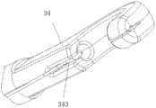
图3为图2中A部的局部放大图;Fig. 3 is a partial enlarged view of part A in Fig. 2;
图4为本发明实施例1提供的分体式手术缝合器中分体部分的剖面图;图 5为本发明实施例1提供的分体式手术缝合器中缝合端头部分的结构示意图;Fig. 4 is a sectional view of the split part in the split type surgical stapler provided by
图6为本发明实施例1提供的分体式手术缝合器中缝合线固定部分的结构 示意图;Fig. 6 is the structural representation of the suture fixing part in the split type surgical stapler provided in the embodiment of the
图7为本发明实施例1提供的分体式手术缝合器中线盘组件的结构示意图;7 is a schematic structural diagram of a split-type surgical stapler midline disk assembly provided in
图8为本发明实施例1提供的分体式手术缝合器的爆炸结构示意图;8 is a schematic diagram of an exploded structure of the split surgical stapler provided in
图9为本发明实施例2提供的分体式手术缝合器的整体结构示意图;9 is a schematic diagram of the overall structure of the split surgical stapler provided in
图10为本发明实施例2提供的分体式手术缝合器的整体剖面图;10 is an overall cross-sectional view of the split surgical stapler provided in
图11为本发明实施例2提供的分体式手术缝合器中缝合端头部分的结构示 意图;Fig. 11 is the structural representation of the suture tip part in the split-type surgical stapler provided in the embodiment of the
图12为本发明实施例2提供的分体式手术缝合器中缝合端头组件的结构示 意图。Figure 12 is a schematic structural diagram of the suture tip assembly in the split-type surgical stapler provided in
具体实施方式Detailed ways
为了使本发明的目的、技术方案及优点更加清楚明白,以下结合附图及实 施例,对本发明进行进一步详细说明。应当理解,此处所描述的具体实施例仅 仅用以解释本发明,并不用于限定本发明。In order to make the objects, technical solutions and advantages of the present invention more clearly understood, the present invention will be further described in detail below with reference to the accompanying drawings and embodiments. It should be understood that the specific embodiments described herein are only used to explain the present invention, but not to limit the present invention.
实施例1Example 1
本发明实施例1提供的一种分体式手术缝合器,如图1所示,包括主体控 制部分1、分体部分2、缝合端头部分3以及缝合线固定部分4,分体部分2的 一端与主体控制部分1活动连接,另一端与缝合端头部分3连接,缝合线固定 部分4设置在分体部分2的外部且与分体部分2连接;该结构通过在主体控制 部分1与缝合端头部分3之间设置可拆装的分体部分,这样,当手术完成后, 医术人员仅需更换分体部分2即可进行再次缝合手术的作用,从而实现了对主 体控制部分1的重复利用,有效的降低了制作缝合器的成本;同时,缝合线固定部分设置在分体部分2的外部且与分体部分2连接,有利于缝合线的固定和 使用时的导引。A split type surgical stapler provided in
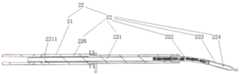
进一步地,如图2、图3、图4所示,分体部分2包括中空结构的分体件主 体21、从动杆组件22,从动杆组件22设置在分体件主体21内,分体件主体 21的一端与主体控制部分1活动连接,另一端与缝合端头部分3连接。Further, as shown in FIG. 2 , FIG. 3 , and FIG. 4 , the
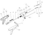
进一步地,如图3所示,所述主体控制部分1包括扳机11、具有握持手柄 的外壳组件12、设置在外壳组件12外的尾端旋转组件13以及设置在壳组件12 内的主动杆14,尾端旋转组件13与主动杆14的一端配合连接用于固定或松开 主动杆14,所述扳机11与主动杆14固接用于推动主动杆14向前位移;主动 杆14与从动杆组件22配合连接。Further, as shown in FIG. 3 , the main
进一步地,主体控制部分1还包括分体固定组件15,分体固定组件15的 一侧设置在主体控制部分1中外壳组件12靠近分体件主体21一端的内部,所 述分体件主体21通过分体固定组件15与外壳组件12活动连接。Further, the main
进一步地,分体固定组件15包括分件固定件主体151、分件活动件主体152、 第一弹性件153,第一弹性件153、分件活动件主体153从里至外依次套设在分 件固定件主体151上,且所述第一弹性件153的一端与分件固定件主体151固 定连接。Further, the split
进一步地,分件固定件主体151的内壁上设置有凸起1511,所述分体件主 体21的外壁上设置有卡槽211,凸起1511与卡槽211配合连接。Further, a
进一步地,从动杆组件22包括第一从动杆221、第一弯曲件222、第一连 接杆223、缝合针头224,从动杆221、连接杆223分别设置在弯曲件222的两 端且与第一弯曲件232固接,缝合针头224与第一连接杆223远离第一弯曲件 222的一端连接,主体控制部分1中的主动杆14与第一从动杆221远离第一弯 曲件222的一端配合连接。Further, the driven
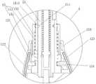
进一步地,如图5所示,缝合端头部分3包括中空结构的第一缝合端头本 体31、线头固定件32,第一缝合端头本体31的一端呈弯曲状,第一缝合端头 本体31的一端设置有可使所述缝合针头234置入固定、用于缝合损伤组织的第 一通槽311,第一通槽311的侧壁上设置有用于固定固定件32的通孔;第一缝 合端头本体31弯曲的一端与分体件主体21固定连接。Further, as shown in FIG. 5 , the
进一步地,第一缝合端头本体31底部设置有用于定位缝合线的缝隙343。Further, the bottom of the first
进一步地,如图2、图4、图5所示,第一缝合端头本体31相对所述分体 件主体21长度方向的弯曲角度为10~20度。Further, as shown in Fig. 2, Fig. 4, and Fig. 5, the bending angle of the first
进一步地,如图6、图7所示,缝合线固定部分4包括线盘组件41、线盘 定位筒42、固定扣件43以及连接件44,线盘定位筒42套设在分体件主体21 上,固定扣件43固设在线盘定位筒42上,线盘组件41穿设在固定扣件43上 且通过连接件44与固定扣件43连接。Further, as shown in FIGS. 6 and 7 , the
进一步地,线盘组件41包括上盘体411、下盘体412,上盘体411与下盘 体412固接,连接件44设置在上盘体411内,上盘体411通过连接件44与固 定扣件43连接;下盘体412上设置有一开设有线头嵌入槽417且用于缠绕缝合 线的凸台415。Further, the
进一步地,如图2、图/3所示,主体控制部分1还包括设置在壳组件12内 的第三弹性组件16,第三弹性组件16套设在主动杆14上用于主动杆14的回 位,从动杆组件22还包括第二弹性件229,第二弹性件229套设在第一从动杆 221用于第一从动杆221的回位。Further, as shown in FIGS. 2 and 3 , the main
进一步地,如图4所示,第一从动杆221远离第一弯曲件222的一端侧壁 上设置有用于供第二弹性件229产生弹力的限位件2211。Further, as shown in FIG. 4 , a limiting
进一步地,如图2、图10所示,尾端旋转组件13包括尾端旋转件131、旋 转固定件132,尾端旋转件131套设在旋转固定件132上,述主动杆14的一端 与旋转固定件132配合连接。Further, as shown in FIGS. 2 and 10 , the tail
进一步地,第三弹性组件16为一弹簧,外壳组件12内设置有供弹簧产生 弹性的限位凸起125,弹簧与限位凸起125相抵接。Further, the third
进一步地,弹簧与限位凸起125之间还设置有弹簧垫片16,通过设置弹簧 垫片16有效的保护了左、右壳体不被弹簧破坏。Further, a
进一步地,如图2、图3所示,外壳组件12包括主体左壳122、主体右壳 123、左右壳固定件124,左壳体122与右壳体123通过左右壳体固定件124配 合连接;通过设置外壳组件12,有效的固定和限制了主体控制部分1的部分部 件。Further, as shown in FIGS. 2 and 3 , the
本发明实施例1提供的一种分体式手术缝合器的使用过程如下:The use process of a split-type surgical stapler provided in
1)将尾端旋转件131顺时针旋转,使主动杆14固定解除;1) Rotate the rear
2)通过手指指引,将缝合端头3置入所需缝合韧带组织部位,利用第一通 槽311将韧带组织固定于通槽内;2) by finger guidance, the
3)将扳机11往手心方向用力握紧,此时主动杆14推动动杆组件22再将 带线头塑胶件33穿过韧带组织,成功送入固定件32通槽内并同固定件32一起 固定于第一缝合端头本体31卡槽内卡紧;3) Firmly hold the
4)松开扳机11,主动杆14连同动杆组件23部分一起缩回,带线头塑胶 件33停留在前端卡槽内;4) release the
5)移动缝合位置,再将扳机11往手心方向用力握紧,主动推杆14及从动 杆22再次穿过韧带组织达到固定件32通槽内;5) move the suture position, then the
6通过手指按压固定件32前端端头,同时连同扳机11一起缓慢松开,缝 合针头234将带线头塑胶件33带回于初始位置,此时单次缝合动作完成,连续 缝合即重复上述操作即可;6 Press the front end of the fixing
7缝合动作全部完成后,将缝合器取出,将分体部分2拆卸,完成全部缝 合动作。7 After the stitching action is completed, take out the stitcher, disassemble the
实施例2Example 2
本发明实施例2提供的一种分体式手术缝合器,如图9所示,包括主体控 制部分1、分体部分2、缝合端头部分3以及缝合线固定部分4,分体部分2的 一端与主体控制部分1活动连接,另一端与缝合端头部分3连接,缝合线固定 部分4设置在分体部分2的外部且与分体部分2连接;该结构通过在主体控制 部分1与缝合端头部分3之间设置可拆装的分体部分,这样,当手术完成后, 医术人员仅需更换分体部分2即可进行再次缝合手术的作用,从而实现了对主 体控制部分1的重复利用,有效的降低了制作缝合器的成本;同时,缝合线固定部分设置在分体部分2的外部且与分体部分2连接,有利于缝合线的固定和 使用时的导引。A split type surgical stapler provided in
进一步地,如图10所示,分体部分2包括中空结构的分体件主体21、从 动杆组件22,从动杆组件22设置在分体件主体21内,分体件主体21的一端 与主体控制部分1活动连接,另一端与缝合端头部分3连接。Further, as shown in FIG. 10 , the
进一步地,主体控制部分1包括扳机11、具有握持手柄的外壳组件12、设 置在外壳组件12外的尾端旋转组件13以及设置在壳组件12内的主动杆14, 尾端旋转组件13与主动杆14的一端配合连接用于固定或松开主动杆14,扳机 11与主动杆14固接用于推动主动杆14向前位移;所述主动杆14与从动杆组 件22配合连接。Further, the main
进一步地,主体控制部分1还包括分体固定组件15,分体固定组件15的 一侧设置在主体控制部分1中外壳组件12靠近分体件主体21一端的内部,分 体件主体21通过分体固定组件15与外壳组件12活动连接。Further, the main
进一步地,分体固定组件15包括分件固定件主体151、分件活动件主体152、 第一弹性件153,第一弹性件153、分件活动件主体153从里至外依次套设在分 件固定件主体151上,且所述第一弹性件153的一端与分件固定件主体151固 定连接。Further, the
进一步地,分件固定件主体151的内壁上设置有凸起1511,所述分体件主 体21的外壁上设置有卡槽211,所述凸起1511与卡槽211配合连接。Further, a
进一步地,从动杆组件22包括第二从动杆225、第二弯曲件226、第二连 接杆227、缝合针头组件228,所述第二从动杆225、第二连接杆226分别设置 在第二弯曲件226的两端且与第二弯曲件226固接,缝合针头组件228与第二 连接杆227远离第二弯曲件226的一端连接,主体控制部分1与第二从动杆225 远离第二弯曲件226的一端配合连接。Further, the driven
进一步地,缝合针组件228包括推杆针2281、推杆帽2282,所述推杆帽 2282套设在推杆针2281端部,所述推杆针2281的底部与第二连接杆227连接。Further, the
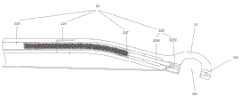
进一步地,缝合端头部分3包括中空结构的第二缝合端头本体34,第二缝 合端头本体34的一端呈弯曲状,第二缝合端头本体34的一端设置有可使所述 推杆针2281置入固定、用于缝合损伤组织的第二通槽341,第二通槽341的槽 壁上设置有用于固定推杆帽2282的固定槽342,第二缝合端头本体34弯曲的 一端与分体件主体21固定连接。Further, the
进一步地,如图12所示,第二缝合端头本体34的底部设置有用于定位缝 合线的缝隙343。Further, as shown in FIG. 12 , the bottom of the second
进一步地,如图10、图11所示,第二缝合端头本体34相对所述分体件主 体21长度方向的弯曲角度为10~20度。Further, as shown in Fig. 10 and Fig. 11 , the bending angle of the second
进一步地,如图6、图7所示,缝合线固定部分4包括线盘组件41、线盘 定位筒42、固定扣件43以及连接件44,线盘定位筒42套设在分体件主体21 上,固定扣件43固设在线盘定位筒42上,线盘组件41穿设在固定扣件43上 且通过连接件44与固定扣件43连接。Further, as shown in FIGS. 6 and 7 , the
进一步地,线盘组件41包括上盘体411、下盘体412,上盘体411与下盘 体412固接,连接件44设置在上盘体411内,上盘体411通过连接件44与固 定扣件43连接;下盘体412上设置有一开设有线头嵌入槽417且用于缠绕缝合 线的凸台415。Further, the
进一步地,如图10、图11所示,主体控制部分1还包括设置在壳组件12 内的第三弹性组件16,第三弹性组件16套设在主动杆14上用于主动杆14的 回位,从动杆组件22还包括第二弹性件229,第二弹性件229套设在第二从动 杆225上用于第二从动杆225的回位。Further, as shown in FIG. 10 and FIG. 11 , the main
进一步地,如图10所示,第二从动杆225远离第二弯曲件226的一端侧壁 上设置有用于供第二弹性件229产生弹力的限位件2211。Further, as shown in Fig. 10 , a limiting
进一步地,尾端旋转组件13包括尾端旋转件131、旋转固定件132,所述 尾端旋转件131套设在旋转固定件132上,主动杆14的一端与旋转固定件132 配合连接。Further, the tail
进一步地,第三弹性组件16为一弹簧,外壳组件12内设置有供弹簧产生 弹性的限位凸起125,弹簧与限位凸起125相抵接。Further, the third
进一步地,弹簧与限位凸起125之间还设置有弹簧垫片17,通过设置弹簧 垫片17有效的保护了左、右壳体不被弹簧破坏。Further, a
进一步地,如图3所示,外壳组件12包括主体左壳122、主体右壳123、 左右壳固定件124,左壳体122与右壳体123通过左右壳体固定件124配合连 接;通过设置外壳组件12,有效的固定和限制了主体控制部分1的部分部件。Further, as shown in FIG. 3 , the
本发明实施例2提供的一种分体式手术缝合器的使用过程如下:The use process of a split-type surgical stapler provided in
1)将尾端旋转件131顺时针旋转,使主动杆14固定解除;1) Rotate the rear
2)通过手指指引,将缝合端头3置入所需缝合韧带组织部位,利用341 将韧带组织固定于通槽内;2) Under the guidance of fingers, place the
3)将扳机11往手心方向用力握紧,此时主动杆14推动动杆组件22再将 固定推杆帽2382穿过韧带组织,成功送入固定槽342通槽内并卡紧;3) the
4)松开扳机11,主动杆14连同动杆组件22部分一起缩回,固定推杆帽 2382停留在固定槽342卡槽内,此时一次缝合完毕;4) Release the
5)将缝合器取出,将缝合线固定部分4拆卸下来,更换新的缝合线固定部 分4部件继续完成缝合动作;5) take out the suture, disassemble the
6)将缝合器取出,再将分体部分2拆卸下来,完成缝合手术全部动作。6) Take out the suturing device, and then disassemble the
本发明器械,专用于手术中身体腔隙深部、狭小空间的组织缝合;本发明 通过在主体控制部分1与缝合端头部分3之间设置可拆装的分体部分2,这样, 当手术完成后,医术人员仅需更换分体部分即可进行再次缝合手术的作用,从 而实现了对主体控制部分1的重复利用,有效的降低了制作缝合器的成本;另 外,该结构操作简单方便,手术中仅需分离出较小的空间,用手指探及深部韧 带组织,在手指指引下即可完成缝合,勿需直视,一次缝合成功率高,且可反 复缝合,大大缩短手术时间,缝合精准,不易误伤邻近器官,减小了手术副损 伤。The instrument of the present invention is specially used for tissue suturing in the deep part of the body cavity and the narrow space during the operation; the present invention provides a
以上所述,仅为本发明较佳的具体实施方式,但本发明的保护范围并不局 限于此,任何熟悉本技术领域的技术人员在本发明揭露的技术范围内,可轻易 想到的变化或替换,都应涵盖在本发明的保护范围之内。因此,本发明的保护 范围应该以权利要求的保护范围为准。The above description is only a preferred embodiment of the present invention, but the protection scope of the present invention is not limited to this. Substitutions should be covered within the protection scope of the present invention. Therefore, the protection scope of the present invention should be subject to the protection scope of the claims.
Claims (18)
Priority Applications (2)
| Application Number | Priority Date | Filing Date | Title |
|---|---|---|---|
| CN201910461517.3ACN112089458A (en) | 2019-05-30 | 2019-05-30 | Split surgical stapler |
| PCT/CN2019/104427WO2020237893A1 (en) | 2019-05-30 | 2019-09-04 | Split type surgical suture device |
Applications Claiming Priority (1)
| Application Number | Priority Date | Filing Date | Title |
|---|---|---|---|
| CN201910461517.3ACN112089458A (en) | 2019-05-30 | 2019-05-30 | Split surgical stapler |
Publications (1)
| Publication Number | Publication Date |
|---|---|
| CN112089458Atrue CN112089458A (en) | 2020-12-18 |
Family
ID=73551971
Family Applications (1)
| Application Number | Title | Priority Date | Filing Date |
|---|---|---|---|
| CN201910461517.3APendingCN112089458A (en) | 2019-05-30 | 2019-05-30 | Split surgical stapler |
Country Status (2)
| Country | Link |
|---|---|
| CN (1) | CN112089458A (en) |
| WO (1) | WO2020237893A1 (en) |
Cited By (1)
| Publication number | Priority date | Publication date | Assignee | Title |
|---|---|---|---|---|
| WO2023201461A1 (en)* | 2022-04-18 | 2023-10-26 | 迈磊医疗器材股份有限公司 | Automatic suturing instrument |
Citations (5)
| Publication number | Priority date | Publication date | Assignee | Title |
|---|---|---|---|---|
| CN2805693Y (en)* | 2005-07-12 | 2006-08-16 | 田海 | Deep tissue stitching device |
| US20060282099A1 (en)* | 2005-06-13 | 2006-12-14 | Stokes Michael J | Method for suture lacing |
| US20080177134A1 (en)* | 2005-01-14 | 2008-07-24 | Manabu Miyamoto | Surgical treatment instrument |
| CN101902975A (en)* | 2007-10-18 | 2010-12-01 | 尼奥绰德有限公司 | Minimally invasive repair of valve leaflets in beating heart |
| CN211534588U (en)* | 2019-05-30 | 2020-09-22 | 香港大学深圳医院 | Split type operation stitching instrument |
Family Cites Families (7)
| Publication number | Priority date | Publication date | Assignee | Title |
|---|---|---|---|---|
| US5908428A (en)* | 1997-05-27 | 1999-06-01 | United States Surgical Corporation | Stitching devices for heart valve replacement surgery |
| US6280460B1 (en)* | 1998-02-13 | 2001-08-28 | Heartport, Inc. | Devices and methods for performing vascular anastomosis |
| US9775600B2 (en)* | 2010-10-01 | 2017-10-03 | Endoevolution, Llc | Devices and methods for minimally invasive suturing |
| CA2666698C (en)* | 2006-08-16 | 2015-02-03 | Wilson-Cook Medical, Inc. | Suturing device |
| ATE543441T1 (en)* | 2006-11-07 | 2012-02-15 | Boston Scient Ltd | SUT RELEASE |
| EP2986233B1 (en)* | 2013-04-16 | 2022-06-15 | Teleflex Medical Incorporated | Needlescopic instrument with reusable handle and detachable needle assembly |
| CN108969045B (en)* | 2014-03-26 | 2021-02-26 | 柯惠有限合伙公司 | Surgical stapling device |
- 2019
- 2019-05-30CNCN201910461517.3Apatent/CN112089458A/enactivePending
- 2019-09-04WOPCT/CN2019/104427patent/WO2020237893A1/ennot_activeCeased
Patent Citations (5)
| Publication number | Priority date | Publication date | Assignee | Title |
|---|---|---|---|---|
| US20080177134A1 (en)* | 2005-01-14 | 2008-07-24 | Manabu Miyamoto | Surgical treatment instrument |
| US20060282099A1 (en)* | 2005-06-13 | 2006-12-14 | Stokes Michael J | Method for suture lacing |
| CN2805693Y (en)* | 2005-07-12 | 2006-08-16 | 田海 | Deep tissue stitching device |
| CN101902975A (en)* | 2007-10-18 | 2010-12-01 | 尼奥绰德有限公司 | Minimally invasive repair of valve leaflets in beating heart |
| CN211534588U (en)* | 2019-05-30 | 2020-09-22 | 香港大学深圳医院 | Split type operation stitching instrument |
Cited By (1)
| Publication number | Priority date | Publication date | Assignee | Title |
|---|---|---|---|---|
| WO2023201461A1 (en)* | 2022-04-18 | 2023-10-26 | 迈磊医疗器材股份有限公司 | Automatic suturing instrument |
Also Published As
| Publication number | Publication date |
|---|---|
| WO2020237893A1 (en) | 2020-12-03 |
Similar Documents
| Publication | Publication Date | Title |
|---|---|---|
| US8398657B2 (en) | Multi-fire suturing instrument with proximal ferrule release feature | |
| RU2623130C2 (en) | Linear suturing device | |
| US6099537A (en) | Medical treatment instrument | |
| RU2011106943A (en) | DEVICE FOR APPLICATION OF CLIPPING ELEMENTS WITH DISPOSABLE CARTRIDGE USED IN RESTRICTIVE GASTROPLASTIC | |
| CN103153204B (en) | Methods and devices for guiding sutures | |
| WO2018173474A1 (en) | Surgical clipping tool | |
| JP2019010511A (en) | Suture magazine for suture passing surgical device | |
| JP5046951B2 (en) | Gripping tool | |
| CN112089458A (en) | Split surgical stapler | |
| JP6294016B2 (en) | Endoscope clip | |
| CN211534588U (en) | Split type operation stitching instrument | |
| CN112089457B (en) | Integrated surgical stapler | |
| CN112869832B (en) | A circumcision stapler | |
| CN211155982U (en) | An integrated surgical stapler | |
| JP2007275386A (en) | Medical forceps | |
| CN110251187B (en) | Mechanical separable hemostatic forceps device | |
| JP6300274B2 (en) | Endoscope lens wiping device and endoscope provided with the wiping device | |
| JP2017012532A (en) | Clip unit for ligation device and cartridge for clip unit | |
| JP5687891B2 (en) | Auxiliary device for gastric wall fixation device | |
| JP2010125202A (en) | Surgical device for prosthetic joint | |
| JP5224279B2 (en) | Endoscopic magnetic anchor guidance device | |
| JP6049583B2 (en) | Laryngoscope and medical system using the same | |
| JP5787601B2 (en) | Puncture device | |
| JP6592778B2 (en) | Finger mounted surgical tool | |
| CN115279245A (en) | Lift assembly and endoscope |
Legal Events
| Date | Code | Title | Description |
|---|---|---|---|
| PB01 | Publication | ||
| PB01 | Publication | ||
| SE01 | Entry into force of request for substantive examination | ||
| SE01 | Entry into force of request for substantive examination |