CN112088022A - System and method for estimating the position of a cardiac pump - Google Patents
System and method for estimating the position of a cardiac pumpDownload PDFInfo
- Publication number
- CN112088022A CN112088022ACN201980032393.5ACN201980032393ACN112088022ACN 112088022 ACN112088022 ACN 112088022ACN 201980032393 ACN201980032393 ACN 201980032393ACN 112088022 ACN112088022 ACN 112088022A
- Authority
- CN
- China
- Prior art keywords
- differential pressure
- time
- data
- varying
- pump system
- Prior art date
- Legal status (The legal status is an assumption and is not a legal conclusion. Google has not performed a legal analysis and makes no representation as to the accuracy of the status listed.)
- Granted
Links
Images


Classifications
- A—HUMAN NECESSITIES
- A61—MEDICAL OR VETERINARY SCIENCE; HYGIENE
- A61M—DEVICES FOR INTRODUCING MEDIA INTO, OR ONTO, THE BODY; DEVICES FOR TRANSDUCING BODY MEDIA OR FOR TAKING MEDIA FROM THE BODY; DEVICES FOR PRODUCING OR ENDING SLEEP OR STUPOR
- A61M60/00—Blood pumps; Devices for mechanical circulatory actuation; Balloon pumps for circulatory assistance
- A61M60/50—Details relating to control
- A—HUMAN NECESSITIES
- A61—MEDICAL OR VETERINARY SCIENCE; HYGIENE
- A61B—DIAGNOSIS; SURGERY; IDENTIFICATION
- A61B5/00—Measuring for diagnostic purposes; Identification of persons
- A61B5/72—Signal processing specially adapted for physiological signals or for diagnostic purposes
- A61B5/7235—Details of waveform analysis
- A61B5/7239—Details of waveform analysis using differentiation including higher order derivatives
- A—HUMAN NECESSITIES
- A61—MEDICAL OR VETERINARY SCIENCE; HYGIENE
- A61M—DEVICES FOR INTRODUCING MEDIA INTO, OR ONTO, THE BODY; DEVICES FOR TRANSDUCING BODY MEDIA OR FOR TAKING MEDIA FROM THE BODY; DEVICES FOR PRODUCING OR ENDING SLEEP OR STUPOR
- A61M60/00—Blood pumps; Devices for mechanical circulatory actuation; Balloon pumps for circulatory assistance
- A61M60/10—Location thereof with respect to the patient's body
- A61M60/122—Implantable pumps or pumping devices, i.e. the blood being pumped inside the patient's body
- A—HUMAN NECESSITIES
- A61—MEDICAL OR VETERINARY SCIENCE; HYGIENE
- A61B—DIAGNOSIS; SURGERY; IDENTIFICATION
- A61B5/00—Measuring for diagnostic purposes; Identification of persons
- A61B5/0002—Remote monitoring of patients using telemetry, e.g. transmission of vital signals via a communication network
- A61B5/0031—Implanted circuitry
- A—HUMAN NECESSITIES
- A61—MEDICAL OR VETERINARY SCIENCE; HYGIENE
- A61B—DIAGNOSIS; SURGERY; IDENTIFICATION
- A61B5/00—Measuring for diagnostic purposes; Identification of persons
- A61B5/02—Detecting, measuring or recording for evaluating the cardiovascular system, e.g. pulse, heart rate, blood pressure or blood flow
- A61B5/024—Measuring pulse rate or heart rate
- A—HUMAN NECESSITIES
- A61—MEDICAL OR VETERINARY SCIENCE; HYGIENE
- A61M—DEVICES FOR INTRODUCING MEDIA INTO, OR ONTO, THE BODY; DEVICES FOR TRANSDUCING BODY MEDIA OR FOR TAKING MEDIA FROM THE BODY; DEVICES FOR PRODUCING OR ENDING SLEEP OR STUPOR
- A61M60/00—Blood pumps; Devices for mechanical circulatory actuation; Balloon pumps for circulatory assistance
- A61M60/10—Location thereof with respect to the patient's body
- A61M60/122—Implantable pumps or pumping devices, i.e. the blood being pumped inside the patient's body
- A61M60/126—Implantable pumps or pumping devices, i.e. the blood being pumped inside the patient's body implantable via, into, inside, in line, branching on, or around a blood vessel
- A61M60/13—Implantable pumps or pumping devices, i.e. the blood being pumped inside the patient's body implantable via, into, inside, in line, branching on, or around a blood vessel by means of a catheter allowing explantation, e.g. catheter pumps temporarily introduced via the vascular system
- A—HUMAN NECESSITIES
- A61—MEDICAL OR VETERINARY SCIENCE; HYGIENE
- A61M—DEVICES FOR INTRODUCING MEDIA INTO, OR ONTO, THE BODY; DEVICES FOR TRANSDUCING BODY MEDIA OR FOR TAKING MEDIA FROM THE BODY; DEVICES FOR PRODUCING OR ENDING SLEEP OR STUPOR
- A61M60/00—Blood pumps; Devices for mechanical circulatory actuation; Balloon pumps for circulatory assistance
- A61M60/10—Location thereof with respect to the patient's body
- A61M60/122—Implantable pumps or pumping devices, i.e. the blood being pumped inside the patient's body
- A61M60/126—Implantable pumps or pumping devices, i.e. the blood being pumped inside the patient's body implantable via, into, inside, in line, branching on, or around a blood vessel
- A61M60/135—Implantable pumps or pumping devices, i.e. the blood being pumped inside the patient's body implantable via, into, inside, in line, branching on, or around a blood vessel inside a blood vessel, e.g. using grafting
- A—HUMAN NECESSITIES
- A61—MEDICAL OR VETERINARY SCIENCE; HYGIENE
- A61M—DEVICES FOR INTRODUCING MEDIA INTO, OR ONTO, THE BODY; DEVICES FOR TRANSDUCING BODY MEDIA OR FOR TAKING MEDIA FROM THE BODY; DEVICES FOR PRODUCING OR ENDING SLEEP OR STUPOR
- A61M60/00—Blood pumps; Devices for mechanical circulatory actuation; Balloon pumps for circulatory assistance
- A61M60/10—Location thereof with respect to the patient's body
- A61M60/122—Implantable pumps or pumping devices, i.e. the blood being pumped inside the patient's body
- A61M60/126—Implantable pumps or pumping devices, i.e. the blood being pumped inside the patient's body implantable via, into, inside, in line, branching on, or around a blood vessel
- A61M60/148—Implantable pumps or pumping devices, i.e. the blood being pumped inside the patient's body implantable via, into, inside, in line, branching on, or around a blood vessel in line with a blood vessel using resection or like techniques, e.g. permanent endovascular heart assist devices
- A—HUMAN NECESSITIES
- A61—MEDICAL OR VETERINARY SCIENCE; HYGIENE
- A61M—DEVICES FOR INTRODUCING MEDIA INTO, OR ONTO, THE BODY; DEVICES FOR TRANSDUCING BODY MEDIA OR FOR TAKING MEDIA FROM THE BODY; DEVICES FOR PRODUCING OR ENDING SLEEP OR STUPOR
- A61M60/00—Blood pumps; Devices for mechanical circulatory actuation; Balloon pumps for circulatory assistance
- A61M60/10—Location thereof with respect to the patient's body
- A61M60/122—Implantable pumps or pumping devices, i.e. the blood being pumped inside the patient's body
- A61M60/165—Implantable pumps or pumping devices, i.e. the blood being pumped inside the patient's body implantable in, on, or around the heart
- A61M60/17—Implantable pumps or pumping devices, i.e. the blood being pumped inside the patient's body implantable in, on, or around the heart inside a ventricle, e.g. intraventricular balloon pumps
- A61M60/174—Implantable pumps or pumping devices, i.e. the blood being pumped inside the patient's body implantable in, on, or around the heart inside a ventricle, e.g. intraventricular balloon pumps discharging the blood to the ventricle or arterial system via a cannula internal to the ventricle or arterial system
- A—HUMAN NECESSITIES
- A61—MEDICAL OR VETERINARY SCIENCE; HYGIENE
- A61M—DEVICES FOR INTRODUCING MEDIA INTO, OR ONTO, THE BODY; DEVICES FOR TRANSDUCING BODY MEDIA OR FOR TAKING MEDIA FROM THE BODY; DEVICES FOR PRODUCING OR ENDING SLEEP OR STUPOR
- A61M60/00—Blood pumps; Devices for mechanical circulatory actuation; Balloon pumps for circulatory assistance
- A61M60/20—Type thereof
- A61M60/205—Non-positive displacement blood pumps
- A61M60/216—Non-positive displacement blood pumps including a rotating member acting on the blood, e.g. impeller
- A—HUMAN NECESSITIES
- A61—MEDICAL OR VETERINARY SCIENCE; HYGIENE
- A61M—DEVICES FOR INTRODUCING MEDIA INTO, OR ONTO, THE BODY; DEVICES FOR TRANSDUCING BODY MEDIA OR FOR TAKING MEDIA FROM THE BODY; DEVICES FOR PRODUCING OR ENDING SLEEP OR STUPOR
- A61M60/00—Blood pumps; Devices for mechanical circulatory actuation; Balloon pumps for circulatory assistance
- A61M60/40—Details relating to driving
- A61M60/403—Details relating to driving for non-positive displacement blood pumps
- A61M60/408—Details relating to driving for non-positive displacement blood pumps the force acting on the blood contacting member being mechanical, e.g. transmitted by a shaft or cable
- A61M60/411—Details relating to driving for non-positive displacement blood pumps the force acting on the blood contacting member being mechanical, e.g. transmitted by a shaft or cable generated by an electromotor
- A—HUMAN NECESSITIES
- A61—MEDICAL OR VETERINARY SCIENCE; HYGIENE
- A61M—DEVICES FOR INTRODUCING MEDIA INTO, OR ONTO, THE BODY; DEVICES FOR TRANSDUCING BODY MEDIA OR FOR TAKING MEDIA FROM THE BODY; DEVICES FOR PRODUCING OR ENDING SLEEP OR STUPOR
- A61M60/00—Blood pumps; Devices for mechanical circulatory actuation; Balloon pumps for circulatory assistance
- A61M60/50—Details relating to control
- A61M60/508—Electronic control means, e.g. for feedback regulation
- A61M60/538—Regulation using real-time blood pump operational parameter data, e.g. motor current
- A61M60/554—Regulation using real-time blood pump operational parameter data, e.g. motor current of blood pressure
- A—HUMAN NECESSITIES
- A61—MEDICAL OR VETERINARY SCIENCE; HYGIENE
- A61M—DEVICES FOR INTRODUCING MEDIA INTO, OR ONTO, THE BODY; DEVICES FOR TRANSDUCING BODY MEDIA OR FOR TAKING MEDIA FROM THE BODY; DEVICES FOR PRODUCING OR ENDING SLEEP OR STUPOR
- A61M60/00—Blood pumps; Devices for mechanical circulatory actuation; Balloon pumps for circulatory assistance
- A61M60/80—Constructional details other than related to driving
- A61M60/802—Constructional details other than related to driving of non-positive displacement blood pumps
- A61M60/81—Pump housings
- A61M60/816—Sensors arranged on or in the housing, e.g. ultrasound flow sensors
- A—HUMAN NECESSITIES
- A61—MEDICAL OR VETERINARY SCIENCE; HYGIENE
- A61M—DEVICES FOR INTRODUCING MEDIA INTO, OR ONTO, THE BODY; DEVICES FOR TRANSDUCING BODY MEDIA OR FOR TAKING MEDIA FROM THE BODY; DEVICES FOR PRODUCING OR ENDING SLEEP OR STUPOR
- A61M60/00—Blood pumps; Devices for mechanical circulatory actuation; Balloon pumps for circulatory assistance
- A61M60/80—Constructional details other than related to driving
- A61M60/802—Constructional details other than related to driving of non-positive displacement blood pumps
- A61M60/827—Sealings between moving parts
- A61M60/829—Sealings between moving parts having a purge fluid supply
- A—HUMAN NECESSITIES
- A61—MEDICAL OR VETERINARY SCIENCE; HYGIENE
- A61M—DEVICES FOR INTRODUCING MEDIA INTO, OR ONTO, THE BODY; DEVICES FOR TRANSDUCING BODY MEDIA OR FOR TAKING MEDIA FROM THE BODY; DEVICES FOR PRODUCING OR ENDING SLEEP OR STUPOR
- A61M60/00—Blood pumps; Devices for mechanical circulatory actuation; Balloon pumps for circulatory assistance
- A61M60/80—Constructional details other than related to driving
- A61M60/855—Constructional details other than related to driving of implantable pumps or pumping devices
- A61M60/865—Devices for guiding or inserting pumps or pumping devices into the patient's body
- A61M60/867—Devices for guiding or inserting pumps or pumping devices into the patient's body using position detection during deployment, e.g. for blood pumps mounted on and driven through a catheter
- A—HUMAN NECESSITIES
- A61—MEDICAL OR VETERINARY SCIENCE; HYGIENE
- A61M—DEVICES FOR INTRODUCING MEDIA INTO, OR ONTO, THE BODY; DEVICES FOR TRANSDUCING BODY MEDIA OR FOR TAKING MEDIA FROM THE BODY; DEVICES FOR PRODUCING OR ENDING SLEEP OR STUPOR
- A61M2205/00—General characteristics of the apparatus
- A61M2205/18—General characteristics of the apparatus with alarm
- A—HUMAN NECESSITIES
- A61—MEDICAL OR VETERINARY SCIENCE; HYGIENE
- A61M—DEVICES FOR INTRODUCING MEDIA INTO, OR ONTO, THE BODY; DEVICES FOR TRANSDUCING BODY MEDIA OR FOR TAKING MEDIA FROM THE BODY; DEVICES FOR PRODUCING OR ENDING SLEEP OR STUPOR
- A61M2205/00—General characteristics of the apparatus
- A61M2205/33—Controlling, regulating or measuring
- A61M2205/3331—Pressure; Flow
- A61M2205/3334—Measuring or controlling the flow rate
- A—HUMAN NECESSITIES
- A61—MEDICAL OR VETERINARY SCIENCE; HYGIENE
- A61M—DEVICES FOR INTRODUCING MEDIA INTO, OR ONTO, THE BODY; DEVICES FOR TRANSDUCING BODY MEDIA OR FOR TAKING MEDIA FROM THE BODY; DEVICES FOR PRODUCING OR ENDING SLEEP OR STUPOR
- A61M2205/00—General characteristics of the apparatus
- A61M2205/33—Controlling, regulating or measuring
- A61M2205/3331—Pressure; Flow
- A61M2205/3344—Measuring or controlling pressure at the body treatment site
- A—HUMAN NECESSITIES
- A61—MEDICAL OR VETERINARY SCIENCE; HYGIENE
- A61M—DEVICES FOR INTRODUCING MEDIA INTO, OR ONTO, THE BODY; DEVICES FOR TRANSDUCING BODY MEDIA OR FOR TAKING MEDIA FROM THE BODY; DEVICES FOR PRODUCING OR ENDING SLEEP OR STUPOR
- A61M2205/00—General characteristics of the apparatus
- A61M2205/33—Controlling, regulating or measuring
- A61M2205/3331—Pressure; Flow
- A61M2205/3351—Controlling upstream pump pressure
- A—HUMAN NECESSITIES
- A61—MEDICAL OR VETERINARY SCIENCE; HYGIENE
- A61M—DEVICES FOR INTRODUCING MEDIA INTO, OR ONTO, THE BODY; DEVICES FOR TRANSDUCING BODY MEDIA OR FOR TAKING MEDIA FROM THE BODY; DEVICES FOR PRODUCING OR ENDING SLEEP OR STUPOR
- A61M2205/00—General characteristics of the apparatus
- A61M2205/33—Controlling, regulating or measuring
- A61M2205/3331—Pressure; Flow
- A61M2205/3355—Controlling downstream pump pressure
- A—HUMAN NECESSITIES
- A61—MEDICAL OR VETERINARY SCIENCE; HYGIENE
- A61M—DEVICES FOR INTRODUCING MEDIA INTO, OR ONTO, THE BODY; DEVICES FOR TRANSDUCING BODY MEDIA OR FOR TAKING MEDIA FROM THE BODY; DEVICES FOR PRODUCING OR ENDING SLEEP OR STUPOR
- A61M2205/00—General characteristics of the apparatus
- A61M2205/33—Controlling, regulating or measuring
- A61M2205/3331—Pressure; Flow
- A61M2205/3358—Measuring barometric pressure, e.g. for compensation
- A—HUMAN NECESSITIES
- A61—MEDICAL OR VETERINARY SCIENCE; HYGIENE
- A61M—DEVICES FOR INTRODUCING MEDIA INTO, OR ONTO, THE BODY; DEVICES FOR TRANSDUCING BODY MEDIA OR FOR TAKING MEDIA FROM THE BODY; DEVICES FOR PRODUCING OR ENDING SLEEP OR STUPOR
- A61M2205/00—General characteristics of the apparatus
- A61M2205/70—General characteristics of the apparatus with testing or calibration facilities
- A61M2205/702—General characteristics of the apparatus with testing or calibration facilities automatically during use
Landscapes
- Health & Medical Sciences (AREA)
- Heart & Thoracic Surgery (AREA)
- Engineering & Computer Science (AREA)
- Life Sciences & Earth Sciences (AREA)
- Cardiology (AREA)
- Biomedical Technology (AREA)
- Animal Behavior & Ethology (AREA)
- General Health & Medical Sciences (AREA)
- Public Health (AREA)
- Veterinary Medicine (AREA)
- Anesthesiology (AREA)
- Hematology (AREA)
- Mechanical Engineering (AREA)
- Vascular Medicine (AREA)
- Biophysics (AREA)
- Pathology (AREA)
- Surgery (AREA)
- Molecular Biology (AREA)
- Medical Informatics (AREA)
- Physics & Mathematics (AREA)
- Physiology (AREA)
- Psychiatry (AREA)
- Signal Processing (AREA)
- Artificial Intelligence (AREA)
- Computer Vision & Pattern Recognition (AREA)
- Transplantation (AREA)
- Computer Networks & Wireless Communication (AREA)
- External Artificial Organs (AREA)
Abstract
Description
Translated fromChinese相关申请的引用Citations to Related Applications
本申请要求2018年3月16日提交的标题为“SYSTEMS AND METHODS FOR ESTIMATING APOSITION OF A HEART PUMP”的美国临时专利申请号62/644,240的优先权和权益,并与2019年3月15日提交的标题为“SYSTEMS AND METHODS FOR ESTIMATING A POSITION OF AHEART PUMP”的美国专利申请号16/354,595相关。上面提及的申请的全部内容通过引用并入本文。This application claims priority to and the benefit of U.S. Provisional Patent Application No. 62/644,240, filed March 16, 2018, entitled "SYSTEMS AND METHODS FOR ESTIMATING APOSITION OF A HEART PUMP," and is related to US Patent Application No. 16/354,595 entitled "SYSTEMS AND METHODS FOR ESTIMATING A POSITION OF AHEART PUMP" is related. The entire contents of the above-mentioned applications are incorporated herein by reference.
背景技术Background technique
急性和慢性心血管疾病会降低生活质量和预期寿命。从药物到机械设备和移植,人们已开发了多种用于心脏健康的治疗方式。临时心脏支持设备如心脏泵系统将提供血液动力学支持,并促进心脏康复。一些心脏泵系统经皮插入心脏中并可与天然心脏平行运行以补充心脏输出,如IMPELLA®系列设备(Abiomed, Inc., Danvers MA)。这样的心脏泵系统可测量和/或计算对确定患者健康状况和判断心脏泵系统的运行有用的心脏泵参数。Acute and chronic cardiovascular disease reduces quality of life and life expectancy. From drugs to mechanical devices and transplants, a variety of treatments have been developed for heart health. Temporary cardiac support equipment such as a heart pump system will provide hemodynamic support and facilitate cardiac rehabilitation. Some cardiac pumping systems are inserted percutaneously into the heart and run in parallel with the native heart to supplement cardiac output, such as the IMPELLA® series of devices (Abiomed, Inc., Danvers MA). Such a heart pump system may measure and/or calculate heart pump parameters useful for determining patient health and for determining the operation of the heart pump system.
这些测量值可通过传感器收集,但传感器易出故障。当心脏泵系统传感器发生故障时,临床医生将失去许多有价值的测量值,如流量估计、位置监测和抽吸警报。如果传感器发生故障,即使泵本身功能正常,临床医生也经常会从患者身上卸下心脏泵系统。不希望卸下和更换心脏泵系统,尤其是在泵功能正常的情况下,因为这样做会增加向患者引入细菌的风险。更换心脏泵系统可能很昂贵并且会导致心脏泵系统的“浪费”。此外,卸下和更换心脏泵系统可能会从患者的血泵支持和因此康复中夺走宝贵的时间。These measurements can be collected by sensors, but sensors are prone to failure. When cardiac pump system sensors fail, clinicians lose many valuable measurements, such as flow estimates, position monitoring, and aspiration alerts. If the sensor fails, clinicians often remove the heart pumping system from the patient, even if the pump itself is functioning properly. Removing and replacing the cardiac pump system is undesirable, especially if the pump is functioning properly, as doing so increases the risk of introducing bacteria to the patient. Replacing a heart pump system can be expensive and result in "waste" of the heart pump system. Additionally, removing and replacing the heart pump system can take away valuable time from the patient's blood pump support and thus recovery.
发明内容SUMMARY OF THE INVENTION
本文所述的系统、设备和方法提供了当位于患者心脏内时心脏泵的位置的估计。特别地,所述系统和方法对特定的心脏泵系统确定电机电流与压差信号之间的关系,并然后使用此关系来从后来接收的电机电流数据确定时变压差的估计值。从估计的压差,心脏泵系统估计泵流量、触发抽吸警报和触发定位警报。The systems, devices, and methods described herein provide an estimate of the position of the heart pump when located within the patient's heart. In particular, the systems and methods determine the relationship between the motor current and the differential pressure signal for a particular heart pump system, and then use this relationship to determine an estimate of the time-varying differential pressure from subsequently received motor current data. From the estimated differential pressure, the cardiac pump system estimates pump flow, triggers aspiration alarms, and triggers positioning alarms.
控制器可配置为执行本文描述的任何实施方式、方面和方法。例如,控制器可以是Abiomed, Inc的自动化Impella控制器(Automated Impella Controller, AIC)或任何其他合适的控制器。在一些实施方式中,心脏泵系统包括导管;电机;可操作地联接至电机的转子;泵壳体,其至少部分地围绕转子,使得伺服电机驱动转子并泵送血液通过泵壳体;一个或多个传感器,包括压差传感器;和控制器。例如,心脏泵系统可包括Abiomed, Inc的Impella RP心脏泵或Impella 5.0心脏泵,其连接至AIC或任何其他合适的系统。The controller may be configured to perform any of the embodiments, aspects and methods described herein. For example, the controller may be an Automated Impella Controller (AIC) from Abiomed, Inc or any other suitable controller. In some embodiments, a heart pump system includes a catheter; a motor; a rotor operably coupled to the motor; a pump housing at least partially surrounding the rotor such that the servomotor drives the rotor and pumps blood through the pump housing; one or a plurality of sensors, including a differential pressure sensor; and a controller. For example, a heart pump system may include an Impella RP heart pump or an Impella 5.0 heart pump from Abiomed, Inc, connected to an AIC or any other suitable system.
心脏泵系统可包括具有泵壳体和转子的泵。转子至少部分地位于泵壳体内,使得当系统运行时电机驱动转子并且转子泵送血液通过泵壳体。心脏泵系统包括套管,该套管具有与泵壳体的远端相连接的近端、和远端。泵可配置为被放置成使得套管延伸跨过患者的主动脉瓣,远端位于患者的左心室内,而近端位于患者的主动脉内。在一些实施方式中,细长导管在泵壳体的近侧延伸。细长导管可在其远端上联接至泵壳体。在一个实例中,驱动电缆可延伸穿过细长导管。在一个实例中,细长导管可容纳连接泵与控制器的电连接件。在一些实施方式中,泵还包括远离套管的远端向远侧延伸的挠性突出部,如猪尾形挠性突出部。A cardiac pump system may include a pump having a pump housing and a rotor. The rotor is located at least partially within the pump housing such that when the system is in operation, the motor drives the rotor and the rotor pumps blood through the pump housing. The heart pump system includes a cannula having a proximal end connected to a distal end of the pump housing, and a distal end. The pump may be configured to be placed such that the cannula extends across the patient's aortic valve with the distal end within the patient's left ventricle and the proximal end within the patient's aorta. In some embodiments, the elongated conduit extends proximally of the pump housing. The elongated conduit may be coupled to the pump housing on its distal end. In one example, the drive cable can extend through the elongated conduit. In one example, the elongated conduit can accommodate electrical connections connecting the pump to the controller. In some embodiments, the pump further includes a flexible protrusion, such as a pigtail-shaped flexible protrusion, extending distally away from the distal end of the cannula.
心脏泵系统包括一个或多个测量压力的传感器,如压差传感器。在一个实例中,压差传感器测量泵外压力与泵内压力之间的差异。例如,当将套管跨过主动脉瓣放置时,传感器的顶部(外表面)暴露于主动脉压力,而传感器的底部(内表面)暴露于心室压力。The heart pump system includes one or more sensors that measure pressure, such as a differential pressure sensor. In one example, a differential pressure sensor measures the difference between the pressure outside the pump and the pressure inside the pump. For example, when the cannula is placed across the aortic valve, the top (outer surface) of the sensor is exposed to aortic pressure and the bottom (inner surface) of the sensor is exposed to ventricular pressure.
可操作地连接到心脏泵系统的控制器基于基线数据和更新的数据来估计心脏泵的位置。基线数据在第一时间段期间接收并为控制器确定泵正常运行期间两个参数之间的关系提供基础。第一时间段可以是20秒、40秒、一分钟、两分钟、十分钟、二十分钟或任何其他合适的时间段。第一时间段可对应于以给定频率获取的样本数量。例如,第一时间段可对应于500个样本、1000个样本、2000个样本、5000个样本或任何其他合适数量的样本。通常,在第一时间段期间,心脏泵系统在患者体内运行并且在心脏泵系统上和/或外的传感器获取与系统运行有关的数据(例如,电机电流、泵位置或任何其他电机或系统参数)和/或患者健康状况(例如,主动脉压力、压差或任何其他血液动力学或患者参数)。该数据用来识别某些参数之间的关系。在一个或多个传感器(例如,压差)发生故障的情况下,控制器可基于工作传感器(例如,电机电流)及来自故障传感器与工作传感器的信号之间的关系,来估计来自有缺陷的传感器的信号。在第一时间段期间,泵可在单个性能水平(例如,与特定的转子速度相关)或一系列性能水平下运行。A controller operably connected to the heart pump system estimates the position of the heart pump based on the baseline data and the updated data. The baseline data is received during the first time period and provides a basis for the controller to determine the relationship between the two parameters during normal operation of the pump. The first time period may be 20 seconds, 40 seconds, one minute, two minutes, ten minutes, twenty minutes, or any other suitable time period. The first time period may correspond to the number of samples taken at a given frequency. For example, the first time period may correspond to 500 samples, 1000 samples, 2000 samples, 5000 samples, or any other suitable number of samples. Typically, during the first period of time, the heart pump system operates within the patient and sensors on and/or outside the heart pump system acquire data related to system operation (eg, motor current, pump position, or any other motor or system parameter). ) and/or patient health status (eg, aortic pressure, differential pressure, or any other hemodynamic or patient parameter). This data is used to identify relationships between certain parameters. In the event of a failure of one or more sensors (eg, differential pressure), the controller may estimate the source from the defective sensor based on the working sensor (eg, motor current) and the relationship between the signals from the faulty and working sensors sensor signal. During the first time period, the pump may operate at a single performance level (eg, related to a particular rotor speed) or a range of performance levels.
控制器接收指示第一时间段期间心脏泵系统中的时变电机电流的第一数据并接收指示第一时间段期间患者的时变压差的第二数据。时变电机电流对应于当心脏泵系统在患者中运行时递送到心脏泵系统的电机的电流量。例如,电机电流可改变以保持心脏泵系统的转子速度恒定。操作心脏泵系统的电机(例如,容纳在图1的电机壳体102中)要如在许多医疗情况中所希望的那样维持恒定的转子速度通常需要向电机供给变化的电流量,因为在心脏的心动周期的不同阶段期间,电机上的载荷会变化。因此,当患者心脏中的压差变化时,电机电流也改变以保持转子速度恒定。例如,当血液进入主动脉中的流率增加时(例如,在心缩期期间),运行电机所需的电流将增加。电机电流的此增加可用来表征心脏功能,如下文进一步所讨论。时变压差对应于心脏泵系统的内部部分与心脏泵系统的外部之间的压力差并还指示心脏泵系统相对于患者心脏的位置。压差信号指示随着时间的压力,并且所显示的测量值可在泵的运行期间从血管内泵上的压力传感器得出。例如,传感器可检测电信号(也称压差信号),该信号与主动脉压力和心室压力之间的差异成比例并且可由心脏泵系统显示。如下所述,本文描述的系统和方法确定时变电机电流与时变压差之间的关系。电机电流与压差之间的关系可与电机电流数据结合使用,以估计在其他时间点(例如,上述第一时间段之后)的压差。如果压力传感器发生故障,或者如果希望确认压力传感器的运行,这将特别有用。The controller receives first data indicative of the time-varying motor current in the heart pump system during the first time period and receives second data indicative of the time-varying pressure differential of the patient during the first time period. The time-varying motor current corresponds to the amount of current delivered to the motor of the heart pump system when the heart pump system is operating in the patient. For example, the motor current can be varied to keep the rotor speed of the heart pumping system constant. Maintaining a constant rotor speed as desired in many medical situations to operate the motor of the heart pump system (eg, contained in the
在比第一时间段晚的第二时间段期间,控制器接收指示时变电机电流的第三数据。例如,第二时间段可以是1秒、2秒、10秒、30秒、1分钟、2分钟、10分钟或任何合适的时间长度。例如,控制器接收第一时间下与时变电机电流和压差有关的数据,并然后于后来接收第二时间段期间的附加电机电流数据。来自第一时间段的数据可用来确定第一数据(指示第一时间段期间的电机电流)与第二数据(指示第一时间段期间的压差)之间的关系。During a second time period that is later than the first time period, the controller receives third data indicative of the time-varying motor current. For example, the second period of time may be 1 second, 2 seconds, 10 seconds, 30 seconds, 1 minute, 2 minutes, 10 minutes, or any suitable length of time. For example, the controller receives data related to time-varying motor current and voltage differential at a first time, and then receives additional motor current data during a second time period at a later time. Data from the first time period may be used to determine a relationship between the first data (indicating the motor current during the first time period) and the second data (indicating the pressure differential during the first time period).
控制器从第三数据及第一数据(指示第一时间段期间的电机电流)与第二数据(指示第一时间段期间的压差)之间的关系来确定第二时间段期间的时变压差的估计值。例如,第一数据与第二数据之间的关系可以是在第一时间段期间获取的电机电流和压差信息之间的映射的多线性拟合。电机电流与压差之间的关系可能是给定心脏泵系统的特征——即,在特定的性能水平下,电机电流与压差之间的关系在不同的时间点可能基本上相似,并且该关系本身可能在不同的性能水平之间“可缩放”。因此,确定第一时间段期间电机电流与压差之间的关系可允许本文所述的系统和方法表征心脏泵系统并在以后的时间点和不同的性能水平下使用该关系。The controller determines the time variation during the second time period from the third data and the relationship between the first data (indicating the motor current during the first time period) and the second data (indicating the pressure difference during the first time period) An estimate of the differential pressure. For example, the relationship between the first data and the second data may be a multi-linear fit of the mapping between the motor current and differential pressure information acquired during the first time period. The relationship between motor current and differential pressure may be characteristic of a given heart pump system—that is, at a particular level of performance, the relationship between motor current and differential pressure may be substantially similar at different points in time, and the The relationship itself may be "scalable" between different performance levels. Thus, determining the relationship between motor current and differential pressure during a first time period may allow the systems and methods described herein to characterize a heart pump system and use this relationship at later time points and at different performance levels.
压差的估计值可用于预测心脏泵系统在患者中的位置。例如,控制器可结合更近一些获取的第三数据(指示第二时间段期间的电机电流)使用电机电流与压差之间的关系来建立第二时间段的估计压差信号。控制器可使用该估计的压差信号来确定心脏泵系统在患者内的位置。An estimate of the differential pressure can be used to predict the position of the heart pumping system in the patient. For example, the controller may use the relationship between motor current and differential pressure in conjunction with more recently acquired third data (indicating motor current during the second time period) to establish an estimated differential pressure signal for the second time period. The controller may use the estimated differential pressure signal to determine the position of the heart pump system within the patient.
在一些实施方式中,本文描述的系统、方法和设备确定每个时间点的电机电流与时变压差之间的相关性。在一些实施方式中,控制器可计算该相关性的多线性拟合。多线性拟合指示心脏泵系统的运行特性。例如,在第一时间段中各个时间点的各个电机电流测量值下,在同一时间点的相应压差测量值可被绘制。该绘图可用来确定由一个函数或一系列函数表示的多线性拟合,所述拟合在各个心脏泵系统之间可能不同。例如,第一心脏泵系统可具有与第二心脏泵系统完全不同的多线性拟合。如下所述,电机电流与时变压差之间的相关性可在同一心脏泵系统的差动性能水平之间缩放(线性地或使用任何适宜的比例尺)。在控制器确定电机电流与压差之间的相关性之后,该相关性可在后来用于表征患者健康状况和系统运行的参数。这在传感器(例如,压力传感器)发生故障的情况下特别有用,因为该相关性可用来估计不再能直接从该传感器测量的参数。In some embodiments, the systems, methods, and apparatus described herein determine a correlation between the motor current and the time-varying voltage differential at each point in time. In some embodiments, the controller may calculate a multilinear fit of the correlation. The multilinear fit is indicative of the operating characteristics of the heart pumping system. For example, under each motor current measurement at each time point in the first time period, the corresponding differential pressure measurement at the same time point may be plotted. This plot can be used to determine a multi-linear fit represented by a function or series of functions, which may vary from one heart pump system to another. For example, the first heart pump system may have a completely different multilinear fit than the second heart pump system. As described below, the correlation between motor current and time-varying differential pressure can be scaled (either linearly or using any suitable scale) between differential performance levels of the same heart pump system. After the controller determines the correlation between the motor current and the voltage differential, the correlation can later be used to characterize the parameters of patient health and system operation. This is particularly useful in the event of a sensor (eg, pressure sensor) failure, as the correlation can be used to estimate parameters that can no longer be measured directly from the sensor.
在一些实施方式中,从心脏泵系统上的压差传感器接收第二数据(指示时变压差)。例如,当心脏泵系统被放置在患者心脏内的运行位置中时,压差传感器的一侧或表面可暴露于主动脉压力,压差传感器的第二侧或表面可暴露于心室压力,故压差传感器可测量主动脉压力与心室压力之间的差异。压力传感器的布置和传感器类型不受限制。例如,第二数据可整理自心脏泵系统上或外的多个传感器。In some embodiments, the second data (indicative of a time-varying differential pressure) is received from a differential pressure sensor on the heart pump system. For example, when a cardiac pump system is placed in an operating position within a patient's heart, one side or surface of the differential pressure sensor may be exposed to aortic pressure and a second side or surface of the differential pressure sensor may be exposed to ventricular pressure, so the pressure A differential sensor measures the difference between aortic pressure and ventricular pressure. The arrangement and sensor type of the pressure sensor are not limited. For example, the second data may be compiled from multiple sensors on or off the heart pump system.
压差传感器可能发生故障或破坏。在一些实施方式中,如果压差传感器发生故障,则控制器响应于传感器故障的确定来确定第二时间段期间的时变压差的估计值。在一些实施方式中,如果在第二时间段期间没有从压差传感器接收到数据,则控制器可确定压差传感器已发生故障。如果压力传感器发生故障或破坏,则控制器可能不再接收与患者心脏中的压力直接相关的数据。对于其中从压力信号确定心脏泵系统在患者心脏中的布置的系统,压力传感器的故障或破坏意味着将难以或无法判断心脏泵系统是否正确地位于患者的心脏内(例如,延伸跨过主动脉瓣进入到左心室中)。因此,估计压差而不是直接测量压差,并将估计值用于确定心脏泵系统的布置。The differential pressure sensor may malfunction or be destroyed. In some embodiments, if the differential pressure sensor fails, the controller determines an estimate of the time-varying differential pressure during the second time period in response to the determination of the sensor failure. In some embodiments, the controller may determine that the differential pressure sensor has failed if no data is received from the differential pressure sensor during the second period of time. If the pressure sensor fails or breaks, the controller may no longer receive data directly related to the pressure in the patient's heart. For systems in which the placement of the cardiac pump system in the patient's heart is determined from the pressure signal, failure or destruction of the pressure sensor means that it will be difficult or impossible to tell whether the cardiac pump system is properly positioned within the patient's heart (eg, extending across the aorta). valve into the left ventricle). Therefore, the differential pressure is estimated rather than measured directly, and the estimate is used to determine the placement of the heart pumping system.
在一些实施方式中,本文描述的系统、方法和设备确定第二时间段期间的时变压差的估计值包括通过确定第三数据是对应于第一数据与第二数据之间的关系中的第一阶段还是第二阶段来确定估计点的时间序列。例如,第一阶段可以是阶段A,第二阶段可以是阶段B。对于给定的电机电流值,可有两个相应的压差值,如由第一数据与第二数据之间的关系所确定(例如,如图3中所示)。在两个相应的压差值中,一个值可对应于阶段A,而另一个对应于阶段B。In some embodiments, the systems, methods, and devices described herein determine an estimate of the time-varying differential pressure during the second time period including by determining that the third data corresponds to the relationship between the first data and the
可通过检查心舒期来确定电机电流是处于第一阶段(例如,阶段A)还是第二阶段(例如,阶段B)。在一些实施方式中,本文描述的系统、方法和设备确定附加数据内的心舒期(例如,在上述第二时间段期间)。心舒期开始于时间的起始点并结束于时间的结束点。附加数据在起始点和结束点之间的斜率指示是第一阶段还是第二阶段。如果斜率为正,则附加数据对应于第一阶段。如果斜率为负,则附加数据对应于第二阶段。因此,通过检查患者心脏的心舒期,本文描述的系统和方法可适当地确定,对于给定的电机电流值,两个压力值(阶段A或阶段B)中的哪一个是正确的。Whether the motor current is in a first phase (eg, phase A) or a second phase (eg, phase B) can be determined by examining the diastolic period. In some embodiments, the systems, methods, and devices described herein determine a diastolic period within the additional data (eg, during the second time period described above). Diastole begins at the beginning of time and ends at the end of time. The slope of the additional data between the start and end points indicates whether it is the first phase or the second phase. If the slope is positive, the additional data corresponds to the first stage. If the slope is negative, the additional data corresponds to the second stage. Thus, by examining the diastole of the patient's heart, the systems and methods described herein can appropriately determine which of the two pressure values (Phase A or Phase B) is correct for a given motor current value.
在一些实施方式中,本文描述的系统、方法和设备基于时变压差的估计值来确定以下中的至少之一:与心脏泵系统相关的流率、位置和抽吸。可显示时变压差、电机电流和/或时变压差的估计值。在一个实例中,控制器可同时显示时变压差、电机电流和时变压差的估计值。在一个实例中,控制器可显示电机电流,并同时显示时变压差或时变压差的估计值中之一。在一个实例中,用户可选择其想查看哪些信号。因为流率、位置和抽吸之类的确定基于的是压差测量值或估计值,故必须知道压差值并针对给定的时间予以校正。如果心脏泵系统上的压差传感器发生故障,并且未确定压力的估计值,则系统的流率、位置和抽吸也会发生故障。通过提供压差估计值,本文描述的系统和方法因此还允许在传感器故障的情况下连续的流率、位置和抽吸估计,从而为临床医生提供患者健康状况和心脏泵运行的更清晰图像。In some embodiments, the systems, methods, and devices described herein determine at least one of: flow rate, location, and aspiration associated with a heart pumping system based on an estimate of the time-varying pressure differential. Estimates of time-varying differential pressure, motor current, and/or time-varying differential pressure can be displayed. In one example, the controller may simultaneously display an estimate of the time-varying differential pressure, the motor current, and the time-varying differential pressure. In one example, the controller may display the motor current along with one of the time-varying voltage difference or an estimate of the time-varying voltage difference. In one example, the user can select which signals they want to view. Because determinations such as flow rate, position, and aspiration are based on differential pressure measurements or estimates, the differential pressure value must be known and corrected for a given time. If the differential pressure sensor on the heart pump system fails and an estimate of the pressure is not determined, the flow rate, position, and aspiration of the system will also fail. By providing differential pressure estimates, the systems and methods described herein thus also allow for continuous flow rate, position, and aspiration estimation in the event of sensor failure, thereby providing clinicians with a clearer picture of patient health and heart pump operation.
在一些实施方式中,本文描述的系统、方法和设备提供与压差传感器故障和估计的时变压差有关的第一和/或第二指示器。第一指示器指示压差传感器已发生故障。在一个实例中,控制器可在用户界面上显示警报指示器,指出传感器数据不可靠。第二指示器指示第二时间段期间的时变压差的估计值是模拟或估计的。在一个实例中,控制器可同时显示压差传感器已发生故障的警报警告和时变压差的估计值被显示并且是估计值的警报警告。这些指示器可以是视觉的或听觉的。In some embodiments, the systems, methods, and devices described herein provide first and/or second indicators related to a differential pressure sensor failure and an estimated time-varying differential pressure. The first indicator indicates that the differential pressure sensor has failed. In one example, the controller may display an alert indicator on the user interface that the sensor data is unreliable. The second indicator indicates that the estimated value of the time-varying differential pressure during the second time period is simulated or estimated. In one example, the controller may simultaneously display an alarm warning that the differential pressure sensor has failed and an alarm warning that an estimated value of the time-varying differential pressure is displayed and is an estimated value. These indicators can be visual or audible.
在一些实施方式中,本文描述的系统、方法和设备通过比较第二时间段的时变压差与时变压差的估计值来确定时变压差是否正在漂移。基于时变压差与时变压差的估计值的比较,计算第二时间段内时变压差与时变压差的估计值之间的差异。例如,控制器可显示时变压差和时变压差的估计值二者,并可在第二时间段期间的多个时间点计算这两个信号之间的差异。将该差异与压差信号阈值进行比较。压差信号阈值可为10mmHg、15mmHg、20mmHg、40mmHg、60mmHg、80mmHg或任何合适的量。如果差异大于压差信号阈值,则时变压差正在漂移。例如,在第一时间点,时变压差与时变压差的估计值之间的差异可为2mmHg。在第一时间点之后的第二时间点,差异可为5mmHg。在第二时间点之后的第三时间点,差异可为27mmHg。在此实例中,压差信号阈值可为25mmHg,在这种情况下,控制器将确定时变压差在第三时间点漂移。通过确定压差信号是否正在漂移,本文描述的系统和方法将提供对传感器的正确运行的检查。例如,如果传感器在降级,则压力信号可能漂移并向临床医生提供错误的测量值。如果估计的压差和测得的压差明显不同,则可将这样的漂移通知临床医生,从而为临床医生提供机会来校正或进一步检查压力读数。In some embodiments, the systems, methods, and devices described herein determine whether the time-varying differential pressure is drifting by comparing the time-varying differential pressure with an estimate of the time-varying differential pressure for a second time period. Based on the comparison of the time-varying differential pressure with the estimated value of the time-varying differential pressure, a difference between the time-varying differential pressure and the estimated value of the time varying differential pressure within the second time period is calculated. For example, the controller may display both the time-varying differential pressure and the estimated value of the time-varying differential pressure, and may calculate the difference between the two signals at various points in time during the second time period. This difference is compared to the differential pressure signal threshold. The differential pressure signal threshold may be 10 mmHg, 15 mmHg, 20 mmHg, 40 mmHg, 60 mmHg, 80 mmHg, or any suitable amount. If the difference is greater than the dropout signal threshold, the time-varying dropout is drifting. For example, at the first point in time, the difference between the time-varying differential pressure and the estimated value of the time-varying differential pressure may be 2 mmHg. At a second time point after the first time point, the difference may be 5 mmHg. At a third time point after the second time point, the difference may be 27 mmHg. In this example, the differential pressure signal threshold may be 25 mmHg, in which case the controller will determine that the time-varying differential pressure drifts at the third point in time. By determining whether the differential pressure signal is drifting, the systems and methods described herein will provide a check for proper operation of the sensor. For example, if the sensor is degrading, the pressure signal may drift and provide the clinician with erroneous measurements. If the estimated differential pressure and the measured differential pressure differ significantly, the clinician can be notified of such drift, thereby providing the clinician with an opportunity to correct or further examine the pressure reading.
在一些实施方式中,如果时变压差正在漂移,则本文描述的系统、方法和设备将显示指示压差传感器需要被重新校准的通知。通知可以是视觉的或听觉的。在一个实例中,控制器可在用户界面上显示警告或警报,指出时变压差信号不可靠并需要被重新校准。在一个实例中,控制器可在用户界面上显示警告或警报,指出时变压差信号正在漂移。在一些实施方式中,如果时变压差正在漂移,则压差传感器被自动重新校准。在一个实例中,控制器可将压差传感器归零以重新校准。重新校准可有助于确保传感器向临床医生或控制器提供准确的数据,从而提高治疗效验。In some embodiments, if the time-varying differential pressure is drifting, the systems, methods and apparatus described herein will display a notification indicating that the differential pressure sensor needs to be recalibrated. Notifications can be visual or audible. In one example, the controller may display a warning or alarm on the user interface that the time-varying differential pressure signal is unreliable and needs to be recalibrated. In one example, the controller may display a warning or alarm on the user interface that the time-varying differential pressure signal is drifting. In some embodiments, the differential pressure sensor is automatically recalibrated if the time-varying differential pressure is drifting. In one example, the controller may zero the differential pressure sensor for recalibration. Recalibration can help ensure that the sensor provides accurate data to the clinician or controller, thereby improving treatment efficacy.
在一些实施方式中,本文描述的系统、方法和设备将心脏泵系统的运行从第一运行水平改变为第二运行水平。基于将心脏泵系统的运行改变为第二水平,可缩放第一和第二数据之间的关系来顾及第二运行水平。时变压差的估计值可基于缩放所述关系。在一个实例中,在第一时间段期间,心脏泵系统可在运行水平P-8下运行,但在第二时间段期间,心脏泵系统可在运行水平P-9下运行。控制器可确定运行水平P-8的第一和第二数据之间的关系。在第二时间段期间,控制器可通过使用针对第一时间段计算的关系来计算时变压差的估计值,以确定一个值或一组值并然后线性缩放该值或该组值。因此,如果用于在第一时间段期间收集电机电流数据和压差信号数据的P-水平与用于在第二时间段期间收集附加电机电流数据的P-水平不同,则可缩放电机电流与压差传感器数据之间的关系来顾及P-水平的变化。In some embodiments, the systems, methods and apparatus described herein change the operation of the heart pump system from a first level of operation to a second level of operation. Based on changing the operation of the heart pump system to the second level, the relationship between the first and second data may be scaled to account for the second level of operation. The estimate of the time-varying differential pressure may be based on scaling the relationship. In one example, during the first time period, the heart pump system may operate at operating level P-8, but during the second time period, the heart pump system may operate at operating level P-9. The controller may determine a relationship between the first and second data for operating level P-8. During the second time period, the controller may calculate an estimate of the time-varying differential pressure by using the relationship calculated for the first time period to determine a value or set of values and then linearly scale the value or set of values. Therefore, if the P-level used to collect the motor current data and the voltage differential signal data during the first time period is different from the P-level used to collect the additional motor current data during the second time period, the motor current can be scaled with The relationship between the differential pressure sensor data takes into account changes in the P-level.
附图说明Description of drawings
图1示出了根据某些实施方式配置为估计心血管参数的示意性心脏泵系统;Figure 1 illustrates an illustrative heart pump system configured to estimate cardiovascular parameters in accordance with certain embodiments;
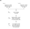
图2示出了根据某些实施方式用于估计心脏泵系统在患者中的位置的方法;Figure 2 illustrates a method for estimating the position of a heart pump system in a patient in accordance with certain embodiments;
图3示出了根据某些实施方式在一系列性能水平下运行的心脏泵系统的压差信号对电机电流的绘图;3 shows a plot of differential pressure signal versus motor current for a cardiac pump system operating at a range of performance levels in accordance with certain embodiments;
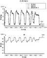
图4示出了根据某些实施方式在一个时间段内电机电流、压差信号和流量的绘图;4 shows a plot of motor current, differential pressure signal, and flow over a period of time in accordance with certain embodiments;
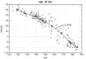
图5示出了根据某些实施方式心脏泵系统的压差信号对电机电流的绘图;5 shows a plot of a differential pressure signal versus motor current for a cardiac pump system in accordance with certain embodiments;
图6示出了根据某些实施方式第一阶段电机电流随时间的绘图;FIG. 6 shows a plot of first stage motor current over time in accordance with certain embodiments;
图7示出了根据某些实施方式第二阶段电机电流随时间的绘图;FIG. 7 shows a plot of second phase motor current over time in accordance with certain embodiments;
图8示出了根据某些实施方式第一和第二阶段心脏泵系统的压差信号对电机电流的绘图;FIG. 8 shows a plot of differential pressure signal versus motor current for a first and second stage cardiac pump system in accordance with certain embodiments;
图9示出了根据某些实施方式在一个时间段内第一阶段运行期间真实的、模拟的和模拟第一阶段压差信号的绘图;Figure 9 shows plots of real, simulated and simulated first stage differential pressure signals during first stage operation over a period of time in accordance with certain embodiments;
图10示出了根据某些实施方式在一个时间段内第二阶段运行期间真实的、模拟的和模拟第一阶段压差信号的绘图;10 shows plots of real, simulated, and simulated first-stage differential pressure signals during second-stage operation over a period of time in accordance with certain embodiments;
图11示出了根据某些实施方式当心脏泵系统的性能水平在两个水平之间变化时心脏泵系统的压差信号、电机电流和每分钟转数(RPM)的绘图;Figure 11 shows a plot of differential pressure signal, motor current, and revolutions per minute (RPM) of a heart pump system as the performance level of the heart pump system varies between two levels, according to certain embodiments;
图12示出了根据某些实施方式在一个时间段内在第一性能水平下压差信号和电机电流的绘图;FIG. 12 shows a plot of a differential pressure signal and motor current at a first performance level over a period of time in accordance with certain embodiments;
图13示出了根据某些实施方式在一个时间段内在第二性能水平下压差信号和电机电流的绘图;13 shows a plot of the differential pressure signal and motor current at a second performance level over a period of time in accordance with certain embodiments;
图14示出了根据某些实施方式压差信号漂移和电机电流随时间的绘图;FIG. 14 shows a plot of dropout signal drift and motor current over time in accordance with certain embodiments;
图15示出了根据某些实施方式在一个时间段内压差信号漂移和估计的压差信号的绘图;15 shows a plot of differential pressure signal drift and estimated differential pressure signal over a period of time in accordance with certain embodiments;
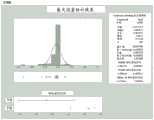
图16示出了根据某些实施方式平均流量估计误差的直方图;FIG. 16 shows a histogram of average flow estimation error in accordance with certain embodiments;
图17示出了根据某些实施方式最大流量估计误差的直方图;和Figure 17 shows a histogram of maximum flow estimation error in accordance with certain embodiments; and
图18示出了根据某些实施方式最小流量估计误差的直方图。Figure 18 shows a histogram of minimum flow estimation errors in accordance with certain embodiments.
具体实施方式Detailed ways
为了提供对本文描述的系统、方法和设备的总体理解,将描述某些示意性方面。尽管本文描述的方面和特征被特别地描述为结合患者心脏健康状况使用,但应理解,下文概述的所有部件和其他特征均可以任何合适的方式彼此组合并可改造和应用于其他类型的医学疗法和患者健康状况。In order to provide a general understanding of the systems, methods and apparatus described herein, certain illustrative aspects will be described. Although the aspects and features described herein are particularly described for use in connection with a patient's cardiac health condition, it should be understood that all components and other features outlined below may be combined with each other in any suitable manner and may be adapted and applied to other types of medical therapies and patient health.
本文描述的系统、设备和方法使用心脏泵系统中过去的电机电流数据与压差数据之间的关系从电机电流数据来确定时变压差的估计值。压差信号指示随着时间的压力,并且所显示的测量值可在泵的运行期间从血管内泵(如图1中的心脏泵100)上的压力传感器得出。例如,传感器可检测电信号(也称压差信号),该信号与泵外压力和泵内压力之间的差异成比例并且可由心脏泵系统显示。The systems, devices, and methods described herein use the relationship between past motor current data and differential pressure data in a heart pump system to determine an estimate of the time-varying differential pressure from the motor current data. The differential pressure signal is indicative of pressure over time, and the displayed measurements may be derived from a pressure sensor on an intravascular pump (such as
通过监测所测得的压力,临床医生可使用压差信号来确定泵在心脏内的定位以确定泵何时在心脏内处于正确布置。当将心脏泵跨过主动脉瓣放置在正确的位置中时,传感器的顶部(外表面)暴露于主动脉压力,而传感器的底部(内表面)暴露于心室压力。当心脏泵的套管跨越主动脉瓣使得泵的血液入口在左心室内而泵的出口在主动脉内时,可以认为心脏泵系统被正确地定位了。当心脏泵系统被正确地定位于心脏内时,与心动周期相关的压力变化会导致脉动压差信号。在心舒期期间,主动脉与左心室之间大的压力差异会产生大的压差信号。在心缩期的高峰,当主动脉瓣打开时,主动脉与左心室之间的压力差异(和因此压差信号)为零。因此,当被正确定位时,与心动周期相关的连续压力变化会产生脉动波形。当心脏泵系统未正确地跨过主动脉瓣放置时,或者当其完全在主动脉中或完全在心室中时,在整个心动周期中,套管外和套管内的压力将相同。结果,传感器膜任一侧上的压力相同,导致平坦的压差信号。例如,当正确放置时,压差信号可周期性地变化和/或具有为60mmHg、40mmHg或另一个通常高的值的峰谷值。当放置不正确时,压差信号可具有为0mmHg、2mmHg或另一个通常低的值的峰谷值。By monitoring the measured pressure, the clinician can use the differential pressure signal to determine the positioning of the pump within the heart to determine when the pump is properly positioned within the heart. When the heart pump is placed in the correct position across the aortic valve, the top (outer surface) of the sensor is exposed to aortic pressure and the bottom (inner surface) of the sensor is exposed to ventricular pressure. The heart pump system is considered to be correctly positioned when the cannula of the heart pump spans the aortic valve such that the blood inlet of the pump is in the left ventricle and the outlet of the pump is in the aorta. When the cardiac pump system is properly positioned within the heart, pressure changes associated with the cardiac cycle result in a pulsatile differential pressure signal. During diastole, a large pressure difference between the aorta and the left ventricle produces a large differential pressure signal. At the peak of systole, when the aortic valve opens, the pressure difference (and thus the differential pressure signal) between the aorta and the left ventricle is zero. Thus, when properly positioned, the continuous pressure changes associated with the cardiac cycle produce a pulsatile waveform. When the heart pump system is not properly placed across the aortic valve, or when it is entirely in the aorta or entirely in the ventricle, the pressure outside the cannula and inside the cannula will be the same throughout the cardiac cycle. As a result, the pressure on either side of the sensor membrane is the same, resulting in a flat differential pressure signal. For example, when properly placed, the differential pressure signal may vary periodically and/or have a peak-to-valley value of 60mmHg, 40mmHg, or another generally high value. When placed incorrectly, the differential pressure signal may have a peak-to-valley value of 0 mmHg, 2 mmHg, or another generally low value.
电机电流信号指示由心脏泵系统中的电机汲取的电流随时间的测量值。心脏泵系统(例如,心脏泵系统100)可设计为在特定的性能水平下提供恒定的心脏泵电机速度。操作心脏泵系统的电机(例如,容纳在图1的电机壳体102中)以如在许多医疗情况中所希望的那样维持恒定的转子速度通常需要向电机供给变化的电流量,因为在心脏的心动周期的不同阶段期间,电机上的载荷会变化。因此,当患者心脏中的压差变化时,电机电流也将改变以保持转子速度恒定。例如,当血液进入主动脉中的流率增加时(例如,在心缩期期间),运行电机所需的电流将增加。电机电流的此改变可因此用来帮助表征心脏功能,如将结合以下附图进一步讨论的。电机电流信号可从泵内的泵电机上、或者处理器或控制器本身内的传感器的测量值得出。即使在给定的时间不知道压差,也将知道此时的转子速度并将调节电机电流以确保转子速度稳定。本文描述的系统和方法在第一时间段期间对特定的心脏泵系统建立过去的电机电流与压差信号数据之间的关系,然后使用此关系来从在第二时间段期间新接收的电机电流数据确定估计的压差信号。对特定的心脏泵系统确定电机电流/压差信号关系,此关系指示该特定心脏泵系统的特征。The motor current signal is indicative of a measure of the current drawn by the motor in the heart pump system over time. A heart pump system (eg, heart pump system 100) can be designed to provide a constant heart pump motor speed at a particular performance level. Operating the motor of the heart pump system (eg, housed in the
一旦确定了电机电流与压差信号之间的关系,就使用电机电流来确定压差信号的估计值。然而,对于给定的电机电流值,可能存在两个可能的相应压差信号值:第一阶段(本文也称“阶段A”)值和第二阶段(本文也称“阶段B”)值。本文描述的系统和方法可确定心脏泵系统是处于阶段A还是阶段B,并相应地确定压差信号的估计值,这将在下文进一步描述。Once the relationship between the motor current and the differential pressure signal is determined, the motor current is used to determine an estimate of the differential pressure signal. However, for a given motor current value, there may be two possible corresponding differential voltage signal values: a first stage (also referred to herein as "Phase A") value and a second stage (also referred to herein as "Phase B") value. The systems and methods described herein may determine whether the heart pumping system is in Phase A or Phase B, and determine an estimate of the differential pressure signal accordingly, as described further below.
由于可使用电机电流和所述关系来确定时变压差的估计值,因此,如果压差传感器发生故障和由于漂移而使测得的压差信号数据不可用或不可靠,则本文描述的系统和方法可能特别有用,如下文关于图14-15所描述。在一些方面,可响应于压差传感器已发生故障的确定来确定时变压差的估计值。在一些方面,如果压差传感器发生故障,则心脏泵系统会发出警报。在一些方面,可不管压差传感器是否已发生故障都确定压差的估计值。通过比较测得的压差信号与估计的压差信号,本文描述的系统和方法也可用于确定测得的压差信号正在漂移而需要被重新校准。Since the motor current and the relationship can be used to determine an estimate of the time-varying differential pressure, if the differential pressure sensor fails and the measured differential pressure signal data is unavailable or unreliable due to drift, the system described herein will and methods may be particularly useful, as described below with respect to Figures 14-15. In some aspects, the estimate of the time-varying differential pressure may be determined in response to a determination that the differential pressure sensor has failed. In some aspects, the heart pumping system can issue an alarm if the differential pressure sensor fails. In some aspects, an estimate of the differential pressure may be determined regardless of whether the differential pressure sensor has failed. By comparing the measured differential pressure signal with the estimated differential pressure signal, the systems and methods described herein can also be used to determine that the measured differential pressure signal is drifting and needs to be recalibrated.
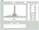
心脏泵系统至少部分地插入患者的心脏内。美国专利申请公开号2018-0078159-A1中公开了与本公开相容的心脏泵系统,其内容通过全文引用并入本文。通常,本公开可使用任何其他心脏泵系统或用于从患者获得生理学数据的系统。例如,压差信号和电机电流数据可显示在连接至心脏泵系统或作为心脏泵系统的一部分的界面如自动化Impella控制器(AIC)上。可从心脏泵系统信号提取原始特征。心脏泵系统可具有显示器,如显示心脏泵系统的实时运行数据的置入屏幕(placement screen)。这样的置入屏幕可在屏幕的中央显示区域中显示压差信号和电机电流波形以及每个波形的最大/最小和平均值。A heart pump system is inserted at least partially into the patient's heart. Heart pump systems compatible with the present disclosure are disclosed in US Patent Application Publication No. 2018-0078159-A1, the contents of which are incorporated herein by reference in their entirety. In general, the present disclosure may use any other cardiac pump system or system for obtaining physiological data from a patient. For example, the differential pressure signal and motor current data can be displayed on an interface such as an Automated Impella Controller (AIC) connected to or as part of a cardiac pump system. Raw features can be extracted from the cardiac pump system signal. The heart pump system may have a display, such as a placement screen that displays real-time operational data of the heart pump system. Such a drop-in screen displays the differential pressure signal and motor current waveforms along with the maximum/minimum and average values of each waveform in the central display area of the screen.
在一些实施方式中,本文描述的系统和方法可涉及IMPELLA®系列设备(Abiomed,Inc., Danvers MA)的Impella 5.0设备。In some embodiments, the systems and methods described herein may involve the Impella 5.0 device of the IMPELLA® series of devices (Abiomed, Inc., Danvers MA).
图1示出了根据某些实施方式插入到患者的血管中并配置为估计心血管参数的示意性心脏泵系统。心脏泵系统100可在心脏内、部分地在心脏内、在心脏外、部分地在心脏外、部分地在血管系统外或在患者的血管系统中的任何其他合适的位置中运行。当套管173跨过主动脉瓣放置使得泵的血液入口(例如,血液入口172)在左心室内而泵的出口(例如,出口开口170)在主动脉内时,心脏泵系统可视为“就位”。心脏泵系统100包括心脏泵106和控制系统104。控制系统104的全部或部分可在与心脏泵106分开/远程的控制器单元中。在一些实施方式中,控制系统104在心脏泵106内部。控制系统104和心脏泵106未按比例绘制。泵系统100包括细长导管主体105、电机壳体102和其中形成有泵元件的驱动轴。泵100包括泵壳体134、和在电机壳体102的远端111处联接至套管173的电机壳体102。驱动轴上的叶轮叶片可在泵壳体134内旋转以引起血液在抽吸头174处向套管173中的流动。抽吸头174在套管173的远端部分171处提供血液入口172。血液流109沿第一方向108通过套管173并在套管173的一个或多个出口开口170处离开套管173。1 illustrates an illustrative heart pump system inserted into a blood vessel of a patient and configured to estimate cardiovascular parameters, according to certain embodiments. The
驱动轴在泵壳体134内的旋转也可使泵元件在轴承间隙内旋转。血液相容性流体可通过细长导管105递送穿过电机壳体102到套管173的近端部分,在这里,流体通过泵元件的旋转而被加压。血液相容性流体的流动具有穿过泵的轴承间隙的第二方向122。在离开轴承间隙后,血液相容性流体可遵循流动方向123并被夹带在血液流中并随血液流入主动脉中。Rotation of the drive shaft within the
心脏泵100通过护套175插入到患者的血管中。泵壳体134可包围转子和内部轴承并且可定尺寸以经皮插入到患者的血管中。在一些实施方式中,泵可被推进通过脉管系统并到主动脉弓164上方。尽管泵示出为在左心室中,但泵可替代地放置在右心中,使得血液从患者的下腔静脉或右心房泵出,通过右心室进入到肺动脉中。The
也可在抽吸头174的远端、套管173的远端部分171处包括挠性突出部176,以便将心脏泵100最佳地定位在心脏的血管或腔室中。挠性突出部176可防止抽吸头174靠近血管壁,在血管壁,其可能由于抽吸而被卡住。挠性突出部176可以机械方式而非液力方式延伸泵100,因为挠性突出部176可以是非抽吸的。在一些实施方式中,挠性突出部可形成为猪尾状。在一些方面,泵不需要包括挠性突出部。A
细长导管105容纳连接件126,该连接件126可包含流体供给管线并还可容纳电连接电缆。连接件126可从可包含在控制系统104内的流体贮存器向泵供给血液相容性流体。The
控制系统104包括控制器182,其控制泵106,包括例如控制输入到电机的功率或控制电机速度,还可包括心脏参数估计器116。在一些实施方式中,控制系统104包括显示屏以显示测量值如压差信号和电机电流。控制系统104可包括电路以监测电机电流中指示管线中的空气的电流下降、压差信号的变化、流动位置、抽吸或任何其他合适的测量值。控制系统104可包括警告音、光或指示器以给操作人员报警传感器故障、连接件126中的中断或破裂、或患者健康状况的突然变化。The
控制系统104可包括电流传感器(未示出)。控制器182通过连接件126如通过一根或多根电线向电机108供给电流。经由连接件126供给到电机108的电流通过电流传感器测量。机械泵的电机承受的载荷为压头,或主动脉压力与左心室压力之间的差异。对于给定的压头,心脏泵106在稳态运行期间将承受标称载荷,并且该标称载荷的变化是由于改变外部载荷条件,例如左心室收缩的动力学。动态载荷条件的变化会改变以恒定或基本上恒定的速度运行泵转子所需的电机电流。电机可在将转子维持在设定速度下所需的速度下运行。结果并如下文进一步描述的,可监测电机汲取的用于维持转子速度的电机电流并用来理解潜在的心脏状态。通过使用压力传感器112在心动周期期间同时监测压头,可甚至更精确地量化和理解心脏状态。心脏参数估计器185接收来自电流传感器的电流信号以及来自压力传感器112的压力信号。心脏参数估计器185使用这些电流和压力信号来表征心脏的功能。心脏参数估计器185可访问存储的查找表以获得基于压力和电流信号来表征心脏功能的附加信息。例如,心脏参数估计器185可从压力传感器112接收主动脉压力,并且使用查找表,可使用主动脉压力来确定Δ压力。The
压力传感器为集成在套管172中的挠性膜。如上所述,传感器的一侧暴露于套管外部上的血液压力而另一侧暴露于套管内部的血液压力。传感器生成与套管外部压力和内部压力之间的差异成比例的电信号(压差信号),该信号可由心脏泵系统显示。当将心脏泵系统跨过主动脉瓣放置在正确的位置中时,传感器的顶部(外表面)暴露于主动脉压力,而传感器的底部(内表面)暴露于心室压力。因此,压差信号近似等于主动脉压力与心室压力之间的差异。The pressure sensor is a flexible membrane integrated in the
图2示出了根据某些实施方式用来基于电机电流确定时变压差的估计值的方法200。方法200可使用任何合适的心脏泵系统来执行,如图1中所描述的。在步骤210中,接收指示第一时间段期间的时变电机电流的第一数据。该第一数据(也称电机电流数据)可以是电机电流信号的一部分。如上所述,电机电流数据描述了心脏泵系统中递送到电机的电流。例如,电机可以维持转子恒定或基本上恒定的旋转速度所必需的旋转速度运行。可使用电流传感器(例如,关于图1描述的电流传感器)或通过任何其他合适的手段来测量电流。在步骤212中,接收指示第一时间段期间的时变压差的第二数据。该第二数据(也称压差信号数据)可以是压差信号的一部分。在一些实施方式中,压差信号数据描述由压差传感器(例如,压力传感器112)测量的压力的变化。压差传感器可以是光学压力传感器、电压力传感器、MEMS传感器或任何其他合适的压力传感器。临床医生可使用压差信号来监测心脏泵相对于患者主动脉瓣的位置。压差信号和电机电流信号可显示给临床医生或心脏泵系统的其他操作人员。在一些方面,从心脏泵系统接收或获取第一数据和第二数据,该心脏泵系统在第一时间段期间可至少部分地位于患者的心脏内。FIG. 2 illustrates a
确定该心脏泵系统的压差与电机电流之间的关系。如上所述,使用训练数据来确定该关系,训练数据可包括在步骤210和212中接收的电机电流数据和压差信号数据。在一些方面,在心脏泵系统在单个P-水平下运行的同时获取电机电流数据和压差信号数据。P-水平为心脏泵系统的性能水平并与系统的流量控制有关,代表电机速度。随着P-水平增加,与心脏泵系统相关的流率、电机电流和每分钟转数也增加。例如,电机电流数据和压差信号数据可各包含对应于相同的40秒时间段的1000个样本点(实时数据收集的频率为25Hz),在此期间心脏泵系统在P-水平P-8下运行。Determine the relationship between the differential pressure and motor current for the heart pump system. As described above, the relationship is determined using training data, which may include motor current data and differential pressure signal data received in
本文描述的系统和方法可计算代表训练数据的模型。在一些方面,本文描述的系统和方法通过相对于电机电流数据值绘制压差信号数据值和/或确定所得曲线的多线性回归,来计算电机电流与压差信号之间的代表性关系。该曲线和相关的多线性回归代表电机电流数据和压差信号数据所获取自的心脏泵系统的电机电流与压差信号之间的关系。该曲线和相关的多线性回归可指示第一数据和第二数据(分别与电机电流和压差有关)所获取自的特定心脏泵系统的运行特性。例如,这些运行特性可包括最小和最大压差、最小和最大电机电流以及在给定性能水平下运行的第一和第二阶段之间的拐点。The systems and methods described herein can compute models that represent training data. In some aspects, the systems and methods described herein calculate a representative relationship between the motor current and the differential pressure signal by plotting the differential pressure signal data values against the motor current data values and/or determining a multiple linear regression of the resulting curve. The curve and the associated multiple linear regression represent the relationship between the motor current and the differential pressure signal of the cardiac pump system from which the motor current data and the differential pressure signal data were obtained. The curve and associated multiple linear regression can be indicative of the operating characteristics of the particular heart pump system from which the first data and the second data (related to motor current and differential pressure, respectively) were obtained. For example, these operating characteristics may include minimum and maximum voltage differentials, minimum and maximum motor currents, and the inflection point between the first and second phases of operation at a given performance level.
在任选的步骤216中,本文描述的系统和方法确定压力传感器已发生故障。在一些方面,当系统不再接收任何压差信号数据时,或者当在第二时间段期间没有从压差传感器接收到任何数据时,所述系统和方法可确定压力传感器已发生故障。在一些方面,本文描述的系统和方法可确定压力传感器需要被重新校准,如下文关于图14-15更详细地描述的。在确定压力传感器需要被重新校准后,可依赖于压差信号的估计值(如下文在步骤220中所述)而不是所测得的压差信号进行进一步的计算,如抽吸、流量和位置。In
在步骤218中,接收指示在比第一时间段晚的第二时间段期间的时变电机电流的第三数据。该第三数据(下文称为附加电机电流数据)由如上文关于步骤210的电机电流数据所述的同一心脏泵系统的同一传感器测量。附加电机电流数据可代表在步骤210中接收的电机电流数据所代表的时间段之后的时间段。在一些方面,可能已在与步骤210的电机电流数据不同的P-水平下获取了附加电机电流数据。例如,附加电机数据可代表期间心脏泵系统在P-水平P-6下运行的2秒时间段。In
在步骤220中,从第三数据及上述第一数据(电机电流数据)与第二数据(压差信号数据)之间的关系确定第二时间段期间的时变压差的估计值。如果用于收集电机电流数据和压差信号数据的P-水平与用于收集附加电机电流数据的P-水平不同,则必须缩放所述关系来顾及P-水平的变化,如下文关于图4所描述。一旦所述关系被缩放,则本文描述的系统和方法将针对附加电机电流数据确定心脏泵系统是处于“阶段A”还是“阶段B”中,如下文关于图3所描述。阶段确定取决于心动周期的心舒期开始和结束期间的电机电流值,后者取决于患者压力和P-水平。然后,每个附加电机电流数据值都映射到相应的阶段A或阶段B压差信号值。在一些实施方式中,此模拟几乎实时发生并可显示给心脏泵系统的操作人员。如果压力传感器已发生故障,则可显示估计的压差信号而不是测得的压差信号,使得即使压力传感器发生故障,临床医生仍可查看压差信号数据。在一些方面,心脏泵系统可显示指示压差传感器已发生故障或不可靠的通知。在一些方面,心脏泵系统可显示指示时变压差的估计值被模拟和/或心脏泵系统正在显示压差信号的估计值而不是测得的压差信号的通知。In
准确的压差信号不仅可用于在患者内正确地定位心脏泵系统,而且可用于确定其他指标如流量、位置、抽吸、漂移和心输出量(其可从流量计算)。流量为通过心脏泵系统中的泵的血液流率。流量可用于计算患者的心输出量并提供心脏泵提供给心脏的机械辅助的量度。通过健康心脏的血液流量平均为约5升/分钟,通过心脏泵系统的血液流量可以是相似或不同的流率。当可用于心脏泵系统的血液体积不足或受限时,就会发生抽吸。抽吸的监测非常重要,因为它将限制心脏泵系统可提供的支持量并可能表明心脏泵被阻塞,例如,如果泵的入口区域贴嵌患者组织。位置是心脏泵在患者心脏内的实际定位,这对心脏泵系统的正确运行很重要。漂移是当测得的压差信号从预期值或恒定值向上或向下漂移时。如果压差信号开始漂移,则可能需要重新校准压力传感器。在一些实施方式中,系统可确定压力传感器需要被重新校准并且系统可向用户显示警告或信号以相应地重新校准或者可自动重新校准传感器。An accurate differential pressure signal can be used not only to properly position the cardiac pump system within the patient, but also to determine other metrics such as flow, position, aspiration, drift and cardiac output (which can be calculated from flow). Flow is the rate of blood flow through the pumps in the heart pumping system. Flow can be used to calculate the patient's cardiac output and provide a measure of the mechanical assistance the heart pump provides to the heart. Blood flow through a healthy heart averages about 5 liters per minute, and blood flow through the heart's pumping system can be at similar or different flow rates. Aspiration occurs when the volume of blood available to the heart's pumping system is insufficient or limited. Monitoring of aspiration is important because it will limit the amount of support the heart pumping system can provide and may indicate obstruction of the heart pump, for example, if the inlet area of the pump is embedded in the patient's tissue. Position is the actual positioning of the cardiac pump within the patient's heart, which is important for the correct functioning of the cardiac pumping system. Drift is when the measured differential pressure signal drifts up or down from an expected or constant value. If the differential pressure signal begins to drift, the pressure sensor may need to be recalibrated. In some embodiments, the system may determine that the pressure sensor needs to be recalibrated and the system may display a warning or signal to the user to recalibrate accordingly or may automatically recalibrate the sensor.
如上文所提到,压差信号可用于确定心脏泵系统是否正确地定位于患者心脏中。当心脏泵系统跨过主动脉瓣正确地定位时,与心动周期相关的压力变化会导致脉动压差信号。当心脏泵系统未正确地跨过主动脉瓣放置时,或者当其完全在主动脉中或完全在心室中时,在整个心动周期中,套管外和套管内的压力将相同。结果,传感器膜任一侧上的压力相同,导致平坦的压差信号。然而,如果压差信号不可靠,则临床医生可能难以确定系统是否正确定位,在这种情况下,估计的压差信号将非常有用。As mentioned above, the differential pressure signal can be used to determine whether the cardiac pump system is properly positioned in the patient's heart. When the heart pumping system is properly positioned across the aortic valve, pressure changes associated with the cardiac cycle result in a pulsatile differential pressure signal. When the heart pump system is not properly placed across the aortic valve, or when it is entirely in the aorta or entirely in the ventricle, the pressure outside the cannula and inside the cannula will be the same throughout the cardiac cycle. As a result, the pressure on either side of the sensor membrane is the same, resulting in a flat differential pressure signal. However, if the differential pressure signal is unreliable, it may be difficult for the clinician to determine whether the system is positioned correctly, in which case the estimated differential pressure signal would be very useful.
心脏泵系统可运行以取得最大的可能流量而不引起抽吸。流率可能因不正确的定位或抽吸而变化。如果可用于心脏泵的血液体积不足或受限,则心脏泵系统可能触发抽吸警报。抽吸将限制心脏泵系统可为患者提供的支持量,从而导致动脉压和心输出量的降低;可损坏血细胞,从而导致溶血;也可能是右心衰竭的指标。因此,在心脏泵系统的运行期间监测抽吸是很重要的。The cardiac pump system can operate to achieve the maximum possible flow without causing aspiration. Flow rate may vary due to incorrect positioning or aspiration. The heart pumping system may trigger a suction alarm if the volume of blood available for the heart pump is insufficient or limited. Suction will limit the amount of support the heart's pumping system can provide to the patient, resulting in a decrease in arterial pressure and cardiac output; can damage blood cells, leading to hemolysis; and may be an indicator of right heart failure. Therefore, it is important to monitor aspiration during operation of the cardiac pump system.
图3-18进一步示意了本公开的各种实施方式和实例结果。图3示出了在不同的性能水平下特定心脏泵的压差与电机电流之间的关系的实例。图3中示出的曲线是使用电机电流和压差信号数据计算的,如上文关于步骤210和212所描述的数据。图4示出了上文关于步骤210和212所描述的训练数据的实例。图5示出了在单个性能水平下的特定心脏泵仅在第一阶段中运行的压差与电机电流之间的关系的实例。图6示出了在第一阶段的运行期间电机电流数据的实例,如上文关于步骤210所描述的那些。图7示出了在第二阶段的运行期间电机电流数据的实例,如上文关于步骤210所描述的那些。图8示出了在单个性能水平下的特定心脏泵第一阶段和第二阶段二者的压差与电机电流之间的关系的实例。图8中示出的曲线可为图3中示出的多个曲线中之一的实例。图9-10示出了测得的压差信号数据和压差信号的估计值,如上文分别关于步骤218和220所描述的。图11示出了测得的压差信号、压差信号的估计值(如步骤220中所描述的)、电机电流(如步骤218中所描述的)和心脏泵电机的转子的每分钟转数(如上文关于图1所描述的)。图12-13示出了测得的压差信号、压差信号的估计值(如步骤220中所描述的)和电机电流(如步骤218中所描述的),它们得自在第一P-水平下的训练及在第一和第二P-水平下的测试。图14-15示出了测量压差信号与电机电流数据(如步骤210或步骤218中那些)和压差信号的估计值(如步骤220中的那些)相比较的漂移。如下文将关于图14-15进一步描述的,估计的压差信号也可用于确定压差信号是正在漂移还是已经漂移,以及传感器是否需要被重新校准。图16-18示出了使用估计的压差信号(如步骤220中的那些)计算的流率估计值与使用测得的压差信号计算的流率相比的效验。3-18 further illustrate various embodiments of the present disclosure and example results. Figure 3 shows an example of the relationship between differential pressure and motor current for a particular heart pump at different performance levels. The curves shown in FIG. 3 are calculated using the motor current and differential pressure signal data, as described above with respect to
图3示出了根据某些实施方式在九种不同的性能水平下运行的心脏泵系统的压差信号对电机电流的绘图300。绘图300的y-轴代表以mmHg为单位的压差信号,而x-轴代表以mA为单位的电机电流。每条曲线P-1至P-9指示在不同性能水平或P-水平下运行的同一心脏泵系统的代表性曲线(例如,曲线P-1对应于运行性能水平P-1),性能水平与心脏泵系统的流量控制有关。较高的P-水平对应于与心脏泵系统相关的较高流率和每分钟转数。3 shows a
如图3中所描绘,心脏泵系统的压差与电机电流之间的关系随性能水平缩放。因此,如果给定心脏泵系统的压差与电机电流之间的关系是在第一P-水平(例如,P-8)下确定的,则可缩放该心脏泵系统的压差与电机电流之间的关系来确定在第二P-水平(例如,P-6)下该心脏泵系统的压差与电机电流之间的关系。例如,在图3中所示的情况下,在P-8下收集心脏泵系统的压差信号和电机电流数据。该数据部分地由点310、312、314、316、318代表。虚线302、304、308代表压差与电机电流之间的关系的线性缩放。具体而言,线302代表P-水平之间最大压差信号的线性缩放。随着P-水平增大,最大压差信号增大。线304代表P-水平之间压差与电机电流之间的关系的拐点的线性缩放。随着P-水平增大,拐点线性增大。线308代表P-水平之间最小压差信号的线性缩放。随着P-水平增大,最小压差信号减小。例如,通过确定P-8下的最大压差信号、最小压差信号和拐点,可计算P-1至P-7和P-9的最大压差信号、最小压差信号和拐点。在一些实施方式中,可使用缩放因子来实现P-水平之间的缩放。为了确定缩放因子,对一系列N个心脏泵系统找出在所有P-水平下的最大值、最小值和拐点。所有N个心脏泵系统为在相似条件下运行的同一种心脏泵系统。对所有N个心脏泵系统数据计算所有P-水平间的最大值、最小值和拐点的线性拟合。然后将这些线性拟合用于确定所述N个心脏泵系统的最大值、最小值和拐点的缩放因子。所述N个泵的这三个缩放因子非常相似,然后取它们的平均值来确定该泵类型的所有泵的通用缩放因子。As depicted in Figure 3, the relationship between differential pressure and motor current of the cardiac pump system scales with performance level. Thus, if the relationship between differential pressure and motor current for a given heart pumping system is determined at a first P-level (eg, P-8), the ratio of differential pressure and motor current for that heart pumping system can be scaled to determine the relationship between the differential pressure of the cardiac pump system and the motor current at a second P-level (eg, P-6). For example, in the case shown in Figure 3, the differential pressure signal and motor current data for the cardiac pump system were collected at P-8. This data is represented in part by
如从曲线P-1至P-9中的每一条可见,对于给定的电机电流值,即使对于单个性能水平曲线,也可能存在多个相应的压差信号值。单个电机电流值的相应压差信号值被归类为“阶段A”或“阶段B”。P-1至P-9在拐点线304上方的绘制值被归类为阶段B值。P-1至P-9在拐点线304下方的绘制值被归类为阶段A值。例如,点310、312、314、316、318为P-水平P-8的阶段A值。如上所述,当确定时变压差的估计值时,本文描述的系统和方法确定电机电流信号是处于阶段A还是阶段B中,并相应地确定压差信号值的相应估计值。例如,如果在P-水平P-8下运行时测得的电机电流为600mA,则如果测得的电机电流在阶段A中,相应的压差信号值将为42mmHg,而如果测得的电机电流在阶段B中,相应的压差信号值将为110mmHg。下面关于图6-7描述从测得的电机电流值区分阶段A和阶段B的方法。As can be seen from each of curves P-1 to P-9, for a given motor current value, even for a single performance level curve, there may be multiple corresponding differential pressure signal values. The corresponding differential pressure signal values for individual motor current values are classified as "Phase A" or "Phase B". The plotted values of P-1 to P-9 above the
图4示出了根据某些实施方式电机电流、压差信号和流量随时间的绘图。绘图410的y-轴指示以毫安(mA)为单位测得的电机电流,绘图420的y-轴指示以毫米汞柱(mmHg)为单位测得的压差信号,绘图430的y-轴指示以升每分钟(L/m)为单位的流量。绘图410、420、430代表相同的时间段,沿各绘图的相应x-轴以样本数为单位测量。这些绘图以某种周期性的方式变化,使得每个绘图具有交替的峰和谷。电机电流410的峰对应于压差信号420的谷和流量430的峰。例如,在100个样本标记处,电机电流410处于局部最大,而同时压差信号420处于局部最小。4 shows a plot of motor current, differential pressure signal, and flow over time in accordance with certain embodiments. The y-axis of
绘图410和420分别代表对单个心脏泵系统从电流传感器和压力传感器测得的数据,如上文关于图1所描述的。沿绘图的每个“点”代表一个测得的数据点。将测得的数据点最佳拟合以提供绘图410和420。将由绘图410和420代表的数据如上所述用作训练数据,以建立代表心脏泵系统的压差与电机电流关系之间的关系的模型。
图5示出了根据某些实施方式特定心脏泵系统的压差信号对电机电流的绘图。绘图500的y-轴代表以mmHg为单位的压差信号,而x-轴代表以mA为单位的电机电流。在特定的时间点,对特定的心脏泵测量压差信号和电机电流。这两个测量值在绘图500中由点表示。例如,来自图4的绘图410和420的数据点可如上所述由绘图500中的点代表。可使用多线性近似来确定最佳拟合曲线510以代表训练数据。最佳拟合曲线510代表在此情况下用于获取图4和5中所示的数据的特定心脏泵系统。Figure 5 shows a plot of the differential pressure signal versus motor current for a particular heart pump system, according to certain embodiments. The y-axis of the
从描绘电机电流随时间的绘图,如图6和7,本文描述的系统和方法可确定心脏泵系统是处于阶段A还是阶段B中。心舒期的起始点和结束点之间的直线的斜率指示系统是处于阶段A还是阶段B中。正斜率指示阶段A,而负斜率指示阶段B。在阶段B中,局部电机电流最小值直接发生在心缩期之前,而在阶段A中,局部电机电流最小值直接发生在心缩期之后。心脏泵系统是处于阶段A还是阶段B中取决于患者压力和P-水平。阶段B更可能发生在较低的P-水平(和较低的电机电流值)下。较高的压差信号值发生在阶段B中。From plots depicting motor current over time, such as Figures 6 and 7, the systems and methods described herein can determine whether the heart pumping system is in Phase A or Phase B. The slope of the line between the start and end points of diastole indicates whether the system is in phase A or phase B. A positive slope indicates phase A, while a negative slope indicates phase B. In phase B, the local motor current minimum occurs directly before systole, while in phase A, the local motor current minimum occurs directly after systole. Whether the heart pumping system is in Phase A or Phase B depends on patient pressure and P-level. Phase B is more likely to occur at lower P-levels (and lower motor current values). Higher differential pressure signal values occur in phase B.
图6示出了根据某些实施方式阶段A电机电流随时间的绘图。绘图600的y-轴代表以mA为单位的电机电流,而x-轴代表以样本数为单位的时间。圆圈602指示心舒期的开始。圆圈604指示心舒期的结束。圆圈602和604之间的斜率是正的,指示心脏泵系统处于阶段A中。6 shows a plot of Phase A motor current over time in accordance with certain embodiments. The y-axis of the
图7示出了根据某些实施方式阶段B电机电流随时间的绘图。绘图700的y-轴代表以mA为单位的电机电流,而x-轴代表以样本数为单位的时间。圆圈702指示心舒期的开始。圆圈704指示心舒期的结束。圆圈602和604之间的斜率是负的,指示心脏泵系统处于阶段B中。7 shows a plot of Phase B motor current over time in accordance with certain embodiments. The y-axis of
图8示出了根据某些实施方式心脏泵系统的压差信号对电机电流的绘图。绘图800的y-轴代表以mmHg为单位的压差信号,而x-轴代表以mA为单位的电机电流。线810划定了710mA的电机电流值。在大约50mmHg处的拐点840指示从阶段A向阶段B的“变化”。拐点840以上的点在阶段B中,而拐点840以下的点在阶段A中。在较高的电机电流值(高于大约730mA)下,心脏泵系统将在阶段A中运行而不再有相应的阶段B值。圆圈820和830指示对应于线810所指示的710mA电机电流值的两个可能的压差信号值。圆圈820指示大约40mmHg的值并在阶段A中。圆圈830指示大约90mmHg的相应阶段B值。8 shows a plot of a differential pressure signal versus motor current for a cardiac pump system in accordance with certain embodiments. The y-axis of the
图9示出了根据某些实施方式真实的、模拟的和模拟阶段A压差信号随时间的绘图。绘图900的y-轴代表以mmHg为单位的压差信号,而x-轴代表以样本数为单位的时间。曲线910示出了如由心脏泵系统的压差传感器所测得的压差信号。模拟的压差信号曲线是估计的压差信号,如由本文描述的系统和方法所模拟,并与曲线912完全重叠。因此,模拟的曲线在绘图900中不可见。曲线912指示根据本文描述的系统和方法的“阶段A”压差信号模拟。模拟阶段A压差信号912与模拟的压差信号完全匹配,因为心脏泵系统在此时帧期间完全在阶段A中运行,这可由心舒期期间的正斜率所证实。绘图900可用于验证模拟的压差信号的性能。如在绘图900中可见,真实的压差信号910和模拟的压差信号912匹配非常紧密。两个信号910和912的周期、平均值、最大值和最小值尤其接近。这些值是在流量、定位和抽吸计算中使用的重要指标。压差信号最小值用于确定流量最大值;压差信号最大值用于确定流量最小值;压差信号平均值用于确定流量平均值。流量平均值、最大值和最小值可通过用户界面显示给临床医生。9 shows plots of real, simulated, and simulated Phase A differential pressure signals over time, in accordance with certain embodiments. The y-axis of the
图10示出了根据某些实施方式真实的、模拟的和模拟阶段A压差信号随时间的绘图。绘图1000的y-轴代表以mmHg为单位的压差信号,而x-轴代表以样本数为单位的时间。曲线1010示出了如由心脏泵系统的压差传感器所测得的压差信号。曲线1012示出了估计的压差信号,如由本文描述的系统和方法所模拟。曲线1014与曲线1012部分地重叠并指示根据本文描述的系统和方法的“阶段A”压差信号模拟。模拟阶段A压差信号1014和模拟的压差信号1012不完全匹配(主要在峰周围偏离),因为心脏泵系统在此时帧期间至少部分地在阶段B中运行,这可由舒张周期期间的负斜率所证实。绘图1000证明了确定心脏泵系统是在阶段A还是阶段B中运行的重要性。虽然模拟阶段A信号1014非常紧密地匹配了周期和最小真实值,但其并不匹配最大或平均值,后者由压差传感器测得并在曲线1010中示出。虽然模拟的曲线1012并不与真实信号1010完全重叠,但它通过考虑阶段B而提供真实压差信号(尤其是最小和最大值)足够好的估计,这可用于流量计算和位置/抽吸警报。10 shows plots of real, simulated, and simulated Phase A differential pressure signals over time, in accordance with certain embodiments. The y-axis of the
图11示出了根据某些实施方式当心脏泵系统的性能水平已变化时心脏泵系统的压差信号、电机电流和每分钟转数(RPM)随时间的绘图。绘图1110示出了压差信号验证,绘图1120示出了随时间的电机电流,而绘图1130示出了随时间的RPM。三个绘图1110、1120、1130指示在相同的时间段内运行的同一心脏泵系统的同时测量值。绘图1110的y-轴代表以mmHg为单位的压差信号,而x-轴代表以样本数为单位的时间。曲线1112代表由压差传感器测得的压差信号。曲线1114代表压差信号的估计值。绘图1120的y-轴代表以mA为单位的电机电流,而x-轴代表以样本数为单位的时间。曲线1122代表如由心脏泵系统测得的随时间的电机电流。绘图1130的y-轴代表RPM,而x-轴代表以样本数为单位的时间。曲线1132代表如由心脏泵系统测得的随时间的RPM。框1116、1126、1136表示心脏泵系统在第一P-水平下的运行时间段。框1118、1128、1138表示心脏泵系统在第二P-水平下的运行时间段。第二P-水平低于第一P-水平。一旦在框1116、1126、1136与框1118、1128、1138之间降低了P-水平,则RPM和电机电流全部减小。11 shows a plot of differential pressure signal, motor current, and revolutions per minute (RPM) of a heart pump system over time when the performance level of the heart pump system has changed, according to certain embodiments.
如由图11-13所代表,心脏泵系统在第一P-水平下运行以获取包括电机电流和压差信号数据的训练数据。训练数据用于确定在该P-水平下电机电流与压差信号数据之间的关系。然后用该关系来确定框1116中由曲线1114示出的压差信号的估计值,其与由曲线1112示出的测得的压差信号紧密匹配。然后在较低的第二P-水平下运行心脏泵系统。缩放压差与电机电流之间的关系来顾及该较低的P-水平,如上文关于图3所描述。然后使用该经缩放的确定的关系来确定在此第二P-水平下的估计的压差信号。如框1118中所示,估计的压差信号1114再次与测得的压差信号1112紧密匹配。As represented by Figures 11-13, the heart pump system operates at a first P-level to acquire training data including motor current and differential pressure signal data. The training data is used to determine the relationship between the motor current and the differential pressure signal data at this P-level. This relationship is then used to determine an estimate of the differential pressure signal shown by
图12示出了根据某些实施方式在第一P-水平下压差信号和电机电流随时间的绘图。绘图1210为如图11中所示框1116的放大视图。绘图1210的y-轴示出了以mmHg为单位测量的压差信号。绘图1220为如图11中所示框1126的放大视图。绘图1220的y-轴示出了以mA为单位测量的电机电流。绘图1210和1220的x-轴示出了相同的时间段以样本数为单位测量的时间。绘图1210显示了测得的压差信号曲线1212、模拟的布置曲线1214和模拟阶段A压差信号曲线1216。模拟阶段A压差信号曲线1212与模拟的压差信号曲线1214几乎重叠,表明压差估计是准确的。12 shows a plot of the differential pressure signal and motor current over time at a first P-level, according to certain embodiments. Drawing 1210 is an enlarged view of
图13示出了根据某些实施方式在第二P-水平下压差信号和电机电流随时间的绘图。绘图1310为如图11中所示框1118的放大视图。绘图1310的y-轴示出了以mmHg为单位测量的压差信号。绘图1320为如图11中所示框1128的放大视图。绘图1220的y-轴示出了以mA为单位测量的电机电流。绘图1310和1320的x-轴示出了相同的时间段以样本数为单位测量的时间。绘图1310显示了测得的压差信号曲线1312、模拟的布置曲线1314和模拟阶段A压差信号曲线1316。模拟阶段A压差信号曲线1312与模拟的压差信号曲线1314几乎重叠,表明压差估计是准确的。13 shows a plot of the differential voltage signal and motor current over time at a second P-level, according to certain embodiments. Drawing 1310 is an enlarged view of
尽管尚未使用在第二P-水平下获取的训练数据“建立”压差与电机电流之间的关系,但估计的压差信号1314仍与在该P-水平下测得的压差信号1312紧密匹配。这些结果表明,当在P-水平之间切换时使用的缩放过程是可靠的并提供与在用于训练的P-水平下测得的结果同等的结果。Although the relationship between the differential pressure and motor current has not been "established" using the training data acquired at the second P-level, the estimated
图14示出了根据某些实施方式压差信号漂移和电机电流随时间的绘图。绘图1410的y-轴代表以mmHg为单位的压差信号,而x-轴代表以样本数为单位的时间。绘图1420的y-轴代表以mA为单位的电机电流,而x-轴代表在与绘图1410中所代表的相同时间段内以样本数为单位的时间。电机电流1420随时间保持,在整个时间段内具有大致相同的平均值。在此相同时间段期间,压差信号(如由压力传感器所测得)显著增大,从大约20mmHg的平均值增至大约80mmHg的平均值。当平均电机电流值在相当长的时间段内是稳定的时,平均压差信号在该时间段内也应是稳定的。在这种情况下,压差信号1410正在“漂移”,表明压力传感器不再提供准确的测量值。FIG. 14 shows a plot of dropout signal drift and motor current over time in accordance with certain embodiments. The y-axis of
图15示出了根据某些实施方式压差信号漂移和估计的压差信号随时间的绘图。绘图1500的y-轴代表以mmHg为单位的压差信号,而x-轴代表以样本数为单位的时间。曲线1510代表测得的压差信号,曲线1512代表测得的压差信号的平均值,曲线1514代表模拟的压差信号,而曲线1516代表模拟的压差信号的平均值。测得的压差信号1510正在漂移,而压差信号的估计值(模拟的压差信号) 1514保持稳定。如果测得的压差信号偏离模拟的压差信号,特别是在平均测得的压差信号1512与模拟的平均压差信号1516紧密匹配的时间段之后,本文描述的系统和方法可确定压力传感器(提供测得的压差信号数据)需要被重新校准。在一些实施方式中,传感器可被自动重新校准。在一些方面,心脏泵系统可向用户显示指示传感器需要被重新校准的通知。15 shows a plot of differential pressure signal drift and estimated differential pressure signal over time in accordance with certain embodiments. The y-axis of the plot 1500 represents the differential pressure signal in mmHg, while the x-axis represents time in the number of samples.
在一些实施方式中,为了确定压差信号是否正在漂移,本文描述的系统和方法可计算压差信号或压差信号的平均值(例如,曲线1512)与压差信号的估计值(例如,曲线1516)或估计值的平均值之间的差异。可将该差异与阈值进行比较。如果差异超过阈值,则压差信号已漂移。如果差异低于阈值,则压差信号尚未漂移。阈值可为10mmHg、20mmHg或任何合适的量。例如,阈值可为15mmHg,则在图15中曲线1512可确定为在样本4.000e+4处漂移。在一些实施方式中,系统可确定在第一时间测得的压差信号与估计值之间的第一差异和在第二时间测得的压差信号与估计值之间的第二差异。如果第二差异显著大于第一差异,则系统可确定测得的压力信号已漂移。在一些实施方式中,可周期性地或连续地监测测得的压差信号与估计值之间的差异。如果差异随时间增加,则系统可确定测得的压力信号正在漂移。In some embodiments, in order to determine whether the differential pressure signal is drifting, the systems and methods described herein may calculate a differential pressure signal or an average of the differential pressure signal (eg, curve 1512 ) and an estimate of the differential pressure signal (eg, a curve 1516) or the difference between the mean of the estimates. The difference can be compared to a threshold. If the difference exceeds the threshold, the differential pressure signal has drifted. If the difference is below the threshold, the differential pressure signal has not drifted. The threshold may be 10 mmHg, 20 mmHg, or any suitable amount. For example, the threshold may be 15 mmHg, then curve 1512 in Figure 15 may be determined to drift at sample 4.000
图16-18示出了根据某些实施方式用于基于模拟的压差信号(如来自上述系统和方法的模拟的压差信号)测度流量估计的成功与否的指标。图16-18来自使用来自具有可靠压差信号的泵(例如,含在测试期间未发生故障的准确压差传感器的泵)的数据进行的验证测试。流量是临床医生用来确定泵的工作状态的重要指标。为了了解心脏泵系统的性能和状态,临床医生可能需要平均、最大和最小流量值,这些值可通过用户界面显示给临床医生。16-18 illustrate metrics for measuring the success of flow estimation based on a simulated differential pressure signal, such as from the systems and methods described above, in accordance with certain embodiments. Figures 16-18 are from a verification test using data from a pump with a reliable differential pressure signal (eg, a pump with an accurate differential pressure sensor that did not fail during testing). Flow is an important indicator used by clinicians to determine the working state of the pump. To understand the performance and status of the heart pumping system, the clinician may need average, maximum, and minimum flow values, which can be displayed to the clinician through the user interface.
图16示出了根据某些实施方式平均流量估计误差的直方图。显示1600包括平均流量估计直方图、估计误差分布、置信区间分布和结果表。平均流量估计误差直方图以零为中心,峰窄,指示匹配结果,误差小。平均流量估计误差代表从测得的压差信号计算的平均流量与从压差信号的估计值计算的平均流量之间的差异。16 shows a histogram of average flow estimation error according to certain embodiments.
图17示出了根据某些实施方式最大流量估计误差的直方图。显示1700包括最大流量估计误差条形图、估计误差分布、置信区间分布和结果表。最大流量估计误差直方图以零为中心,峰窄,指示匹配结果,误差小。最大流量估计误差代表从测得的压差信号计算的局部流量最大值与从压差信号的估计值计算的局部流量最大值之间的差异。17 shows a histogram of maximum flow estimation error according to certain embodiments.
图18示出了根据某些实施方式最小流量估计误差的直方图。显示1800包括最小流量估计误差条形图、估计误差分布、置信区间分布和结果表。最小流量估计误差直方图以零为中心,峰窄,指示匹配结果,误差小。最小流量估计误差代表从测得的压差信号计算的局部流量最小值与从压差信号的估计值计算的局部流量最小值之间的差异。Figure 18 shows a histogram of minimum flow estimation errors in accordance with certain embodiments.
在一些方面,心脏泵系统可输出抽吸和/或位置警报。当依赖于估计的而不是测得的压差信号时,这样的警报的可靠性可能是用于确定估计的压差信号的效验的有用指标。在一些实施方式中,如果压差信号的脉动性小于阈值,则可能触发位置警报。该警报可指示心脏泵系统在患者心脏内的定位不正确。例如,如果压差信号的脉动性降至10mmHg以下,则可能触发位置警报。该警报可提示临床医生调节心脏泵系统的定位。如果测量压差信号的压力传感器发生故障,则心脏泵系统可依赖于估计的压差信号(由上述系统和方法确定)来触发位置警报。为了确定估计的压差信号在触发位置警报中的可靠性,将由测得的压差信号值触发的真实警报情况与相同情况下估计的压差信号触发警报进行比较。可将压差信号误差容许量内置到警报计算中以便更可靠地触发警报。在此情况下,将该容许量内置到测试环境中以解决当事例勉强在阈值之上或勉强在阈值之下时导致伪正警报或伪负警报的事例。如表1中所示,对于20个事例,估计的压差信号的总位置警报精确度为97.9%,而位置警报召回率(recall)为100.0%。In some aspects, the heart pump system can output aspiration and/or position alerts. The reliability of such an alarm may be a useful indicator for determining the validity of the estimated differential pressure signal when relying on the estimated rather than measured differential pressure signal. In some embodiments, a position alarm may be triggered if the pulsatility of the differential pressure signal is less than a threshold. The alert may indicate that the cardiac pump system is not positioned correctly within the patient's heart. For example, if the pulsatility of the differential pressure signal falls below 10mmHg, a position alarm may be triggered. This alert may prompt the clinician to adjust the positioning of the heart pumping system. If the pressure sensor measuring the differential pressure signal fails, the heart pump system may rely on the estimated differential pressure signal (determined by the systems and methods described above) to trigger a position alarm. To determine the reliability of the estimated differential pressure signal in triggering a location alarm, the actual alarm condition triggered by the measured differential pressure signal value was compared to the estimated differential pressure signal triggering the alarm under the same conditions. Differential pressure signal error tolerances can be built into the alarm calculation for more reliable triggering of alarms. In this case, this tolerance is built into the test environment to account for cases that result in false positive or false negative alarms when the case is barely above or barely below the threshold. As shown in Table 1, for the 20 cases, the estimated differential pressure signal has an overall location alert precision of 97.9% and a location alert recall of 100.0%.
在一些方面,如果压差信号在一段时间内大于阈值,则可能触发抽吸警报。仅当心脏泵系统在某些P-水平下运行时才会触发抽吸警报。例如,当在P-水平P5-P9中之一下运行时,如果压差信号大于阈值达3秒窗口的10%,则可能触发抽吸警报。可将抽吸误差容许量内置到警报计算中以便更可靠地触发警报。在此情况下,将该容许量内置到测试环境中以解决当事例勉强在阈值之上或勉强在阈值之下时导致伪正警报或伪负警报的事例。如表1中所示,对于30个事例,估计的压差信号的总抽吸警报精确度为80.6%,而位置警报召回率为93.2%。In some aspects, a puff alarm may be triggered if the differential pressure signal is greater than a threshold for a period of time. A suction alarm is only triggered when the heart pumping system is operating at certain P-levels. For example, when operating at one of the P-levels P5-P9, a puff alarm may be triggered if the differential pressure signal is greater than the threshold for 10% of the 3 second window. A suction error tolerance can be built into the alarm calculation for more reliable triggering of alarms. In this case, this tolerance is built into the test environment to account for cases that result in false positive or false negative alarms when the case is barely above or barely below the threshold. As shown in Table 1, for 30 cases, the estimated differential pressure signal has an overall puff alert precision of 80.6%, and a location alert recall of 93.2%.
表1。Table 1.
前述内容仅是对本公开原理的说明,并可通过不同于所描述的方面地实践所述装置,所描述的方面是出于示意而非限制的目的提出的。应理解,虽然示出为用于心脏泵的经皮插入中,但本文公开的装置可应用于需要止血的其他应用中的装置。The foregoing is merely illustrative of the principles of the present disclosure, and the apparatus may be practiced otherwise than as described, which has been presented for purposes of illustration and not limitation. It will be appreciated that although shown for use in percutaneous insertion of a heart pump, the devices disclosed herein may be applied to devices in other applications where hemostasis is required.
在回顾了本公开之后,本领域技术人员将想到变型和更改。所公开的特征可以与本文描述的一个或多个其他特征的任何组合和子组合(包括多个从属组合和子组合)来实施。上文描述或示意的各种特征,包括其任何部件,可被组合或集成在其他系统中。而且,某些特征可被省略或不实施。Variations and alterations will occur to those skilled in the art after reviewing this disclosure. The disclosed features may be implemented in any combination and subcombination (including various subcombinations and subcombinations) of one or more other features described herein. The various features described or illustrated above, including any components thereof, may be combined or integrated in other systems. Also, certain features may be omitted or not implemented.
所描述的系统和方法可在心脏泵系统或心脏泵系统的控制器如AIC上局部实施。心脏泵系统可包括数据处理装置。本文描述的系统和方法可在单独的数据处理装置上远程实施。单独的数据处理装置可通过云应用直接或间接连接到心脏泵系统。心脏泵系统可与单独的数据处理装置实时(或接近实时)通信。The described systems and methods may be implemented locally on a heart pump system or a controller of a heart pump system, such as an AIC. The heart pump system may include a data processing device. The systems and methods described herein may be implemented remotely on a separate data processing device. A separate data processing device can be directly or indirectly connected to the heart pump system through a cloud application. The heart pump system may communicate in real time (or near real time) with a separate data processing device.
通常,本说明书中描述的主题和功能操作的方面可在数字电子电路中或者在计算机软件、固件或硬件中(包括本说明书中公开的结构及其结构等同物,或者以它们中一者或多者的组合)实施。本说明书中描述的主题的方面可作为一种或多种计算机程序产品(即,在计算机可读介质上编码的计算机程序指令的一个或多个模块)实施,以由数据处理装置执行或控制数据处理装置的运行。计算机可读介质可以是机器可读存储设备、机器可读存储基板、存储设备、影响机器可读传播信号的物质的组合物或者它们中一者或多者的组合。术语“数据处理装置”涵盖用于处理数据的所有装置、设备和机器,例如包括可编程处理器、计算机或者多个处理器或计算机。除硬件外,装置还可包括为所讨论的计算机程序创建执行环境的代码,例如,构成处理器固件、协议栈、数据库管理系统、操作系统或它们中一者或多者的组合的代码。传播信号为人工生成的信号,例如,机器生成的电、光或电磁信号,其被生成以编码信息来向合适的接收器装置传输。Generally, aspects of the subject matter and functional operations described in this specification can be implemented in digital electronic circuitry or in computer software, firmware or hardware (including the structures disclosed in this specification and their structural equivalents, or in one or more of them). combination of users) is implemented. Aspects of the subject matter described in this specification can be implemented as one or more computer program products (ie, one or more modules of computer program instructions encoded on a computer-readable medium) for execution by data processing apparatus or to control data Operation of the processing device. The computer-readable medium can be a machine-readable storage device, a machine-readable storage substrate, a storage device, a composition of matter that affects a machine-readable propagated signal, or a combination of one or more thereof. The term "data processing apparatus" encompasses all apparatus, devices and machines for processing data, including, for example, a programmable processor, a computer, or multiple processors or computers. In addition to hardware, an apparatus may include code that creates an execution environment for the computer program in question, eg, code that constitutes processor firmware, a protocol stack, a database management system, an operating system, or a combination of one or more of these. A propagated signal is an artificially generated signal, eg, a machine-generated electrical, optical or electromagnetic signal, that is generated to encode information for transmission to a suitable receiver device.
计算机程序(也称程序、软件、软件应用程序、脚本或代码)可以任何形式的编程语言(包括编译型或解释型语言)写成,并可以任何形式部署,包括作为独立的程序或作为模块、部件、子例程或其他适合在计算环境中使用的单元。计算机程序可对应于文件系统中的文件。程序可被存储在保存其他程序或数据的文件的一部分中(例如,存储在标记语言文档中的一个或多个脚本)、专用于所讨论的程序的单个文件中、或多个协调文件(例如,存储一个或多个模块、子程序或代码部分的文件)中。可部署计算机程序以在一台计算机上或者位于一个站点处或跨多个站点分布并通过通信网络互连的多台计算机上执行。A computer program (also called a program, software, software application, script or code) may be written in any form of programming language, including compiled or interpreted languages, and may be deployed in any form, including as a stand-alone program or as a module, component , subroutines, or other units suitable for use in a computing environment. A computer program may correspond to a file in a file system. Programs may be stored in a portion of files that hold other programs or data (eg, one or more scripts stored in a markup language document), in a single file dedicated to the program in question, or in multiple coordination files (eg, , a file that stores one or more modules, subroutines, or code sections). A computer program can be deployed to be executed on one computer or on multiple computers located at one site or distributed across multiple sites and interconnected by a communication network.
本说明书中描述的过程和逻辑流程可由执行一个或多个计算机程序以通过对输入数据进行操作并生成输出来实现功能的一个或多个可编程处理器来执行。所述过程和逻辑流程也可由专用逻辑电路执行,并且装置也可实施为专用逻辑电路,例如,FPGA (现场可编程门阵列)或ASIC (专用集成电路)。The processes and logic flows described in this specification can be performed by one or more programmable processors executing one or more computer programs to perform functions by operating on input data and generating output. The processes and logic flows can also be performed by, and an apparatus can also be implemented as, special purpose logic circuitry, eg, an FPGA (field programmable gate array) or an ASIC (application specific integrated circuit).
适合于执行计算机程序的处理器包括例如通用微处理器和专用微处理器两者,以及任何种类的数字计算机的任何一个或多个处理器。通常,处理器将从只读存储器或随机存取存储器或两者接收指令和数据。计算机的基本元件为用于执行指令的处理器及用于存储指令和数据的一个或多个存储器设备。通常,计算机还将包括一个或多个用于存储数据的大容量存储设备,例如,磁盘、磁光盘或光盘,或者可操作地联接至一个或多个用于存储数据的大容量存储设备以自其接收数据或向其转移数据或两者。然而,计算机不必具有这样的设备。Processors suitable for the execution of a computer program include, by way of example, both general and special purpose microprocessors, and any one or more processors of any kind of digital computer. Typically, a processor will receive instructions and data from read-only memory or random access memory, or both. The essential elements of a computer are a processor for executing instructions and one or more memory devices for storing instructions and data. Typically, a computer will also include, or be operably coupled to, one or more mass storage devices for storing data, such as magnetic, magneto-optical, or optical disks to store data from It receives data or transfers data to it or both. However, the computer need not have such a device.
改变、替换和变更的实例可由本领域技术人员确定并可在不偏离本文公开的信息的范围的情况下作出。本文引用的所有参考文献通过全文引用并入并成为本申请的一部分。Examples of changes, substitutions, and alterations can be determined by those skilled in the art and can be made without departing from the scope of the information disclosed herein. All references cited herein are incorporated by reference in their entirety and made a part of this application.
Claims (19)
Translated fromChinesePriority Applications (1)
| Application Number | Priority Date | Filing Date | Title |
|---|---|---|---|
| CN202411162984.3ACN119015594A (en) | 2018-03-16 | 2019-03-15 | System and method for estimating the position of a heart pump |
Applications Claiming Priority (3)
| Application Number | Priority Date | Filing Date | Title |
|---|---|---|---|
| US201862644240P | 2018-03-16 | 2018-03-16 | |
| US62/644240 | 2018-03-16 | ||
| PCT/US2019/022535WO2019178512A1 (en) | 2018-03-16 | 2019-03-15 | Systems and methods for estimating a position of a heart pump |
Related Child Applications (1)
| Application Number | Title | Priority Date | Filing Date |
|---|---|---|---|
| CN202411162984.3ADivisionCN119015594A (en) | 2018-03-16 | 2019-03-15 | System and method for estimating the position of a heart pump |
Publications (2)
| Publication Number | Publication Date |
|---|---|
| CN112088022Atrue CN112088022A (en) | 2020-12-15 |
| CN112088022B CN112088022B (en) | 2024-07-26 |
Family
ID=67904832
Family Applications (2)
| Application Number | Title | Priority Date | Filing Date |
|---|---|---|---|
| CN202411162984.3APendingCN119015594A (en) | 2018-03-16 | 2019-03-15 | System and method for estimating the position of a heart pump |
| CN201980032393.5AActiveCN112088022B (en) | 2018-03-16 | 2019-03-15 | System and method for estimating the position of a heart pump |
Family Applications Before (1)
| Application Number | Title | Priority Date | Filing Date |
|---|---|---|---|
| CN202411162984.3APendingCN119015594A (en) | 2018-03-16 | 2019-03-15 | System and method for estimating the position of a heart pump |
Country Status (10)
| Country | Link |
|---|---|
| US (3) | US11298524B2 (en) |
| EP (1) | EP3765112A1 (en) |
| JP (2) | JP7393341B2 (en) |
| KR (1) | KR102784312B1 (en) |
| CN (2) | CN119015594A (en) |
| AU (2) | AU2019236250B2 (en) |
| CA (1) | CA3093337A1 (en) |
| IL (2) | IL277236B2 (en) |
| SG (1) | SG11202008640QA (en) |
| WO (1) | WO2019178512A1 (en) |
Cited By (11)
| Publication number | Priority date | Publication date | Assignee | Title |
|---|---|---|---|---|
| CN114608816A (en)* | 2022-02-25 | 2022-06-10 | 丰凯利医疗器械(上海)有限公司 | Test device and test method for blood pump flow |
| CN115779260A (en)* | 2022-11-24 | 2023-03-14 | 上海炫脉医疗科技有限公司 | Systems and methods for estimating the position of an invasive blood pump |
| CN115845248A (en)* | 2023-02-28 | 2023-03-28 | 安徽通灵仿生科技有限公司 | Positioning method and device of ventricular catheter pump |
| CN116020052A (en)* | 2021-10-25 | 2023-04-28 | 丰凯医疗器械(上海)有限公司 | Blood pump pump blood flow determination method, device, electronic equipment and storage medium |
| CN116492588A (en)* | 2023-06-26 | 2023-07-28 | 安徽通灵仿生科技有限公司 | A method and device for detecting the position of a ventricular catheter pump |
| CN116650829A (en)* | 2023-05-22 | 2023-08-29 | 清华大学 | Interventional pump and its implantation position judgment method based on miniature pressure sensor |
| WO2023173963A1 (en)* | 2022-03-14 | 2023-09-21 | 丰凯利医疗器械(上海)有限公司 | Method, system and apparatus for detecting blood-pumping catheter, and device, medium and product |
| CN117018434A (en)* | 2023-10-07 | 2023-11-10 | 心擎医疗(苏州)股份有限公司 | Interventional pump position determination method, interventional pump position determination device, interventional pump control device and ventricular assist device |
| WO2023226520A1 (en)* | 2022-05-24 | 2023-11-30 | 上海微创心力医疗科技有限公司 | Method and system for determining placement position of catheter pump, electronic device and medium |
| CN117137471A (en)* | 2023-10-30 | 2023-12-01 | 深圳核心医疗科技股份有限公司 | Position identification method and device for ventricular assist device |
| CN117919584A (en)* | 2024-03-22 | 2024-04-26 | 生命盾医疗技术(苏州)有限公司 | Intervention type heart pump abnormality early warning method and device, storage medium and electronic equipment |
Families Citing this family (28)
| Publication number | Priority date | Publication date | Assignee | Title |
|---|---|---|---|---|
| DE102018201030B4 (en) | 2018-01-24 | 2025-10-16 | Kardion Gmbh | Magnetic dome element with magnetic bearing function |
| DE102018207611A1 (en) | 2018-05-16 | 2019-11-21 | Kardion Gmbh | Rotor bearing system |
| DE102018207575A1 (en) | 2018-05-16 | 2019-11-21 | Kardion Gmbh | Magnetic face turning coupling for the transmission of torques |
| DE102018208550A1 (en) | 2018-05-30 | 2019-12-05 | Kardion Gmbh | A lead device for directing blood flow to a cardiac assist system, cardiac assist system, and method of making a lead device |
| DE102018208538A1 (en) | 2018-05-30 | 2019-12-05 | Kardion Gmbh | Intravascular blood pump and process for the production of electrical conductors |
| DE102018208541A1 (en) | 2018-05-30 | 2019-12-05 | Kardion Gmbh | Axial pump for a cardiac assist system and method of making an axial pump for a cardiac assist system |
| DE102018208539A1 (en) | 2018-05-30 | 2019-12-05 | Kardion Gmbh | A motor housing module for sealing an engine compartment of a motor of a cardiac assist system and cardiac assistance system and method for mounting a cardiac assist system |
| DE102018208879A1 (en) | 2018-06-06 | 2020-01-30 | Kardion Gmbh | Method for determining a total fluid volume flow in the area of an implanted, vascular support system |
| DE102018208936A1 (en) | 2018-06-06 | 2019-12-12 | Kardion Gmbh | Determining device and method for determining a viscosity of a fluid |
| DE102018208933A1 (en) | 2018-06-06 | 2019-12-12 | Kardion Gmbh | A method of determining a flow rate of fluid flowing through an implanted vascular support system |
| DE102018208945A1 (en) | 2018-06-06 | 2019-12-12 | Kardion Gmbh | An analysis device and method for analyzing a viscosity of a fluid |
| DE102018208929A1 (en) | 2018-06-06 | 2019-12-12 | Kardion Gmbh | A method of determining a flow rate of fluid flowing through an implanted vascular support system |
| DE102018208862A1 (en) | 2018-06-06 | 2019-12-12 | Kardion Gmbh | Implantable vascular support system |
| DE102018208913A1 (en) | 2018-06-06 | 2019-12-12 | Kardion Gmbh | A method of operating an implanted ventricular assist device |
| DE102018208899A1 (en) | 2018-06-06 | 2019-12-12 | Kardion Gmbh | A method for determining the speed of sound in a fluid in the region of an implanted vascular support system |
| DE102018210058A1 (en) | 2018-06-21 | 2019-12-24 | Kardion Gmbh | Stator blade device for guiding the flow of a fluid flowing out of an outlet opening of a heart support system, heart support system with stator blade device, method for operating a stator blade device and manufacturing method |
| DE102018210076A1 (en) | 2018-06-21 | 2019-12-24 | Kardion Gmbh | Method and device for detecting a state of wear of a cardiac support system, method and device for operating a cardiac support system and cardiac support system |
| DE102018211327A1 (en) | 2018-07-10 | 2020-01-16 | Kardion Gmbh | Impeller for an implantable vascular support system |
| DE102018212153A1 (en) | 2018-07-20 | 2020-01-23 | Kardion Gmbh | Inlet line for a pump unit of a cardiac support system, cardiac support system and method for producing an inlet line for a pump unit of a cardiac support system |
| CN112654389A (en) | 2018-08-07 | 2021-04-13 | 开迪恩有限公司 | Bearing device for a cardiac support system and method for flushing an intermediate space in a bearing device for a cardiac support system |
| DE102020102474A1 (en) | 2020-01-31 | 2021-08-05 | Kardion Gmbh | Pump for conveying a fluid and method for manufacturing a pump |
| MX2023002615A (en)* | 2020-09-03 | 2023-07-24 | Brainspace Inc | BODY FLUID MANAGEMENT SYSTEMS FOR PATIENT CARE. |
| EP4518953A1 (en)* | 2022-05-05 | 2025-03-12 | Abiomed, Inc. | Position detection for a circulatory support device |
| WO2024206796A1 (en)* | 2023-03-31 | 2024-10-03 | Abiomed, Inc. | Methods and systems for determining positioning of a heart pump |
| WO2025080621A1 (en)* | 2023-10-11 | 2025-04-17 | Abiomed, Inc. | Catheter positioning system with sensory feedback |
| CN117323558B (en)* | 2023-12-01 | 2024-03-12 | 安徽通灵仿生科技有限公司 | Self-adaptive control method and device for ventricular assist device |
| WO2025208013A1 (en)* | 2024-03-29 | 2025-10-02 | Abiomed, Inc. | Methods and systems for detecting sensor drift for an intravascular blood pump |
| US20250303137A1 (en)* | 2024-03-29 | 2025-10-02 | Abiomed, Inc. | Methods and systems for correcting sensor drift for an intravascular blood pump |
Citations (7)
| Publication number | Priority date | Publication date | Assignee | Title |
|---|---|---|---|---|
| CN1222863A (en)* | 1997-04-02 | 1999-07-14 | 激励心脏技术有限公司 | Intracardiac blood pump |
| US6176822B1 (en)* | 1998-03-31 | 2001-01-23 | Impella Cardiotechnik Gmbh | Intracardiac blood pump |
| US20030045772A1 (en)* | 2001-08-16 | 2003-03-06 | Sanford Reich | Physiological heart pump control |
| US20040022640A1 (en)* | 2000-12-05 | 2004-02-05 | Thorsten Siess | Method for calibrating a pressure sensor or a flow sensor at a rotary pump |
| CN106573093A (en)* | 2014-07-03 | 2017-04-19 | 柏林心脏有限公司 | Method and cardiac assist system for determining outlet pressure |
| US9839734B1 (en)* | 2016-12-02 | 2017-12-12 | Berlin Heart Gmbh | Aortic pump devices and methods |
| WO2018036927A1 (en)* | 2016-08-23 | 2018-03-01 | Abiomed Europe Gmbh | Ventricular assist device |
Family Cites Families (11)
| Publication number | Priority date | Publication date | Assignee | Title |
|---|---|---|---|---|
| US4128325A (en)* | 1977-05-31 | 1978-12-05 | Pako Corporation | Automatic density measurement calibration for photographic replenishment system |
| US7022100B1 (en)* | 1999-09-03 | 2006-04-04 | A-Med Systems, Inc. | Guidable intravascular blood pump and related methods |
| DE102012207049A1 (en) | 2012-04-27 | 2015-08-13 | Abiomed Europe Gmbh | INTRAVASAL ROTATION BLOOD PUMP |
| EP3131597B1 (en)* | 2014-04-15 | 2020-12-02 | Tc1 Llc | Catheter pump introducer systems |
| WO2015160943A1 (en) | 2014-04-15 | 2015-10-22 | Thoratec Corporation | Sensors for catheter pumps |
| US10888236B2 (en)* | 2015-09-07 | 2021-01-12 | Ablacon Inc. | System for analyzing electrophysiological data and method for analyzing electrophysiological data |
| US10493190B2 (en)* | 2015-12-28 | 2019-12-03 | Heartware, Inc. | VAD controller tester |
| US11098698B2 (en)* | 2016-04-07 | 2021-08-24 | General Electric Company | System and method for auto-calibrating a load sensor system of a wind turbine |
| EP3506960B1 (en) | 2016-09-01 | 2025-04-23 | Abiomed, Inc. | Anti-suction blood pump inlet |
| WO2018048800A1 (en)* | 2016-09-06 | 2018-03-15 | Heartware, Inc. | Integrated sensors for intraventricular vad |
| DK3515523T3 (en)* | 2016-09-19 | 2021-05-17 | Abiomed Inc | CARDIOVASCULAR AID SYSTEM THAT QUANTIFIES HEART FUNCTION AND PROMOTES HEART RESTORATION |
- 2019
- 2019-03-15ILIL277236Apatent/IL277236B2/enunknown
- 2019-03-15KRKR1020207029861Apatent/KR102784312B1/enactiveActive
- 2019-03-15AUAU2019236250Apatent/AU2019236250B2/enactiveActive
- 2019-03-15CNCN202411162984.3Apatent/CN119015594A/enactivePending
- 2019-03-15SGSG11202008640QApatent/SG11202008640QA/enunknown
- 2019-03-15CNCN201980032393.5Apatent/CN112088022B/enactiveActive
- 2019-03-15USUS16/354,595patent/US11298524B2/enactiveActive
- 2019-03-15EPEP19714058.5Apatent/EP3765112A1/enactivePending
- 2019-03-15JPJP2020549647Apatent/JP7393341B2/enactiveActive
- 2019-03-15CACA3093337Apatent/CA3093337A1/enactivePending
- 2019-03-15ILIL313884Apatent/IL313884A/enunknown
- 2019-03-15WOPCT/US2019/022535patent/WO2019178512A1/ennot_activeCeased
- 2022
- 2022-03-04USUS17/686,560patent/US11883207B2/enactiveActive
- 2023
- 2023-11-24JPJP2023198886Apatent/JP7651658B2/enactiveActive
- 2023-12-14USUS18/539,929patent/US12390168B2/enactiveActive
- 2025
- 2025-02-27AUAU2025201436Apatent/AU2025201436A1/enactivePending
Patent Citations (7)
| Publication number | Priority date | Publication date | Assignee | Title |
|---|---|---|---|---|
| CN1222863A (en)* | 1997-04-02 | 1999-07-14 | 激励心脏技术有限公司 | Intracardiac blood pump |
| US6176822B1 (en)* | 1998-03-31 | 2001-01-23 | Impella Cardiotechnik Gmbh | Intracardiac blood pump |
| US20040022640A1 (en)* | 2000-12-05 | 2004-02-05 | Thorsten Siess | Method for calibrating a pressure sensor or a flow sensor at a rotary pump |
| US20030045772A1 (en)* | 2001-08-16 | 2003-03-06 | Sanford Reich | Physiological heart pump control |
| CN106573093A (en)* | 2014-07-03 | 2017-04-19 | 柏林心脏有限公司 | Method and cardiac assist system for determining outlet pressure |
| WO2018036927A1 (en)* | 2016-08-23 | 2018-03-01 | Abiomed Europe Gmbh | Ventricular assist device |
| US9839734B1 (en)* | 2016-12-02 | 2017-12-12 | Berlin Heart Gmbh | Aortic pump devices and methods |
Cited By (17)
| Publication number | Priority date | Publication date | Assignee | Title |
|---|---|---|---|---|
| CN116020052A (en)* | 2021-10-25 | 2023-04-28 | 丰凯医疗器械(上海)有限公司 | Blood pump pump blood flow determination method, device, electronic equipment and storage medium |
| CN114608816A (en)* | 2022-02-25 | 2022-06-10 | 丰凯利医疗器械(上海)有限公司 | Test device and test method for blood pump flow |
| WO2023173963A1 (en)* | 2022-03-14 | 2023-09-21 | 丰凯利医疗器械(上海)有限公司 | Method, system and apparatus for detecting blood-pumping catheter, and device, medium and product |
| WO2023226520A1 (en)* | 2022-05-24 | 2023-11-30 | 上海微创心力医疗科技有限公司 | Method and system for determining placement position of catheter pump, electronic device and medium |
| CN115779260A (en)* | 2022-11-24 | 2023-03-14 | 上海炫脉医疗科技有限公司 | Systems and methods for estimating the position of an invasive blood pump |
| WO2024109422A1 (en)* | 2022-11-24 | 2024-05-30 | 上海炫脉医疗科技有限公司 | System and method for estimating position of interventional blood pump |
| CN115845248A (en)* | 2023-02-28 | 2023-03-28 | 安徽通灵仿生科技有限公司 | Positioning method and device of ventricular catheter pump |
| CN116650829A (en)* | 2023-05-22 | 2023-08-29 | 清华大学 | Interventional pump and its implantation position judgment method based on miniature pressure sensor |
| CN116920267A (en)* | 2023-06-26 | 2023-10-24 | 安徽通灵仿生科技有限公司 | A position detection method and device for a ventricular catheter pump |
| CN116492588B (en)* | 2023-06-26 | 2023-09-22 | 安徽通灵仿生科技有限公司 | Position detection method and device for ventricular catheter pump |
| CN116492588A (en)* | 2023-06-26 | 2023-07-28 | 安徽通灵仿生科技有限公司 | A method and device for detecting the position of a ventricular catheter pump |
| CN117018434A (en)* | 2023-10-07 | 2023-11-10 | 心擎医疗(苏州)股份有限公司 | Interventional pump position determination method, interventional pump position determination device, interventional pump control device and ventricular assist device |
| CN117018434B (en)* | 2023-10-07 | 2023-12-26 | 心擎医疗(苏州)股份有限公司 | Interventional pump position determination method, interventional pump position determination device, interventional pump control device and ventricular assist device |
| CN117137471A (en)* | 2023-10-30 | 2023-12-01 | 深圳核心医疗科技股份有限公司 | Position identification method and device for ventricular assist device |
| CN117137471B (en)* | 2023-10-30 | 2024-01-30 | 深圳核心医疗科技股份有限公司 | Position identification method and device for ventricular assist device |
| CN117919584A (en)* | 2024-03-22 | 2024-04-26 | 生命盾医疗技术(苏州)有限公司 | Intervention type heart pump abnormality early warning method and device, storage medium and electronic equipment |
| CN117919584B (en)* | 2024-03-22 | 2024-05-24 | 生命盾医疗技术(苏州)有限公司 | Intervention type heart pump abnormality early warning method and device, storage medium and electronic equipment |
Also Published As
| Publication number | Publication date |
|---|---|
| CN112088022B (en) | 2024-07-26 |
| AU2019236250A1 (en) | 2020-10-01 |
| EP3765112A1 (en) | 2021-01-20 |
| SG11202008640QA (en) | 2020-10-29 |
| IL277236B2 (en) | 2024-12-01 |
| CA3093337A1 (en) | 2019-09-19 |
| US11298524B2 (en) | 2022-04-12 |
| AU2025201436A1 (en) | 2025-03-20 |
| US12390168B2 (en) | 2025-08-19 |
| KR20200135423A (en) | 2020-12-02 |
| AU2019236250B2 (en) | 2024-11-28 |
| KR102784312B1 (en) | 2025-03-19 |
| IL277236B1 (en) | 2024-08-01 |
| US20190282742A1 (en) | 2019-09-19 |
| JP2021518186A (en) | 2021-08-02 |
| JP2024023389A (en) | 2024-02-21 |
| IL277236A (en) | 2020-10-29 |
| JP7393341B2 (en) | 2023-12-06 |
| CN119015594A (en) | 2024-11-26 |
| US20220184374A1 (en) | 2022-06-16 |
| WO2019178512A1 (en) | 2019-09-19 |
| JP7651658B2 (en) | 2025-03-26 |
| US20240260905A1 (en) | 2024-08-08 |
| IL313884A (en) | 2024-08-01 |
| US11883207B2 (en) | 2024-01-30 |
Similar Documents
| Publication | Publication Date | Title |
|---|---|---|
| CN112088022B (en) | System and method for estimating the position of a heart pump | |
| CN113164070B (en) | System and method for system identification | |
| CN110913923B (en) | Determination of cardiac parameters for regulating blood pump support | |
| HK40051050B (en) | Systems for system identification | |
| HK40051050A (en) | Systems for system identification |
Legal Events
| Date | Code | Title | Description |
|---|---|---|---|
| PB01 | Publication | ||
| PB01 | Publication | ||
| SE01 | Entry into force of request for substantive examination | ||
| SE01 | Entry into force of request for substantive examination | ||
| GR01 | Patent grant | ||
| GR01 | Patent grant |