CN112087972A - blocking device - Google Patents
blocking deviceDownload PDFInfo
- Publication number
- CN112087972A CN112087972ACN201980030939.3ACN201980030939ACN112087972ACN 112087972 ACN112087972 ACN 112087972ACN 201980030939 ACN201980030939 ACN 201980030939ACN 112087972 ACN112087972 ACN 112087972A
- Authority
- CN
- China
- Prior art keywords
- tail portion
- expandable
- blocking member
- catheter
- tail
- Prior art date
- Legal status (The legal status is an assumption and is not a legal conclusion. Google has not performed a legal analysis and makes no representation as to the accuracy of the status listed.)
- Granted
Links
- 230000000903blocking effectEffects0.000titleclaimsabstractdescription27
- 238000000034methodMethods0.000claimsabstractdescription15
- 238000004873anchoringMethods0.000claimsdescription32
- 239000000853adhesiveSubstances0.000claimsdescription10
- 230000001070adhesive effectEffects0.000claimsdescription10
- 230000002829reductive effectEffects0.000claimsdescription5
- 239000013536elastomeric materialSubstances0.000claims1
- 230000004888barrier functionEffects0.000description91
- 239000012530fluidSubstances0.000description18
- 239000000463materialSubstances0.000description18
- -1polyethylenePolymers0.000description12
- 238000011144upstream manufacturingMethods0.000description9
- XLYOFNOQVPJJNP-UHFFFAOYSA-NwaterSubstancesOXLYOFNOQVPJJNP-UHFFFAOYSA-N0.000description6
- 230000036772blood pressureEffects0.000description5
- 229920002635polyurethanePolymers0.000description4
- 239000004814polyurethaneSubstances0.000description4
- 206010002329AneurysmDiseases0.000description3
- 239000004698PolyethyleneSubstances0.000description3
- 210000001367arteryAnatomy0.000description3
- 239000000560biocompatible materialSubstances0.000description3
- 201000010099diseaseDiseases0.000description3
- 208000037265diseases, disorders, signs and symptomsDiseases0.000description3
- 230000000694effectsEffects0.000description3
- 239000010408filmSubstances0.000description3
- 210000001035gastrointestinal tractAnatomy0.000description3
- 229920003023plasticPolymers0.000description3
- 239000004033plasticSubstances0.000description3
- 229920000573polyethylenePolymers0.000description3
- 229920001343polytetrafluoroethylenePolymers0.000description3
- 239000004810polytetrafluoroethyleneSubstances0.000description3
- 230000003405preventing effectEffects0.000description3
- 238000007789sealingMethods0.000description3
- 229920005573silicon-containing polymerPolymers0.000description3
- 210000003462veinAnatomy0.000description3
- 239000004677NylonSubstances0.000description2
- 229920002614Polyether block amidePolymers0.000description2
- 239000004721Polyphenylene oxideSubstances0.000description2
- 210000001124body fluidAnatomy0.000description2
- 230000010102embolizationEffects0.000description2
- 210000002216heartAnatomy0.000description2
- 208000003906hydrocephalusDiseases0.000description2
- 230000002401inhibitory effectEffects0.000description2
- 230000000670limiting effectEffects0.000description2
- 239000002184metalSubstances0.000description2
- 229910052751metalInorganic materials0.000description2
- 150000002739metalsChemical class0.000description2
- 238000012986modificationMethods0.000description2
- 230000004048modificationEffects0.000description2
- 229910001000nickel titaniumInorganic materials0.000description2
- HLXZNVUGXRDIFK-UHFFFAOYSA-Nnickel titaniumChemical compound[Ti].[Ti].[Ti].[Ti].[Ti].[Ti].[Ti].[Ti].[Ti].[Ti].[Ti].[Ni].[Ni].[Ni].[Ni].[Ni].[Ni].[Ni].[Ni].[Ni].[Ni].[Ni].[Ni].[Ni].[Ni]HLXZNVUGXRDIFK-UHFFFAOYSA-N0.000description2
- 229920001778nylonPolymers0.000description2
- 230000036961partial effectEffects0.000description2
- 229920000728polyesterPolymers0.000description2
- 229920000570polyetherPolymers0.000description2
- 229920000139polyethylene terephthalatePolymers0.000description2
- 239000005020polyethylene terephthalateSubstances0.000description2
- 229920001296polysiloxanePolymers0.000description2
- 239000011148porous materialSubstances0.000description2
- 239000010935stainless steelSubstances0.000description2
- 229910001220stainless steelInorganic materials0.000description2
- 210000001519tissueAnatomy0.000description2
- 210000001635urinary tractAnatomy0.000description2
- 230000002792vascularEffects0.000description2
- 208000022211Arteriovenous MalformationsDiseases0.000description1
- RYNNCVCHGQBRQR-UHFFFAOYSA-NC=C.C1=CC=CC=C1.C=CC=C.C(C=C)#NChemical groupC=C.C1=CC=CC=C1.C=CC=C.C(C=C)#NRYNNCVCHGQBRQR-UHFFFAOYSA-N0.000description1
- 229920000106Liquid crystal polymerPolymers0.000description1
- 239000004977Liquid-crystal polymers (LCPs)Substances0.000description1
- 206010028980NeoplasmDiseases0.000description1
- 229920002292Nylon 6Polymers0.000description1
- 229930040373ParaformaldehydeNatural products0.000description1
- 229920002319Poly(methyl acrylate)Polymers0.000description1
- 239000004952PolyamideSubstances0.000description1
- 239000004642PolyimideSubstances0.000description1
- 239000004743PolypropyleneSubstances0.000description1
- 206010046543Urinary incontinenceDiseases0.000description1
- 230000002411adverseEffects0.000description1
- 210000003484anatomyAnatomy0.000description1
- 230000005744arteriovenous malformationEffects0.000description1
- 230000009286beneficial effectEffects0.000description1
- 230000008901benefitEffects0.000description1
- 210000003445biliary tractAnatomy0.000description1
- 229920001400block copolymerPolymers0.000description1
- 239000008280bloodSubstances0.000description1
- 210000004369bloodAnatomy0.000description1
- 230000017531blood circulationEffects0.000description1
- 230000036770blood supplyEffects0.000description1
- 210000004204blood vesselAnatomy0.000description1
- 210000004556brainAnatomy0.000description1
- 239000002775capsuleSubstances0.000description1
- 210000001175cerebrospinal fluidAnatomy0.000description1
- 239000011248coating agentSubstances0.000description1
- 238000000576coating methodMethods0.000description1
- 229920001577copolymerPolymers0.000description1
- 238000002716delivery methodMethods0.000description1
- 239000013013elastic materialSubstances0.000description1
- 229920000295expanded polytetrafluoroethylenePolymers0.000description1
- 238000002474experimental methodMethods0.000description1
- 229920002313fluoropolymerPolymers0.000description1
- 239000004811fluoropolymerSubstances0.000description1
- 239000006260foamSubstances0.000description1
- 230000006870functionEffects0.000description1
- 230000004941influxEffects0.000description1
- 230000002452interceptive effectEffects0.000description1
- 229920000554ionomerPolymers0.000description1
- 239000004816latexSubstances0.000description1
- 229920000126latexPolymers0.000description1
- 210000005248left atrial appendageAnatomy0.000description1
- 238000004519manufacturing processMethods0.000description1
- 230000007246mechanismEffects0.000description1
- 239000012528membraneSubstances0.000description1
- 239000007769metal materialSubstances0.000description1
- 230000000771oncological effectEffects0.000description1
- 229920002493poly(chlorotrifluoroethylene)Polymers0.000description1
- 229920002401polyacrylamidePolymers0.000description1
- 229920002647polyamidePolymers0.000description1
- 229920000515polycarbonatePolymers0.000description1
- 239000004417polycarbonateSubstances0.000description1
- 239000005023polychlorotrifluoroethylene (PCTFE) polymerSubstances0.000description1
- 229920001721polyimidePolymers0.000description1
- 229920000642polymerPolymers0.000description1
- 229920006324polyoxymethylenePolymers0.000description1
- 229920001155polypropylenePolymers0.000description1
- 239000004800polyvinyl chlorideSubstances0.000description1
- 229920000915polyvinyl chloridePolymers0.000description1
- 230000008569processEffects0.000description1
- 229920005989resinPolymers0.000description1
- 239000011347resinSubstances0.000description1
- 230000000717retained effectEffects0.000description1
- 229920003252rigid-rod polymerPolymers0.000description1
- 229910001285shape-memory alloyInorganic materials0.000description1
- 238000010008shearingMethods0.000description1
- 230000001225therapeutic effectEffects0.000description1
- 238000002560therapeutic procedureMethods0.000description1
- 239000010409thin filmSubstances0.000description1
- 210000005166vasculatureAnatomy0.000description1
- 210000001631vena cava inferiorAnatomy0.000description1
Images


Classifications
- A—HUMAN NECESSITIES
- A61—MEDICAL OR VETERINARY SCIENCE; HYGIENE
- A61B—DIAGNOSIS; SURGERY; IDENTIFICATION
- A61B17/00—Surgical instruments, devices or methods
- A61B17/12—Surgical instruments, devices or methods for ligaturing or otherwise compressing tubular parts of the body, e.g. blood vessels or umbilical cord
- A61B17/12022—Occluding by internal devices, e.g. balloons or releasable wires
- A61B17/12131—Occluding by internal devices, e.g. balloons or releasable wires characterised by the type of occluding device
- A61B17/12136—Balloons
- A—HUMAN NECESSITIES
- A61—MEDICAL OR VETERINARY SCIENCE; HYGIENE
- A61B—DIAGNOSIS; SURGERY; IDENTIFICATION
- A61B17/00—Surgical instruments, devices or methods
- A61B17/12—Surgical instruments, devices or methods for ligaturing or otherwise compressing tubular parts of the body, e.g. blood vessels or umbilical cord
- A61B17/12022—Occluding by internal devices, e.g. balloons or releasable wires
- A61B17/12027—Type of occlusion
- A61B17/12031—Type of occlusion complete occlusion
- A—HUMAN NECESSITIES
- A61—MEDICAL OR VETERINARY SCIENCE; HYGIENE
- A61B—DIAGNOSIS; SURGERY; IDENTIFICATION
- A61B17/00—Surgical instruments, devices or methods
- A61B17/12—Surgical instruments, devices or methods for ligaturing or otherwise compressing tubular parts of the body, e.g. blood vessels or umbilical cord
- A61B17/12022—Occluding by internal devices, e.g. balloons or releasable wires
- A61B17/12131—Occluding by internal devices, e.g. balloons or releasable wires characterised by the type of occluding device
- A61B17/12168—Occluding by internal devices, e.g. balloons or releasable wires characterised by the type of occluding device having a mesh structure
- A61B17/12172—Occluding by internal devices, e.g. balloons or releasable wires characterised by the type of occluding device having a mesh structure having a pre-set deployed three-dimensional shape
- A—HUMAN NECESSITIES
- A61—MEDICAL OR VETERINARY SCIENCE; HYGIENE
- A61B—DIAGNOSIS; SURGERY; IDENTIFICATION
- A61B17/00—Surgical instruments, devices or methods
- A61B17/12—Surgical instruments, devices or methods for ligaturing or otherwise compressing tubular parts of the body, e.g. blood vessels or umbilical cord
- A61B17/12022—Occluding by internal devices, e.g. balloons or releasable wires
- A61B17/12131—Occluding by internal devices, e.g. balloons or releasable wires characterised by the type of occluding device
- A61B17/12168—Occluding by internal devices, e.g. balloons or releasable wires characterised by the type of occluding device having a mesh structure
- A61B17/12177—Occluding by internal devices, e.g. balloons or releasable wires characterised by the type of occluding device having a mesh structure comprising additional materials, e.g. thrombogenic, having filaments, having fibers or being coated
- A—HUMAN NECESSITIES
- A61—MEDICAL OR VETERINARY SCIENCE; HYGIENE
- A61B—DIAGNOSIS; SURGERY; IDENTIFICATION
- A61B17/00—Surgical instruments, devices or methods
- A61B17/12—Surgical instruments, devices or methods for ligaturing or otherwise compressing tubular parts of the body, e.g. blood vessels or umbilical cord
- A61B17/12022—Occluding by internal devices, e.g. balloons or releasable wires
- A61B17/12099—Occluding by internal devices, e.g. balloons or releasable wires characterised by the location of the occluder
- A61B17/12109—Occluding by internal devices, e.g. balloons or releasable wires characterised by the location of the occluder in a blood vessel
- A—HUMAN NECESSITIES
- A61—MEDICAL OR VETERINARY SCIENCE; HYGIENE
- A61B—DIAGNOSIS; SURGERY; IDENTIFICATION
- A61B17/00—Surgical instruments, devices or methods
- A61B17/12—Surgical instruments, devices or methods for ligaturing or otherwise compressing tubular parts of the body, e.g. blood vessels or umbilical cord
- A61B17/12022—Occluding by internal devices, e.g. balloons or releasable wires
- A61B2017/1205—Introduction devices
- A61B2017/12054—Details concerning the detachment of the occluding device from the introduction device
Landscapes
- Health & Medical Sciences (AREA)
- Surgery (AREA)
- Life Sciences & Earth Sciences (AREA)
- Heart & Thoracic Surgery (AREA)
- Molecular Biology (AREA)
- Vascular Medicine (AREA)
- Engineering & Computer Science (AREA)
- Biomedical Technology (AREA)
- Reproductive Health (AREA)
- Medical Informatics (AREA)
- Nuclear Medicine, Radiotherapy & Molecular Imaging (AREA)
- Animal Behavior & Ethology (AREA)
- General Health & Medical Sciences (AREA)
- Public Health (AREA)
- Veterinary Medicine (AREA)
- Prostheses (AREA)
- Media Introduction/Drainage Providing Device (AREA)
- Surgical Instruments (AREA)
Abstract
Description
Translated fromChinese相关申请的交叉引用CROSS-REFERENCE TO RELATED APPLICATIONS
本申请要求于2018年5月8日提交的临时专利申请第62/668505号的权益,其全文为所有目的以参见的方式纳入本文。This application claims the benefit of Provisional Patent Application No. 62/668505, filed May 8, 2018, which is incorporated herein by reference in its entirety for all purposes.
技术领域technical field
本公开总体上涉及可植入医疗设备,并且更具体地涉及用于阻塞、抑制或防止材料运动和/或流体流过组织孔或体腔的可植入医疗设备。The present disclosure relates generally to implantable medical devices, and more particularly to implantable medical devices for blocking, inhibiting or preventing material movement and/or fluid flow through tissue pores or body lumens.
背景技术Background technique
血管内栓塞是对各种疾病和病症的治疗,在这些疾病和病症中血管或其它血管通道和体腔变得畸形、扩张和/或破裂。此类疾病的示例主要包括动脉瘤、动静脉畸形和某些肿瘤学疾病等。栓塞可以包括阻塞或闭塞畸形区域或通道,以防止血液流向身体的某些区域,比如例如肿瘤或动脉瘤。在一些示例中,某些血管或通道可能被阻塞以迫使和/或增加流过相邻血管的流体流量。Endovascular embolization is the treatment of various diseases and conditions in which blood vessels or other vascular passages and body lumens become malformed, dilated and/or ruptured. Examples of such diseases mainly include aneurysms, arteriovenous malformations and certain oncological diseases. Embolization may involve blocking or occluding a malformed area or passage to prevent blood flow to certain areas of the body, such as, for example, a tumor or aneurysm. In some examples, certain vessels or passages may be blocked to force and/or increase fluid flow through adjacent vessels.
有许多阻塞设备用于治疗这种病症,其中一些包括线圈、囊体、泡沫、塞子等。此类设备通常会切断受影响区域的血液供应。There are many occlusion devices used to treat this condition, some of which include coils, balloons, foams, plugs, and more. Such devices often cut off the blood supply to the affected area.
发明内容SUMMARY OF THE INVENTION
各种示例涉及用于阻塞、抑制或防止材料运动和/或流体流过组织孔或体腔的可植入医疗设备和系统。具体地,各种示例涉及包括具有可扩大部分、锚定特征和可塌缩尾部部分的阻隔构件的阻塞设备或系统。Various examples relate to implantable medical devices and systems for blocking, inhibiting or preventing material movement and/or fluid flow through tissue pores or body lumens. In particular, various examples relate to occlusion devices or systems that include a barrier member having an expandable portion, an anchoring feature, and a collapsible tail portion.
根据一示例(“示例1”),一种阻塞系统(闭塞系统/封堵系统)包括递送导管。递送导管具有近端、远端、近侧部分和远侧部分。阻塞系统还包括联接于递送导管的阻塞设备。阻塞设备处于减小轮廓递送构造。阻塞设备包括:包含径向可扩大部分的阻隔构件、从可扩大部分延伸的尾部部分、与阻隔构件的可扩大部分设置在一起的锚定特征以及内腔。内腔延伸穿过可扩大部分和锚定部分,并且构造成接纳递送导管。可扩大部分和尾部部分可释放地联接于导管,使得在从递送导管展开时尾部部分不受径向支承并且可塌缩。According to one example ("Example 1"), an occlusion system (occlusion system/occlusion system) includes a delivery catheter. The delivery catheter has a proximal end, a distal end, a proximal portion, and a distal portion. The occlusion system also includes an occlusion device coupled to the delivery catheter. The occlusion device is in a reduced profile delivery configuration. The occlusion device includes a blocking member including a radially expandable portion, a tail portion extending from the expandable portion, an anchoring feature disposed with the expandable portion of the blocking member, and a lumen. A lumen extends through the expandable portion and the anchoring portion and is configured to receive a delivery catheter. The expandable portion and the tail portion are releasably coupled to the catheter such that the tail portion is not radially supported and is collapsible when deployed from the delivery catheter.
根据相对于示例1更进一步的另一示例(“示例2”),锚定特征包括联接于阻隔构件的可扩大部分的支承构件。支承构件可从递送构造扩张至展开构造。According to yet another example ("Example 2") that is further relative to Example 1, the anchoring feature includes a support member coupled to the expandable portion of the barrier member. The support member is expandable from the delivery configuration to the deployed configuration.
根据相对于示例1至2中的任一项更进一步的另一个示例(“示例3”),阻隔构件的尾部部分构造成在利用导管向尾部部分施加缩回力时从递送导管释放。According to another example ("Example 3") that is further relative to any of Examples 1-2, the tail portion of the barrier member is configured to be released from the delivery catheter when a retraction force is applied to the tail portion with the catheter.
根据相对于示例1至3中的任一项更进一步的另一示例(“示例4”),尾部部分构造成在将尾部部分从导管中释放之前在尾部部分上施加缩回力时塑性变形并且直径颈缩。According to another example ("Example 4") that is further relative to any of Examples 1-3, the tail portion is configured to plastically deform and have a diameter when a retraction force is applied on the tail portion prior to releasing the tail portion from the catheter neck down.
根据相对于示例1至4中的任一项更进一步的另一示例(“示例5”),尾部部分包括相对的纵向褶皱,这些褶皱构造成在从导管释放后促进尾部部分的径向塌缩。According to another example ("Example 5") that is further relative to any of Examples 1-4, the tail portion includes opposing longitudinal pleats configured to facilitate radial collapse of the tail portion upon release from the catheter .
根据相对于示例1至5中的任一项更进一步的另一示例(“示例6”),尾部部分粘附于导管。According to another example ("Example 6") that is further relative to any of Examples 1 to 5, the tail portion is adhered to the catheter.
根据相对于示例1至6中的任一项更进一步的另一示例(“示例7”),尾部部分由弹性材料形成。尾部部分构造成在从递送导管释放后收缩。According to another example ("Example 7") that is further with respect to any of Examples 1 to 6, the tail portion is formed of an elastic material. The tail portion is configured to retract upon release from the delivery catheter.
根据相对于示例1至7中的任一项更进一步的另一示例(“示例8”),阻隔构件的外径与阻隔构件的长度之比为至少1比10。According to another example ("Example 8") that is further with respect to any of Examples 1-7, the ratio of the outer diameter of the barrier member to the length of the barrier member is at least 1 to 10.
根据相对于示例1至8中的任一项更进一步的另一示例(“示例9”),尾部构造成在展开可扩大部分之后的导管缩回期间翻转通过可扩大部分。According to another example ("Example 9") that is further relative to any of Examples 1-8, the tail is configured to flip through the expandable portion during retraction of the catheter after deployment of the expandable portion.
根据相对于示例1至9中的任一项更进一步的另一示例(“示例10”),锚定特征包括以下至少一个:粘合剂、一个或多个倒钩以及可扩张框架。According to another example ("Example 10") that is further relative to any of Examples 1-9, the anchoring feature includes at least one of: an adhesive, one or more barbs, and an expandable frame.
根据相对于示例1至10中的任一项更进一步的另一示例(“示例11”),系统还包括囊体。囊体构造成在囊体膨胀时使可扩大部分从递送构造扩张至展开构造。According to another example ("Example 11") that is further relative to any of Examples 1-10, the system further includes a balloon. The balloon is configured to expand the expandable portion from the delivery configuration to the deployed configuration when the balloon is inflated.
根据相对于示例1至11中的任一项更进一步的另一示例(“示例12”),系统还包括约束件。该约束件构造成在展开之前防止可扩大部分扩张。According to another example ("Example 12") that is further with respect to any of Examples 1-11, the system further includes a restraint. The restraint is configured to prevent expansion of the expandable portion prior to deployment.
根据另一示例(“示例13”),一种可植入医疗设备包括阻隔构件。阻隔构件包括第一端、第二端、构造成从递送构造扩张至展开构造的可扩大部分、尾部部分、从第一端延伸至第二端的内腔、长度以及外径。尾部部分构造成抵靠其自身变平(扁平)以形成密封部。可植入医疗设备还包括在可扩大部分处联接于阻隔构件的锚定特征。锚定特征构造成与阻隔构件一起从递送构造扩张至展开构造。According to another example ("Example 13"), an implantable medical device includes a barrier member. The barrier member includes a first end, a second end, an expandable portion configured to expand from a delivery configuration to a deployed configuration, a tail portion, a lumen extending from the first end to the second end, a length, and an outer diameter. The tail portion is configured to flatten (flatten) against itself to form a seal. The implantable medical device also includes an anchoring feature coupled to the barrier member at the expandable portion. The anchoring feature is configured to expand with the barrier member from the delivery configuration to the deployed configuration.
根据相对于示例13更进一步的另一示例(“示例14”),阻隔构件的外径与阻隔构件的长度之比为至少1比10。According to another example ("Example 14") that is further relative to Example 13, the ratio of the outer diameter of the barrier member to the length of the barrier member is at least 1 to 10.
根据相对于示例13至14中的任一项更进一步的另一示例(“示例15”),锚定特征包括以下至少一个:粘合剂、一个或多个倒钩以及可扩张框架。According to another example ("Example 15") that is further relative to any of Examples 13-14, the anchoring feature includes at least one of: an adhesive, one or more barbs, and an expandable frame.
根据相对于示例13至15中的任一项更进一步的另一示例(“示例16”),锚定特征包括支承构件。支承构件具有可扩张框架。According to another example ("Example 16") that is further relative to any of Examples 13-15, the anchoring feature includes a support member. The support member has an expandable frame.
根据相对于示例13至16中的任一项更进一步的另一示例(“示例17”),当可扩大部分处于递送构造时,阻隔构件的第一端和第二端基本上打开(敞开)。According to another example ("Example 17") that is further relative to any of Examples 13-16, the first and second ends of the barrier member are substantially open (open) when the expandable portion is in the delivery configuration .
根据相对于示例13至17中的任一项更进一步的另一示例(“示例18”),当可扩大部分处于展开构造时,阻隔构件的第二端基本上闭合。According to another example ("Example 18") that is further relative to any of Examples 13-17, the second end of the barrier member is substantially closed when the expandable portion is in the deployed configuration.
根据相对于示例13至18中的任一项更进一步的另一示例(“示例19”),阻隔构件的尾部部分构造成在所述可扩大部分扩张至展开构造时翻转。According to another example ("Example 19") that is further relative to any of Examples 13-18, the trailing portion of the barrier member is configured to flip when the expandable portion is expanded to the deployed configuration.
根据另一示例(“示例20”),一种递送可植入医疗设备的方法包括将示例1至12中任一项所述的系统腔内递送至患者体腔内的期望治疗部位。该方法还包括使阻隔构件的可扩大部分扩张以适配体腔。According to another example ("Example 20"), a method of delivering an implantable medical device includes intraluminally delivering the system of any of Examples 1-12 to a desired treatment site within a body cavity of a patient. The method also includes expanding the expandable portion of the barrier member to fit the body lumen.
附图说明Description of drawings
包括附图以提供对本公开的进一步理解,并包含在本说明书中并且构成其一部分、示出实施例,并且与描述一起用于阐释本公开的原理。The accompanying drawings are included to provide a further understanding of the disclosure, and are incorporated in and constitute a part of this specification, illustrate embodiments, and together with the description serve to explain the principles of the disclosure.
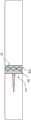
图1A示出了根据一些实施例的处于递送构造的阻塞系统的轮廓;Figure 1A shows an outline of an occlusion system in a delivery configuration in accordance with some embodiments;
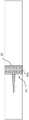
图1B示出了根据一些实施例的处于展开构造的阻塞系统的轮廓;FIG. 1B shows an outline of an occlusion system in a deployed configuration in accordance with some embodiments;
图2A-2C示出了根据一些实施例的锚定特征的各种示例;2A-2C illustrate various examples of anchoring features in accordance with some embodiments;
图3A-3B示出了根据一些实施例的阻隔构件的各种示例;3A-3B illustrate various examples of barrier members according to some embodiments;
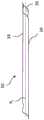
图4示出了根据一些实施例的自扩张阻塞系统的轮廓;4 shows an outline of a self-expanding occlusion system according to some embodiments;
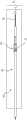
图5示出了根据一些实施例的具有未翻转的尾部部分的囊体可扩张阻塞系统的轮廓;5 illustrates an outline of a balloon-expandable occlusion system with an uninverted tail portion, according to some embodiments;
图6示出了根据一些实施例的具有翻转的尾部部分的囊体可扩张阻塞系统的轮廓;6 illustrates an outline of a balloon-expandable occlusion system with an inverted tail portion in accordance with some embodiments;
图7A-7D示出了根据一些实施例的将阻塞设备递送至患者的体腔的方法;7A-7D illustrate a method of delivering an occlusion device to a body cavity of a patient, according to some embodiments;
图8A-8D示出了根据一些实施例的将可植入阻塞设备递送至患者的体腔的另一种方法;8A-8D illustrate another method of delivering an implantable occlusion device to a body cavity of a patient in accordance with some embodiments;
图9是根据一些实施例的在患者的体腔内使用的阻塞设备的示例;9 is an example of an occlusion device for use within a body cavity of a patient, according to some embodiments;
图10是根据一些实施例的在患者的体腔内使用的阻塞设备的示例;10 is an example of an occlusion device for use within a body cavity of a patient, according to some embodiments;
图11A是根据一些实施例的在患者的体腔内使用的阻塞设备的示例;11A is an example of an occlusion device for use within a body cavity of a patient, according to some embodiments;
图11B是根据一些实施例的在患者的体腔内使用的阻塞设备的示例。11B is an example of an occlusion device for use within a body cavity of a patient, according to some embodiments.
本领域的技术人员将容易理解,本公开的各方面可通过构造成执行预期功能的任何数量的方法和装置来实现。还应注意的是,本文参考的附图不一定是按比例绘制,而有可能放大以说明本公开的各个方面,并且就此而言,附图不应理解为限制性的。Those skilled in the art will readily appreciate that aspects of the present disclosure may be implemented by any number of methods and apparatus configured to perform the intended functions. It should also be noted that the drawings referred to herein are not necessarily to scale, may be exaggerated to illustrate various aspects of the present disclosure, and are not to be considered limiting in this regard.
具体实施方式Detailed ways
本公开的各个方面涉及用于可植入医疗设备的设计,该可植入医疗设备用于阻塞诸如患者的脉管系统之类的体腔。可以根据期望将设备构造成用于部分阻塞(例如,限流)、选择性阻塞(例如,阀流(受控流动))和/或完全阻塞。如本文所使用的,术语“阻塞”包括部分阻塞、选择性阻塞和完全阻塞。此外,本公开的各个方面涉及用于在患者体内、比如患者的体腔之内的期望治疗位置处进行阻塞治疗的阻塞系统。作为参考,术语“体腔”应理解为包括患者体内任何能够阻塞的通道。在一些示例中,阻塞系统可包括递送导管和阻塞设备。阻塞设备可以是自扩张的、可以通过施加扩张力来扩张或通过其组合来扩张。Various aspects of the present disclosure relate to designs for implantable medical devices used to occlude body lumens such as a patient's vasculature. The device may be configured for partial occlusion (eg, flow restriction), selective occlusion (eg, valve flow (controlled flow)), and/or full occlusion, as desired. As used herein, the term "occlusion" includes partial occlusion, selective occlusion, and complete occlusion. Furthermore, various aspects of the present disclosure relate to occlusion systems for performing occlusion therapy at a desired treatment location within a patient's body, such as within a patient's body cavity. For reference, the term "body lumen" should be understood to include any passageway in a patient's body that can be blocked. In some examples, an occlusion system can include a delivery catheter and an occlusion device. The occlusion device can be self-expanding, can be expanded by application of an expansion force, or can be expanded by a combination thereof.
在某些情况下,例如在大流量或高流量血管通道中快速高效地密封体腔可能是有益的,以防止对该区域的进一步损害或对患者的不良影响。根据本文提供的示例,阻塞系统在多个方面都可能是有利的,包括使用高效制造工艺进行生产的能力,以及通过响应体腔内的自然体压(例如血压)来实现设备的闭合/密封来提供快速、安全和可靠的阻塞。In certain situations, such as in high-flow or high-flow vascular access, it may be beneficial to quickly and efficiently seal the body lumen to prevent further damage to the area or adverse effects on the patient. According to the examples provided herein, an occlusion system may be advantageous in a number of ways, including the ability to be produced using efficient manufacturing processes, and to provide rapid , safe and reliable blocking.
在一些示例中,本文所讨论的阻塞系统还可以利用单个设备来治疗各种各样的身体通道。在一些实例中,阻塞系统允许导丝穿过阻塞设备的两端,而不损害内腔密封,导致体液流入,或以其它方式干扰疗效。在一些示例中,该系统允许一根或多根导丝在设备递送期间、设备递送之后、和/或在从患者体内取出设备期间和之后将其保持在位,从而减少和/或消除了对多个设备和/或程序的需求。In some examples, the occlusion systems discussed herein may also utilize a single device to treat a wide variety of body passages. In some examples, the occlusion system allows the guidewire to pass through both ends of the occlusion device without compromising the lumen seal, causing the influx of bodily fluids, or otherwise interfering with therapeutic efficacy. In some examples, the system allows one or more guide wires to be held in place during device delivery, after device delivery, and/or during and after removal of the device from the patient, thereby reducing and/or eliminating the need for Requirements for multiple devices and/or programs.
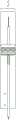
图1A示出了阻塞系统10,该阻塞系统10包括处于递送构造的递送导管12、阻塞设备14和可选的导丝16。递送导管12构造成用于将阻塞设备14递送至患者体内的期望位置。可采用系统10的身体通道的例子包括动脉、静脉、气道、胃肠道、泌尿道、胆道、左心耳、心脏壁、分流道和其它身体通道,无论是天然形成的还是人工形成的。FIG. 1A shows
如图1A所示,在一些实施例中,递送导管12具有近端18、远端20、中心纵向轴线XL、在近端18附近的近侧部分19以及在远端20附近的远侧部分21。递送导管12具有适合于到达患者体内的期望治疗位置的长度,以将设备14递送至期望治疗位置。例如,递送导管12可具有约80厘米至约140厘米的长度。然而,应当理解的是,根据包括期望治疗位置的多种因素,递送导管12可以具有任何期望的长度。尽管通常与阻塞系统10相关联地描述腔内递送方法,但是阻塞系统10还可在腹腔镜方法和其它手术方法中使用。递送导管12可包括常规医用级别的材料,诸如尼龙、聚丙烯酰胺、聚碳酸酯、聚乙烯、聚甲醛、聚丙烯酸甲酯、聚丙烯、聚四氟乙烯、聚三氟氯乙烯、聚氯乙烯、聚氨酯、弹性体有机硅聚合物,
如图1A所示,阻塞设备14包括阻隔构件30,该阻隔构件通常不渗透通过阻塞设备14的流体(对于该流体是不透的)。阻塞设备14还可包括能够将阻隔构件30保持在体腔内的附连元件40。在一些实施例中,阻隔构件30沿着中心纵向轴线XL定向并且包括长度L(图3A)。在各种示例中,阻隔构件30具有大致圆柱形的横截面结构,当阻塞设备14处于递送构造时,其具有内径D1和外径D2(图7A和7B)。阻隔构件30可以是管状套筒或护套的形式。在一些示例中,阻隔构件30固定于递送导管12、比如递送导管12的主体26。As shown in FIG. 1A , the
如上所述,附连元件40构造成在阻隔构件30从递送构造扩张至展开构造时保持阻隔构件30抵靠体腔的内壁60。在一些实施例中,附连元件40可以是锚定特征42,如图1B所示。As described above, the
图1B是处于扩张或展开构造的设备14的示例。如进一步描述的,设备14可在递送构造与展开构造之间扩张。例如,阻塞设备14可以是自扩张的、囊体可扩张的或其组合。如图所示,在展开之后,设备14包括可扩大部分22(在其它情况下称为接合部分,其具有内径D1’和外径D2’(未示出))以及密封部分或尾部部分24。如以下进一步详细描述的,尾部部分24具有中心内腔,该中心内腔构造成在身体压力下自密封。例如,如随后所讨论的,尾部部分24可选地由柔性或顺应性材料形成,并且构造成在尾部部分24之外的背压下塌缩。例如,附连元件40的上游侧上的流体压力将尾部部分24压缩成平坦或粉碎(破碎)的构造,从而密封阻隔构件30并防止流体从中流过。Figure IB is an example of
图2A-C示出了根据一些实施例的锚定特征的各种示例。在一些实施例中,如图2A所示,锚定构件42a可以是例如支承构件44。支承构件44包括在施加径向扩张力时可扩张的框架。例如,支承构件44可以是可扩张的支架环、自扩张支架或囊体可扩张支架等等。在一些实施例中,支承构件44可扩张至合适的尺寸和/或形状以在期望的治疗位置处装配在体腔内部。例如,支承构件44可在期望的治疗位置处具有近似等于体腔的内径的展开直径。支承构件44可由各种合适的且生物相容的材料形成,比如各种金属和非金属材料,包括形状记忆合金、镍钛合金、不锈钢、可膨胀聚合物、塑料以及其它生物相容的金属。2A-C illustrate various examples of anchoring features in accordance with some embodiments. In some embodiments, as shown in FIG. 2A ,
图2B示出了锚定特征的另一实施例。锚定特征42还可以是例如倒钩42b。如图2B所示,倒钩42b附连于体腔的内壁并且在期望的治疗位置处固定和/或密封阻隔构件30。例如,倒钩42b可以是捕获于(钩住)体腔的内壁以将阻隔构件30固定在期望的治疗位置处的钉状物、刺状物、钩状物或其它特征中的任何一个。Figure 2B shows another embodiment of an anchoring feature. The anchoring features 42 may also be
在另一示例中,如图2C所示,锚定特征42是粘性材料42c,比如围绕阻隔构件30的外壁的粘条或涂层。当阻隔构件30扩张时,粘性材料可以粘附至体腔的内壁,从而有助于在期望的治疗位置处将阻隔构件30固定和/或密封至周围的体腔。在其它实施例中,与尾部部分24相比,阻隔构件30的可扩大部分22可简单地包括更硬或更刚性的材料,使得可扩大部分22能够形成体腔的内壁。根据上述内容,应当理解的是,考虑了各种锚定特征42,并且还可实施上述示例的组合(例如,粘合剂、倒钩和/或支承构件组合)。In another example, as shown in FIG. 2C , the anchoring
图3A-B示出了根据一些实施例的阻隔构件的各种示例。在一些实施例中,阻隔构件30具有第一端32、第二端34、在第一端32附近的第一部分33、在第二端34附近的第二部分35以及沿着中心纵向轴线XL从第一端32延伸至第二端34的内腔36。在一些实施例中,阻隔构件30构造成连续的、管状的或圆柱形的形状,如图3A所示。例如,阻隔构件30可被挤出、裹绕或以其它方式形成为连续管。在一些实施例中,阻隔构件30可包括促进尾部部分24塌缩或变平的特征。此类特征可主要包括例如褶皱、折叠部、接缝、穿孔和激光切割线等。在一些示例中,阻隔构件30可包括如图3B所示的一个或多个材料层或材料片(例如,薄膜材料)。例如,阻隔构件30可以包括第一片38,该第一片38粘附于第二片39以形成一对纵向接缝和内腔36。在其它示例中,阻隔构件30的尾部部分24可包括相对的纵向褶皱,以有助于塌缩。如以下更详细地描述的那样,这种设置在压力下具有较低的抗塌缩能力(例如,与圆形横截面相比),并且可促进更有效的密封。3A-B illustrate various examples of barrier members according to some embodiments. In some embodiments, the
在一些示例中,阻隔构件30的长度L可为约5厘米至约20厘米。然而,该长度可取决于多种因素而变化,包括患者的解剖结构和期望的治疗位置。阻隔构件30可具有合适的外径D2,使得外径D2与长度L之比为至少1比10。In some examples, the length L of the
在一示例中,阻隔构件30是弹性的并且构造成拉伸。阻隔构件30可以包括任何合适的可扩张的且生物相容的材料。合适材料的示例包括例如含氟聚合物(例如,聚四氟乙烯)、聚氨酯、聚醚嵌段酰胺和诸如聚硅氧烷之类的各种弹性体有机硅聚合物。在各种示例中,阻隔构件30包括由聚四氟乙烯、聚乙烯或根据期望的其它材料形成的颈缩膜。如本文所述,术语“颈缩膜”可以定义为由于局部应变而能够纵向变形并减小横截面面积的材料的膜或层。In one example, the
图4示出了根据一些实施例的自扩张阻塞系统的轮廓。在一些实施例中,阻塞系统10还可包括约束件70,在其它情况下其被称为护套或套筒,该约束件70构造成在期望展开之前防止设备14自扩张。如图所示,阻隔构件30可在第一部分33和/或第一端32处可移除地联接于递送导管12(例如,主体26)。在一些实施例中,阻隔构件30的至少第一部分33和/或第一端32可从递送构造扩张至展开构造。4 shows an outline of a self-expanding occlusion system according to some embodiments. In some embodiments, the
图5示出了根据一些实施例的囊体可扩张阻塞系统的轮廓。如图所示,囊体80可操作地联接于递送导管12的主体26,使得能够将囊体80的直径调节至扩大的直径。在一些示例中,设备14可移除地联接于囊体80并且构造成在囊体80膨胀时扩张。5 shows an outline of a balloon-expandable occlusion system in accordance with some embodiments. As shown,
根据期望,囊体80可位于沿着导管12的主体26的各种位置中的任何位置处,通常包括在导管12的近端18与远端20之间的任何点。在一些实施例中,如图5所示,阻隔构件30在其第一部分33或第一端32处可移除地联接于囊体80。根据期望,阻隔构件30可在沿着囊体80的工作长度的任何位置处联接于囊体80。The
囊体80可以包括是大致无弹性的材料,并允许囊体80在足够的压力(加压)下扩张至期望的直径。囊体80可以由多种合适的生物相容的材料中的任何一种形成。例如,合适的材料可包括尼龙、聚乙烯、聚对苯二甲酸乙二醇酯(PET)、聚己内酰胺、聚酯、聚醚、聚酰胺、聚氨酯、聚酰亚胺、丙烯腈丁二烯苯乙烯(ABS)共聚物、聚酯/聚醚嵌段共聚物、离聚物树脂、液晶聚合物、刚性杆聚合物、聚氨酯、乳胶和诸如聚硅氧烷之类的弹性有机硅聚合物。
如图6所示,在一些示例中,阻隔构件30的至少一部分重叠在其自身上(例如,在翻转过程期间)。例如,阻隔构件30的尾部部分24可选地翻转以限定重叠部分25和翻转的材料段(材料的翻转长度)。如图所示,阻隔构件30的第一端32和第二端34均沿相同方向(例如,朝向递送导管12的远端20)定向。在一些实施例中,重叠部分25可以比尾部部分24短。尾部部分24可具有约7厘米至约25厘米或约10厘米至约21厘米的长度。然而,尾部部分24可具有期望的任何长度,该长度可取决于期望的治疗位置。As shown in FIG. 6, in some examples, at least a portion of the
在一些实施例中,阻隔构件30的第一端32或尾部部分24可选地在递送导管12的远端20附近联接于或粘附于递送导管12的主体26,从而当从患者体内移除递送导管12时允许第一端32向近侧缩回。在一些实施例中,第一端32或尾部部分24借助于粘性材料(例如,阻隔构件30的内腔36的内壁上的粘条)粘附于递送导管12。然而,第一端32或尾部部分24能够以各种其它方式联接于递送导管12,比如例如摩擦配合、热结合、锚定件、紧固件或根据期望的其它类型的附连。In some embodiments, the
在一些实施例中,阻隔构件30的第一端32或尾部24构造成在阻隔构件30的可扩大部分22扩张之后通过向导管施加张力或缩回力而从递送导管12脱离。例如,当递送导管12从患者体内缩回时,尾部部分24可从递送导管12脱离。在一些实施例中,阻隔构件30的尾部部分24构造成在从递送导管12脱离期间直径颈缩或减小。例如,尾部部分24可在从递送导管12脱离的过程中弹性地恢复减小的直径、或者拉伸或伸长以塑性变形为较小的直径,从而在第一端32处产生比在第二端34处更小的直径。In some embodiments, the
在各种示例中,阻隔构件30的尾部部分24不受径向支承并且构造成在压力下塌缩到自身上并闭合。尾部部分24可在外部压力下抵靠自身变平或压缩以形成密封部。在一些实施例中,阻隔构件30由于体腔内的流体压力(例如,血压)而变平或压缩。例如,当展开时,在设备14的第一侧上并且在阻隔构件30外部的流体压力,并且特别是阻隔构件30的尾部部分24上的流体压力可高于在设备的第二侧上并且在阻隔构件30内的流体压力,从而使阻隔构件30的尾部部分24抵靠自身变平或压缩。In various examples, the
在一些实施例中,尾部部分24可纵向塌缩(例如,通过“收缩(蜷缩)”)。在一些实施例中,尾部部分24可沿直径方向塌陷,比如当为管状时(例如,图3A)。在一些实施例中,阻隔构件30可通过变平而径向塌缩。例如,当形成有在相对的接缝处固定在一起的两个相对的侧部或片(例如,图3B)时,第一片39和第二片41可容易地抵靠彼此变平以封闭(闭合)内腔36。如上所述,阻隔构件30可弄皱、刻痕、打褶、折叠、形成接缝或以其它方式处理以促进在压力下的可重复塌缩。In some embodiments, the
图7A-D示出了将阻塞设备14递送至期望的治疗区域的方法。尽管本文讨论的方法包括囊体可扩张系统,但是该方法也可以用于自扩张系统或其它系统。7A-D illustrate a method of delivering the
如图7A所示,阻塞系统10引入患者体内,并沿着导丝16引导至体腔62内的期望治疗区域。如上所述,期望的治疗区域可以是静脉、动脉、胃肠道或其他身体通道中的任何一个。体腔62包括具有内径DL的内壁60。As shown in FIG. 7A , the
一旦处于期望的治疗位置处,阻隔构件30的至少可扩大部分22就从递送构造(图7A)扩张至展开构造(图7B)。如图所示,阻隔构件30和/或锚定特征42经由囊体80的膨胀而扩张。然而,如上所述,阻隔构件30和/或锚定特征42还可在移除约束件70(图4)后自扩张。Once at the desired treatment site, at least the
当处于展开构造时,阻隔构件30和锚定特征42具有大约等于体腔62的内径DL的展开直径。在锚定特征42是支承构件44的一些实施例中,支承构件44与体腔62的内壁60形成压力配合,并且保持阻隔构件30抵靠内壁60。尽管示出为与支承构件44一起使用,但是系统10可以使用如上所述的各种锚定特征42。例如,阻隔构件30可以经由倒钩(图2B)和/或诸如粘性材料(图2C)之类的其它锚定机构保持或附连于内壁60。When in the deployed configuration, the
然后,递送导管12沿箭头A所示的方向从体腔62向近侧缩回。在一些实施例中,第二端34被牵拉穿过阻隔构件30的可扩大部分22,并形成沿近侧方向定向的尾部部分24(图7C)。例如,阻隔构件30可选地通过重叠部分25和支承构件44翻转回来(反过来翻转通过重叠部分25和支承构件44),以形成尾部部分24。在一些实施例中,随着递送导管12缩回,尾部部分24被拉伸并且直径颈缩或减小。在其它实施例中,当支承构件44从递送构造扩张至展开构造时,尾部部分24可使直径颈缩或减小。在其它实施例中,尾部部分24抵靠自身变平或压缩以形成密封部,如上所述。当将递送导管12从体腔62移除时,阻隔构件30的第二端34或尾部部分24从递送导管12脱离(例如,经由变形尾部部分24与递送导管12之间的剪切作用),其中阻隔构件30的第二端34随后闭合以形成密封部。The
如图7C所示,尾部部分24沿流体流动穿过体腔62(即,在支承构件44的上游)的相反方向(由箭头B表示)定向。如上所述,支承构件44的上游侧上的流体压力将尾部部分24压缩成如图7D所示的平坦或粉碎的构造,从而密封阻隔构件30,防止流体从中流过并且阻塞了体腔62。As shown in Figure 7C, the
图8A-D示出了另一实施例,其中阻隔构件30不作为组装至递送导管12的一部分而翻转。如图所示,阻隔构件30类似地展开,但不是经由递送导管12的缩回而使阻隔构件30翻转以形成尾部部分24,而是尾部24仅被拉动、颈缩并从递送导管12释放,之后尾部部分24被血压压缩并自密封。FIGS. 8A-D illustrate another embodiment in which the
图8A示出了阻塞系统10,该阻塞系统10引入患者体内,并沿着导丝16引导至体腔62内的期望治疗区域。如上所述,期望的治疗区域可以是静脉、动脉、胃肠道或其他身体通道中的任何一个。FIG. 8A shows the
一旦处于期望的治疗位置处,阻隔构件30的至少可扩大部分22就从递送构造(图8A)扩张至展开构造(图8B)。如图所示,阻隔构件30和/或锚定特征42经由囊体80的膨胀而扩张。然而,如上所述,阻隔构件30和/或锚定特征42还可在移除约束件70后自扩张。Once at the desired treatment location, at least the
然后,递送导管12沿箭头A所示的方向从体腔62向近侧缩回。在一些实施例中,第二端34保持沿近侧方向(图8C)。然后,当递送导管12通过阻隔构件30缩回时,尾部部分24可被拉伸并使直径颈缩或减小。在其它实施例中,当支承构件44从递送构造扩张至展开构造时,尾部部分24可使直径颈缩或减小。在其它实施例中,尾部部分24抵靠自身变平或压缩以形成密封部,如上所述。The
如图8C所示,尾部部分24沿流体流动穿过体腔62(即,在支承构件44的上游)的相反方向(由箭头B表示)定向。如上所述,支承构件44的上游侧上的流体压力将尾部部分24压缩成如图8D所示的平坦或粉碎的构造,从而密封阻隔构件30,防止流体从中流过并且阻塞了体腔62。As shown in FIG. 8C , the
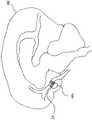
如上所详细描述的,图9-11B示出了在各种期望的治疗位置处展开的阻塞设备。例如,图9示出了根据一实施例的在患者的体腔内使用的阻塞设备14。在这样的示例中,设备14用于阻塞患者的心脏H与下腔静脉IVC之间的孔、开窗部或通道(例如,在Fontan程序中)。As described in detail above, Figures 9-11B illustrate the occlusion device deployed at various desired treatment locations. For example, Figure 9 illustrates an
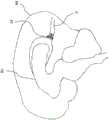
在另一示例中,如图10所示,设备14可以用于阻塞大脑BR中的各种通道,以例如旁通或阻塞动脉瘤AN。In another example, as shown in Figure 10, the
在另一示例中,如图11A所示,设备14可以用作可选的单向阀。例如,设备14可放置在尿路UT(患者膀胱BL的下游)中,以减轻和/或减少某些病症的严重性,比如例如尿失禁。如果流体压力在设备14的上游侧下降,则尾部部分24(定向在设备14的上游侧)可塌缩到自身上并形成密封部。In another example, as shown in FIG. 11A,
在另一示例中,如图11B所示,设备14可以用作用于治疗诸如脑积水之类的病症的单向卸压阀,在脑积水中脑脊液积聚并且必须偶尔被缓解。在这样的示例中,如果在设备14的上游侧上的流体压力超过在设备14的下游侧上的或在设备14的尾部部分24所定向的一侧上的流体压力,则设备14可允许流体沿一个方向流动(即,在脑积水的情况下,从脑室(BV)进入静脉系统(V))。如果设备14的下游侧上的流体压力超过上游侧上的压力,则尾部部分24可塌缩到自身上并形成密封部。In another example, as shown in Figure 1 IB, the
以下示例说明了与先前的描述一致的各种设计的性能。这些示例应以说明性方式阅读,而不应被理解为限制本公开的范围。The following examples illustrate the performance of various designs consistent with the previous description. These examples should be read in an illustrative fashion and should not be construed as limiting the scope of the present disclosure.
示例Example
以下示例说明了直径可变的阻隔构件的反转的尾部长度与泄漏量之间的关系。在所有示例中使用的阻隔构件的起始长度为8英寸。阻隔构件由ePTFE膜组成,该ePTFE膜能够在翻转时从起始直径拉伸和/或颈缩至较小的颈缩直径。在翻转后,阻隔构件放置在塑料圆筒内,并在圆筒中填充水至模拟人体血压的压力。在每次样品运行后,将阻隔构件切短。例如,在第一次样品运行后,将阻隔构件从8英寸切成6英寸。因此,对于每个样品使用相同的阻隔构件。The following example illustrates the relationship between the reversed tail length and leakage of a variable diameter barrier member. The starting length of the barrier members used in all examples was 8 inches. The barrier member consists of an ePTFE membrane that can be stretched and/or necked from an initial diameter to a smaller necked diameter upon inversion. After inversion, the barrier member is placed inside a plastic cylinder, and the cylinder is filled with water to a pressure that simulates human blood pressure. The barrier members were cut short after each sample run. For example, after the first sample run, the barrier member was cut from 8 inches to 6 inches. Therefore, the same barrier member was used for each sample.
示例1Example 1
对于原始直径为0.050英寸(0.127厘米)的阻隔构件,观察到翻转尾部长度对泄漏的影响。下表1中列出了每种样品的各种水压和相应的翻转尾部长度。The effect of overturned tail length on leakage was observed for the barrier member with an original diameter of 0.050 inches (0.127 cm). The various water pressures and corresponding flip tail lengths for each sample are listed in Table 1 below.
表1.Table 1.

如表1所示,翻转尾部长度分别为8英寸(20.32厘米)和6英寸(15.24厘米)的样品1和2,当经受与血压相似的水压时,没有可见的泄漏迹象。翻转尾部长度为4英寸(10.16厘米)的样品3表现出微量泄漏。而翻转尾部长度分别为3英寸(7.62厘米)和2英寸(5.08厘米)的样品4和5,表现出缓慢至中度的泄漏。因此,得出的结论是,较短的翻转尾部长度(特别是小于4英寸(7.62厘米)的尾部长度)比较长的翻转尾部表现出更大的泄漏量。As shown in Table 1, Samples 1 and 2, with tail lengths of 8 inches (20.32 centimeters) and 6 inches (15.24 centimeters), respectively, had no visible signs of leakage when subjected to water pressures similar to blood pressure. Sample 3, which had a 4 inch (10.16 cm) flip tail length, exhibited trace leakage. In contrast, Samples 4 and 5, with flip tail lengths of 3 inches (7.62 cm) and 2 inches (5.08 cm), respectively, exhibited slow to moderate leakage. Therefore, it was concluded that shorter flipped tail lengths (especially those less than 4 inches (7.62 cm)) exhibited greater leakage than longer flipped tails.
示例2Example 2
对于直径为0.100英寸(0.254厘米)的阻隔构件,观察到翻转尾部长度对泄漏的影响。下表2中列出了每种样品的各种水压和相应的翻转尾部长度。The effect of overturned tail length on leakage was observed for a 0.100 inch (0.254 cm) diameter barrier member. The various water pressures and corresponding flip tail lengths for each sample are listed in Table 2 below.
表2.Table 2.

如表2所示,具有6英寸(15.24cm)的翻转尾部长度的样品6的泄漏速度比具有4英寸(7.62cm)和2英寸(5.08cm)的翻转尾部长度的样品7和8的泄漏慢。因此,如实验1总结的,通常,较长的翻转尾部长度与较少和/或较慢的泄漏有关,而较短的翻转尾部长度与更多和/或较快的泄漏有关。As shown in Table 2, Sample 6 with an inverted tail length of 6 inches (15.24 cm) leaked slower than Samples 7 and 8 with inverted tail lengths of 4 inches (7.62 cm) and 2 inches (5.08 cm). . Thus, as summarized in Experiment 1, in general, longer flip tail lengths are associated with less and/or slower leakage, while shorter flip tail lengths are associated with more and/or faster leakage.
当比较示例1和2时,得出的结论是较小直径的管相比具有相同翻转尾部长度的较大直径的管表现出较少的泄漏。例如,直径为0.050英寸(0.127厘米)、尾部长度为6英寸(15.24厘米)的样品2的泄漏量少于具有相同的尾部长度但直径为0.100英寸(0.254厘米)的样品6。类似地,示例3和7具有相同的尾部长度(4英寸),但是示例3仅表现出微量泄漏,而实施例7表现出中度泄漏。When comparing Examples 1 and 2, it was concluded that the smaller diameter tube exhibited less leakage than the larger diameter tube with the same flip tail length. For example, Sample 2 with a diameter of 0.050 inches (0.127 cm) and a tail length of 6 inches (15.24 cm) leaked less than Sample 6 with the same tail length but a diameter of 0.100 inches (0.254 cm). Similarly, Examples 3 and 7 had the same tail length (4 inches), but Example 3 exhibited only minor leakage, while Example 7 exhibited moderate leakage.
如上所述,示例1和2是在塑料瓶中用水模拟血压进行的。由于血液和其它体液通常比水粘稠,因此预计翻转尾部的泄漏量比以上示例1和2观察到的更少和/或更慢。因此,预期没有观察到泄漏或仅发现微量泄漏的样品最终将会在人体中被阻塞。As mentioned above, Examples 1 and 2 were performed with water in a plastic bottle to simulate blood pressure. Since blood and other bodily fluids are generally more viscous than water, leakage from the flipped tail is expected to be less and/or slower than that observed in Examples 1 and 2 above. Therefore, it is expected that samples in which no leakage or only a small amount of leakage is observed will eventually be blocked in humans.
上文已经一般性地并且关于具体实施例描述了本申请的发明。对于本领域技术人员将显而易见的是,在不脱离本公开的范围的情况下,可以对各实施例进行各种修改和变化。因此,旨在使各实施例覆盖本发明的修改和变型,只要它们落入所附权利要求及其等同物的范围内即可。The invention of the present application has been described above generally and with respect to specific embodiments. It will be apparent to those skilled in the art that various modifications and variations can be made in the various embodiments without departing from the scope of the present disclosure. Therefore, it is intended that the embodiments cover modifications and variations of the present invention provided they fall within the scope of the appended claims and their equivalents.
Claims (20)
Applications Claiming Priority (3)
| Application Number | Priority Date | Filing Date | Title |
|---|---|---|---|
| US201862668505P | 2018-05-08 | 2018-05-08 | |
| US62/668,505 | 2018-05-08 | ||
| PCT/US2019/028744WO2019217069A1 (en) | 2018-05-08 | 2019-04-23 | Occluder devices |
Publications (2)
| Publication Number | Publication Date |
|---|---|
| CN112087972Atrue CN112087972A (en) | 2020-12-15 |
| CN112087972B CN112087972B (en) | 2024-10-29 |
Family
ID=66655433
Family Applications (1)
| Application Number | Title | Priority Date | Filing Date |
|---|---|---|---|
| CN201980030939.3AActiveCN112087972B (en) | 2018-05-08 | 2019-04-23 | Occlusion device |
Country Status (7)
| Country | Link |
|---|---|
| US (2) | US11564693B2 (en) |
| EP (1) | EP3790474A1 (en) |
| JP (1) | JP2021523770A (en) |
| CN (1) | CN112087972B (en) |
| AU (2) | AU2019266086A1 (en) |
| CA (1) | CA3096485C (en) |
| WO (1) | WO2019217069A1 (en) |
Families Citing this family (2)
| Publication number | Priority date | Publication date | Assignee | Title |
|---|---|---|---|---|
| US11564693B2 (en) | 2018-05-08 | 2023-01-31 | W. L. Gore & Associates, Inc. | Occluder devices |
| WO2021195085A1 (en)* | 2020-03-24 | 2021-09-30 | Boston Scientific Scimed, Inc. | Medical system for treating a left atrial appendage |
Citations (12)
| Publication number | Priority date | Publication date | Assignee | Title |
|---|---|---|---|---|
| CN1216929A (en)* | 1996-02-02 | 1999-05-19 | 血管转换公司 | Method and apparatus for blocking flow through blood vessels |
| US20020022860A1 (en)* | 2000-08-18 | 2002-02-21 | Borillo Thomas E. | Expandable implant devices for filtering blood flow from atrial appendages |
| WO2003077984A1 (en)* | 2002-03-15 | 2003-09-25 | Transvascular, Inc. | Implantable lumen occluding devices and methods |
| US20040093070A1 (en)* | 2002-05-10 | 2004-05-13 | Hikmat Hojeibane | Frame based unidirectional flow prosthetic implant |
| WO2005011535A2 (en)* | 2003-07-31 | 2005-02-10 | Cook Incorporated | Prosthetic valve for implantation in a body vessel |
| US20120130468A1 (en)* | 2010-07-27 | 2012-05-24 | Fred Khosravi | Methods and apparatus for treating neurovascular venous outflow obstruction |
| CN102791223A (en)* | 2010-03-05 | 2012-11-21 | 爱德华兹生命科学公司 | Low-profile heart valve and delivery system |
| CN102811672A (en)* | 2009-11-03 | 2012-12-05 | 大口径封闭有限责任公司 | Closure Device |
| US20140031924A1 (en)* | 2012-07-25 | 2014-01-30 | W. L. Gore & Associates, Inc. | Everting transcatheter valve and methods |
| CN104053409A (en)* | 2012-01-13 | 2014-09-17 | W.L.戈尔及同仁股份有限公司 | Implantable shape-memory occlusion devices and methods of their manufacture and use |
| US20140364941A1 (en)* | 2009-06-17 | 2014-12-11 | Coherex Medical, Inc. | Medical device for modification of left atrial appendage and related systems and methods |
| CN105899150A (en)* | 2013-07-31 | 2016-08-24 | Emba医疗有限公司 | Methods and devices for endovascular embolization |
Family Cites Families (25)
| Publication number | Priority date | Publication date | Assignee | Title |
|---|---|---|---|---|
| US5382261A (en) | 1992-09-01 | 1995-01-17 | Expandable Grafts Partnership | Method and apparatus for occluding vessels |
| US20030229366A1 (en) | 1996-02-02 | 2003-12-11 | Transvascular, Inc. | Implantable lumen occluding devices and methods |
| US6254633B1 (en)* | 1997-02-12 | 2001-07-03 | Corvita Corporation | Delivery device for a medical device having a constricted region |
| US5941896A (en)* | 1997-09-08 | 1999-08-24 | Montefiore Hospital And Medical Center | Filter and method for trapping emboli during endovascular procedures |
| US6468291B2 (en)* | 1999-07-16 | 2002-10-22 | Baff Llc | Emboli filtration system having integral strut arrangement and methods of use |
| US6589263B1 (en)* | 1999-07-30 | 2003-07-08 | Incept Llc | Vascular device having one or more articulation regions and methods of use |
| US6702834B1 (en)* | 1999-12-30 | 2004-03-09 | Advanced Cardiovascular Systems, Inc. | Embolic protection devices |
| US8298257B2 (en)* | 2000-06-29 | 2012-10-30 | Concentric Medical, Inc. | Systems, methods and devices for removing obstructions from a blood vessel |
| US20060265052A1 (en)* | 2001-03-29 | 2006-11-23 | Isis Innovation Limited | Deployable stent |
| US6755847B2 (en)* | 2001-10-05 | 2004-06-29 | Scimed Life Systems, Inc. | Emboli capturing device and method of manufacture therefor |
| US6817927B2 (en) | 2001-10-19 | 2004-11-16 | Eastman Kodak Company | Method of removing material from an external surface using core/shell particles |
| DE60315425T2 (en)* | 2002-03-05 | 2008-06-26 | Salviac Ltd. | SYSTEM FOR PROTECTION FROM EMBOLICS |
| US20040093012A1 (en)* | 2002-10-17 | 2004-05-13 | Cully Edward H. | Embolic filter frame having looped support strut elements |
| US7604650B2 (en)* | 2003-10-06 | 2009-10-20 | 3F Therapeutics, Inc. | Method and assembly for distal embolic protection |
| US20120041550A1 (en)* | 2003-12-23 | 2012-02-16 | Sadra Medical, Inc. | Methods and Apparatus for Endovascular Heart Valve Replacement Comprising Tissue Grasping Elements |
| US8945169B2 (en)* | 2005-03-15 | 2015-02-03 | Cook Medical Technologies Llc | Embolic protection device |
| JP4912395B2 (en)* | 2005-05-24 | 2012-04-11 | エドワーズ ライフサイエンシーズ コーポレイション | Rapid placement prosthetic heart valve |
| US8187298B2 (en)* | 2005-08-04 | 2012-05-29 | Cook Medical Technologies Llc | Embolic protection device having inflatable frame |
| US9232992B2 (en) | 2008-07-24 | 2016-01-12 | Aga Medical Corporation | Multi-layered medical device for treating a target site and associated method |
| GB201018869D0 (en)* | 2010-11-08 | 2010-12-22 | Isis Innovation | Curved stent graft assembly |
| US8948848B2 (en)* | 2011-01-07 | 2015-02-03 | Innovative Cardiovascular Solutions, Llc | Angiography catheter |
| US20140005540A1 (en)* | 2011-01-07 | 2014-01-02 | Innovative Cardiovascular Solutions, Inc. | Angiography Catheter |
| US9265512B2 (en)* | 2013-12-23 | 2016-02-23 | Silk Road Medical, Inc. | Transcarotid neurovascular catheter |
| US10441258B2 (en)* | 2017-06-16 | 2019-10-15 | Cardia, Inc. | Uncoupled LAA device |
| US11564693B2 (en) | 2018-05-08 | 2023-01-31 | W. L. Gore & Associates, Inc. | Occluder devices |
- 2019
- 2019-04-23USUS17/053,421patent/US11564693B2/enactiveActive
- 2019-04-23CACA3096485Apatent/CA3096485C/enactiveActive
- 2019-04-23JPJP2020561909Apatent/JP2021523770A/enactivePending
- 2019-04-23WOPCT/US2019/028744patent/WO2019217069A1/ennot_activeCeased
- 2019-04-23CNCN201980030939.3Apatent/CN112087972B/enactiveActive
- 2019-04-23AUAU2019266086Apatent/AU2019266086A1/ennot_activeAbandoned
- 2019-04-23EPEP19726797.4Apatent/EP3790474A1/enactivePending
- 2022
- 2022-02-25AUAU2022201337Apatent/AU2022201337B2/enactiveActive
- 2022-12-23USUS18/088,183patent/US12171436B2/enactiveActive
Patent Citations (13)
| Publication number | Priority date | Publication date | Assignee | Title |
|---|---|---|---|---|
| CN1216929A (en)* | 1996-02-02 | 1999-05-19 | 血管转换公司 | Method and apparatus for blocking flow through blood vessels |
| US20020022860A1 (en)* | 2000-08-18 | 2002-02-21 | Borillo Thomas E. | Expandable implant devices for filtering blood flow from atrial appendages |
| WO2003077984A1 (en)* | 2002-03-15 | 2003-09-25 | Transvascular, Inc. | Implantable lumen occluding devices and methods |
| US20040093070A1 (en)* | 2002-05-10 | 2004-05-13 | Hikmat Hojeibane | Frame based unidirectional flow prosthetic implant |
| WO2005011535A2 (en)* | 2003-07-31 | 2005-02-10 | Cook Incorporated | Prosthetic valve for implantation in a body vessel |
| US20050085900A1 (en)* | 2003-07-31 | 2005-04-21 | Case Brian C. | Prosthetic valve for implantation in a body vessel |
| US20140364941A1 (en)* | 2009-06-17 | 2014-12-11 | Coherex Medical, Inc. | Medical device for modification of left atrial appendage and related systems and methods |
| CN102811672A (en)* | 2009-11-03 | 2012-12-05 | 大口径封闭有限责任公司 | Closure Device |
| CN102791223A (en)* | 2010-03-05 | 2012-11-21 | 爱德华兹生命科学公司 | Low-profile heart valve and delivery system |
| US20120130468A1 (en)* | 2010-07-27 | 2012-05-24 | Fred Khosravi | Methods and apparatus for treating neurovascular venous outflow obstruction |
| CN104053409A (en)* | 2012-01-13 | 2014-09-17 | W.L.戈尔及同仁股份有限公司 | Implantable shape-memory occlusion devices and methods of their manufacture and use |
| US20140031924A1 (en)* | 2012-07-25 | 2014-01-30 | W. L. Gore & Associates, Inc. | Everting transcatheter valve and methods |
| CN105899150A (en)* | 2013-07-31 | 2016-08-24 | Emba医疗有限公司 | Methods and devices for endovascular embolization |
Also Published As
| Publication number | Publication date |
|---|---|
| CA3096485C (en) | 2023-02-28 |
| EP3790474A1 (en) | 2021-03-17 |
| US11564693B2 (en) | 2023-01-31 |
| US20210228216A1 (en) | 2021-07-29 |
| CN112087972B (en) | 2024-10-29 |
| AU2022201337B2 (en) | 2023-08-03 |
| US12171436B2 (en) | 2024-12-24 |
| CA3096485A1 (en) | 2019-11-14 |
| US20230131277A1 (en) | 2023-04-27 |
| AU2022201337A1 (en) | 2022-03-24 |
| WO2019217069A1 (en) | 2019-11-14 |
| JP2021523770A (en) | 2021-09-09 |
| AU2019266086A1 (en) | 2020-11-05 |
Similar Documents
| Publication | Publication Date | Title |
|---|---|---|
| US7744652B2 (en) | Aneurysm sealing device | |
| US9247942B2 (en) | Reversible tubal contraceptive device | |
| US12171436B2 (en) | Occluder devices | |
| CA2774279A1 (en) | Vasculature closure devices and methods | |
| US12376977B2 (en) | Stent graft device with anchoring members having adjustable geometries | |
| US9872788B2 (en) | Device for protecting hemorrhoids | |
| WO2014200563A1 (en) | Catheter-assisted tumor treatment | |
| GB2516423A (en) | Vascular closure device | |
| US20160089255A1 (en) | Removable vascular occlusion device | |
| JP2000279533A (en) | Stent for blood vessel knob shaping blood vessel and apparatus for treating blood vessel knob shaping blood vessel | |
| JP2010142634A (en) | Aneurysm blocker | |
| JP2015524311A (en) | Blood loss control system | |
| CA3003629C (en) | Occluder and anastomosis devices | |
| AU2013205292B2 (en) | Reversible tubal contraceptive device |
Legal Events
| Date | Code | Title | Description |
|---|---|---|---|
| PB01 | Publication | ||
| PB01 | Publication | ||
| SE01 | Entry into force of request for substantive examination | ||
| SE01 | Entry into force of request for substantive examination | ||
| GR01 | Patent grant | ||
| GR01 | Patent grant |