CN112087550A - Display method and image generation device - Google Patents
Display method and image generation deviceDownload PDFInfo
- Publication number
- CN112087550A CN112087550ACN202010509804.XACN202010509804ACN112087550ACN 112087550 ACN112087550 ACN 112087550ACN 202010509804 ACN202010509804 ACN 202010509804ACN 112087550 ACN112087550 ACN 112087550A
- Authority
- CN
- China
- Prior art keywords
- virtual space
- image
- area
- control unit
- display
- Prior art date
- Legal status (The legal status is an assumption and is not a legal conclusion. Google has not performed a legal analysis and makes no representation as to the accuracy of the status listed.)
- Pending
Links
Images


Classifications
- G—PHYSICS
- G06—COMPUTING OR CALCULATING; COUNTING
- G06T—IMAGE DATA PROCESSING OR GENERATION, IN GENERAL
- G06T19/00—Manipulating 3D models or images for computer graphics
- G06T19/006—Mixed reality
- H—ELECTRICITY
- H04—ELECTRIC COMMUNICATION TECHNIQUE
- H04N—PICTORIAL COMMUNICATION, e.g. TELEVISION
- H04N1/00—Scanning, transmission or reproduction of documents or the like, e.g. facsimile transmission; Details thereof
- H04N1/00795—Reading arrangements
- H04N1/00827—Arrangements for reading an image from an unusual original, e.g. 3-dimensional objects
- G—PHYSICS
- G06—COMPUTING OR CALCULATING; COUNTING
- G06F—ELECTRIC DIGITAL DATA PROCESSING
- G06F3/00—Input arrangements for transferring data to be processed into a form capable of being handled by the computer; Output arrangements for transferring data from processing unit to output unit, e.g. interface arrangements
- G06F3/01—Input arrangements or combined input and output arrangements for interaction between user and computer
- G06F3/011—Arrangements for interaction with the human body, e.g. for user immersion in virtual reality
- G—PHYSICS
- G06—COMPUTING OR CALCULATING; COUNTING
- G06T—IMAGE DATA PROCESSING OR GENERATION, IN GENERAL
- G06T17/00—Three dimensional [3D] modelling, e.g. data description of 3D objects
- G—PHYSICS
- G06—COMPUTING OR CALCULATING; COUNTING
- G06T—IMAGE DATA PROCESSING OR GENERATION, IN GENERAL
- G06T17/00—Three dimensional [3D] modelling, e.g. data description of 3D objects
- G06T17/10—Constructive solid geometry [CSG] using solid primitives, e.g. cylinders, cubes
- G—PHYSICS
- G06—COMPUTING OR CALCULATING; COUNTING
- G06T—IMAGE DATA PROCESSING OR GENERATION, IN GENERAL
- G06T7/00—Image analysis
- G06T7/50—Depth or shape recovery
- G—PHYSICS
- G06—COMPUTING OR CALCULATING; COUNTING
- G06T—IMAGE DATA PROCESSING OR GENERATION, IN GENERAL
- G06T7/00—Image analysis
- G06T7/90—Determination of colour characteristics
- G—PHYSICS
- G06—COMPUTING OR CALCULATING; COUNTING
- G06T—IMAGE DATA PROCESSING OR GENERATION, IN GENERAL
- G06T2200/00—Indexing scheme for image data processing or generation, in general
- G06T2200/24—Indexing scheme for image data processing or generation, in general involving graphical user interfaces [GUIs]
- G—PHYSICS
- G06—COMPUTING OR CALCULATING; COUNTING
- G06T—IMAGE DATA PROCESSING OR GENERATION, IN GENERAL
- G06T2207/00—Indexing scheme for image analysis or image enhancement
- G06T2207/10—Image acquisition modality
- G06T2207/10028—Range image; Depth image; 3D point clouds
- G—PHYSICS
- G06—COMPUTING OR CALCULATING; COUNTING
- G06T—IMAGE DATA PROCESSING OR GENERATION, IN GENERAL
- G06T2210/00—Indexing scheme for image generation or computer graphics
- G06T2210/56—Particle system, point based geometry or rendering
Landscapes
- Engineering & Computer Science (AREA)
- Physics & Mathematics (AREA)
- Theoretical Computer Science (AREA)
- General Physics & Mathematics (AREA)
- Software Systems (AREA)
- Computer Graphics (AREA)
- General Engineering & Computer Science (AREA)
- Geometry (AREA)
- Computer Vision & Pattern Recognition (AREA)
- Computer Hardware Design (AREA)
- Signal Processing (AREA)
- Multimedia (AREA)
- Human Computer Interaction (AREA)
- Processing Or Creating Images (AREA)
- User Interface Of Digital Computer (AREA)
Abstract
Translated fromChinese
Description
Translated fromChinese技术领域technical field
本发明涉及显示方法以及图像生成装置。The present invention relates to a display method and an image generation device.
背景技术Background technique
以往,在工厂等中设置新设备的情况下,有时通过模拟来进行新设备与现有设备的干扰的确认。在专利文献1中,公开了一种三维模型模拟器,其按时间序列取得形状变化的实物(新设备)的三维图像,使用所取得的时间序列的三维图像来进行是否发生干扰的判定。Conventionally, when a new facility is installed in a factory or the like, the interference between the new facility and the existing facility may be confirmed by simulation.
在先技术文献prior art literature
专利文献Patent Literature
专利文献1:日本特开2002-230057号公报Patent Document 1: Japanese Patent Laid-Open No. 2002-230057
发明内容SUMMARY OF THE INVENTION
本发明的一方式所涉及的显示方法是用于在包括由从现实空间取得的第1点群数据构成的第1对象的虚拟空间重叠显示第2对象的显示方法,包括:确定所述第2对象的可动区域;生成与所述可动区域对应的第3对象;以及输出用于在所述虚拟空间重叠显示所述第3对象的信息。A display method according to an aspect of the present invention is a display method for superimposing and displaying a second object in a virtual space including a first object composed of first point cloud data acquired from a real space, including determining the second object a movable area of an object; generating a third object corresponding to the movable area; and outputting information for superimposing and displaying the third object in the virtual space.
此外,本发明的一方式所涉及的图像生成装置生成在包括由从现实空间取得的点群数据构成的第1对象的虚拟空间重叠第2对象而得到的虚拟空间的图像,所述图像生成装置具备电路和存储器,所述电路使用所述存储器,确定所述第2对象的可动区域,生成与所述可动区域对应的第3对象,输出用于在所述虚拟空间重叠显示所述第3对象的所述图像。In addition, an image generation device according to an aspect of the present invention generates an image of a virtual space obtained by superimposing a second object on a virtual space including a first object composed of point cloud data acquired from a real space, the image generation device A circuit and a memory are provided, and the circuit uses the memory to determine a movable area of the second object, generates a third object corresponding to the movable area, and outputs an output for displaying the first object in a superimposed manner in the virtual space. 3 said images of the object.
附图说明Description of drawings
图1是表示实施方式1所涉及的显示系统的功能结构的框图。FIG. 1 is a block diagram showing a functional configuration of a display system according to
图2是表示实施方式1所涉及的点群数据的一例的图。FIG. 2 is a diagram showing an example of point cloud data according to
图3是表示实施方式1所涉及的活动线信息的一例的图。FIG. 3 is a diagram showing an example of active line information according to
图4是表示实施方式1所涉及的显示系统的动作的时序图。4 is a timing chart showing the operation of the display system according to the first embodiment.
图5是在实施方式1所涉及的虚拟空间重叠了第2对象的图。5 is a diagram in which a second object is superimposed on the virtual space according to the first embodiment.
图6是在图5所示的虚拟空间重叠了第3对象的图。FIG. 6 is a diagram in which a third object is superimposed on the virtual space shown in FIG. 5 .
图7是表示点群数据的扫描的一例的图。FIG. 7 is a diagram showing an example of scanning of point cloud data.
图8是表示实施方式1所涉及的图像生成装置的动作的流程图。8 is a flowchart showing the operation of the image generation apparatus according to
图9是用于说明实施方式1的变形例所涉及的图像生成装置的动作的流程图。9 is a flowchart for explaining the operation of the image generation device according to the modification of the first embodiment.
图10是表示实施方式1的变形例所涉及的显示图像的一例的图。10 is a diagram showing an example of a display image according to a modification of the first embodiment.
图11是表示实施方式2所涉及的图像生成装置的动作的流程图。11 is a flowchart showing the operation of the image generation device according to the second embodiment.
图12是在实施方式2所涉及的虚拟空间重叠了第2对象的图。12 is a diagram in which a second object is superimposed on the virtual space according to the second embodiment.
图13是在图12所示的虚拟空间重叠了第3对象的图。FIG. 13 is a diagram in which a third object is superimposed on the virtual space shown in FIG. 12 .
符号说明Symbol Description
1 显示系统1 Display system
10 传感器10 Sensors
20 图像生成装置20 Image generation device
21 取得部21 Acquisition Department
22 控制部22 Control Department
23 存储部23 Storage
24 输出部24 Output section
30 显示装置30 Display device
a 区域信息a Regional Information
D 点群数据D point group data
I 显示图像(图像)I Display image (image)
mp 可动部mp movable part
ob1 第1对象ob1 1st object
ob2 第2对象ob2 2nd object
ob3 第3对象ob3 3rd object
p 点p point
s 支点s pivot
T 活动线信息T Active Line Information
vs 虚拟空间vs virtual space
具体实施方式Detailed ways
在以往的技术中,为了进行是否发生干扰的判定,需要实际使装置移动(例如使装置的形状变化),拍摄该装置的可动区域,比较耗费劳力和时间。In the conventional technology, in order to determine whether or not interference occurs, it is necessary to actually move the device (for example, to change the shape of the device) and to image the movable area of the device, which is labor-intensive and time-consuming.
因此,本发明提供一种能够进行用于在不移动实际的装置的情况下确认是否发生干扰的显示的显示方法等。Therefore, the present invention provides a display method and the like that can perform a display for confirming whether or not interference occurs without moving the actual device.
以下,一边参照附图,一边对实施方式进行说明。以下说明的实施方式均表示总括性或者具体的例子。以下的实施方式所示的数值、形状、材料、结构要素、结构要素的配置位置以及连接方式、步骤、步骤的顺序等是一例,并非旨在限定本发明。此外,关于以下的实施方式中的结构要素中的未记载在独立权利要求中的结构要素,作为任意的结构要素进行说明。Hereinafter, embodiments will be described with reference to the drawings. The embodiments described below are all general or specific examples. Numerical values, shapes, materials, structural elements, arrangement positions of structural elements, connection methods, steps, order of steps, and the like shown in the following embodiments are examples, and are not intended to limit the present invention. In addition, the structural element which is not described in the independent claim among the structural elements in the following embodiment is demonstrated as an arbitrary structural element.
此外,各图是示意图,并不一定是严格图示的图。此外,在各图中,对实质上相同的结构标注相同的符号,有时省略或者简化重复的说明。In addition, each figure is a schematic diagram, and is not necessarily a strictly illustrated figure. In addition, in each figure, the same code|symbol is attached|subjected to the substantially same structure, and overlapping description may be abbreviate|omitted or simplified.
(实施方式1)(Embodiment 1)
[1.显示系统的结构][1. The structure of the display system]
首先,一边参照图1,一边对实施方式所涉及的显示系统的结构进行说明。图1是表示本实施方式所涉及的显示系统1的功能结构的框图。First, the configuration of the display system according to the embodiment will be described with reference to FIG. 1 . FIG. 1 is a block diagram showing a functional configuration of a
如图1所示,显示系统1具备传感器10、图像生成装置20以及显示装置30。显示系统1是用于在包括从现实空间取得的点群数据构成的第1对象的虚拟空间重叠显示第2对象的系统。具体地说,显示系统1是生成用于判定第2对象是否与第1对象发生干扰的图像并进行显示的系统。As shown in FIG. 1 , the
此外,显示系统1例如用于在工厂内的布局变更的情况下确认变更后的布局中设备间是否发生了干扰。以下,对显示系统1用于在工厂中设置新设备的情况下确认新设备与现有设备的干扰的例子进行了说明,但应用例并不限定于此。In addition, the
另外,在该情况下,第1对象是现有设备(或者与现有设备对应的对象),第2对象是新设备(或者与新设备对应的对象)。现有设备例如是构成当前的工厂的装置、配管等。新设备例如是新设置于工厂的装置。以下,说明新设备是将管弯曲加工成U字形的U形弯曲机的例子。此外,现实空间例如是工厂的内部空间。In this case, the first object is an existing device (or an object corresponding to the existing device), and the second object is a new device (or an object corresponding to the new device). Existing facilities are, for example, devices, piping, and the like that constitute a current factory. The new equipment is, for example, a device newly installed in a factory. Hereinafter, an example of the new facility is a U-bending machine that bends a pipe into a U-shape will be described. In addition, the real space is, for example, the interior space of a factory.
传感器10是进行用于生成包括从现实空间取得的点群数据构成的第1对象的虚拟空间(例如模拟空间)的计测的装置。传感器10由3D扫描仪(例如,3D激光扫描仪)实现。The
传感器10对对象物(在此为现实的工厂内部)进行三维扫描(例如三维激光扫描),取得表示对象物的表面的三维形状的点群数据。而且,传感器10将所取得的点群数据输出到图像生成装置20。The
传感器10例如从相互不同的多个位置进行计测,将在各个位置所取得的点群数据输出到图像生成装置20。另外,对显示系统1所具备的传感器10的数量为一个的例子进行了说明,也可以是两个以上。The
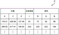
如图2所示,点群数据例如包括点各自的位置(x、y、z),该位置处的反射强度(I)以及该位置处的颜色(R、G、B)的信息。图2是表示点群数据D的一例的图。另外,点群数据D仪包括位置、反射强度以及颜色中的位置即可。此外,点群数据D是第1点群数据的一例。As shown in FIG. 2 , the point cloud data includes, for example, information on the respective positions (x, y, z) of the points, the reflection intensity (I) at the positions, and the colors (R, G, B) at the positions. FIG. 2 is a diagram showing an example of point cloud data D. FIG. In addition, the point cloud data D meter only needs to include the position, the reflection intensity, and the position in the color. In addition, the point cloud data D is an example of the first point cloud data.
图像生成装置20是基于新设备的三维信息以及从传感器10取得的点群数据D,生成用于判定新设备是否与现有设备发生干扰的图像并进行输出的处理的处理装置。图像生成装置20具有取得部21、控制部22、存储部23以及输出部24。另外,图像生成装置20是图像生成装置的一例。The
取得部21能够通信地与传感器10连接,从传感器10取得点群数据D。取得部21例如是无线通信模块或者无线通信电路,通过无线通信从传感器10取得点群数据D。另外,无线通信的通信规格没有特别限定。此外,无线通信是电波通信,但也可以是光通信等。The
控制部22基于从传感器10取得的多个位置的点群数据D,生成包括第1对象的虚拟空间。控制部22将所生成的虚拟空间的信息保存于存储部23。此外,控制部22基于新设置于工厂的新设备的三维信息以及表示该新设备的可动部的可动区域的信息(以下也记载为活动线信息),在虚拟空间上遍及可动区域对可动部进行扫描来确定被扫描的区域,生成与被扫描的区域对应的第3对象。另外,新设备的三维信息(三维数据)是表示新设备为静止状态时的三维形状的数据。三维信息例如可以是基于CAD数据的数据,也可以是基于由传感器10计测了静止状态的新设备的点群数据的数据。具体地说,三维信息是对新设备的CAD数据或者点群数据进行变换而得到的立体数据、表面数据或者多边形数据。此外,三维信息也可以是通过传感器10计测了静止状态的新设备的点群数据。另外,静止状态是指新设备的可动部未动的状态,例如可动部配置在初始位置的状态。此外,在本实施方式中,第3对象是与作为U形弯曲机的可动部mp的弯曲部的可动区域对应的对象。The
此外,控制部22进行将配置了新设备时用于确认与现有设备的干扰的信息经由输出部24输出到显示装置30的控制。具体地说,控制部22进行将用于在虚拟空间重叠显示第3对象的信息经由输出部24输出到显示装置30的控制。控制部22例如可以将虚拟空间以及第3对象的信息直接输出到显示装置30,也可以输出到收集该信息的服务器装置(未图示)。Further, the
具体地说,控制部22是微型计算机,但也可以通过处理器或者专用电路来实现。控制部22也可以通过微型计算机、处理器以及专用电路的两个以上的组合来实现。控制部22的具体方式没有特别限定。Specifically, the
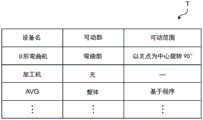
存储部23是保存控制部22执行的控制程序的存储装置。此外,存储部23保存新设备的三维信息以及该新设备的活动线信息。图3是表示本实施方式所涉及的活动线信息T的一例的图。The
如图3所示,活动线信息T包括表示设备名、可动部以及可动范围的信息。As shown in FIG. 3 , the active line information T includes information indicating a device name, a movable portion, and a movable range.
设备名是用于确定新设置的新设备的信息。在图3的例子中,设备名是表示装置的名称的例子,但并不局限于此,也可以是新设备的型号等。另外,新设备可以是如U形弯曲机那样为固定型的装置且其一部分可动的装置,也可以是AGV(Automated Guided Vehicle:无人搬运车)那样装置本身可移动的装置。The device name is information for determining the new device of the new setting. In the example of FIG. 3 , the device name is an example showing the name of the device, but it is not limited to this, and may be the model number of a new device or the like. In addition, the new equipment may be a fixed type device such as a U-bending machine and a part of which is movable, or a device itself such as an AGV (Automated Guided Vehicle) which can be moved.
可动部是用于确定在新设备中能够移动的部分的信息。在图3的例子中,示出了作为新设备(例如U形弯曲机)的一部分的弯曲部为可动部的例子。另外,可动部为“整体”是指该新设备整体进行动作(移动)。The movable part is information for specifying a part that can move in the new device. In the example of FIG. 3 , an example is shown in which the bending part, which is part of a new device (eg, a U-bender), is a movable part. In addition, "the whole" of the movable part means that the whole of the new device operates (moves).
可动范围是可动部的可动量、可动方向等与可动相关的信息。可动范围例如是产品说明书等中记载的值(例如最大的可动量),在决定了预定使用的可动量的情况下,也可以是预定使用的可动量。The movable range is information related to movement, such as the movement amount and movement direction of the movable portion. The movable range is, for example, a value described in a product manual or the like (for example, the maximum movable amount), and when the movable amount to be used is determined, it may be the movable amount to be used.
此外,存储部23也可以保存经由取得部21取得的信息(例如,点群数据等)。具体地说,存储部23也可以保存图2所示的点群数据D等。存储部23例如由半导体存储器等实现。In addition, the
输出部24基于控制部22的控制,将用于在虚拟空间重叠显示第3对象的信息输出到显示装置30。输出部24例如是无线通信模块或者无线通信电路,通过无线通信向显示装置30输出第3对象。另外,无线通信的通信规格没有特别限定。此外,无线通信是电波通信,但也可以是光通信等。The
另外,在上述中,对取得部21以及输出部24是无线通信模块或者无线通信电路的例子进行了说明,但并不局限于此,也可以是有线通信模块或者有线通信电路。此外,取得部21也可以经由USB(Universal Serial Bus:通用串行总线)存储器等记录介质取得点群数据。此外,输出部24也可以经由USB存储器等记录介质输出用于在虚拟空间重叠显示第3对象的信息。In the above, the
显示装置30将从图像生成装置20取得的信息显示为图像。图像包括照片、动画、插图以及文字等。显示装置30输出的图像由作业者进行视觉确认,用于确认是否发生了干扰等。显示装置30由液晶显示器等实现。显示装置30既可以是与个人计算机连接的显示器,也可以是智能手机或者平板电脑等便携终端等所具有的显示器,还可以是VR护目镜等所具有的显示器。The
显示装置30是输出从图像生成装置20取得的信息的输出装置的一例。另外,作为输出装置,显示系统1也可以代替显示装置30或者与显示装置30一起具备发声装置(例如扬声器)、投影仪等向对象物(例如屏幕)显示信息的装置、发光装置等以光(例如光的颜色)输出信息的装置等。The
[2.显示系统的动作][2. Display system actions]
接下来,一边参照图4~图8一边对上述那样的显示系统1中的动作进行说明。图4是表示本实施方式所涉及的显示系统1的动作的时序图。Next, operations in the above-described
如图4所示,传感器10将通过包括第1对象(现有设备)的现实空间的三维扫描而生成的点群数据D(参照图2)输出到图像生成装置20(S1)。传感器10将多个测定位置各自的点群数据D输出到图像生成装置20。As shown in FIG. 4 , the
图像生成装置20取得通过包含第1对象的现实空间的三维扫描而生成的点群数据(S2)。具体地说,取得部21取得从传感器10输出的点群数据。然后,控制部22基于在多个位置计测出的点群数据,生成包括第1对象的虚拟空间(S3)。控制部22从在多个位置计测出的点群数据生成一个虚拟空间的方法并不特别限定,也可以使用以往技术。因此,简化虚拟空间的生成方法的说明。The
控制部22例如将在多个位置分别计测出的多个点群数据的位置数据变换为同一三维空间中的位置数据。控制部22例如基于工厂内的标记位置的坐标(例如测量坐标),将多个点群数据配置于绝对坐标空间,由此生成一个虚拟空间。标记位置在由传感器10进行的多个位置的计测的每一个中,在进行该计测的位置的计测范围内至少设置一个。图5是在本实施方式所涉及的虚拟空间vs重叠了第2对象ob2的图。另外,图5表示从某视点观察虚拟空间vs的图像。The
如图5所示,控制部22基于经由取得部21取得的点群数据,生成包括第1对象ob1的虚拟空间vs。另外,在图5中,还图示了第2对象ob2,但在步骤S3中,生成除了第2对象ob2以外的虚拟空间vs。控制部22也可以将生成的虚拟空间vs保存于存储部23。As shown in FIG. 5 , the
接下来,控制部22取得第2对象ob2的三维数据(S4)。控制部22例如也可以通过读出保存于存储部23的第2对象ob2的三维数据,取得第2对象ob2的三维数据。然后,控制部22例如在虚拟空间vs重叠第2对象ob2。图5表示在虚拟空间vs重叠了第2对象ob2的图像。另外,以下,说明三维数据是立体数据的例子。Next, the
如图5所示,在虚拟空间vs重叠第2对象ob2。换言之,在由点群数据构成的三维空间中配置第2对象ob2。在此,在图5所示的图像中,第1对象ob1和第2对象ob2相互不干扰。然而,在图5所示的图像中,没有显示第2对象ob2所具有的可动部mp的可动区域。即,在图5所示的图像中,在第2对象ob2可动时,无法判定第1对象ob1与第2对象ob2是否发生干扰。As shown in FIG. 5 , the second object ob2 is superimposed on the virtual space vs. In other words, the second object ob2 is arranged in a three-dimensional space composed of point cloud data. Here, in the image shown in FIG. 5 , the first object ob1 and the second object ob2 do not interfere with each other. However, in the image shown in FIG. 5 , the movable area of the movable portion mp included in the second object ob2 is not displayed. That is, in the image shown in FIG. 5 , when the second object ob2 is movable, it cannot be determined whether or not the first object ob1 and the second object ob2 interfere with each other.
再次参照图4,因此,控制部22进行在虚拟空间vs重叠显示表示第2对象ob2的可动部mp的可动区域的数据的处理(S5~S8)。具体地说,控制部22取得第2对象ob2中的活动线信息T(S5)。控制部22例如也可以通过读出保存于存储部23的活动线信息T,取得与第2对象ob2对应的活动线信息T。另外,图5所示的虚线箭头表示可动部(弯曲部)mp的可动时的轨迹。该轨迹基于活动线信息T。Referring again to FIG. 4 , therefore, the
接下来,控制部22在虚拟空间上,遍及可动区域地扫描第2对象ob2,确定虚拟空间上的扫描区域。然后,生成所确定的扫描区域所涉及的第3对象ob3(S6)。在此,扫描区域是表示虚拟空间上的第2对象ob2的可动区域(可动范围)的区域。第3对象ob3是与第2对象ob2的可动部mp的可动区域对应的对象。由此,即使不实际使新设备移动,也能够将可动区域模型化。另外,例如,在第2对象ob2由立体数据构成的情况下,第3对象ob3由立体数据构成。Next, the
接下来,控制部22生成包括第1对象ob1和第3对象ob3的虚拟空间vs的显示图像(S7)。具体地说,控制部22生成从某视点观察在包括第1对象ob1的虚拟空间vs重叠第3对象ob3而得到的虚拟空间的图像即显示图像。图6是在图5所示的虚拟空间vs重叠了第3对象ob3的图。某视点是指例如能够验证第1对象ob1与第3对象ob3的干扰的视点。Next, the
如图6所示,控制部22在第2对象ob2的可动部mp的位置重叠与可动部mp的可动区域对应的第3对象ob3。As shown in FIG. 6 , the
再次参照图4,接下来,控制部22经由输出部24将生成的显示图像输出到显示装置30(S8)。控制部22例如将图6所示的图像作为显示图像输出到显示装置30。显示图像是图像的一例。Referring again to FIG. 4 , next, the
接下来,显示装置30取得从图像生成装置20输出的显示图像(S9),并显示所取得的显示图像(S10)。作业者通过确认显示于显示装置30的显示图像,能够判定第1对象ob1与第3对象ob3是否发生干扰。此外,通过在构成第1对象ob1的点群数据中包括颜色的信息,作业者能够根据与工厂内的实际情况接近的显示图像,判定第1对象ob1与第3对象ob3是否发生干扰。Next, the
另外,在步骤S4中,说明了第2对象ob2由立体数据构成、第3对象ob3也由立体数据构成的例子,但并不限定于此。例如,第2对象ob2可以由表面数据构成,扫描第2对象ob2而得到的第3对象ob3也可以由表面数据构成。此外,第2对象ob2也可以由多边形数据构成,扫描第2对象ob2而得到的第3对象ob3也由多边形数据构成。此外,第2对象ob2也可以由点群数据构成,扫描第2对象ob2而得到的第3对象ob3也由点群数据构成。In addition, in step S4, the example in which the 2nd object ob2 is comprised with the stereoscopic data and the 3rd object ob3 is comprised with the stereoscopic data was demonstrated, but it is not limited to this. For example, the second object ob2 may be composed of surface data, and the third object ob3 obtained by scanning the second object ob2 may be composed of surface data. In addition, the second object ob2 may be composed of polygon data, and the third object ob3 obtained by scanning the second object ob2 may also be composed of polygon data. In addition, the second object ob2 may be composed of point cloud data, and the third object ob3 obtained by scanning the second object ob2 may also be composed of point cloud data.
此外,第3对象ob3也可以是基于扫描了第2对象ob2的表面数据或者点群数据而构成的数据。例如,第3对象ob3也可以由对扫描了第2对象ob2的表面数据或者点群数据进行变换后的立体数据构成。In addition, the third object ob3 may be data configured based on the surface data or point cloud data of the second object ob2 scanned. For example, the third object ob3 may be composed of three-dimensional data obtained by converting the surface data or point cloud data obtained by scanning the second object ob2.
在此,作为一例,参照图7对扫描点群数据的方法进行说明。图7是表示点群数据的扫描的一例的图。具体地说,表示第2对象ob2的可动部的一部分。Here, as an example, a method of scanning point cloud data will be described with reference to FIG. 7 . FIG. 7 is a diagram showing an example of scanning of point cloud data. Specifically, a part of the movable part of the second object ob2 is shown.
如图7的(a)所示,首先,从构成第2对象ob2的多个点p(基于点群数据的点群)中,选择作为扫描对象的点群。在图7的(a)中,示出了虚线框内的点群是作为进行扫描的对象的点群的例子。即,图7的(a)的虚线框内的点群是构成可动部mp的点群。As shown in FIG. 7( a ), first, a point cloud to be scanned is selected from a plurality of points p (point cloud based on point cloud data) constituting the second object ob2 . In FIG. 7( a ), an example in which a point cloud within a dotted frame is a point cloud to be scanned is shown. That is, the point cloud within the dotted frame in FIG. 7( a ) is the point cloud constituting the movable portion mp.
另外,图7的(a)所示的虚线箭头表示可动部的活动线信息,虚线箭头的方向表示可动方向,虚线箭头的长度表示可动量。In addition, the broken line arrow shown in FIG.7(a) shows the movement line information of a movable part, the direction of the broken line arrow shows the moving direction, and the length of the broken line arrow shows the movable amount.
图7的(b)表示对在图7的(a)中选择的点群进行扫描的图。例如,通过沿着虚线箭头以规定间隔复制所选择的点群,从而对点群进行扫描。复制出的点群是第3对象ob3的一例。FIG. 7( b ) shows a view of scanning the point cloud selected in FIG. 7( a ). For example, the point group is scanned by duplicating the selected point group at predetermined intervals along the dotted arrow. The copied point group is an example of the third object ob3.
另外,即使在第2对象ob2为表面数据或者多边形数据的情况下,也能够通过同样的方法扫描第2对象ob2。In addition, even when the second object ob2 is surface data or polygon data, the second object ob2 can be scanned by the same method.
此外,控制部22在第3对象ob3由表面数据、多边形数据、或者点群数据构成的情况下,也可以按照第1对象ob1和第3对象ob3以相互不同的颜色显示的方式来生成显示图像。由此,作业者能够根据颜色的不同来判定第1对象ob1与第3对象ob3是否发生干扰,因此能够更容易地进行是否发生干扰的判定。作业者例如在通过点群数据生成第1对象ob1以及第3对象ob3双方的情况下,通过以相互不同的颜色显示第1对象ob1以及第3对象ob3,特别是能够容易地进行是否干扰的判定。In addition, when the third object ob3 is composed of surface data, polygon data, or point cloud data, the
接下来,参照图8,对图像生成装置20的动作进行说明。图8是表示本实施方式所涉及的图像生成装置20的动作的流程图。另外,图8所示的一系列动作是显示方法的一例。Next, the operation of the
如图8所示,控制部22读入包括由点群数据构成的第1对象ob1的虚拟空间vs(S21)。控制部22例如从存储部23读出在步骤S3中基于点群数据生成并保存于存储部23的包括第1对象ob1的虚拟空间vs。As shown in FIG. 8, the
接下来,控制部22读入配置于虚拟空间vs的第2对象ob2(S22)。控制部22例如从存储部23读出预先保存于存储部23的第2对象ob2,例如配置于虚拟空间vs。步骤S22相当于图4所示的步骤S4。Next, the
接下来,控制部22判定第2对象ob2是否可动(S23)。即,控制部22判定第2对象ob2是否具有可动的部分。控制部22例如基于保存于存储部23的活动线信息T所包括的“可动部”所表示的信息,判定第2对象ob2是否可动。另外,控制部22例如在存储部23保存有第2对象ob2的产品说明书信息(新设备的产品说明书信息)的情况下,也可以基于该产品说明书信息进行步骤S23的判定。Next, the
接下来,控制部22在判定为第2对象ob2是可动的情况下(S23:是),在虚拟空间上对第2对象ob2遍及可动区域进行扫描来确定扫描区域(S24)。然后,生成与第2对象ob2被扫描的扫描区域对应的第3对象ob3(S25)。具体地说,控制部22基于活动线信息T所包括的“可动范围”所表示的信息,在虚拟空间上扫描第2对象ob2的可动部mp并确定扫描区域。然后,生成与可动部mp的扫描区域对应的第3对象ob3。步骤S24以及S25相当于图4所示的步骤S6。Next, when the
接下来,控制部22将第3对象ob3配置在由点群数据构成的虚拟空间vs中(S26)。由此,生成包括第1对象ob1和第3对象ob3的虚拟空间vs的显示图像(例如图6所示的图像)。步骤S26相当于图4所示的步骤S7。此外,在步骤S26中生成的显示图像中也可以包括第2对象ob2。Next, the
此外,控制部22在判定为第2对象ob2不是可动的情况下(S23:否),将第2对象ob2配置在由点群数据构成的虚拟空间vs中(S27)。控制部22在不扫描第2对象ob2的情况下将该第2对象ob2配置于虚拟空间vs。由此,生成包括第1对象ob1和第2对象ob2的虚拟空间vs的显示图像(例如图5所示的图像)。Further, when it is determined that the second object ob2 is not movable ( S23 : NO), the
接下来,控制部22将在步骤S26或者S27中生成的显示图像输出到显示装置30(S28)。在步骤S26之后执行的步骤S28中输出的图像是用于将第3对象ob3重叠显示于虚拟空间vs的信息的一例。Next, the
作业者通过确认显示于显示装置30的显示图像,能够判定第1对象ob1与第3对象ob3是否发生了干扰。作业者例如能够基于显示于显示装置30的显示图像来研究新设备的设置位置等。The operator can determine whether or not the first object ob1 and the third object ob3 interfere with each other by checking the display image displayed on the
通过图像生成装置20执行上述那样的处理,即使在没有例如三维CAD那样的可动物体(在本实施方式中为新设备)的干扰检查功能的模拟软件中,也能够进行考虑了可动物体的动作的模拟。此外,在直接以点群数据处理第1对象ob1与例如第1对象由立体数据等构成相比能够减少处理量的情况下,能够减少用于生成图像的图像生成装置20中的处理量。即,根据上述的显示方法,能够提高图像的生成速度。By executing the above-described processing by the
此外,图8所示的步骤S21~S26的一系列的动作是用于生成显示图像的动作,也可以说是图像生成方法。In addition, a series of operations of steps S21 to S26 shown in FIG. 8 are operations for generating a display image, and can also be said to be an image generating method.
如上所述,本实施方式所涉及的显示方法是在包括由从现实空间取得的点群数据D构成的第1对象ob1的虚拟空间vs(第1虚拟空间的一例)配置第2对象ob2,并显示从某视点观察虚拟空间vs(第2虚拟空间的一例)而得到的图像的显示方法,包括:在虚拟空间上对第2对象ob2遍及该第2对象ob2的可动区域进行扫描来确定扫描区域,生成与第2对象ob2被扫描的区域对应的第3对象ob3,在配置有第2对象ob2的虚拟空间vs(第3虚拟空间的一例)配置第3对象ob3,输出用于显示从某视点观察虚拟空间vs(第3虚拟空间的一例)而得到的图像的信息。As described above, in the display method according to the present embodiment, the second object ob2 is arranged in the virtual space vs (an example of the first virtual space) including the first object ob1 composed of the point cloud data D acquired from the real space, and the second object ob2 is arranged. A display method for displaying an image obtained by observing virtual space vs (an example of a second virtual space) from a certain point of view, comprising: scanning a second object ob2 over a movable area of the second object ob2 on the virtual space to determine the scan area, generate a third object ob3 corresponding to the area where the second object ob2 is scanned, arrange the third object ob3 in the virtual space vs (an example of the third virtual space) where the second object ob2 is arranged, and output the output for displaying from a certain Information of an image obtained by viewing the virtual space vs (an example of the third virtual space) from the viewpoint.
此外,如上所述,本实施方式所涉及的图像生成装置20是在包括由从现实空间取得的点群数据D构成的第1对象ob1的虚拟空间vs(第1虚拟空间的一例)配置第2对象ob2,生成从某视点观察虚拟空间vs(第2虚拟空间的一例)而得到的图像的图像生成装置20,具备控制部22(电路的一例)和存储部23(存储器的一例)。控制部22使用存储部23,对第2对象ob2遍及该第2对象ob2的可动区域进行扫描来确定扫描区域,生成与第2对象ob2被扫描的区域对应的第3对象ob3,并配置在配置有第2对象ob2的虚拟空间vs(第2虚拟空间的一例),输出从某视点观察虚拟空间vs(第3虚拟空间)而得到的图像。In addition, as described above, the
另外,从某视点观察第2虚拟空间而得到的图像例如是图5所示的图像。此外,从某视点观察第3虚拟空间而得到的图像例如是图6所示的图像。In addition, an image obtained by observing the second virtual space from a certain viewpoint is, for example, the image shown in FIG. 5 . In addition, an image obtained by observing the third virtual space from a certain viewpoint is, for example, the image shown in FIG. 6 .
[3.效果等][3. Effects, etc.]
如以上说明的那样,本实施方式所涉及的显示方法是在包括由从现实空间取得的点群数据D构成的第1对象ob1的虚拟空间vs重叠显示第2对象ob2的显示方法,包括:对第2对象ob2遍及该第2对象ob2的可动区域进行扫描来确定扫描区域(S24),生成与第2对象ob2被扫描的区域对应的第3对象ob3(S25),并输出用于将第3对象ob3重叠显示于虚拟空间vs的信息(S28)。As described above, the display method according to the present embodiment is a display method for superimposing and displaying the second object ob2 in the virtual space including the first object ob1 composed of the point cloud data D acquired from the real space, and includes: The second object ob2 scans over the movable area of the second object ob2 to determine the scan area ( S24 ), generates a third object ob3 corresponding to the scanned area of the second object ob2 ( S25 ), and outputs the output for the second object ob2 3. The object ob3 is superimposed and displayed on the information of the virtual space vs (S28).
第1对象例如是与现有设备对应的对象,第2对象是与新设备对应的对象。The first object is, for example, an object corresponding to an existing device, and the second object is an object corresponding to a new device.
由此,能够在不移动新设备(第2对象)的可动部mp的情况下,即,能够在不取得新设备的时间序列数据的情况下,生成能够确认新设备与现有设备(第1对象)的干扰的图像。作业者通过观察由上述方法生成的图像,能够确认新设备与现有设备的干扰。因此,根据本实施方式所涉及的图像生成方法,能够不移动实际的装置地进行用于进行是否发生干扰的确认(验证)的显示。换言之,根据该图像生成方法,能够生成用于在不移动实际的装置的情况下进行是否发生干扰的确认(验证)的图像。Thereby, it is possible to generate a new device (the second object) that can be checked against the existing device without moving the movable part mp of the new device (the second object), that is, without acquiring the time-series data of the new device. 1 object) interference images. The operator can confirm the interference between the new equipment and the existing equipment by observing the image generated by the above method. Therefore, according to the image generation method according to the present embodiment, it is possible to perform display for checking (verification) whether or not interference has occurred without moving the actual device. In other words, according to this image generation method, it is possible to generate an image for checking (verification) whether or not interference occurs without moving the actual device.
此外,第2对象ob2是基于点群数据D生成的对象。In addition, the second object ob2 is an object generated based on the point cloud data D.
由此,即使在没有第2对象中的三维CAD数据等的情况下,也能够使用由3D扫描仪等计测到的点群数据来生成上述的图像。Thereby, even when there is no three-dimensional CAD data or the like in the second object, the above-described image can be generated using the point cloud data measured by a 3D scanner or the like.
此外,点群数据D包括通过计测现实空间中存在的三维物体而得到的颜色数据。In addition, the point cloud data D includes color data obtained by measuring a three-dimensional object existing in a real space.
由此,生成的图像成为接近现实空间的图像。因此,作业者能够更容易地进行第1对象ob1与第3对象ob3是否发生干扰的判定。Thereby, the generated image becomes an image close to the real space. Therefore, the operator can more easily determine whether or not the first object ob1 and the third object ob3 interfere with each other.
此外,如以上说明的那样,本实施方式所涉及的图像生成装置20是生成在包括由现实空间取得的点群数据D构成的第1对象ob1的虚拟空间vs重叠第2对象ob2而得到的虚拟空间的图像的图像生成装置20,具备控制部22(电路的一例)和存储部23(存储器的一例)。控制部22使用存储部23,对第2对象ob2遍及该第2对象ob2的可动区域进行扫描来确定扫描区域,生成与第2对象ob2被扫描的区域对应的第3对象ob3,输出用于将第3对象ob3重叠显示于虚拟空间vs的图像。此外,程序是用于使计算机执行上述的显示方法的程序。In addition, as described above, the
由此,起到与上述的显示方法同样的效果。具体地说,能够生成在不移动实际的装置的情况下进行是否发生干扰的确认的图像。Thereby, the same effect as the above-mentioned display method is exhibited. Specifically, it is possible to generate an image for confirming whether or not interference has occurred without moving the actual device.
(实施方式1的变形例)(Variation of Embodiment 1)
接下来,一边参照图9以及图10,一边对实施方式1的变形例1所涉及的显示系统进行说明。另外,本变形例所涉及的显示系统1以及图像生成装置20的结构与实施方式1所涉及的显示系统1以及图像生成装置20同样,省略说明。Next, a display system according to
图9是表示本变形例所涉及的图像生成装置20的动作的流程图。另外,在图9中的流程图中,对与图8中的流程图同样的处理标注相同的符号,省略或者简化说明。此外,以下,第3对象ob3由立体数据构成。FIG. 9 is a flowchart showing the operation of the
如图9所示,若控制部22将第3对象ob3配置于由点群数据构成的虚拟空间vs(S26),则判定第1对象ob1与第3对象ob3是否发生干扰(S31)。控制部22例如在构成第1对象ob1的点群的至少一个与第3对象ob3接触或者位于第3对象ob3的内部的情况下,判定为第1对象ob1与第3对象ob3发生干扰。As shown in FIG. 9 , when the
此外,控制部22例如也可以在第1对象ob1与第3对象ob3为规定的距离以下的情况下,判定为第1对象ob1与第3对象ob3发生干扰。另外,在此的干扰包括有可能发生干扰。规定的距离可以基于各种交叉决定,也可以是预先决定的值。各种交叉例如是构成第1对象ob1的点群数据的位置精度、第2对象ob2的尺寸公差、第3对象ob3的可动区域交叉以及第2对象ob2的设置交叉等。In addition, the
控制部22若判定为第1对象ob1与第3对象ob3发生干扰(S31:是),则生成表示第1对象ob1与第2对象ob2发生干扰的干扰信息(S32)。干扰信息是用于向作业者通知第1对象ob1与第2对象ob2发生干扰的信息。在本变形例中,干扰信息是用于以图像表示干扰的信息。另外,在显示系统1具备发声装置的情况下,干扰信息可以是用于以声音表示干扰的信息,在显示系统1具备发光装置的情况下,也可以是用于以发光颜色表示干扰的信息。When it is determined that the first object ob1 and the third object ob3 interfere ( S31 : YES), the
另外,控制部22在步骤S31中判定为有可能发生干扰的情况下,也可以生成表示在步骤S32中有可能发生干扰的信息。表示干扰的可能性的信息例如是表示第1对象ob1与第3对象ob3接近的信息,包括在干扰信息中。In addition, when it is determined in step S31 that there is a possibility of interference, the
接下来,控制部22将显示图像以及干扰信息经由输出部24输出到显示装置30(S33)。图10是表示本变形例所涉及的显示图像I的一例的图。Next, the
如图10所示,控制部22也可以将干扰信息重叠显示于显示图像I。控制部22例如也可以将表示干扰的位置的信息(图10所示的虚线圆)以及表示干扰的信息(图10所示的“干扰”)重叠显示于显示图像I。As shown in FIG. 10 , the
此外,控制部22在判定为第1对象ob1与第3对象ob3不发生干扰的情况下(S31:否),将在步骤S26中生成的显示图像经由输出部24输出到显示装置30(S28)。另外,控制部22在步骤S31中判定为“否”的情况下,也可以生成表示未发生干扰的非干扰信息,并与显示图像一起输出到显示装置30。Further, when it is determined that the first object ob1 and the third object ob3 do not interfere ( S31 : NO), the
如以上说明的那样,第3对象ob3由立体数据构成,本变形例所涉及的显示方法还包括:判定第1对象ob1是否与第3对象ob3发生干扰(S31),在判定为第1对象ob1与第3对象ob3发生干扰的情况下(S31:是),输出表示第1对象ob1与第2对象ob2发生干扰的信息(S33)。As described above, the third object ob3 is composed of stereoscopic data, and the display method according to this modification further includes determining whether or not the first object ob1 interferes with the third object ob3 (S31), and when determining whether the first object ob1 is the first object ob1 When there is interference with the third object ob3 ( S31 : YES), information indicating that the first object ob1 and the second object ob2 interfere with each other is output ( S33 ).
由此,能够使图像生成装置20等处理装置判定第1对象ob1与第3对象ob3是否发生干扰。作业者通过观察图像生成装置20的判定结果,能够容易地得知第1对象ob1与第3对象ob3是否发生干扰。Thereby, the processing apparatus, such as the
(实施方式2)(Embodiment 2)
接下来,一边参照图11~图13,一边对实施方式2所涉及的显示系统进行说明。另外,本实施方式所涉及的显示系统1以及图像生成装置20的结构与实施方式1所涉及的显示系统1以及图像生成装置20同样,省略说明。Next, a display system according to Embodiment 2 will be described with reference to FIGS. 11 to 13 . In addition, the configuration of the
在本实施方式中,对新设备是该新设备本身进行移动的移动体(例如AGV)的例子进行说明。显示系统1例如应用于导入了AGV时或者变更了AGV的行驶路径的情况等。In the present embodiment, an example in which the new device is a moving object (eg, an AGV) that moves by itself will be described. The
图11是表示本实施方式所涉及的图像生成装置20的动作的流程图。另外,在图11中的流程图中,对与图8中的流程图同样的处理标注相同的符号,省略或者简化说明。FIG. 11 is a flowchart showing the operation of the
如图11所示,控制部22读入配置于虚拟空间vs的第2对象ob2(S22)。控制部22也可以在虚拟空间vs配置第2对象ob2。图12是在本实施方式所涉及的虚拟空间vs重叠了第2对象ob2的图。As shown in FIG. 11, the
如图12所示,在包括由点群数据构成的第1对象ob1的虚拟空间vs重叠第2对象ob2。图12所示的图像表示某时间点的工厂内的各设备的位置。第2对象ob2例如是初始位置(移动前的位置)。另外,第2对象ob2由立体数据、表面数据、多边形数据、点群数据中的任一个构成。As shown in FIG. 12 , the second object ob2 is superimposed on the virtual space vs including the first object ob1 composed of point cloud data. The image shown in FIG. 12 shows the position of each device in the factory at a certain point in time. The second object ob2 is, for example, the initial position (position before movement). In addition, the second object ob2 is composed of any one of three-dimensional data, surface data, polygon data, and point cloud data.
另外,图12表示从某视点观察虚拟空间而得到的图像。在本实施方式中,某视点是从工厂的上方观察下方的视点。此外,图12的虚线箭头表示第2对象ob2的活动线信息,虚线箭头的方向表示移动方向(可动方向),虚线箭头的长度表示移动量(可动量)。In addition, FIG. 12 shows an image obtained by observing the virtual space from a certain viewpoint. In the present embodiment, a certain viewpoint is a viewpoint in which the lower part is viewed from the upper part of the factory. 12 shows the moving line information of the second object ob2, the direction of the dashed arrow represents the movement direction (movement direction), and the length of the dashed arrow represents the movement amount (momentum).
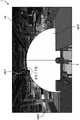
再次参照图11,接下来,控制部22若基于活动线信息T判定为第2对象ob2是可动的(S23:是),则在虚拟空间上对第2对象ob2遍及可动区域地进行扫描,确定扫描区域(S24)。控制部22遍及活动线信息T所包括的可动范围(例如图3所示的由程序确定的可动区域(参照图12所示的虚线箭头)地进行扫描。然后,控制部22生成与第2对象ob2被扫描的区域对应的第3对象ob3(S25),将生成的第3对象ob3配置于由点群数据构成的虚拟空间vs(S26)。即,控制部22生成包括第1对象ob1与第3对象ob3的虚拟空间vs的显示图像。图13是表示本实施方式所涉及的显示图像I的一例的图。具体地说,图13是从工厂的上方观察在图12所示的虚拟空间vs(第2虚拟空间的一例)重叠了第3对象ob3的虚拟空间vs(第3虚拟空间的一例)的图像。Referring again to FIG. 11 , next, when the
如图13所示,控制部22例如重叠表示第2对象ob2的从初始位置起的可动区域的第3对象ob3。As shown in FIG. 13 , the
再次参照图11,接下来,控制部22在基于点群数据D(例如显示图像I)来显示空闲区域或者作业者能够侵入的能侵入区域的情况下,判定是否存在空闲区域或者能侵入区域(S41)。控制部22例如也可以将与第1对象ob1、第2对象ob2以及第3对象ob3中的任一个都不重叠的区域判定为空闲区域或者能侵入区域。控制部22例如也可以将距离第1对象ob1、第2对象ob2以及第3对象ob3中的任一个为规定距离以上的区域判定为空闲区域或者能侵入区域。Referring again to FIG. 11 , next, the
另外,空闲区域是规定的宽度以上的区域,例如,是由作业者预先设定的宽度以上的区域。空闲区域例如也可以是用于确认是否能够配置其他设备的区域。此外,能够侵入的区域例如是作业者能够通过的区域。In addition, the free area is an area larger than a predetermined width, for example, an area larger than a width previously set by an operator. The free area may be, for example, an area for checking whether other devices can be placed. In addition, the intrudable area is, for example, an area through which an operator can pass.
接下来,控制部22在判定为存在空闲区域或者能侵入区域时(S41:是),生成表示空闲区域或者能侵入区域的区域信息(S42)。区域信息是用于向作业者通知空闲区域或者能侵入区域的位置以及范围等的信息。在本实施方式中,区域信息是用于以图像表示能侵入区域的信息。Next, when it is determined that there is a free area or an intrudable area ( S41 : YES), the
接下来,控制部22将显示图像I以及区域信息经由输出部24输出到显示装置30(S43)。如图13所示,控制部22也可以将区域信息a重叠显示于显示图像I。图13所示的区域信息a表示空闲区域。Next, the
此外,控制部22在判定为没有空闲区域或者能侵入区域时(S41:否),将在步骤S26中生成的显示图像(例如在图13中除去区域信息a后的图像)经由输出部24输出到显示装置30(S28)。另外,控制部22在步骤S41中判定为否的情况下,也可以生成表示没有空闲区域或者能侵入区域的区域信息,与显示图像I一起输出到显示装置30。In addition, when the
另外,在本实施方式中,也可以与实施方式1的变形例同样地,控制部22基于在步骤S26中生成的显示图像,进行第1对象ob1与第3对象ob3是否发生干扰的判定。而且,控制部22也可以在判定为第1对象ob1与第3对象ob3不发生干扰的情况下,执行步骤S41以后的处理。Also in this embodiment, as in the modification of
如以上说明的那样,本实施方式所涉及的显示方法还包括:在虚拟空间vs中,在基于点群数据D而显示空闲区域或者作业者能够侵入的能侵入区域的情况下,输出用于将除第3对象ob3以外的区域显示为空闲区域或者作业者能够侵入的区域的信息(S43)。As described above, the display method according to the present embodiment further includes: in the virtual space vs, when a free area or an intrudable area that can be intruded by an operator is displayed based on the point cloud data D, outputting an output for displaying Areas other than the third object ob3 are displayed as free areas or information on areas that the operator can enter ( S43 ).
由此,作业者在还存在空闲区域或者能够侵入的区域的情况下,能够获知该区域。作业者通过获知该区域,能够进一步研究追加的设备的配置或者工厂内的人的活动线。Thereby, when there is still a vacant area or an area that can be invaded, the operator can know the area. By knowing this area, the operator can further study the arrangement of additional equipment or the movement lines of people in the factory.
(其他实施方式)(Other Embodiments)
以上,对各实施方式以及变形例(以下也记载为实施方式等)进行了说明,但本发明并不限定于这样的实施方式等。As mentioned above, although each embodiment and modification (it is also described as an embodiment etc. hereinafter) were described, the present invention is not limited to such an embodiment and the like.
例如,在实施方式1的变形例中,说明了控制部22在判定为第1对象ob1与第3对象ob3发生干扰的情况下(图9所示的S31:是),生成表示干扰的干扰信息的例子,但并不限定于此。控制部22例如可以将表示可动量为多少的情况下发生了干扰(例如可动部mp以支点s为中心旋转了多少度时发生干扰)的信息作为干扰信息输出到显示装置30。控制部22也可以基于可动部mp的初始位置(可动前的位置)和发生了与第1对象ob1的干扰的位置,计算干扰时的可动量。For example, in the modification of
此外,在实施方式1中,控制部22还可以基于第1对象ob1、第2对象ob2以及第3对象ob3,判定是否存在作业者能够侵入的区域,在存在能侵入区域的情况下,也可以将表示该能侵入区域的信息与显示图像一起输出到显示装置30。In addition, in
此外,在上述实施方式等中,对控制部22向显示装置30输出在虚拟空间vs重叠了第3对象ob3的图像的例子进行了说明,但并不限定于此。控制部22例如也可以将包括第1对象ob1的虚拟空间vs的图像和包括第3对象ob3的图像在不同的定时输出到显示装置30。而且,显示装置30也可以在不同的定时取得的虚拟空间vs以及第3对象ob3的图像中,在虚拟空间vs重叠第3对象ob3,并显示重叠后的图像。Further, in the above-described embodiments and the like, the example in which the
此外,在上述实施方式等中,对控制部22生成从一个视点观察包括第1对象ob1以及第3对象ob3的虚拟空间vs而得到的图像作为显示图像的例子进行了说明,但并不限定于此。控制部22也可以生成从两个以上相互不同的视点观察该虚拟空间vs而得到的两个以上的图像作为显示图像。In addition, in the above-described embodiment and the like, the
此外,在上述实施方式等中,对第1对象ob1(现有设备)是不可动的装置等的例子进行了说明,但也可以包括可动的装置。控制部22在第1对象ob1可动的情况下,还可以在虚拟空间上对该第1对象ob1遍及可动区域地进行扫描,生成与扫描区域相关的第4对象,生成包括第4对象的虚拟空间的显示图像。即,显示图像也可以包括第1对象ob1、第2对象ob2、第3对象ob3以及第4对象。作业者能够根据第1对象ob1以及第4对象、第3对象ob3来验证是否发生干扰。另外,第4对象是基于点群数据的对象。In addition, in the above-mentioned embodiment and the like, the example in which the first object ob1 (existing equipment) is an immovable device or the like has been described, but a movable device may be included. When the first object ob1 is movable, the
此外,在上述实施方式等中,对与图像生成装置20连接的显示装置30为1台的例子进行了说明,但也可以是2台以上。In addition, in the above-described embodiment and the like, the example in which the number of
此外,图1所示的框图中的功能块的分割是一例,也可以将多个功能块作为一个功能块来实现,或者将一个功能块分割为多个,或者将一部分功能转移到其他功能块。此外,也可以由单一硬件或者软件并行或者分时地处理具有相似功能的多个功能块的功能。In addition, the division of the functional blocks in the block diagram shown in FIG. 1 is an example, and a plurality of functional blocks may be implemented as a single functional block, a single functional block may be divided into a plurality of functional blocks, or some functions may be transferred to other functional blocks. . Furthermore, the functions of a plurality of functional blocks having similar functions may also be processed in parallel or time-sharing by a single piece of hardware or software.
此外,在上述实施方式等中,图像生成装置20由单一的装置实现,但也可以由相互连接的多个装置实现。此外,在上述实施方式中,对图像生成装置20和显示装置30是不同的装置的例子进行了说明,但图像生成装置20也可以具备显示装置30。In addition, in the above-described embodiments and the like, the
此外,上述实施方式等中的显示系统1所具备的装置之间的通信方法没有特别限定。在装置之间可以进行无线通信,也可以进行有线通信。In addition, the communication method between the apparatuses with which the
此外,流程图中的各步骤被执行的顺序是为了具体说明本发明而例示的顺序,也可以是上述以外的顺序。例如,上述步骤的一部分既可以与其他步骤同时(并行)执行,也可以与其他的步骤调换顺序来执行。In addition, the order in which each step in the flowchart is performed is the order exemplified in order to specifically explain the present invention, and an order other than the above-mentioned order may be used. For example, a part of the above steps may be performed simultaneously (parallel) with other steps, or may be performed in a reverse order with other steps.
此外,上述实施方式等中的图像生成装置20所具备的结构要素的一部分或者全部可以由一个系统LSI(Large Scale Integration:大规模集成电路)构成。例如,图像生成装置20也可以由具有控制部22等处理部的系统LSI构成。In addition, some or all of the constituent elements included in the
系统LSI是将多个构成部集成到一个芯片上而制造的超多功能LSI,具体地说是包括微处理器、ROM(Read Only Memory:只读存储器),RAM(Random Access Memory:随机存取存储器)等而构成的计算机系统。在ROM存储有计算机程序。通过微处理器按照计算机程序进行动作,系统LSI实现其功能。A system LSI is an ultra-multifunctional LSI manufactured by integrating multiple components into one chip, specifically including a microprocessor, a ROM (Read Only Memory), and a RAM (Random Access Memory: random access). memory), etc. A computer program is stored in the ROM. The function of the system LSI is realized by the microprocessor operating in accordance with the computer program.
另外,在此,设为系统LSI,但根据集成度的不同,有时也称为IC、LSI、超级LSI、特大LSI。此外,集成电路化的手法不限于LSI,也可以通过专用电路或者通用处理器来实现。也可以利用在LSI制造后能够编程的FPGA(Field Programmable Gate Array:现场可编程门阵列)、或者能够对LSI内部的电路单元的连接、设定进行重构的可重构处理器。In addition, although the system LSI is used here, it may be called an IC, an LSI, a super LSI, or an extra-large LSI depending on the degree of integration. In addition, the method of integrating the circuit is not limited to the LSI, and may be realized by a dedicated circuit or a general-purpose processor. An FPGA (Field Programmable Gate Array) that can be programmed after the LSI is manufactured, or a reconfigurable processor that can reconfigure the connections and settings of circuit cells inside the LSI can also be used.
进而,若随着半导体技术的进步或者派生的其他技术而出现能够替代LSI的集成电路化的技术,则当然也可以使用该技术进行功能块的集成化。有可能应用生物技术等。Furthermore, if a technology for integrating integrated circuits that can replace LSIs emerges with the advancement of semiconductor technology or other derived technologies, it is of course possible to use this technology to integrate functional blocks. It is possible to apply biotechnology etc.
此外,本发明的一方式也可以是使计算机执行显示方法所包括的特征性的各步骤的计算机程序。此外,本发明的一方式电可以是记录有这样的计算机程序的计算机可读取的非易性记录介质。Furthermore, one aspect of the present invention may be a computer program for causing a computer to execute each characteristic step included in the display method. Furthermore, one embodiment of the present invention may be a computer-readable non-transitory recording medium on which such a computer program is recorded.
另外,在上述实施方式等中,各结构要素也可以由专用的硬件构成,或者通过执行适合于各结构要素的软件程序来实现。各结构要素也可以通过CPU或者处理器等程序执行部读出并执行硬盘或者半导体存储器等记录介质中记录的软件程序来实现。In addition, in the above-described embodiments and the like, each component may be constituted by dedicated hardware, or may be realized by executing a software program suitable for each component. Each component can also be realized by a program execution unit such as a CPU or a processor reading and executing a software program recorded on a recording medium such as a hard disk or a semiconductor memory.
另外,本发明的包括的或者具体的方式可以通过系统、方法、集成电路、计算机程序或者计算机可读取的CD-ROM等记录介质来实现,也可以通过系统、集成电路、计算机程序以及记录介质的任意组合来实现。In addition, the included or specific modes of the present invention can be implemented by systems, methods, integrated circuits, computer programs, or recording media such as computer-readable CD-ROMs, and can also be implemented by systems, integrated circuits, computer programs, and recording media. any combination of .
根据本发明的一方式所涉及的显示方法等,能够在不移动实际的装置的情况下进行用于确认是否发生干扰的显示。According to the display method and the like according to one aspect of the present invention, it is possible to perform display for checking whether or not interference has occurred without moving the actual device.
此外,通过对实施方式实施本领域技术人员能够想到的各种变形而得到的方式、或者在不脱离本发明的主旨的范围内任意地组合各实施方式中的结构要素以及功能来实现的方式也包括在本发明中。In addition, forms obtained by applying various modifications that can be conceived by those skilled in the art to the embodiments, or forms realized by arbitrarily combining constituent elements and functions in each embodiment without departing from the gist of the present invention may also be implemented. Included in the present invention.
Claims (6)
Applications Claiming Priority (2)
| Application Number | Priority Date | Filing Date | Title |
|---|---|---|---|
| JP2019-110846 | 2019-06-14 | ||
| JP2019110846AJP2020204805A (en) | 2019-06-14 | 2019-06-14 | Display method, image generation device, and program |
Publications (1)
| Publication Number | Publication Date |
|---|---|
| CN112087550Atrue CN112087550A (en) | 2020-12-15 |
Family
ID=73734977
Family Applications (1)
| Application Number | Title | Priority Date | Filing Date |
|---|---|---|---|
| CN202010509804.XAPendingCN112087550A (en) | 2019-06-14 | 2020-06-05 | Display method and image generation device |
Country Status (3)
| Country | Link |
|---|---|
| US (1) | US20200394844A1 (en) |
| JP (1) | JP2020204805A (en) |
| CN (1) | CN112087550A (en) |
Families Citing this family (3)
| Publication number | Priority date | Publication date | Assignee | Title |
|---|---|---|---|---|
| JP7501891B2 (en)* | 2020-04-10 | 2024-06-18 | 日本電気通信システム株式会社 | Information processing device, design method, and program |
| JP6874197B1 (en)* | 2020-08-27 | 2021-05-19 | パシフィックコンサルタンツ株式会社 | Equipment management program, equipment management method, and equipment management system |
| JP2023161960A (en)* | 2022-04-26 | 2023-11-08 | 三菱電機株式会社 | Layout device, layout method, and program |
Family Cites Families (9)
| Publication number | Priority date | Publication date | Assignee | Title |
|---|---|---|---|---|
| JP3383563B2 (en)* | 1997-12-18 | 2003-03-04 | 富士通株式会社 | Object movement simulation device |
| JP2002056406A (en)* | 2000-08-08 | 2002-02-22 | Clim Ncd:Kk | Assembly process support system and recording medium recorded with its data |
| JP2003345839A (en)* | 2002-05-24 | 2003-12-05 | Honda Motor Co Ltd | 3D model creation method and system |
| JP4677273B2 (en)* | 2004-06-29 | 2011-04-27 | キヤノン株式会社 | Information processing method and information processing apparatus |
| JP5830004B2 (en)* | 2012-12-11 | 2015-12-09 | 株式会社日立製作所 | 3D model generation apparatus, 3D model generation method, and 3D model generation program |
| JP6526488B2 (en)* | 2015-06-16 | 2019-06-05 | 株式会社日立製作所 | Three-dimensional model generation device, component member determination method, and program |
| JP6520742B2 (en)* | 2016-02-02 | 2019-05-29 | トヨタ自動車株式会社 | High design method, high design device and program |
| JP6638519B2 (en)* | 2016-03-30 | 2020-01-29 | 三菱自動車エンジニアリング株式会社 | Production line development support device, development support method, and development support program |
| JP2018045465A (en)* | 2016-09-14 | 2018-03-22 | キヤノンマーケティングジャパン株式会社 | Information processing device, information processing system, control method thereof, and program |
- 2019
- 2019-06-14JPJP2019110846Apatent/JP2020204805A/enactivePending
- 2020
- 2020-06-04USUS16/893,061patent/US20200394844A1/ennot_activeAbandoned
- 2020-06-05CNCN202010509804.XApatent/CN112087550A/enactivePending
Also Published As
| Publication number | Publication date |
|---|---|
| JP2020204805A (en) | 2020-12-24 |
| US20200394844A1 (en) | 2020-12-17 |
Similar Documents
| Publication | Publication Date | Title |
|---|---|---|
| KR100785594B1 (en) | Image process apparatus | |
| CN112087550A (en) | Display method and image generation device | |
| JP7170023B2 (en) | DAMAGE DATA EDITING DEVICE, DAMAGE DATA EDITING METHOD, PROGRAM, AND SYSTEM | |
| CN104908038A (en) | Robot simulation system which simulates takeout process of workpieces | |
| JP5313572B2 (en) | Method and apparatus for investigating actual measurement data of components | |
| JP2007334678A (en) | Robot simulation device | |
| JP5762913B2 (en) | Three-dimensional data processing apparatus, method and program | |
| JP7146013B2 (en) | Server device, image processing method, and program | |
| JP2016090548A (en) | Crack information collection method and crack information collection program | |
| JPWO2018155590A1 (en) | IDENTIFICATION DEVICE, IDENTIFICATION METHOD, AND PROGRAM FOR IDENTIFYING THE LOCATION OF A WALLEN IN A TUNNEL IN A PHOTOGRAPH IMAGE | |
| JP6902332B2 (en) | Defect information acquisition system | |
| JP2023065371A (en) | MANUFACTURING SUPPORT SYSTEM, METHOD, AND PROGRAM | |
| JP2018088139A (en) | 3D space visualization device, 3D space visualization method and program | |
| CN108431816B (en) | Controlling a device with respect to a digital model of the device | |
| US20120084061A1 (en) | Three dimensional simulation method | |
| CN118786463B (en) | Recording medium, display data generating device, and display data generating method | |
| CN101932981A (en) | Method and device for visualizing an automated device including a workpiece | |
| JP2020134221A (en) | Scanning route generation device, scanning route generation program, scanning route generation method, and appearance inspection system | |
| JP2020003300A (en) | Appearance inspection system, method for displaying result of appearance inspection, and program for displaying result of appearance inspection | |
| KR101792701B1 (en) | Apparatus and method for inspecting drawing | |
| US20230339103A1 (en) | Information processing system, information processing method, robot system, robot system control method, article manufacturing method using robot system, and recording medium | |
| JP6350988B2 (en) | Camera for diagnosing bridge damage | |
| JP2023100502A (en) | Inspection system and inspection method | |
| JP2008209194A (en) | 3D shape measurement method | |
| JP2005208868A (en) | Point cloud data comparison method, point cloud data comparison device, point cloud data acquisition device, and point cloud data comparison system |
Legal Events
| Date | Code | Title | Description |
|---|---|---|---|
| PB01 | Publication | ||
| PB01 | Publication | ||
| WD01 | Invention patent application deemed withdrawn after publication | Application publication date:20201215 | |
| WD01 | Invention patent application deemed withdrawn after publication |