CN112086711A - Battery box - Google Patents
Battery boxDownload PDFInfo
- Publication number
- CN112086711A CN112086711ACN202010953665.XACN202010953665ACN112086711ACN 112086711 ACN112086711 ACN 112086711ACN 202010953665 ACN202010953665 ACN 202010953665ACN 112086711 ACN112086711 ACN 112086711A
- Authority
- CN
- China
- Prior art keywords
- battery
- battery box
- casing
- fan
- cells
- Prior art date
- Legal status (The legal status is an assumption and is not a legal conclusion. Google has not performed a legal analysis and makes no representation as to the accuracy of the status listed.)
- Granted
Links
- 238000009423ventilationMethods0.000claimsdescription17
- 238000005192partitionMethods0.000claimsdescription9
- 230000000694effectsEffects0.000abstractdescription15
- 238000001816coolingMethods0.000abstractdescription10
- 238000004519manufacturing processMethods0.000abstractdescription6
- 238000009826distributionMethods0.000abstractdescription2
- 230000017525heat dissipationEffects0.000description16
- XAGFODPZIPBFFR-UHFFFAOYSA-NaluminiumChemical compound[Al]XAGFODPZIPBFFR-UHFFFAOYSA-N0.000description10
- 229910052782aluminiumInorganic materials0.000description10
- 238000000034methodMethods0.000description8
- 238000010586diagramMethods0.000description5
- 238000004146energy storageMethods0.000description5
- 239000011120plywoodSubstances0.000description3
- WHXSMMKQMYFTQS-UHFFFAOYSA-NLithiumChemical compound[Li]WHXSMMKQMYFTQS-UHFFFAOYSA-N0.000description2
- 229910052744lithiumInorganic materials0.000description2
- 239000000463materialSubstances0.000description2
- 238000004891communicationMethods0.000description1
- 238000005265energy consumptionMethods0.000description1
- 238000005516engineering processMethods0.000description1
Images


Classifications
- H—ELECTRICITY
- H01—ELECTRIC ELEMENTS
- H01M—PROCESSES OR MEANS, e.g. BATTERIES, FOR THE DIRECT CONVERSION OF CHEMICAL ENERGY INTO ELECTRICAL ENERGY
- H01M10/00—Secondary cells; Manufacture thereof
- H01M10/05—Accumulators with non-aqueous electrolyte
- H01M10/058—Construction or manufacture
- H—ELECTRICITY
- H01—ELECTRIC ELEMENTS
- H01M—PROCESSES OR MEANS, e.g. BATTERIES, FOR THE DIRECT CONVERSION OF CHEMICAL ENERGY INTO ELECTRICAL ENERGY
- H01M10/00—Secondary cells; Manufacture thereof
- H01M10/60—Heating or cooling; Temperature control
- H01M10/61—Types of temperature control
- H01M10/613—Cooling or keeping cold
- H—ELECTRICITY
- H01—ELECTRIC ELEMENTS
- H01M—PROCESSES OR MEANS, e.g. BATTERIES, FOR THE DIRECT CONVERSION OF CHEMICAL ENERGY INTO ELECTRICAL ENERGY
- H01M10/00—Secondary cells; Manufacture thereof
- H01M10/60—Heating or cooling; Temperature control
- H01M10/61—Types of temperature control
- H01M10/617—Types of temperature control for achieving uniformity or desired distribution of temperature
- H—ELECTRICITY
- H01—ELECTRIC ELEMENTS
- H01M—PROCESSES OR MEANS, e.g. BATTERIES, FOR THE DIRECT CONVERSION OF CHEMICAL ENERGY INTO ELECTRICAL ENERGY
- H01M10/00—Secondary cells; Manufacture thereof
- H01M10/60—Heating or cooling; Temperature control
- H01M10/62—Heating or cooling; Temperature control specially adapted for specific applications
- H01M10/627—Stationary installations, e.g. power plant buffering or backup power supplies
- H—ELECTRICITY
- H01—ELECTRIC ELEMENTS
- H01M—PROCESSES OR MEANS, e.g. BATTERIES, FOR THE DIRECT CONVERSION OF CHEMICAL ENERGY INTO ELECTRICAL ENERGY
- H01M10/00—Secondary cells; Manufacture thereof
- H01M10/60—Heating or cooling; Temperature control
- H01M10/64—Heating or cooling; Temperature control characterised by the shape of the cells
- H01M10/647—Prismatic or flat cells, e.g. pouch cells
- H—ELECTRICITY
- H01—ELECTRIC ELEMENTS
- H01M—PROCESSES OR MEANS, e.g. BATTERIES, FOR THE DIRECT CONVERSION OF CHEMICAL ENERGY INTO ELECTRICAL ENERGY
- H01M10/00—Secondary cells; Manufacture thereof
- H01M10/60—Heating or cooling; Temperature control
- H01M10/65—Means for temperature control structurally associated with the cells
- H01M10/655—Solid structures for heat exchange or heat conduction
- H01M10/6554—Rods or plates
- H01M10/6555—Rods or plates arranged between the cells
- H—ELECTRICITY
- H01—ELECTRIC ELEMENTS
- H01M—PROCESSES OR MEANS, e.g. BATTERIES, FOR THE DIRECT CONVERSION OF CHEMICAL ENERGY INTO ELECTRICAL ENERGY
- H01M10/00—Secondary cells; Manufacture thereof
- H01M10/60—Heating or cooling; Temperature control
- H01M10/65—Means for temperature control structurally associated with the cells
- H01M10/655—Solid structures for heat exchange or heat conduction
- H01M10/6556—Solid parts with flow channel passages or pipes for heat exchange
- H01M10/6557—Solid parts with flow channel passages or pipes for heat exchange arranged between the cells
- H—ELECTRICITY
- H01—ELECTRIC ELEMENTS
- H01M—PROCESSES OR MEANS, e.g. BATTERIES, FOR THE DIRECT CONVERSION OF CHEMICAL ENERGY INTO ELECTRICAL ENERGY
- H01M10/00—Secondary cells; Manufacture thereof
- H01M10/60—Heating or cooling; Temperature control
- H01M10/65—Means for temperature control structurally associated with the cells
- H01M10/656—Means for temperature control structurally associated with the cells characterised by the type of heat-exchange fluid
- H01M10/6561—Gases
- H01M10/6563—Gases with forced flow, e.g. by blowers
- Y—GENERAL TAGGING OF NEW TECHNOLOGICAL DEVELOPMENTS; GENERAL TAGGING OF CROSS-SECTIONAL TECHNOLOGIES SPANNING OVER SEVERAL SECTIONS OF THE IPC; TECHNICAL SUBJECTS COVERED BY FORMER USPC CROSS-REFERENCE ART COLLECTIONS [XRACs] AND DIGESTS
- Y02—TECHNOLOGIES OR APPLICATIONS FOR MITIGATION OR ADAPTATION AGAINST CLIMATE CHANGE
- Y02P—CLIMATE CHANGE MITIGATION TECHNOLOGIES IN THE PRODUCTION OR PROCESSING OF GOODS
- Y02P70/00—Climate change mitigation technologies in the production process for final industrial or consumer products
- Y02P70/50—Manufacturing or production processes characterised by the final manufactured product
Landscapes
- Engineering & Computer Science (AREA)
- Manufacturing & Machinery (AREA)
- Chemical & Material Sciences (AREA)
- Chemical Kinetics & Catalysis (AREA)
- Electrochemistry (AREA)
- General Chemical & Material Sciences (AREA)
- Secondary Cells (AREA)
- Battery Mounting, Suspending (AREA)
Abstract
Description
Translated fromChinese技术领域technical field
本发明涉及储能设备技术领域,尤其涉及一种电池箱。The present invention relates to the technical field of energy storage devices, in particular to a battery box.
背景技术Background technique
目前为保护生态环境,风能、太阳能等可再生能源得到了大力发展,与之相应的储能技术也随着成为研究的热点。其中以锂电池储能的应用最为显著。在锂电储能应用里面,普遍采用自然散热或强制风冷的电池箱进行储能系统的集成设计。而在强制风冷电池箱的设计上又存在电池箱尺寸大、散热能耗大、电池箱内部温差较大等问题。At present, in order to protect the ecological environment, renewable energy sources such as wind energy and solar energy have been vigorously developed, and the corresponding energy storage technology has also become a research hotspot. Among them, the application of lithium battery energy storage is the most significant. In lithium battery energy storage applications, natural heat dissipation or forced air cooling battery boxes are generally used for the integrated design of energy storage systems. However, in the design of the forced air-cooled battery box, there are problems such as large size of the battery box, large heat dissipation energy consumption, and large temperature difference inside the battery box.
发明内容SUMMARY OF THE INVENTION
本发明的目的在于提出一种电池箱,该电池箱的尺寸较小,散热效果较高,内部温差较小。The purpose of the present invention is to provide a battery box, which has a small size, a high heat dissipation effect and a small internal temperature difference.
为实现上述技术效果,本发明的技术方案如下:For realizing above-mentioned technical effect, technical scheme of the present invention is as follows:
本发明公开了一种电池箱,包括:壳体,所述壳体的侧壁上设有进风口和出风口;电池模组,所述电池模组设在所述壳体内,所述电池模组包括沿所述壳体的高度方向多个依次叠加的电芯,且相邻的两个电芯之间具有夹板,所述夹板具有通风孔;风机,所述风机配合在所述出风口处;其中:在远离所述风机的方向上,所述电池模组的高度逐渐增大。The invention discloses a battery box, comprising: a casing, the side wall of the casing is provided with an air inlet and an air outlet; a battery module, the battery module is arranged in the casing, the battery module is The group includes a plurality of battery cells stacked in sequence along the height direction of the casing, and a splint is arranged between two adjacent battery cores, and the splint has a ventilation hole; a fan, the fan is matched at the air outlet ; wherein: in the direction away from the fan, the height of the battery module increases gradually.
在一些实施例中,所述电池模组还包括上端板和下端板,所述上端板连接在最上方的所述电芯的顶壁上,所述下端板连接在最下方的所述电芯的底壁上;其中:在远离所述风机的方向上,多个所述电池模组的所述下端板的高度逐渐增大。In some embodiments, the battery module further includes an upper end plate and a lower end plate, the upper end plate is connected to the top wall of the uppermost cell, and the lower end plate is connected to the lowermost cell On the bottom wall of the battery module; wherein: in the direction away from the fan, the heights of the lower end plates of the plurality of battery modules gradually increase.
在一些实施例中,多个所述电池模组分成两个电池组,每个所述电池组内的多个所述电池模组在远离所述风机的方向上依次排布,且每个所述电池组的多个所述电池模组的高度逐渐增大,所述电池箱还包括分隔板,所述分隔板位于两个所述电池组之间。In some embodiments, a plurality of the battery modules are divided into two battery packs, the plurality of the battery modules in each battery pack are sequentially arranged in a direction away from the fan, and each battery pack is arranged in sequence in a direction away from the fan. The heights of the plurality of battery modules of the battery pack are gradually increased, and the battery box further includes a partition plate, and the partition plate is located between the two battery packs.
在一些可选的实施例中,每个所述电池组内的多个所述电池模组依次串联,两个所述电池组串联连接;所述电池箱还包括正极接头和负极接头,所述正极接头和所述负极接头分别与两个所述电池组电连接,所述正极接头和所述负极接头位于所述壳体的同一侧。In some optional embodiments, a plurality of the battery modules in each of the battery packs are connected in series in sequence, and two of the battery packs are connected in series; the battery box further includes a positive terminal and a negative terminal. The positive terminal and the negative terminal are respectively electrically connected to the two battery packs, and the positive terminal and the negative terminal are located on the same side of the casing.
在一些实施例中,相邻的两个所述电芯之间的夹板为多个,多个所述夹板间隔分布。In some embodiments, there are multiple clamping plates between two adjacent battery cells, and the multiple clamping plates are distributed at intervals.
在一些实施例中,所述进风口包括第一进口,所述第一进口与所述进风口分别设在所述壳体的相对设置的两个侧壁上。In some embodiments, the air inlet includes a first inlet, and the first inlet and the air inlet are respectively provided on two opposite side walls of the housing.
在一些可选的实施例中,所述夹板上沿其长度方向设置有所述通风孔,所述通风孔的一端朝向所述出风口设置,另一端朝向所述第一进口设置。In some optional embodiments, the clamping plate is provided with the ventilation hole along the length direction thereof, one end of the ventilation hole is arranged toward the air outlet, and the other end is arranged toward the first inlet.
在一些实施例中,所述进风口还包括第二进口,所述第二进口与所述出风口设在所述壳体的相邻设置的两个侧壁上。In some embodiments, the air inlet further includes a second inlet, and the second inlet and the air outlet are provided on two adjacent side walls of the housing.
在一些可选的实施例中,所述第二进口为多个,多个所述第二进口位于所述壳体的相对设置的两个侧壁上。In some optional embodiments, there are multiple second inlets, and the plurality of second inlets are located on two opposite side walls of the housing.
在一些可选的实施例中,每个所述第二进口均对应相邻两个电池模组的之间的间隙设置。In some optional embodiments, each of the second inlets is disposed corresponding to a gap between two adjacent battery modules.
本发明实施例的电池箱,由于相邻的两个电芯之间设置具有通风孔的夹板,在远离风机的方向上,多个电池模组的高度逐渐增大,实现了电芯在气流流通的方向上错开分布,增大了冷却气流的湍流程度,提升了电池箱的散热效果,降低了多个电池模组之间的温差,确保了整个电池箱的使用可靠性;由于电池模组的多个电芯沿壳体的高度方向依次叠加,在确保电池箱的能量密度的前提下,缩小了电池箱的体积,降低了电池箱的制造成本。In the battery box of the embodiment of the present invention, since a splint with ventilation holes is arranged between two adjacent battery cells, the heights of the plurality of battery modules gradually increase in the direction away from the fan, which realizes the air circulation of the battery cells. The staggered distribution in the direction of the cooling airflow increases the turbulence of the cooling airflow, improves the heat dissipation effect of the battery box, reduces the temperature difference between multiple battery modules, and ensures the reliability of the entire battery box; A plurality of battery cells are stacked in sequence along the height direction of the casing, on the premise of ensuring the energy density of the battery box, the volume of the battery box is reduced, and the manufacturing cost of the battery box is reduced.
本发明的附加方面和优点将在下面的描述中部分给出,部分将从下面的描述中变得明显,或通过本发明的实践了解到。Additional aspects and advantages of the present invention will be set forth, in part, from the following description, and in part will be apparent from the following description, or may be learned by practice of the invention.
附图说明Description of drawings
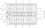
图1是本发明实施例的电池箱的结构示意图。FIG. 1 is a schematic structural diagram of a battery box according to an embodiment of the present invention.
图2是本发明实施例的电池箱拆去壳体的顶壁的结构示意图。2 is a schematic structural diagram of a battery box according to an embodiment of the present invention with the top wall of the casing removed.
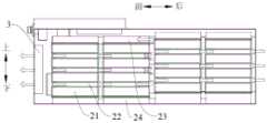
图3是本发明实施例的电池箱拆去壳体的结构示意图。FIG. 3 is a schematic structural diagram of the battery box according to the embodiment of the present invention with the casing removed.
图4是本发明实施例的电池箱内部的气流流向示意图。FIG. 4 is a schematic diagram of the airflow inside the battery box according to the embodiment of the present invention.
图5是本发明实施例的电池箱内部的另一方向的气流流向示意图。FIG. 5 is a schematic diagram of the airflow in another direction inside the battery box according to the embodiment of the present invention.
附图标记:Reference number:
1、壳体;11、出风口;121、第一进口;122、第二进口;1. Shell; 11. Air outlet; 121. First inlet; 122. Second inlet;
2、电池模组;21、电芯;22、夹板;221、通风孔;23、上端板;24、下端板;2. Battery module; 21. Cell; 22. Plywood; 221. Ventilation hole; 23. Upper end plate; 24. Lower end plate;
3、风机;4、正极接头;5、负极接头;6、分隔板;7、铝排。3. Fan; 4. Positive connector; 5. Negative connector; 6. Separator; 7. Aluminum row.
具体实施方式Detailed ways
为使本发明解决的技术问题、采用的技术方案和达到的技术效果更加清楚,下面结合附图并通过具体实施方式来进一步说明本发明的技术方案。In order to make the technical problems solved by the present invention, the technical solutions adopted and the technical effects achieved more clearly, the technical solutions of the present invention are further described below with reference to the accompanying drawings and through specific embodiments.
在本发明的描述中,需要理解的是,术语“中心”、“纵向”、“横向”、“长度”、“宽度”、“厚度”、“上”、“下”、“前”、“后”、“左”、“右”、“竖直”、“水平”、“顶”、“底”、“内”、“外”、“顺时针”、“逆时针”、“轴向”、“径向”、“周向”等指示的方位或位置关系为基于附图所示的方位或位置关系,仅是为了便于描述本发明和简化描述,而不是指示或暗示所指的装置或元件必须具有特定的方位、以特定的方位构造和操作,因此不能理解为对本发明的限制。In the description of the present invention, it should be understood that the terms "center", "longitudinal", "lateral", "length", "width", "thickness", "upper", "lower", "front", " Back, Left, Right, Vertical, Horizontal, Top, Bottom, Inner, Outer, Clockwise, Counterclockwise, Axial , "radial", "circumferential" and other indicated orientations or positional relationships are based on the orientations or positional relationships shown in the accompanying drawings, and are only for the convenience of describing the present invention and simplifying the description, rather than indicating or implying the indicated device or Elements must have a particular orientation, be constructed and operate in a particular orientation and are therefore not to be construed as limitations of the invention.
此外,限定有“第一”、“第二”的特征可以明示或者隐含地包括一个或者更多个该特征,用于区别描述特征,无顺序之分,无轻重之分。在本发明的描述中,除非另有说明,“多个”的含义是两个或两个以上。In addition, the features defined with "first" and "second" may explicitly or implicitly include one or more of the features, which are used to distinguish and describe the features, regardless of order or importance. In the description of the present invention, unless otherwise specified, "plurality" means two or more.
在本发明的描述中,需要说明的是,除非另有明确的规定和限定,术语“安装”、“相连”、“连接”应做广义理解,例如,可以是固定连接,也可以是可拆卸连接,或一体地连接;可以是机械连接,也可以是电连接;可以是直接相连,也可以通过中间媒介间接相连,可以是两个元件内部的连通。对于本领域的普通技术人员而言,可以具体情况理解上述术语在本发明中的具体含义。In the description of the present invention, it should be noted that the terms "installed", "connected" and "connected" should be understood in a broad sense, unless otherwise expressly specified and limited, for example, it may be a fixed connection or a detachable connection Connection, or integral connection; can be mechanical connection, can also be electrical connection; can be directly connected, can also be indirectly connected through an intermediate medium, can be internal communication between two elements. For those of ordinary skill in the art, the specific meanings of the above terms in the present invention can be understood in specific situations.
下面参考图1-图5描述本发明实施例的电池箱的具体结构。The specific structure of the battery box according to the embodiment of the present invention will be described below with reference to FIGS. 1 to 5 .
如图1-图5所示,本发明实施例公开了一种电池箱,该电池箱包括壳体1、电池模组2和风机3,壳体1的侧壁上设有进风口和出风口11,电池模组2设在壳体1内,电池模组2包括沿壳体1的高度方向多个依次叠加的电芯21,且相邻的两个电芯21之间具有夹板22,夹板22具有通风孔221,风机3配合在出风口11处。在远离风机3的方向上,电池模组2的高度逐渐增大。As shown in FIGS. 1-5 , an embodiment of the present invention discloses a battery box. The battery box includes a casing 1 , a
首先需要说明的是,在实际工作过程中,风机3转动的过程中,外部气流在风机3的抽吸作用下从进风口进入壳体1内部,穿过夹板22上的通风孔221以及壳体1的内壁与电池模组2的缝隙,最后从出风口11排出,从而实现对电池模组2的降温。First of all, it should be noted that in the actual working process, during the rotation of the
可以理解的是,由于电池模组2包括多个沿壳体1的高度方向依次叠加的电芯21,相邻的两个电芯21之间又设置了具有通风口的夹板22,使得整个壳体1内的电池模组2的温度较为均匀,降低了散热过程中多个电池模组2之间存在的温差,从而提升了对每个电池模组2的散热效果。与此同时,在远离风机3的方向上,电池模组2的高度逐渐增加。也就是说,越靠近进风口的电池模组2的高度越高,这样能够使得多个电池模组2的多个电芯21在壳体1的高度方向上错开分布,增大了冷却气流的湍流程度,从而进一步提升了对电池模组2的降温效果。It can be understood that, since the
需要补充说明的是,在本发明的实施例中,在远离风机3的方向上,电池模组2的高度逐渐增大的方式有多种。例如,在有的实施例中,在远离风机3的方向上,电池模组2的高度依次增加。也就是说,在此种情况下,多个电池模组2的高度均不相同。又例如,在有的实施例中,在远离风机3的方向上,电池模组2分成多组,每组内的多个电池模组2的高度相同,而相邻的两组电池模组2之间存在高度差。也就是说,在此种情况下,一部分的电池模组2的高度相同并且高于或者低于另一部分的电池模组2的高度。由此,在本发明实施例中,电池模组2的高度逐渐增大的实质是在远离风机3的方向上,存在高度不同的电池模组2,并不限定为相邻的两个电池模组2一定存在高度差。It should be added that, in the embodiment of the present invention, in the direction away from the
此外,在本发明中,由于多个电芯21沿壳体1的高度方向依次叠加,对比现有技术中电芯21沿壳体1的长度方向依次排布,本实施例的电池箱在相同的能量密度的条件下,具有更小的体积。In addition, in the present invention, since the plurality of
本发明实施例的电池箱,由于相邻的两个电芯21之间设置具有通风孔221的夹板22,在远离风机3的方向上,多个电池模组2的高度逐渐增大,实现了电芯21在气流流通的方向上错开分布,增大了冷却气流的湍流程度,提升了电池箱的散热效果,降低了多个电池模组2之间的温差,确保了整个电池箱的使用可靠性;由于电池模组2的多个电芯21沿壳体1的高度方向依次叠加,在确保电池箱的能量密度的前提下,缩小了电池箱的体积,降低了电池箱的制造成本。In the battery box of the embodiment of the present invention, since the
在一些实施例中,如图3所示,电池模组2还包括上端板23和下端板24,上端板23连接在最上方的电芯21的顶壁上,下端板24连接在最下方的电芯21的底壁上。在远离风机3的方向上,多个电池模组2的下端板24的高度逐渐增大。In some embodiments, as shown in FIG. 3 , the
可以理解的是,在电池模组2生产过程中,上端板23和下端板24是用于封装和支撑电芯21的,在本实施例中,通过设置不同的下端板24来实现多个电池模组2的高度不同的方案,无需在壳体1的底壁上设置沿远离风机3的方向设置的台阶或者斜面,从而简化了壳体1的结构,进一步简化了整个电池箱的结构。It can be understood that in the production process of the
这里需要额外说明的是,根据前文所述,在本发明实施例中,电池模组2的高度逐渐增大的实质是在远离风机3的方向上,存在高度不同的电池模组2,并不限定为相邻的两个电池模组2一定存在高度差。也就是说,在有的实施例中,在远离风机3的方向上,每个电池模组2下端板24的高度依次增加。在有的实施例中,在远离风机3的方向上,电池模组2分成多组,每组内的多个电池模组2的下端板24的高度相同,而相邻的两组电池模组2的下端板24之间存在高度差。It should be noted here that, according to the foregoing, in the embodiment of the present invention, the essence of the gradual increase in the height of the
此外,在本实施例中,上端板23位于电池模组2的顶部,对气流的影响相对较小,因此在本实施例中上端板23的高度可以根据实际需要选择,在此不对上端板23的高度进行限定。In addition, in this embodiment, the
在一些实施例中,如图3所示,多个电池模组2分成两个电池组,每个电池组内的多个电池模组2在远离风机3的方向上依次排布,且每个电池组的多个电池模组2的高度逐渐增大,电池箱还包括分隔板6,分隔板6位于两个电池组之间。可以理解的是,在本实施例中,出风口11和风机3均为两个。由此,能够进一步确保整个电池箱内的电池模组2能够良好的散热,降低了散热过程中,多个电池模组2之间的温差,保证了电池箱的使用可靠性。In some embodiments, as shown in FIG. 3 , the plurality of
在一些可选的实施例中,如图3所示,每个电池组内的多个电池模组2依次串联,两个电池组串联连接;电池箱还包括正极接头4和负极接头5,正极接头4和负极接头5分别与两个电池组电连接,正极接头4和负极接头5位于壳体1的同一侧。In some optional embodiments, as shown in FIG. 3 , the plurality of
首先需要说明的是,每个电池模组2内的多个电芯21依次串联,相邻的两个电芯21可以采用铝排7连接,也可以采用其他导电件连接,在此不对每个电池模组2内的多个电芯21之间的电连接件做出限定。两个电池组之间可以通过铝排7串联,还可以通过其他导电件连接,在此不对两个电池组之间的电连接件做出限定。First of all, it should be noted that the plurality of
可以理解的是,现有技术中,由于电池模组2的电芯21是立式摆放的,每个电池模组2的多个电芯21是沿壳体1的宽度方向依次摆放的,多个电池模组2沿壳体1的长度方向依次摆放。在电连接过程中,相邻的两个电池模组2采用导电件连接。如果想要整个电池箱的正极接头4和负极接头5位于壳体1的同一侧,就需要一根较长的导电件将负极接头5与位于最后侧的电池模组2相连,这样不仅提升了电池箱的成本还降低了负极接头5与电池模组2的连接可靠性。It can be understood that, in the prior art, since the
而在本实施例中,由于电芯21平卧放置且沿高度方向依次叠设,那么在实际连接的过程中,可以合理的设置导电件的位置,两个电池模组2与正极接头4和负极接头5的连接处位于壳体1的同一侧,从而去除了现有技术中将负极接头5与位于最后侧的电池模组2相连的较长的导电件以及每个电池模组2内的连接多个电芯21的导电件,从而简化了电池组之间的连接结构,降低了电池箱的生产成本,提升了电池箱的可靠性。In this embodiment, since the
具体来说,如图3所示,每个电池组内包括四个电池模组2,每个电池模组2内具有四排电芯21,连接过程如下:Specifically, as shown in FIG. 3 , each battery pack includes four
第一步:第一个电池组的最前侧的电池模组2内的上面两排电芯21与正极接头4相连;The first step: the upper two rows of
第二步:第一个电池组内的电池模组2的后面三个电池模组2的上面两排电芯21从前到后依次串联;Step 2: The upper two rows of
第三步:第一个电池组内的最后侧的电池模组2的上面两排电芯21与其自身的下面两排电芯21串联;The third step: the upper two rows of
第四步,第一个电池组内的电池模组2的前面三个电池模组2的下面两排电芯21从后到前依次串联;In the fourth step, the lower two rows of
第五步:第一电池组的最前侧的电池模组2的下面两排电芯21与第二个电池组的最前侧的电池模组2的下面两排电芯21相连;Step 5: The lower two rows of
第六步:第二个电池组内的电池模组2的后面三个电池模组2的下面两排电芯21从前到后依次串联;Step 6: The lower two rows of
第七步:第二个电池组内的最后侧的电池模组2的下面两排电芯21与其自身的上面两排电芯21串联;Step 7: The lower two rows of
第八步:第二个电池组内的电池模组2的前面三个电池模组2的上面两排电芯21从后到前依次串联;Step 8: The upper two rows of
第九步;将第二个电池组内的最前侧的电池模组2的上面两排的电芯21与负极接头5相连。The ninth step: connect the
当然,在本发明的其他实施例中,当电池组的个数为其他数量,每个电池组内的电池模组2的个数为其他数量,每个电池模组2的电芯21的个数为其他数量时,整个电池箱的连接方式可以根据上述描述进行推断。Of course, in other embodiments of the present invention, when the number of battery packs is other numbers, the number of
在一些实施例中,如图3所示,相邻的两个电芯21之间的夹板22为多个,多个夹板22间隔分布。In some embodiments, as shown in FIG. 3 , there are multiple clamping
可以理解的是,相邻的两个夹板22之间的缝隙可以通过气流,这样就增大了散热气流与电芯21的接触面积,从而提升了气流对电芯21的散热效果。当然,在本发明的其他实施例中,夹板22为一个,而夹板22上的通风孔221为间隔设置的多个。It can be understood that the air flow can pass through the gap between the two
在一些实施例中,如图2、图4和图5所示,进风口包括第一进口121,第一进口121与进风口分别设在壳体1的相对设置的两个侧壁上。可以理解的是,第一进口121与进风口别设在壳体1的相对设置的两个侧壁上,能够延长壳体1内的气流流通的路径,从而提升电池箱的散热效果。In some embodiments, as shown in FIGS. 2 , 4 and 5 , the air inlet includes a
在一些可选的实施例中,夹板22上沿其长度方向设置有通风孔221,通风孔221的一端朝向出风口11设置,另一端朝向第一进口121设置。可以理解的是,通风孔221的两端分别朝向进风口和第一进口121设置能够提升气流的散热效果,从而进一步降低多个电池模组2或者同一个电池模组2之间出现的温度差,提升了电池箱的可靠性。In some optional embodiments, the clamping
在一些实施例中,如图2和图4所示,进风口还包括第二进口122,第二进口122与出风口11设在壳体1的相邻设置的两个侧壁上。可以理解的是,增设的第二进口122能够提升风机3转动时整个电池箱的进风量,从而提升电池模组2的散热效果。In some embodiments, as shown in FIGS. 2 and 4 , the air inlet further includes a
在一些可选的实施例中,第二进口122为多个,多个第二进口122位于壳体1的相对设置的两个侧壁上。可以理解的是,第二进口122位于壳体1的相对设置的两个侧壁上,在风机3转动的过程中,气流可以从两个相对的方向进入箱体,从而提升多个电池模组2的温度均匀程度,提升了整个电池箱的使用可靠性。In some optional embodiments, there are multiple
在一些可选的实施例中,每个第二进口122均对应相邻两个电池模组2的之间的间隙设置。由此,能够进一步提升壳体1内的气流均匀度,从而进一步提升多个电池模组2的温度均匀程度,提升了整个电池箱的使用可靠性。In some optional embodiments, each
实施例:Example:
下面参考图1-图5描述本发明一个具体实施例的电池箱。A battery box according to a specific embodiment of the present invention will be described below with reference to FIGS. 1 to 5 .
如图1-图5所示,本实施例的电池箱壳体1、电池模组2、风机3、分隔板6、正极接头4和负极接头5,壳体1的前侧壁上设有两个出风口11,每个出风口11内配合有一个风机3。壳体1的后侧壁上设有两组第一进口121,每组第一进口121包括沿上下方向间隔分布的三个第一进口121,壳体1的左侧壁和右侧壁上分别有三个沿前后方向间隔分布的第二进口122。电池模组2为八个,八个电池模组2分成两个电池组,分隔板6为两个,两个分隔板6间隔开的设在壳体1内,每个分隔板6的下端与壳体1的底壁相连,两个分隔板6位于两个电池组之间。每个电池组包括四个沿前后方向间隔设置的四个电池模组2,每个电池模组2均包括上端板23、下端板24和四个电芯21,四个电芯21沿上下方向叠加设置,相邻的两个电芯21之间具有两个间隔设置的夹板22,每个夹板22上具有四个间隔设置有通风孔221。同一个电池组内的位于前侧的两个电池模组2的下端板24的高度相同,位于后侧的两个电池模组2的下端板24的高度相同,且位于后侧的下端板24的高度高于位于前侧的下端板24。As shown in FIGS. 1-5 , in the battery box casing 1 , the
电池箱内的电池模组2的连接关系如下:左侧电池组的最前侧的电池模组2内的上面两排电芯21与正极接头4相连,左侧电池组内的电池模组2的后面三个电池模组2的上面两排电芯21从前到后采用铝排7依次串联,左侧电池组内的最后侧的电池模组2的上面两排电芯21采用铝排7与其自身的下面两排电芯21串联;左侧电池组内的电池模组2的前面三个电池模组2的下面两排电芯21采用铝排7从后到前依次串联;左侧电池组的最前侧的电池模组2的下面两排电芯21采用铝排7与右侧电池组的最前侧的电池模组2的下面两排电芯21相连;右侧电池组内的电池模组2的后面三个电池模组2的下面两排电芯21采用铝排7从前到后依次串联;右侧电池组内的最后侧的电池模组2的下面两排电芯21采用铝排7与其自身的上面两排电芯21串联;右侧电池组内的电池模组2的前面三个电池模组2的上面两排电芯21采用铝排7从后到前依次串联;右侧电池组内的最前侧的电池模组2的上面两排的电芯21与负极接头5相连。The connection relationship of the
本实施例的电池箱具有以下优点:The battery box of this embodiment has the following advantages:
第一:采用不同高度的下端板24,将电池模组2形成前低后高的空间布局形式,实现了电芯21错位式布局,增大了冷却空气的湍流程度,提高散热能力,降低温电池模组2之间的温差;First: using the
第二:改变了连接铝排7的组合方式,使得正极接头4和负极接头5都位于前端,缩短了正极接头4与负极接头5的连接长度,简化了电池箱的结构,降低了电池箱的生产成本;Second: The combination of the connecting
第三:在壳体1的后端面开设有第一进口121,箱体两侧开有第二进口122,提升了壳体1内的气流流向,提升了散热效果;Third: a
第四:每个电池模组2的相邻电芯21之间采用带通风孔221的夹板22支撑,增加了电芯21与冷却气流的接触面积,提高散热效果,降低温电芯21之间的温差。Fourth: the
在本说明书的描述中,参考术语“有些实施例”、“其他实施例”、等的描述意指结合该实施例或示例描述的具体特征、结构、材料或者特点包含于本发明的至少一个实施例或示例中。在本说明书中,对上述术语的示意性表述不一定指的是相同的实施例或示例。而且,描述的具体特征、结构、材料或者特点可以在任何的一个或多个实施例或示例中以合适的方式结合。In the description of this specification, description with reference to the terms "some embodiments", "other embodiments", etc. means that a particular feature, structure, material or characteristic described in connection with the embodiment or example is included in at least one implementation of the invention example or example. In this specification, schematic representations of the above terms do not necessarily refer to the same embodiment or example. Furthermore, the particular features, structures, materials or characteristics described may be combined in any suitable manner in any one or more embodiments or examples.
以上内容仅为本发明的较佳实施例,对于本领域的普通技术人员,依据本发明的思想,在具体实施方式及应用范围上均会有改变之处,本说明书内容不应理解为对本发明的限制。The above contents are only preferred embodiments of the present invention. For those of ordinary skill in the art, according to the idea of the present invention, there will be changes in the specific embodiments and application scope. limits.
Claims (10)
Translated fromChinesePriority Applications (1)
| Application Number | Priority Date | Filing Date | Title |
|---|---|---|---|
| CN202010953665.XACN112086711B (en) | 2020-09-11 | 2020-09-11 | a battery box |
Applications Claiming Priority (1)
| Application Number | Priority Date | Filing Date | Title |
|---|---|---|---|
| CN202010953665.XACN112086711B (en) | 2020-09-11 | 2020-09-11 | a battery box |
Publications (2)
| Publication Number | Publication Date |
|---|---|
| CN112086711Atrue CN112086711A (en) | 2020-12-15 |
| CN112086711B CN112086711B (en) | 2022-08-12 |
Family
ID=73737494
Family Applications (1)
| Application Number | Title | Priority Date | Filing Date |
|---|---|---|---|
| CN202010953665.XAActiveCN112086711B (en) | 2020-09-11 | 2020-09-11 | a battery box |
Country Status (1)
| Country | Link |
|---|---|
| CN (1) | CN112086711B (en) |
Cited By (18)
| Publication number | Priority date | Publication date | Assignee | Title |
|---|---|---|---|---|
| CN112713334A (en)* | 2021-01-14 | 2021-04-27 | 广东顺德工业设计研究院(广东顺德创新设计研究院) | Lithium battery pack |
| CN113206315A (en)* | 2021-03-25 | 2021-08-03 | 华为技术有限公司 | Battery module |
| CN113517505A (en)* | 2021-05-21 | 2021-10-19 | 东莞新能安科技有限公司 | Battery packs and electrical equipment |
| CN113611952A (en)* | 2021-08-25 | 2021-11-05 | 合肥召洋电子科技有限公司 | Battery package cooling system and heat dissipation channel |
| CN113948795A (en)* | 2021-12-20 | 2022-01-18 | 瑞浦能源有限公司 | A kind of battery box and its heat dissipation method |
| CN113964414A (en)* | 2021-09-22 | 2022-01-21 | 江苏同科蓄电池股份有限公司 | Energy storage battery pack shell and energy storage battery pack |
| CN113991207A (en)* | 2021-09-13 | 2022-01-28 | 许昌许继电科储能技术有限公司 | An energy storage battery box |
| CN113991237A (en)* | 2021-09-13 | 2022-01-28 | 许昌许继电科储能技术有限公司 | 1500V energy storage battery cluster |
| CN114006079A (en)* | 2021-10-25 | 2022-02-01 | 惠州亿纬锂能股份有限公司 | An air-cooled battery system |
| CN114497809A (en)* | 2022-02-16 | 2022-05-13 | 中化国际(控股)股份有限公司 | Lower box body, battery box and battery cabinet |
| CN114552089A (en)* | 2022-02-21 | 2022-05-27 | 三一重工股份有限公司 | Battery boxes, stacked battery modules and working machines |
| WO2022160581A1 (en)* | 2021-01-28 | 2022-08-04 | 华为数字能源技术有限公司 | Battery module and vehicle |
| CN114865212A (en)* | 2022-04-11 | 2022-08-05 | 欣旺达电动汽车电池有限公司 | Battery module, assembling method of battery module and tool piece used for method |
| CN114927818A (en)* | 2022-05-16 | 2022-08-19 | 北京科易动力科技有限公司 | Battery module and battery pack |
| CN115133201A (en)* | 2022-05-30 | 2022-09-30 | 厦门科华数能科技有限公司 | Rack module system |
| CN117423945A (en)* | 2023-10-27 | 2024-01-19 | 宁夏宝丰昱能科技有限公司 | Battery rack, manufacturing method of battery rack and battery pack |
| CN117438730A (en)* | 2022-07-15 | 2024-01-23 | 比亚迪股份有限公司 | Energy storage battery cabinet and energy storage system having the same |
| WO2025037784A1 (en)* | 2023-08-16 | 2025-02-20 | 주식회사 엘지에너지솔루션 | Battery pack and vehicle including same |
Citations (9)
| Publication number | Priority date | Publication date | Assignee | Title |
|---|---|---|---|---|
| CN206022450U (en)* | 2016-07-19 | 2017-03-15 | 深圳市沃特玛电池有限公司 | A kind of battery case |
| CN108054464A (en)* | 2017-12-15 | 2018-05-18 | 大连中比动力电池有限公司 | A kind of battery modules with air channel structure |
| CN207611843U (en)* | 2017-12-15 | 2018-07-13 | 大连中比动力电池有限公司 | A kind of battery modules with air channel structure |
| CN208093624U (en)* | 2018-04-10 | 2018-11-13 | 深圳市欣旺达综合能源服务有限公司 | Heat dissipation battery case |
| CN208939055U (en)* | 2018-12-13 | 2019-06-04 | 上海精虹新能源科技有限公司 | A kind of energy-storage battery Pack |
| CN110265749A (en)* | 2019-07-10 | 2019-09-20 | 惠州亿纬锂能股份有限公司 | a battery box |
| CN111403643A (en)* | 2020-03-10 | 2020-07-10 | 广东顺德工业设计研究院(广东顺德创新设计研究院) | Battery box |
| CN111564589A (en)* | 2020-05-29 | 2020-08-21 | 蜂巢能源科技有限公司 | Battery pack |
| CN211350905U (en)* | 2020-02-25 | 2020-08-25 | 蜂巢能源科技有限公司 | Energy storage battery insert box and its energy storage system |
- 2020
- 2020-09-11CNCN202010953665.XApatent/CN112086711B/enactiveActive
Patent Citations (9)
| Publication number | Priority date | Publication date | Assignee | Title |
|---|---|---|---|---|
| CN206022450U (en)* | 2016-07-19 | 2017-03-15 | 深圳市沃特玛电池有限公司 | A kind of battery case |
| CN108054464A (en)* | 2017-12-15 | 2018-05-18 | 大连中比动力电池有限公司 | A kind of battery modules with air channel structure |
| CN207611843U (en)* | 2017-12-15 | 2018-07-13 | 大连中比动力电池有限公司 | A kind of battery modules with air channel structure |
| CN208093624U (en)* | 2018-04-10 | 2018-11-13 | 深圳市欣旺达综合能源服务有限公司 | Heat dissipation battery case |
| CN208939055U (en)* | 2018-12-13 | 2019-06-04 | 上海精虹新能源科技有限公司 | A kind of energy-storage battery Pack |
| CN110265749A (en)* | 2019-07-10 | 2019-09-20 | 惠州亿纬锂能股份有限公司 | a battery box |
| CN211350905U (en)* | 2020-02-25 | 2020-08-25 | 蜂巢能源科技有限公司 | Energy storage battery insert box and its energy storage system |
| CN111403643A (en)* | 2020-03-10 | 2020-07-10 | 广东顺德工业设计研究院(广东顺德创新设计研究院) | Battery box |
| CN111564589A (en)* | 2020-05-29 | 2020-08-21 | 蜂巢能源科技有限公司 | Battery pack |
Non-Patent Citations (1)
| Title |
|---|
| 白帆飞等: "锂离子电池组热管理系统研究现状", 《电池》* |
Cited By (28)
| Publication number | Priority date | Publication date | Assignee | Title |
|---|---|---|---|---|
| CN112713334B (en)* | 2021-01-14 | 2025-05-09 | 广东顺德工业设计研究院(广东顺德创新设计研究院) | A lithium battery pack |
| CN112713334A (en)* | 2021-01-14 | 2021-04-27 | 广东顺德工业设计研究院(广东顺德创新设计研究院) | Lithium battery pack |
| WO2022160581A1 (en)* | 2021-01-28 | 2022-08-04 | 华为数字能源技术有限公司 | Battery module and vehicle |
| EP4274005A4 (en)* | 2021-01-28 | 2024-09-18 | Huawei Digital Power Technologies Co., Ltd. | BATTERY MODULE AND VEHICLE |
| CN113206315A (en)* | 2021-03-25 | 2021-08-03 | 华为技术有限公司 | Battery module |
| US12412947B2 (en) | 2021-03-25 | 2025-09-09 | Huawei Digital Power Technologies Co., Ltd. | Battery module |
| CN113517505A (en)* | 2021-05-21 | 2021-10-19 | 东莞新能安科技有限公司 | Battery packs and electrical equipment |
| CN113611952A (en)* | 2021-08-25 | 2021-11-05 | 合肥召洋电子科技有限公司 | Battery package cooling system and heat dissipation channel |
| CN113611952B (en)* | 2021-08-25 | 2023-12-05 | 合肥召洋电子科技有限公司 | Battery pack heat dissipation system and heat dissipation channel |
| CN113991207A (en)* | 2021-09-13 | 2022-01-28 | 许昌许继电科储能技术有限公司 | An energy storage battery box |
| CN113991237A (en)* | 2021-09-13 | 2022-01-28 | 许昌许继电科储能技术有限公司 | 1500V energy storage battery cluster |
| CN113964414A (en)* | 2021-09-22 | 2022-01-21 | 江苏同科蓄电池股份有限公司 | Energy storage battery pack shell and energy storage battery pack |
| CN114006079B (en)* | 2021-10-25 | 2023-09-01 | 惠州亿纬锂能股份有限公司 | An air-cooled battery system |
| CN114006079A (en)* | 2021-10-25 | 2022-02-01 | 惠州亿纬锂能股份有限公司 | An air-cooled battery system |
| CN113948795B (en)* | 2021-12-20 | 2022-03-18 | 瑞浦能源有限公司 | A kind of battery box and its heat dissipation method |
| CN113948795A (en)* | 2021-12-20 | 2022-01-18 | 瑞浦能源有限公司 | A kind of battery box and its heat dissipation method |
| CN114497809A (en)* | 2022-02-16 | 2022-05-13 | 中化国际(控股)股份有限公司 | Lower box body, battery box and battery cabinet |
| CN114552089A (en)* | 2022-02-21 | 2022-05-27 | 三一重工股份有限公司 | Battery boxes, stacked battery modules and working machines |
| CN114865212A (en)* | 2022-04-11 | 2022-08-05 | 欣旺达电动汽车电池有限公司 | Battery module, assembling method of battery module and tool piece used for method |
| CN114865212B (en)* | 2022-04-11 | 2024-08-06 | 欣旺达动力科技股份有限公司 | Battery module, assembling method of battery module and tooling sheet for battery module |
| CN114927818A (en)* | 2022-05-16 | 2022-08-19 | 北京科易动力科技有限公司 | Battery module and battery pack |
| CN114927818B (en)* | 2022-05-16 | 2024-04-19 | 北京科易动力科技有限公司 | Battery module and battery pack |
| CN115133201B (en)* | 2022-05-30 | 2024-06-18 | 厦门科华数能科技有限公司 | Rack module system |
| CN115133201A (en)* | 2022-05-30 | 2022-09-30 | 厦门科华数能科技有限公司 | Rack module system |
| CN117438730A (en)* | 2022-07-15 | 2024-01-23 | 比亚迪股份有限公司 | Energy storage battery cabinet and energy storage system having the same |
| CN117438730B (en)* | 2022-07-15 | 2025-03-21 | 比亚迪股份有限公司 | Energy storage battery cabinet and energy storage system having the same |
| WO2025037784A1 (en)* | 2023-08-16 | 2025-02-20 | 주식회사 엘지에너지솔루션 | Battery pack and vehicle including same |
| CN117423945A (en)* | 2023-10-27 | 2024-01-19 | 宁夏宝丰昱能科技有限公司 | Battery rack, manufacturing method of battery rack and battery pack |
Also Published As
| Publication number | Publication date |
|---|---|
| CN112086711B (en) | 2022-08-12 |
Similar Documents
| Publication | Publication Date | Title |
|---|---|---|
| CN112086711B (en) | a battery box | |
| US7014949B2 (en) | Battery pack and rechargeable vacuum cleaner | |
| KR100684766B1 (en) | Secondary battery module | |
| CN102104122B (en) | Battery pack and the vehicle comprising this battery pack | |
| US8802274B2 (en) | Secondary battery module and secondary battery module apparatus | |
| CN101714645B (en) | Rechargeable batteries, battery modules and rechargeable battery assemblies | |
| JP2003346924A (en) | Battery cooling system and battery cooling method | |
| CN111883712A (en) | Energy storage battery cabinet | |
| CN219017811U (en) | Batteries and Electrical Devices | |
| KR100696669B1 (en) | Secondary battery module | |
| JP7623403B2 (en) | Battery module, battery pack including same, and automobile | |
| CN115000568A (en) | Cell module and power battery assembly | |
| CN115036613A (en) | Cell modules, battery packs and vehicles | |
| JP4787006B2 (en) | Secondary battery module | |
| CN116325326A (en) | Battery, electric device, method and equipment for preparing battery | |
| KR101091665B1 (en) | Apparatus for cooling battery of hybrid electrical vehicle | |
| CN216213690U (en) | Battery heat radiation structure, battery box and battery structure | |
| CN113948795B (en) | A kind of battery box and its heat dissipation method | |
| CN219067132U (en) | Battery pack and electric equipment with same | |
| CN109923730A (en) | Battery module and battery pack including the same | |
| CN220041983U (en) | A battery module and battery pack | |
| CN221379640U (en) | Battery pack and power device | |
| KR101658974B1 (en) | Pack housing and battery pack including the same | |
| CN218769775U (en) | Battery case, battery pack and battery cluster | |
| CN220420678U (en) | Battery pack |
Legal Events
| Date | Code | Title | Description |
|---|---|---|---|
| PB01 | Publication | ||
| PB01 | Publication | ||
| SE01 | Entry into force of request for substantive examination | ||
| SE01 | Entry into force of request for substantive examination | ||
| GR01 | Patent grant | ||
| GR01 | Patent grant |