CN112083574A - Head band of head-mounted electronic equipment and head-mounted electronic equipment - Google Patents
Head band of head-mounted electronic equipment and head-mounted electronic equipmentDownload PDFInfo
- Publication number
- CN112083574A CN112083574ACN201910517738.8ACN201910517738ACN112083574ACN 112083574 ACN112083574 ACN 112083574ACN 201910517738 ACN201910517738 ACN 201910517738ACN 112083574 ACN112083574 ACN 112083574A
- Authority
- CN
- China
- Prior art keywords
- adjusting
- head
- main body
- controller
- headband
- Prior art date
- Legal status (The legal status is an assumption and is not a legal conclusion. Google has not performed a legal analysis and makes no representation as to the accuracy of the status listed.)
- Pending
Links
Images


Classifications
- G—PHYSICS
- G02—OPTICS
- G02B—OPTICAL ELEMENTS, SYSTEMS OR APPARATUS
- G02B27/00—Optical systems or apparatus not provided for by any of the groups G02B1/00 - G02B26/00, G02B30/00
- G02B27/01—Head-up displays
- G02B27/017—Head mounted
- G02B27/0176—Head mounted characterised by mechanical features
- G—PHYSICS
- G02—OPTICS
- G02B—OPTICAL ELEMENTS, SYSTEMS OR APPARATUS
- G02B27/00—Optical systems or apparatus not provided for by any of the groups G02B1/00 - G02B26/00, G02B30/00
- G02B27/01—Head-up displays
- G02B27/017—Head mounted
- G02B2027/0178—Eyeglass type
Landscapes
- Physics & Mathematics (AREA)
- General Physics & Mathematics (AREA)
- Optics & Photonics (AREA)
- User Interface Of Digital Computer (AREA)
Abstract
Translated fromChinese
Description
Translated fromChinese技术领域technical field
本发明涉及头戴式电子设备领域,特别涉及一种头戴式电子设备的头箍与头戴式电子设备。The invention relates to the field of head-mounted electronic devices, in particular to a headband of the head-mounted electronic device and the head-mounted electronic device.
背景技术Background technique
随着科技的发展,头带式电子设备有可能会成为一种未来替代通讯终端的可能。在头带式电子设备的使用过程中,往往需要将该头戴式电子设备围绕头一周进行佩戴。但是,由于佩戴者的头型、脸型、胖瘦不同,则佩戴时的松紧程度对于不同佩戴者而言往往不同。以AR设备为例,相关技术中是通过在AR设备的支架上设置外露凸出滚轮,并需要用户通过手动操作滚轮,以调节AR眼镜的松紧,这样用户在调整AR设备的佩戴舒适度时,需要一只手调节滚轮,另一只手需要扶着AR设备,以防止其从用户头上掉下,可见这种调节AR眼镜佩戴松紧的方式造成用户体验较差。With the development of science and technology, the headband electronic device may become a possibility to replace the communication terminal in the future. During the use of the headband electronic device, it is often necessary to wear the headband electronic device around the head. However, since the wearer's head shape, face shape, fat and thinness are different, the degree of tightness when wearing is often different for different wearers. Taking an AR device as an example, in the related art, an exposed protruding roller is set on the bracket of the AR device, and the user is required to manually operate the roller to adjust the tightness of the AR glasses, so that when the user adjusts the wearing comfort of the AR device, One hand needs to adjust the scroll wheel, and the other hand needs to hold the AR device to prevent it from falling off the user's head. It can be seen that this method of adjusting the wearing tightness of the AR glasses results in a poor user experience.
发明内容SUMMARY OF THE INVENTION
本发明的一个目的在于提高头戴式电子设备的佩戴松紧度的调节便利性。One object of the present invention is to improve the convenience of adjusting the wearing tightness of the head-mounted electronic device.
为解决上述技术问题,本发明采用如下技术方案:In order to solve the above-mentioned technical problems, the present invention adopts the following technical solutions:
本发明提供一种头戴式电子设备的头箍,包括:The present invention provides a headband of a head-mounted electronic device, comprising:
主体;主体的两端通过调节结构连接形成环形的头戴部;The main body; the two ends of the main body are connected by the adjustment structure to form a ring-shaped head-wearing part;
驱动机构,与所述调节结构驱动连接,所述调节结构带动所述主体的两端相对运动,以调节所述头戴部的周向尺寸;a driving mechanism, drivingly connected with the adjusting structure, and the adjusting structure drives the two ends of the main body to move relative to each other, so as to adjust the circumferential size of the head-wearing part;
检测组件,设于所述主体上,所述检测组件用于检测所述头戴部上的压力值;及a detection component, disposed on the main body, the detection component is used for detecting the pressure value on the head-wearing part; and
控制器,与所述检测组件以及所述驱动机构均电性连接,所述检测组件将检测结果输出至所述控制器,当所述压力值大于阈值时,所述控制器控制所述驱动结构停止工作。a controller, electrically connected to the detection component and the driving mechanism, the detection component outputs detection results to the controller, and when the pressure value is greater than a threshold, the controller controls the driving mechanism stop working.
本发明还提供一种头戴式电子设备,包括主控板、显示系统、以及上述头戴式电子设备的头箍;所述主控板与所述显示系统电连接,以控制所述显示系统工作;所述主控板与所述头戴式电子设备的头箍的控制器电连接。The present invention also provides a head-mounted electronic device, comprising a main control board, a display system, and a headband of the above-mentioned head-mounted electronic device; the main control board is electrically connected to the display system to control the display system work; the main control board is electrically connected with the controller of the headband of the head-mounted electronic device.
本申请实施例通过调节结构连接主体两端以形成环形的头戴部,并利用驱动机构驱动所述调节结构,以使得主体两端的相对距离可调节。本申请实施例进一步通过设置用于检测所述头戴部上的压力的检测组件和控制器,所述控制器根据所述检测组件的检测结果,控制所述驱动机构工作带动所述主体的两端相对运动,以调节所述头戴部的周向尺寸,由此本申请实施例所提出的头戴式电子设备的头箍能够实现自动感测用户佩戴该头箍所受的压力,进而判断用户的佩戴舒适度,并进一步通过驱动机构调节头戴部尺寸以适配于用户头部尺寸,由此实现自适应调节佩戴松紧度的技术目的,因此本申请实施例大大提高了用户调整头箍佩戴松紧的便利性。In the embodiment of the present application, the two ends of the main body are connected by an adjusting structure to form an annular head-wearing part, and the adjusting structure is driven by a driving mechanism, so that the relative distance between the two ends of the main body can be adjusted. The embodiment of the present application further provides a detection component and a controller for detecting the pressure on the head-wearing part, and the controller controls the driving mechanism to work to drive the two parts of the main body according to the detection result of the detection component. The ends move relative to each other to adjust the circumferential size of the head-mounted portion, so that the headband of the head-mounted electronic device proposed in the embodiment of the present application can automatically sense the pressure on the headband worn by the user, and then judge The wearing comfort of the user, and the size of the headband is further adjusted by the driving mechanism to fit the size of the user's head, thereby achieving the technical purpose of adaptively adjusting the wearing tightness. Therefore, the embodiment of the present application greatly improves the user's adjustment of the headband. The convenience of wearing elastic.
附图说明Description of drawings
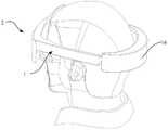
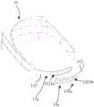
图1为本发明头戴式电子设备佩戴于头上时的使用状态图;Fig. 1 is the use state diagram when the head-mounted electronic device of the present invention is worn on the head;
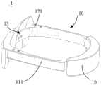
图2为图1中头戴式电子设备一实施例的结构示意图;FIG. 2 is a schematic structural diagram of an embodiment of the head-mounted electronic device in FIG. 1;
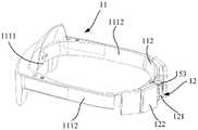
图3为图2的部分结构示意图;Fig. 3 is the partial structure schematic diagram of Fig. 2;
图4为本发明头戴式电子设备的头箍的控制结构框图;4 is a block diagram of the control structure of the headband of the head-mounted electronic device of the present invention;
图5为图3中驱动机构及调节结构的结构分解图;Fig. 5 is the structural exploded view of the drive mechanism and the adjustment structure in Fig. 3;
图6为图3部分结构的结构分解图;Fig. 6 is the structural exploded view of the partial structure of Fig. 3;
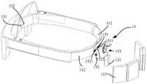
图7为图6中主体和调节结构的结构分解图;Fig. 7 is the structural exploded view of the main body and the adjustment structure in Fig. 6;
图8为容置于图6中主体内主控板、显示系统、柔性电路板的结构示意图;8 is a schematic structural diagram of a main control board, a display system, and a flexible circuit board accommodated in the main body in FIG. 6;
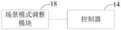
图9为本发明头戴式电子设备头箍的场景模式调整模块与控制器的控制结构框图;9 is a block diagram of the control structure of the scene mode adjustment module and the controller of the headband of the head-mounted electronic device of the present invention;
图10为本发明头戴式电子设备头箍的指令采集模块与控制器的控制结构框图。10 is a block diagram of the control structure of the command acquisition module and the controller of the headband of the head-mounted electronic device of the present invention.
附图标记说明如下:The reference numerals are explained as follows:
1、头箍;1. headband;
11、主体;主体11a;111主支架;112、调节支架;1111、前支架;1112、侧支架;11. main body;
12、驱动机构;121、驱动电机;122、电源;12, drive mechanism; 121, drive motor; 122, power supply;
13、检测组件;131、压力传感器;132、接近传感器;13. Detection component; 131. Pressure sensor; 132. Proximity sensor;
14控制器;14 controllers;
15、调节结构;151、调节件;1511、卡持部;151a、齿轮;152、调节部;1521、调节通孔;1521a、第一调节通孔;1521b、第二调节通孔;1522、配合部;1522a、齿牙;153、变速机构;1531、第一齿轮件;1532、第二齿轮件;15. Adjustment structure; 151, Adjustment member; 1511, Hold part; 151a, Gear; 152, Adjustment part; 1521, Adjustment through hole; 1521a, First adjustment through hole; 1521b, Second adjustment through hole; 1522,
16、活动壳体;16. Active shell;
17、指令采集模块;171、松紧控制按钮;172、触控件;173、角速度传感器;18额头挡板;17. Command acquisition module; 171. Elastic control button; 172. Touch control element; 173. Angular velocity sensor; 18. Forehead baffle;
2、头戴式电子设备;241主控板、242显示系统;243柔性电路板。2. Head mounted electronic equipment; 241 main control board, 242 display system; 243 flexible circuit board.
具体实施方式Detailed ways
尽管本发明可以容易地表现为不同形式的实施方式,但在附图中示出并且在本说明书中将详细说明的仅仅是其中一些具体实施方式,同时可以理解的是本说明书应视为是本公开原理的示范性说明,而并非旨在将本发明限制到在此所说明的那样。While the present invention may readily be embodied in different forms, only some of the specific embodiments are shown in the drawings and will be described in detail in this specification, while it is to be understood that this specification is to be regarded as the Exemplary illustrations of principles are disclosed and are not intended to limit the invention to those described herein.
由此,本说明书中所指出的一个特征将用于说明本公开的一个实施方式的其中一个特征,而不是暗示本发明的每个实施方式必须具有所说明的特征。此外,应当注意的是本说明书描述了许多特征。尽管某些特征可以组合在一起以示出可能的系统设计,但是这些特征也可用于其他的未明确说明的组合。由此,除非另有说明,所说明的组合并非旨在限制。Thus, a reference to a feature in this specification will be used to describe one of the features of an embodiment of the present disclosure and not to imply that every embodiment of the invention must have the described feature. Furthermore, it should be noted that this specification describes a number of features. Although certain features may be combined together to illustrate possible system designs, these features may also be used in other combinations not explicitly stated. Thus, unless otherwise stated, the combinations described are not intended to be limiting.
在附图所示的实施方式中,方向的指示(诸如上、下、左、右、前和后)用于解释本发明的各种元件的结构和运动不是绝对的而是相对的。当这些元件处于附图所示的位置时,这些说明是合适的。如果这些元件的位置的说明发生改变时,则这些方向的指示也相应地改变。In the embodiments shown in the drawings, directional indications (such as up, down, left, right, front and rear) are used to explain the structure and movement of the various elements of the invention not absolute but relative. These descriptions are appropriate when the elements are in the positions shown in the drawings. If the description of the positions of these elements changes, the indications of these directions change accordingly.
现在将参考附图更全面地描述示例实施方式。然而,示例实施方式能够以多种形式实施,且不应被理解为限于在此阐述的范例;相反,提供这些示例实施方式使得本公开的描述将更加全面和完整,并将示例实施方式的构思全面地传达给本领域的技术人员。附图仅为本公开的示意性图解,并非一定是按比例绘制。图中相同的附图标记表示相同或类似的部分,因而将省略对它们的重复描述。Example embodiments will now be described more fully with reference to the accompanying drawings. Example embodiments, however, can be embodied in various forms and should not be construed as limited to the examples set forth herein; rather, these example embodiments are provided so that this description of the present disclosure will be thorough and complete, and will consolidate the concept of the example embodiments. It will be fully conveyed to those skilled in the art. The drawings are merely schematic illustrations of the present disclosure and are not necessarily drawn to scale. The same reference numerals in the drawings denote the same or similar parts, and thus their repeated descriptions will be omitted.
以下结合本说明书的附图,对本发明的较佳实施方式予以进一步地详尽阐述。The preferred embodiments of the present invention will be further elaborated below with reference to the accompanying drawings of the present specification.
请参见图1和图2,本申请公开一种头戴式电子设备的头箍1,用于头戴式电子设备2,头戴式电子设备2可以是VR(Virtual Reality)、AR(Augmented Reality)或耳机等。请参见图3和图4;具体的,本申请实施例的头戴式电子设备的头箍1包括主体11、驱动机构12、检测组件13以及控制器14。主体11的两端11a通过调节结构15连接形成环形的头戴部;驱动机构12与调节结构15驱动连接,调节结构15带动主体11的两端11a相对运动,以调节头戴部的周向尺寸;检测组件13设于主体11上,检测组件13用于检测头戴部上的压力,并将检测结果输出至控制器14;控制器14与检测组件13以及驱动机构12均电性连接,检测组件13将检测结果输出至控制器14,当压力值大于阈值时,控制器14控制驱动结构停止工作。Please refer to FIG. 1 and FIG. 2. The present application discloses a headband 1 for a head-mounted electronic device, which is used for the head-mounted electronic device 2. The head-mounted electronic device 2 may be VR (Virtual Reality), AR (Augmented Reality) ) or headphones, etc. Please refer to FIG. 3 and FIG. 4 ; specifically, the headband 1 of the head-mounted electronic device according to the embodiment of the present application includes a
当用户佩戴本申请实施例中的头戴式电子设备的头箍1时,先将头箍1套在头上,检测装置开始检测头戴部上的压力,并将检测结果传输至控制器14。可以理解的是,当头戴部的周向尺寸较大时,用户的头部对头戴部的挤压力较小;而当头戴部的周向尺寸较小时,用户的头部对头戴部的挤压力较大。由力的相互作用性可知,用户头部所受到头箍1的压力与头箍1受到用户头部的挤压力相等;因此通过对头戴部上的压力进行检测,能够有效地判断用户头部所受到的压力,进而可以判断用户的佩戴舒适程度。When the user wears the headband 1 of the head-mounted electronic device in the embodiment of the present application, the headband 1 is first put on the head, and the detection device starts to detect the pressure on the head-mounted part, and transmits the detection result to the
请参见图4至图7,当控制器14根据检测装置的检测结果判断头戴部上的压力较大,控制器14输出一控制信号至驱动机构12,驱动机构12进而通过调节结构15使主体11两端朝远离对方的一侧移动,以使头戴部的周向尺寸增大。检测组件13随之进一步检测头戴部上的压力,直到头戴部上的压力在预设的压力区间内时,此时控制器14控制驱动机构12停止工作,以使主体11的两端11a保持在当前的位置,此时头戴部的尺寸使得用户感到较为舒适。Referring to FIGS. 4 to 7 , when the
具体的,控制器14控制驱动机构12运动,当压力传感器131检测的压力值满足预设阈值时,控制器14控制驱动结构停止工作。该预设阈值可以根据预先根据用户佩戴舒适时,采集的头戴部压力值进行设定。需要说明的是,该预设阈值可以是预设舒适阈值,或预设舒适区间。检测装置检测到的压力值满足预设阈值时,此时的松紧程度对于用户来说较为适中,满足用户舒适感的需求。Specifically, the
同样的,当控制器14根据检测装置的检测结果判断头戴部的压力较小,或小于预设的压力区间的下限值时,控制器14输出一控制信号至驱动机构12,驱动机构12进而通过调节结构15使主体11两端朝靠近对方的一侧移动,以使头戴部的周向尺寸减小。检测组件13随之进一步检测头戴部上的压力,直到头戴部上的压力在预设的压力区间内时,此时控制器14控制驱动机构12停止工作,以使主体11的两端11a保持在当前的位置,此时头戴部的尺寸使得用户感到较为舒适。Similarly, when the
参阅图7,在此需要说明的是,主体11的两端11a通过调节结构15连接形成环形的头戴部,因此调节结构15能够起到连接主体11的两端11a的作用,进而通过驱动机构12驱动该调节结构15,使得调节结构15在连接主体11两端的同时,调整主体11两端的相对距离,从而实现调节头戴部尺寸的技术效果。Referring to FIG. 7 , it should be noted here that the two
本申请实施例通过调节结构15连接主体11两端11a以形成环形的头戴部,并利用驱动机构12驱动调节结构15,以使得主体11两端的相对距离可调节。本申请实施例进一步通过设置用于检测头戴部上的压力的检测组件13和控制器14,控制器14根据检测组件13的检测结果,控制驱动机构12工作带动主体11的两端11a相对运动,以调节头戴部的周向尺寸,由此本申请实施例所提出的头戴式电子设备2的头箍1能够实现自动感测用户佩戴该头箍1所受的压力,进而判断用户的佩戴舒适度,并进一步通过驱动机构12调节头戴部尺寸以适配于用户头部尺寸,由此实现自适应调节佩戴松紧度的技术目的,因此本申请实施例大大提高了用户调整头箍1佩戴松紧的便利性。In this embodiment of the present application, the two
请参见图5和图7,本申请实施例中,调节结构15包括调节件151以及设置于主体11的两端11a的调节部152;调节件151与调节部152连接,驱动机构12通过控制调节件151运动,以带动主体11的两端11a相对移动。主体11大致呈环形,且具有两端部,本申请实施例中,调节部152可以仅设置在主体11的一个端部上,也可以同时设置主体11的两个端部上。可选的,调节部152位于主体11的两个端部上,通过调节部152、调节件151以及驱动机构12的结构和连接关系的设置,调节件151与该调节部152可以是滑动连接、固定连接等方式。Referring to FIGS. 5 and 7 , in the embodiment of the present application, the
本申请实施例中的主体11可以一体成型设置,也可以分段设置,在本申请实施例中,主体11包括主支架111以及与主支架111连接的调节支架112;主支架111的端部分别与一调节支架112的一端连接,因此此时调节结构15是设置于调节支架112与驱动机构12之间。并且,本申请头戴式电子设备2的头箍1的头箍1还包括活动壳体16,该活动壳体16用于容置调节支架112以及驱动机构12。当头箍1佩戴于用户头上时,该活动壳体16大致位于用户后脑勺位置。在以下实施例中,设置于主体11端部的结构均可以替换为设置于调节支架112上。The
在一实施例中,调节部152包括开设在主体11端部的通孔,调节件151为可伸缩的伸缩杆,两主体11端部的调节部152通过伸缩杆连接。驱动机构12与伸缩杆的可伸缩端连接,以驱动伸缩杆的拉伸或压缩,从而实现调节两主体11端部之间相对位置的目的。In one embodiment, the adjusting
在本申请实施例中,调节部152包括开设于主体11端部的调节通孔1521,调节通孔1521沿头戴部的周向延伸;调节件151收容于调节通孔1521内,调节件151包括本体以及设置在本体上的卡持部1511,调节通孔1521内设有与卡持部1511适配的配合部1522;驱动机构12驱动调节件151运动,以通过卡持部1511与配合部1522的卡持,使调节件151沿调节通孔1521运动。In the embodiment of the present application, the
在一具体实施例中,主体11的两端11a分别为调节端和固定端,调节通孔1521开设于主体11调节端上,调节件151为沿该滑槽滑动的滑块,滑块与主体11的固定端固定连接,驱动机构12驱动滑块沿调节通孔1521滑动。因此在滑块滑动的过程中,滑块带动主体11的固定端和调节端的位置发生改变,从而达到调节头戴部尺寸的效果。In a specific embodiment, the two
请参见图5至图7,在本实施例中,调节部152包括开设于主体11端部的调节通孔1521,以及沿调节通孔1521的孔壁设置的齿牙1522a,齿牙1522a供齿轮151a啮合。调节通孔1521沿头戴部的周向延伸;齿轮151a收容于调节通孔1521内,驱动机构12驱动齿轮151a驱动转动,以改变主体11的两端11a相对位置。Referring to FIGS. 5 to 7 , in this embodiment, the adjusting
在一具体实施例中,当主体11的一端为调节端,该调节端上开设有调节通孔1521;主体11的另一端部为固定端,该固定端可以通过轴承固定在齿轮151a轴上,以在齿轮151a转动的时候,该固定端不跟随齿轮151a转动;齿轮151a通过与调节通孔1521孔壁上齿牙啮合1522a时,齿轮151a便可以带动固定端相对调节端发生位移,从而改变主体11调节端和固定端的相对位置,进而实现调整头戴部尺寸的目的。In a specific embodiment, when one end of the
在本实施例中,主体11的两端11a均具有调节通孔1521,且两调节通孔1521连通;一调节通孔1521的孔壁顶面设有齿牙1522a,另一调节通孔1521的孔壁底面设有齿牙1522a;齿轮151a依次穿过两调节通孔1521,且与两调节通孔1521上的齿牙1522a均啮合。In this embodiment, both ends 11a of the
具体的,主体11包括主支架111以及与主支架111连接的调节支架112;主支架111的两端分别与两调节支架112的一端连接,调节通孔1521设置于调节支架112上。调节通孔1521大致呈腰形。Specifically, the
主体11的两端11a端部分别开设有第一调节通孔1521a及第二调节通孔1521b,主体11的两端11a端部相互重叠,且第一调节通孔1521a与第二调节通孔1521b相对连通,齿轮151a同时收容于第一调节通孔1521a与第二调节通孔1521b内;第一调节通孔1521a的内孔壁的顶面设有上齿牙1522a,第二调节通孔1521b的内孔壁的底面设有下齿牙1522a,齿轮151a的上下两侧面分别与上齿牙1522a与下齿牙1522a相啮合。齿轮151a通过转动以使两调节支架112沿头戴部的周向方向发生相对位移,从而达到调整头戴部周向尺寸的效果。The ends of the two
可以理解的是,此时主体11的两端11a一方面通过齿轮151a实现连接,另一方面也是通过齿轮151a实现相对距离的调整。具体的,齿轮151a顺时针转动时,齿轮151a带动主体11两端部朝靠近对方的一侧运动,从而减小头戴部的周向尺寸。而齿轮151a逆时针转动时,齿轮151a带动主体11两端部朝远离对方的一侧运动,从而增大头戴部的周向尺寸。It can be understood that, at this time, the two
本实施例中,驱动机构12包括驱动电机121以及为驱动电机121供电的电源122;驱动电机121驱动齿轮151a转动。驱动电机121具有驱动轴,该驱动轴可以与齿轮151a直接连接或通过变速机构153通过联动轴连接,或者电机的驱动轴直接穿过齿轮151a的中心,以作为齿轮151a的转轴。In this embodiment, the
在另一实施例中,驱动机构12通过气动方式以驱动调节结构15运动,驱动该机构包括小型气泵,以及可通过充气延展伸缩的伸缩件,伸缩件的两端对应与主体11的两端11a连接,此时伸缩件作为调节结构15,通过对伸缩件进行充气,使得其长度增大,从而增大头戴部的周向尺寸。In another embodiment, the
当通过驱动电机121驱动齿轮151a转动时,为了调节驱动电机121的转速,以及增大扭矩,本申请实施例中,设置驱动机构12还包括变速机构153,变速机构153包括第一齿轮件1531和第二齿轮件1532;第一齿轮件1531与调节结构15驱动连接,第二齿轮件1532与驱动机构12驱动连接。When the
进一步的,本方案实施例的头箍1还包括活动壳体16,驱动机构12容置于活动壳体16内,为了合理利用活动壳体16内的空间,本方案设置第一齿轮件1531和第二齿轮件1532均为锥形齿轮,以使第一齿轮件1531和第二齿轮件1532呈夹角设置。可选的,第一齿轮件1531和第二齿轮件1532大致呈90°。Further, the headband 1 of the embodiment of this scheme also includes a
进一步的,本实施例的电机的长度方向沿头箍1的高度方向延伸,上述电源122为电池,电池有多个,多个电池沿头箍1的周向方向对称分布于电机两侧。Further, the length direction of the motor in this embodiment extends along the height direction of the headband 1 , the
在此以头箍1正常被佩戴使用时的方位为参照,用户脸的朝向为前侧,用户额头的朝向为后侧。本方案中主体11包括主支架111,活动支架,活动支架至少部分收容于活动壳体16内。主支架111包括前支架1111,以及分别连接于前支架1111两端的两侧支架1112,侧支架1112位于前支架1111的后侧。在以下实施例中,可以基于本段中主体11结构的实施例为参照,对以下关于检测装置和控制器14的实施例进行说明。Here, the orientation of the headband 1 when it is normally worn and used is used as a reference, the orientation of the user's face is the front side, and the orientation of the user's forehead is the rear side. In this solution, the
请参见图5和图6,在本方案实施例中,检测组件13包括压力传感器131;压力传感器131设于主体11上,且至少有一个。压力传感器131的设置位置需要靠近头箍1用于贴合用户头部的一侧,以提高检测压力的准确性。Referring to FIG. 5 and FIG. 6 , in the embodiment of this solution, the
在本申请一具体实施例中,压力传感器131有两个,分别设于前支架1111上和活动支架上。因此两压力传感器131分别对应检测用户前额处的压力以及后脑勺处所受到的压力。控制器14通过两个压力传感器131同时对用户佩戴头箍1时的松紧程度进行检测。In a specific embodiment of the present application, there are two
具体的,压力传感器131与控制器14电连接;控制器14控制驱动机构12运动,直到压力传感器131检测的压力值满足预设舒适条件。需要说明的是,该预设舒适条件可以是预设舒适阈值,或预设舒适区间。压力传感器131检测到的压力值满足预设舒适条件时,此时的松紧程度对于用户来说较为适中,满足用户舒适感的需求。Specifically, the
请参见图9,进一步的,考虑到用户在不同的使用场景下,对佩戴头箍1的松紧度具有不同的要求,本申请实施例中设置控制器14对应多种场景模式设有多个阈值;主体11上设有供用户选择场景模式的场景模式调整模块,场景模式调整模块与控制器14电连接,场景模式调整模块包括多种场景模式,控制器14根据场景模式调整模块选取的场景模式选取相应的阈值。Referring to FIG. 9, further, considering that the user has different requirements for the tightness of wearing the headband 1 under different usage scenarios, in the embodiment of the present application, the
例如用户看电影时,需要较松的佩戴松紧度,因此可以设置较低的预设舒适阈值或较低的预设舒适区间。然而当用户在运动时,需要较紧的佩戴松紧度,因此可以设置较高的预设舒适阈值或较高的预设舒适区间。For example, when a user is watching a movie, a looser wearing tightness is required, so a lower preset comfort threshold or a lower preset comfort zone can be set. However, when the user is exercising, a tighter wearing tightness is required, so a higher preset comfort threshold or a higher preset comfort zone can be set.
可以通过在主体11上设置拨动开关或通过软件,供用户自行调节使用场景模式,控制器14根据用户选择的使用场景匹配预设的舒适条件,用以控制驱动机构12工作。使用场景可以为观影模式、跑步模式、散步模式等,在此不做限定。A toggle switch can be provided on the
进一步的,为了防止用户的手按压头箍1上的压力传感器131,而造成驱动机构12误动作,本方案实施例中,进一步设置检测组件13包括接近传感器132;接近传感器132设于主体11上,且至少有一个,控制器14根据压力传感器131和接近传感器132的检测结果,控制驱动机构12工作。Further, in order to prevent the user's hand from pressing the
接近传感器132可以设置于前支架1111上。接近传感器132无需接触检测对象即可以进行检测有无物体靠近,并能检测对象的移动信息和存在信息转换为电气信号。接近传感器132可以是通过电气信号的容量变化的方式、利石和引导开关的方式等,在此不做限定。The
在另一实施例中,头箍1还包括设置于主支架111一侧的额头挡板18,当用户佩戴头箍1时,额头挡18板与用户前额抵持。压力传感器131、接近传感器132可以设置于额头挡板18上。In another embodiment, the headband 1 further includes a
请参见图10,进一步的,为了便于用户根据自己的需求,以自行控制控制头箍1开始调节尺寸,本申请实施例中,头戴式电子设备2的头箍1还具有指令采集模块17,指令采集模块17与控制器14电连接,指令采集模块17用于采集控制指令。控制器14根据控制指令生成调节信号,并根据调节信号控制驱动机构12工作。Please refer to FIG. 10, further, in order to facilitate the user to control the headband 1 to adjust the size according to his own needs, in the embodiment of the present application, the headband 1 of the head-mounted electronic device 2 also has an
在一实施例中,指令采集模块17包括松紧控制按钮171;松紧控制按钮171设于主体11上;松紧控制按钮171用于接收按压操作的控制指令;控制器14根据松紧控制按钮171接收到的按压或旋转操作,生成调节信号。例如,当用户按下按钮时,此时压力传感器131、驱动机构12开始工作,以协同对头戴部的周向尺寸进行调节。按钮可以设置在侧支架1112上,以便于用户操作。In one embodiment, the
在又一实施例中,指令采集模块17包括用于接收触控操作的触控件172,触控件172设于主体11上;控制器14根据触控件172接收到的触控操作,生成调节信号。触控件172可以是设置在主体11上的触控平面,可选的,该触控平面设置在侧支架1112上。用户通过手在触控平面上按照规定进行操作,控制器14识别该操作是否为预设操作,当满足条件时,控制器14生成调节信号;压力传感器131、驱动机构12开始工作,以协同对头戴部的周向尺寸进行调节。In yet another embodiment, the
在又一实施例中,指令采集模块17包括摄像组件,摄像组件设于主体11上,摄像组件用于拍摄控制手势;控制器14根据摄像组件拍摄的控制手势生成调节信号。当用户在摄像头的拍摄区域按照规定发出规定手势时,控制器14识别该手势是否为预设手势;当满足条件时,控制器14生成调节信号,压力传感器131、驱动机构12开始工作,以协同对头戴部的周向尺寸进行调节。In yet another embodiment, the
在又一实施例中,指令采集模块17包括角速度传感器173,角速度传感器173设于主体11或头托上;角速度传感器173用于检测佩戴动作的角速度。控制器14根据角速度传感器173检测到的佩戴动作生成调节信号。In yet another embodiment, the
该角速度传感器173可以为陀螺仪。用户在佩戴该头戴式设备的时,其佩戴动作会被陀螺仪检测到,从而控制器14识别该动作是否为预设动作,当满足条件时,控制器14生成调节信号,压力传感器131、驱动机构12开始工作,以协同对头戴部的周向尺寸进行调节。The
以下为本申请头戴式电子设备2的头箍1完整工作过程的实施例。The following is an example of a complete working process of the headband 1 of the head-mounted electronic device 2 of the present application.
当用户戴上需要头戴式电子设备2时,通过按下头箍1上的松紧控制按钮171,此时头箍1上接近传感器132判断有物体接近,以及前支架1111上的压力传感器131判断为有受压的情况下,控制器14控制驱动电机121开始转动,驱动电机121通过变速机构153驱动齿轮151a顺时针转动,以带动两活动支架发生相对运动,从而使得整个头戴部的周向尺寸减小以收紧。在尺寸调节过程中,由前支架1111和活动支架上的压力传感器131同时判断,当其中一个传感器检测到的压力值满足预设舒适区间时(预估在100g-5kg左右的力),电机停止转动,完成松紧调节过程。电机自带停机自锁功能,此为头戴设备头箍1的尺寸使用户感到舒适。When the user wears the required head-mounted electronic device 2, by pressing the
当用户想取下头戴设备时,通过按下松紧控制按钮171,由控制器14通过获取位于前支架1111上和活动支架上的压力传感器131的检测值,当其中任一个压力传感器131的压力值位于预设舒适区间内时,且接近传感器132判断有物体接近的情况下,此时控制器14判断该头戴设备处于佩戴状态,现在需要进行取下操作。然后,控制器14控制电机向反方向转动,通过变速机构153以带动齿轮151a逆时针转动,以带动两活动支架发生相对运动,从而使得整个头戴部的周向尺寸增大以放宽,直到用户取下该头戴设备。在在增大头箍1周向尺寸的实现方式中,也可以通过控制器14控制齿轮151a转动预设圈数,使头戴部的周向尺寸增大预设长度(30mm-80mm左右),以供用户取下该头戴设备。When the user wants to take off the headset, by pressing the
本申请实施例还包括一种头戴式电子设备2,请参阅图1和图2,头戴式电子设备2包括上述实施例中的头戴式电子设备的头箍1。该头戴式电子设备2可以是VR、AR或头戴耳机。The embodiment of the present application further includes a head-mounted electronic device 2, please refer to FIG. 1 and FIG. 2, the head-mounted electronic device 2 includes the headband 1 of the head-mounted electronic device in the above embodiment. The headset 2 may be a VR, AR or headset.
在此以VR为例,请参阅图8,头戴式电子设备2还包括主控板241、显示系统242以及柔性电路板243。头箍1的前支架1111内具有容置腔,主控板241、显示系统242设于头箍1的容置腔内。柔性电路板243与主控板241电连接,且柔性电路板243可以穿设于侧支架1112与头箍1的驱动电机121和电池电连接。可选的,头戴式电子设备2的主控制器主控板21可代替上述头戴式电子设备2的头箍1中的控制器14。Taking VR as an example, please refer to FIG. 8 , the head-mounted electronic device 2 further includes a
虽然已参照几个典型实施方式描述了本发明,但应当理解,所用的术语是说明和示例性、而非限制性的术语。由于本发明能够以多种形式具体实施而不脱离发明的精神或实质,所以应当理解,上述实施方式不限于任何前述的细节,而应在随附权利要求所限定的精神和范围内广泛地解释,因此落入权利要求或其等效范围内的全部变化和改型都应为随附权利要求所涵盖。While the present invention has been described with reference to several exemplary embodiments, it is to be understood that the terminology used is of description and illustration, and not of limitation. Since the invention can be embodied in many forms without departing from the spirit or spirit of the invention, it is to be understood that the above-described embodiments are not limited to any of the foregoing details, but are to be construed broadly within the spirit and scope defined by the appended claims Therefore, all changes and modifications that come within the scope of the claims or their equivalents should be covered by the appended claims.
Claims (17)
Priority Applications (1)
| Application Number | Priority Date | Filing Date | Title |
|---|---|---|---|
| CN201910517738.8ACN112083574A (en) | 2019-06-14 | 2019-06-14 | Head band of head-mounted electronic equipment and head-mounted electronic equipment |
Applications Claiming Priority (1)
| Application Number | Priority Date | Filing Date | Title |
|---|---|---|---|
| CN201910517738.8ACN112083574A (en) | 2019-06-14 | 2019-06-14 | Head band of head-mounted electronic equipment and head-mounted electronic equipment |
Publications (1)
| Publication Number | Publication Date |
|---|---|
| CN112083574Atrue CN112083574A (en) | 2020-12-15 |
Family
ID=73734195
Family Applications (1)
| Application Number | Title | Priority Date | Filing Date |
|---|---|---|---|
| CN201910517738.8APendingCN112083574A (en) | 2019-06-14 | 2019-06-14 | Head band of head-mounted electronic equipment and head-mounted electronic equipment |
Country Status (1)
| Country | Link |
|---|---|
| CN (1) | CN112083574A (en) |
Cited By (15)
| Publication number | Priority date | Publication date | Assignee | Title |
|---|---|---|---|---|
| CN113031282A (en)* | 2021-04-27 | 2021-06-25 | 歌尔股份有限公司 | Method for adjusting size of binding band of head-mounted display equipment and related device |
| CN113171100A (en)* | 2021-04-20 | 2021-07-27 | Oppo广东移动通信有限公司 | Wearables |
| CN113419346A (en)* | 2021-05-31 | 2021-09-21 | 潍坊歌尔电子有限公司 | Head-mounted adjusting device and head-mounted display equipment |
| CN113566100A (en)* | 2021-07-26 | 2021-10-29 | 歌尔光学科技有限公司 | Wearables and Smart Devices |
| CN114690430A (en)* | 2022-04-21 | 2022-07-01 | 盈拓国际展览有限公司 | Online and offline combined VR exhibition display device, system and display method |
| CN114690425A (en)* | 2022-03-30 | 2022-07-01 | 歌尔智能科技有限公司 | Intelligent head-mounted equipment |
| CN115128834A (en)* | 2022-06-06 | 2022-09-30 | 杭州回车电子科技有限公司 | Glasses-shaped biological signal acquisition device and adjustment method |
| CN115469692A (en)* | 2022-08-15 | 2022-12-13 | 联想(北京)有限公司 | Control method and wearable device |
| WO2023277322A1 (en)* | 2021-07-01 | 2023-01-05 | 주식회사 피앤씨솔루션 | Head mounted display device automatically resized by using ultra-precision motor and distance measuring sensor |
| CN115685559A (en)* | 2022-11-07 | 2023-02-03 | 歌尔科技有限公司 | Adaptive wearing method of VR equipment, electronic equipment and readable storage medium |
| CN115826174A (en)* | 2022-11-29 | 2023-03-21 | 西安交通大学 | Packaging device and method based on coupling of prism and whispering gallery mode resonant cavity |
| CN115954791A (en)* | 2022-11-15 | 2023-04-11 | 国网北京市电力公司 | Portable electric power inspection auxiliary device |
| CN116540408A (en)* | 2023-04-03 | 2023-08-04 | 深圳市欢创互动科技有限公司 | Head-mounted device, its tightness adjustment method and its adjustment device |
| CN116718267A (en)* | 2023-08-08 | 2023-09-08 | 四川京炜交通工程技术有限公司 | Mobile traffic technology monitoring imaging stroboscopic light-supplementing lamp illuminance measurement method |
| CN117130167A (en)* | 2023-10-27 | 2023-11-28 | 玩出梦想(上海)科技有限公司 | Head-mounted device and its wearing adaptive adjustment method |
Citations (6)
| Publication number | Priority date | Publication date | Assignee | Title |
|---|---|---|---|---|
| CN106641667A (en)* | 2016-11-29 | 2017-05-10 | 维沃移动通信有限公司 | Control method for virtual reality equipment and virtual reality equipment |
| CN106773037A (en)* | 2016-11-30 | 2017-05-31 | 珠海市魅族科技有限公司 | A kind of method and virtual reality device for adjusting virtual reality device |
| CN208013552U (en)* | 2018-01-31 | 2018-10-26 | 歌尔科技有限公司 | Wear display equipment |
| CN108769850A (en)* | 2018-05-22 | 2018-11-06 | Oppo广东移动通信有限公司 | Device control method and related products |
| CN208384248U (en)* | 2018-07-13 | 2019-01-15 | 深圳创维新世界科技有限公司 | It wears and wear-type virtual reality shows equipment |
| CN109480806A (en)* | 2018-09-19 | 2019-03-19 | 歌尔科技有限公司 | The adjusting method of helmet and its object wearing device and helmet |
- 2019
- 2019-06-14CNCN201910517738.8Apatent/CN112083574A/enactivePending
Patent Citations (6)
| Publication number | Priority date | Publication date | Assignee | Title |
|---|---|---|---|---|
| CN106641667A (en)* | 2016-11-29 | 2017-05-10 | 维沃移动通信有限公司 | Control method for virtual reality equipment and virtual reality equipment |
| CN106773037A (en)* | 2016-11-30 | 2017-05-31 | 珠海市魅族科技有限公司 | A kind of method and virtual reality device for adjusting virtual reality device |
| CN208013552U (en)* | 2018-01-31 | 2018-10-26 | 歌尔科技有限公司 | Wear display equipment |
| CN108769850A (en)* | 2018-05-22 | 2018-11-06 | Oppo广东移动通信有限公司 | Device control method and related products |
| CN208384248U (en)* | 2018-07-13 | 2019-01-15 | 深圳创维新世界科技有限公司 | It wears and wear-type virtual reality shows equipment |
| CN109480806A (en)* | 2018-09-19 | 2019-03-19 | 歌尔科技有限公司 | The adjusting method of helmet and its object wearing device and helmet |
Cited By (24)
| Publication number | Priority date | Publication date | Assignee | Title |
|---|---|---|---|---|
| CN113171100A (en)* | 2021-04-20 | 2021-07-27 | Oppo广东移动通信有限公司 | Wearables |
| CN113031282A (en)* | 2021-04-27 | 2021-06-25 | 歌尔股份有限公司 | Method for adjusting size of binding band of head-mounted display equipment and related device |
| CN113419346A (en)* | 2021-05-31 | 2021-09-21 | 潍坊歌尔电子有限公司 | Head-mounted adjusting device and head-mounted display equipment |
| WO2023277322A1 (en)* | 2021-07-01 | 2023-01-05 | 주식회사 피앤씨솔루션 | Head mounted display device automatically resized by using ultra-precision motor and distance measuring sensor |
| KR102619431B1 (en) | 2021-07-01 | 2024-01-02 | 주식회사 피앤씨솔루션 | Head-mounted display apparatus that automatically adjusts its size using motor and distance measuring sensor |
| KR20230005701A (en)* | 2021-07-01 | 2023-01-10 | 주식회사 피앤씨솔루션 | Head-mounted display apparatus that automatically adjusts its size using motor and distance measuring sensor |
| WO2023005792A1 (en)* | 2021-07-26 | 2023-02-02 | 歌尔股份有限公司 | Wearable device and intelligent device |
| CN113566100B (en)* | 2021-07-26 | 2023-08-08 | 歌尔科技有限公司 | Wearing equipment and intelligent device |
| CN113566100A (en)* | 2021-07-26 | 2021-10-29 | 歌尔光学科技有限公司 | Wearables and Smart Devices |
| CN114690425A (en)* | 2022-03-30 | 2022-07-01 | 歌尔智能科技有限公司 | Intelligent head-mounted equipment |
| CN114690430B (en)* | 2022-04-21 | 2024-05-07 | 盈拓国际展览有限公司 | Online and offline combined VR exhibition display device, system and display method |
| CN114690430A (en)* | 2022-04-21 | 2022-07-01 | 盈拓国际展览有限公司 | Online and offline combined VR exhibition display device, system and display method |
| CN115128834A (en)* | 2022-06-06 | 2022-09-30 | 杭州回车电子科技有限公司 | Glasses-shaped biological signal acquisition device and adjustment method |
| CN115469692A (en)* | 2022-08-15 | 2022-12-13 | 联想(北京)有限公司 | Control method and wearable device |
| CN115685559A (en)* | 2022-11-07 | 2023-02-03 | 歌尔科技有限公司 | Adaptive wearing method of VR equipment, electronic equipment and readable storage medium |
| CN115954791A (en)* | 2022-11-15 | 2023-04-11 | 国网北京市电力公司 | Portable electric power inspection auxiliary device |
| CN115954791B (en)* | 2022-11-15 | 2024-01-30 | 国网北京市电力公司 | A portable power inspection auxiliary device |
| CN115826174A (en)* | 2022-11-29 | 2023-03-21 | 西安交通大学 | Packaging device and method based on coupling of prism and whispering gallery mode resonant cavity |
| CN115826174B (en)* | 2022-11-29 | 2024-08-16 | 西安交通大学 | A packaging device and method based on prism and whispering gallery mode resonant cavity coupling |
| CN116540408A (en)* | 2023-04-03 | 2023-08-04 | 深圳市欢创互动科技有限公司 | Head-mounted device, its tightness adjustment method and its adjustment device |
| CN116718267B (en)* | 2023-08-08 | 2023-10-31 | 四川京炜交通工程技术有限公司 | Mobile traffic technology monitoring imaging stroboscopic light-supplementing lamp illuminance measurement method |
| CN116718267A (en)* | 2023-08-08 | 2023-09-08 | 四川京炜交通工程技术有限公司 | Mobile traffic technology monitoring imaging stroboscopic light-supplementing lamp illuminance measurement method |
| CN117130167A (en)* | 2023-10-27 | 2023-11-28 | 玩出梦想(上海)科技有限公司 | Head-mounted device and its wearing adaptive adjustment method |
| CN117130167B (en)* | 2023-10-27 | 2024-01-02 | 玩出梦想(上海)科技有限公司 | Head-mounted device and its wearing adaptive adjustment method |
Similar Documents
| Publication | Publication Date | Title |
|---|---|---|
| CN112083574A (en) | Head band of head-mounted electronic equipment and head-mounted electronic equipment | |
| US11668958B2 (en) | Modular wearable electronic devices, systems, and methods | |
| CN208953789U (en) | Display is installed by the head that user wears | |
| TWI539810B (en) | Panoramic scene capturing and browsing mobile device, system and method | |
| CN209014814U (en) | Display is installed by the head that user wears | |
| CN109480806A (en) | The adjusting method of helmet and its object wearing device and helmet | |
| US20160004085A1 (en) | Head-mounted display device with air conditioning device and control approaches | |
| CN212933144U (en) | VR helmet all-in-one of intelligent regulation elasticity | |
| US11435655B2 (en) | Gyro sensor or virtual joystick controlled smart helmet | |
| WO2017113487A1 (en) | Head-mounted device | |
| CN106256135A (en) | Wear-type electronic installation | |
| WO2018152850A1 (en) | Head-mounted display device and adjustment method therefor | |
| JP5186723B2 (en) | Communication robot system and communication robot gaze control method | |
| EP3944842A1 (en) | Smart welding helmet modules with adaptable helmet devices | |
| CN112946886B (en) | Head-mounted device bracket and head-mounted device | |
| KR20130059827A (en) | Glasses type camera using by pupil tracker | |
| WO2018157422A1 (en) | Video glasses head hoop and video glasses | |
| CN208657037U (en) | The universal type of micro-control adjustable head carried chucking power wears bluetooth headset | |
| KR20170084443A (en) | Method for controlling head mount display device | |
| US9298010B2 (en) | Wearable optical display with audio functionality | |
| CN220252539U (en) | Automatic telescopic headband and control device thereof | |
| CN117741980A (en) | Intelligent strap adjusting system, method, head-mounted display device and storage medium | |
| KR20150004097U (en) | Apparatus for attaching a camera to a helmet | |
| CN112083796A (en) | Control method, head-mounted device, mobile terminal and control system | |
| US20220413306A1 (en) | Gyro sensor or virtual joystick controlled smart helmet |
Legal Events
| Date | Code | Title | Description |
|---|---|---|---|
| PB01 | Publication | ||
| PB01 | Publication | ||
| SE01 | Entry into force of request for substantive examination | ||
| SE01 | Entry into force of request for substantive examination | ||
| RJ01 | Rejection of invention patent application after publication | ||
| RJ01 | Rejection of invention patent application after publication | Application publication date:20201215 |