CN112081560A - A method for developing deep offshore high temperature and overpressure gas reservoirs - Google Patents
A method for developing deep offshore high temperature and overpressure gas reservoirsDownload PDFInfo
- Publication number
- CN112081560A CN112081560ACN202010903572.6ACN202010903572ACN112081560ACN 112081560 ACN112081560 ACN 112081560ACN 202010903572 ACN202010903572 ACN 202010903572ACN 112081560 ACN112081560 ACN 112081560A
- Authority
- CN
- China
- Prior art keywords
- water
- gas
- pressure
- core
- intermediate container
- Prior art date
- Legal status (The legal status is an assumption and is not a legal conclusion. Google has not performed a legal analysis and makes no representation as to the accuracy of the status listed.)
- Granted
Links
Images

Classifications
- E—FIXED CONSTRUCTIONS
- E21—EARTH OR ROCK DRILLING; MINING
- E21B—EARTH OR ROCK DRILLING; OBTAINING OIL, GAS, WATER, SOLUBLE OR MELTABLE MATERIALS OR A SLURRY OF MINERALS FROM WELLS
- E21B43/00—Methods or apparatus for obtaining oil, gas, water, soluble or meltable materials or a slurry of minerals from wells
- E21B43/01—Methods or apparatus for obtaining oil, gas, water, soluble or meltable materials or a slurry of minerals from wells specially adapted for obtaining from underwater installations
- E—FIXED CONSTRUCTIONS
- E21—EARTH OR ROCK DRILLING; MINING
- E21B—EARTH OR ROCK DRILLING; OBTAINING OIL, GAS, WATER, SOLUBLE OR MELTABLE MATERIALS OR A SLURRY OF MINERALS FROM WELLS
- E21B43/00—Methods or apparatus for obtaining oil, gas, water, soluble or meltable materials or a slurry of minerals from wells
- E21B43/16—Enhanced recovery methods for obtaining hydrocarbons
- E21B43/164—Injecting CO2 or carbonated water
- E—FIXED CONSTRUCTIONS
- E21—EARTH OR ROCK DRILLING; MINING
- E21B—EARTH OR ROCK DRILLING; OBTAINING OIL, GAS, WATER, SOLUBLE OR MELTABLE MATERIALS OR A SLURRY OF MINERALS FROM WELLS
- E21B43/00—Methods or apparatus for obtaining oil, gas, water, soluble or meltable materials or a slurry of minerals from wells
- E21B43/16—Enhanced recovery methods for obtaining hydrocarbons
- E21B43/20—Displacing by water
- E—FIXED CONSTRUCTIONS
- E21—EARTH OR ROCK DRILLING; MINING
- E21B—EARTH OR ROCK DRILLING; OBTAINING OIL, GAS, WATER, SOLUBLE OR MELTABLE MATERIALS OR A SLURRY OF MINERALS FROM WELLS
- E21B49/00—Testing the nature of borehole walls; Formation testing; Methods or apparatus for obtaining samples of soil or well fluids, specially adapted to earth drilling or wells
Landscapes
- Engineering & Computer Science (AREA)
- Mining & Mineral Resources (AREA)
- Geology (AREA)
- Life Sciences & Earth Sciences (AREA)
- Fluid Mechanics (AREA)
- Environmental & Geological Engineering (AREA)
- Physics & Mathematics (AREA)
- General Life Sciences & Earth Sciences (AREA)
- Geochemistry & Mineralogy (AREA)
- Chemical & Material Sciences (AREA)
- Chemical Kinetics & Catalysis (AREA)
- Investigating Strength Of Materials By Application Of Mechanical Stress (AREA)
- Filling Or Discharging Of Gas Storage Vessels (AREA)
Abstract
Translated fromChinese
Description
Translated fromChinese技术领域technical field
本发明属于天然气开发技术领域,尤其涉及一种海上深层高温超压气藏开发方法。The invention belongs to the technical field of natural gas development, and in particular relates to a development method for an offshore deep high temperature and overpressure gas reservoir.
背景技术Background technique
目前,异常高压气藏是指气藏压力高于静水压力,并且压力系数大于1.2的气藏。因异常高压气藏压力系数高,部分气藏压力系数甚至达到2.0以上,为了安全开发异常高压气藏,现有开采方法的生产井需采用多套管层序、高材质管材及采气设备,井口及地面设备安全等级也需大大提高,单井投资是常规井的3倍左右,大幅度增加了开发投资,使得部分异常高压天然气资源难以经济有效动用。由于(1)储层温度压力极高,还未有模拟如此高温高压条件进行物理模拟实验的相关研究;(2)天然气组分中高含CO2,还未有考虑气组分中CO2含量对微观渗流机理和宏观生产特征的影响;(3)该类气藏气井测试初期部分气井即产水,且生产过程中多口气井均不同程度的产水,导致水侵机理十分复杂,气井水源类型多样且来源不明,还未有针对水源识别进行相应模拟实验的研究,然而现有技术并没有针对海上深层海上深层高温超压气藏开发方法。At present, abnormally high-pressure gas reservoirs refer to gas reservoirs whose gas reservoir pressure is higher than hydrostatic pressure and whose pressure coefficient is greater than 1.2. Due to the high pressure coefficient of abnormally high-pressure gas reservoirs, the pressure coefficient of some gas reservoirs even reaches above 2.0. In order to safely develop abnormally high-pressure gas reservoirs, the production wells of the existing production methods need to use multi-casing sequences, high-quality pipes and gas production equipment. The safety level of wellhead and surface equipment also needs to be greatly improved. The investment in a single well is about three times that of a conventional well, which greatly increases the development investment, making it difficult for some abnormally high-pressure natural gas resources to be produced economically and effectively. Because (1) the temperature and pressure of the reservoir are extremely high, there is no relevant research on physical simulation experiments simulating such high temperature and high pressure conditions; (2) the natural gas component contains high CO2 , and the effect of the CO2 content in the gas component has not been considered. The influence of microscopic seepage mechanism and macroscopic production characteristics; (3) In the early stage of gas well testing in this type of gas reservoir, some gas wells produce water, and during the production process, many gas wells produce water to different degrees, resulting in a very complex water invasion mechanism, and the type of water source in gas wells. Diverse and unknown sources, there is no research on corresponding simulation experiments for water source identification. However, the existing technology does not target the development of deep offshore high temperature and overpressure gas reservoirs.
通过上述分析,现有技术存在的问题及缺陷为:现有技术并没有针对海上海上深层高温超压气藏开发方法。Through the above analysis, the existing problems and defects of the prior art are: the prior art does not aim at the development method of offshore deep high temperature and overpressure gas reservoirs.
解决以上问题及缺陷的难度为:The difficulty of solving the above problems and defects is as follows:
(1)深层油气藏储层埋藏深(>4500m),温度和压力条件极高,常规实验装置及实验方法难以完全模拟实际储层的温压条件,这会使得实验结果与实际情况存在差异。(1) Deep oil and gas reservoirs are buried deep (>4500m), and the temperature and pressure conditions are extremely high. It is difficult for conventional experimental devices and experimental methods to fully simulate the temperature and pressure conditions of the actual reservoir, which will make the experimental results different from the actual situation.
(2)深层油气藏储层含水饱和度和天然气组分中CO2含量差异大,导致该类气藏渗流机理十分复杂,模拟不同含水饱和度条件和不同CO2含量条件进行物理模拟实验研究难度较大。(2) The water saturation of deep oil and gas reservoirs and the CO2 content in the natural gas components are very different, which makes the seepage mechanism of this type of gas reservoir very complicated, and it is difficult to simulate the physical simulation experiments under different water saturation conditions and different CO2 content conditions. larger.
(3)深层高温超压气藏部分气井生产过程中见水特征差异大,见水机理不明确,且见水后对气井产能和采收率的影响难以确定,不同类型气井水源识别难度大。(3) The water breakthrough characteristics of some gas wells in deep high temperature and overpressure gas reservoirs vary greatly during the production process, the water breakthrough mechanism is not clear, and the impact on gas well productivity and recovery after water breakthrough is difficult to determine, and it is difficult to identify water sources for different types of gas wells.
(4)深层高温超压气藏长期气水同产会诱发复杂的水岩反应,且高含量的CO2会改变地层水的物理化学性质,评价储层见水后的多重伤害机理及其对气井产能的影响难度大。(4) Long-term co-production of gas and water in deep high-temperature and overpressure gas reservoirs will induce complex water-rock reactions, and high content of CO2 will change the physical and chemical properties of formation water. To evaluate the multiple damage mechanisms after reservoir water breakthrough and its impact on gas well productivity impact is difficult.
(5)针对该类气藏的高温、高压、低渗及含水饱和度和CO2含量差异大等特点,确定有效开发关键参数,并制定相应的高效开发技术政策和方案难度大。(5) In view of the characteristics of high temperature, high pressure, low permeability, and large differences in water saturation and CO2 content, it is difficult to determine the key parameters of effective development and formulate corresponding high-efficiency development technical policies and programs.
解决以上问题及缺陷的意义为:(1)从机理方面是揭示深层高温超压气藏的复杂渗流机理;(2)从应用方面是指导该类气藏的高效开发方案的制定。The significance of solving the above problems and defects is: (1) In terms of mechanism, it is to reveal the complex seepage mechanism of deep high temperature and overpressure gas reservoirs; (2) In terms of application, it is to guide the formulation of efficient development plans for such gas reservoirs.
发明内容SUMMARY OF THE INVENTION
针对现有技术存在的问题,本发明提供了一种海上深层高温超压气藏开发方法。Aiming at the problems existing in the prior art, the present invention provides a method for developing an offshore deep high temperature and overpressure gas reservoir.
本发明是这样实现的,一种海上深层高温超压气藏开发方法,所述海上深层高温超压气藏开发方法包括:The present invention is achieved in this way, a method for developing a deep offshore high temperature and overpressure gas reservoir, the method for developing a deep offshore high temperature overpressure gas reservoir includes:
步骤一,通过设置不同的初始含水饱和度、不同的CO2含量,分别对岩心设置不同的驱替压差,根据岩心出口端稳定后的气体流量确定各个岩心的渗流能力,对比分析初始含水饱和度差异、气组分中CO2含量差异对气体单相渗流能力和渗流规律的影响,确定靶区气藏的产气能力与影响因素;Step 1: By setting different initial water saturation and different CO2 content, set different displacement pressure differences for the core respectively, determine the seepage capacity of each core according to the gas flow rate after the core outlet is stabilized, and compare and analyze the initial water saturation. To determine the gas production capacity and influencing factors of gas reservoirs in the target area by analyzing the effects of differences in temperature and CO2 content in gas components on gas single-phase seepage capacity and seepage law;
步骤二,通过衰竭开发渗流实验模拟无边底水且含水饱和度较低储层作为参照标准,分别进行边底水储层见水机理实验和高含水储层见水机理实验,通过分析实验过程中的压力、产气量、产水量、水气比和采出程度等生产参数的动态变化规律,确定不同类型水源在不同生产条件下对气藏开发的影响,判断靶区气藏不同见水气井受何种水源的影响;Step 2: Use the depletion and development seepage experiment to simulate the reservoir without edge and bottom water and with low water saturation as the reference standard, and carry out the water breakthrough mechanism experiment of edge and bottom water reservoirs and the water breakthrough mechanism experiment of high water-cut reservoirs respectively. According to the dynamic change law of production parameters such as pressure, gas production, water production, water-gas ratio and recovery degree, determine the influence of different types of water sources on gas reservoir development under different production conditions, and determine the impact of different water breakthrough gas wells in target gas reservoirs. What kind of water sources are affected;
步骤三,对天然岩心进行不同程度的水驱实验,模拟气井带水生产的不同阶段,并在每次水驱实验结束后分别进行矿物含量、孔隙结构特征及渗透率的测量,通过分析实验结果确定气藏见水后储层特征参数的变化规律;Step 3: Carry out different degrees of water flooding experiments on natural cores to simulate different stages of water-carrying production in gas wells. After each water flooding experiment, the mineral content, pore structure characteristics and permeability are measured respectively, and the results of the experiments are analyzed. Determine the changing law of reservoir characteristic parameters after water breakthrough in gas reservoirs;
步骤四,基于步骤一至步骤三确定的影响因素以及参数变化规律,确定气藏的开发策略以及有效开发关键参数的界限,并生成开发方案,进行海上深层高温超压气藏开发。Step 4: Based on the influencing factors and parameter variation rules determined in Steps 1 to 3, determine the development strategy of the gas reservoir and the limits of key parameters for effective development, and generate a development plan to develop deep offshore high temperature and overpressure gas reservoirs.
进一步,所述步骤一包括:Further, the step 1 includes:
(1)进行不同含水条件下渗流实验;(1) Carry out seepage experiments under different water content conditions;
(1.1)将准备好的岩心进行清洗、烘干8h称干重,测量岩心包括长度、直径、孔隙度和渗透率的基础物性参数;(1.1) Wash and dry the prepared core for 8 hours, weigh it dry, and measure the basic physical parameters of the core including length, diameter, porosity and permeability;
(1.2)将干岩心放入超高温高压多功能岩心驱替实验装置中进行密封,利用加热带对岩心夹持器进行加热,待加热到190℃后稳定8h;(1.2) Put the dry core into the ultra-high temperature and high pressure multifunctional core-flooding experimental device for sealing, use the heating belt to heat the core holder, and stabilize it for 8 hours after heating to 190 °C;
(1.3)用围压泵对岩心加围压至5MPa,开启驱替泵驱替气中间容器,同时同步增加岩心系统的围压和流压;当中间容器内气体用完时,对中间容器补充气体,并利用增压系统对中间容器进行加压,加压至流压后再次接入实验装置;(1.3) Use the confining pressure pump to increase the confining pressure of the core to 5MPa, open the displacement pump to displace the gas intermediate container, and simultaneously increase the confining pressure and flow pressure of the core system; when the gas in the intermediate container is used up, replenish the intermediate container gas, and use the pressurization system to pressurize the intermediate container, and then connect to the experimental device again after pressurizing to the flow pressure;
(1.4)待围压增加至95MPa时,流压增加至90MPa,保持上游和下游压力达到稳定,通过回压泵和回压阀分别设置不同的回压,模拟不同的驱替压差进行驱替实验,待出口端气流稳定后测量不同驱替压差下的气体流量,绘制气体流量-实验压差曲线图;(1.4) When the confining pressure is increased to 95MPa, the flow pressure is increased to 90MPa, and the upstream and downstream pressures are kept stable. Different backpressures are set respectively through the backpressure pump and the backpressure valve to simulate different displacement pressure differences for displacement. In the experiment, after the gas flow at the outlet is stabilized, measure the gas flow under different displacement pressure differences, and draw a gas flow-experimental pressure difference curve;
(1.5)根据靶区气藏地层水成分分析资料配置及相关矿化度的标准盐水,将盐水加入中间容器中加压至90MPa后,连入实验装置;(1.5) According to the formation water composition analysis data of the gas reservoir in the target area, configure the standard brine with relevant salinity, add the brine into the intermediate container and pressurize it to 90MPa, and then connect it to the experimental device;
(1.6)利用双柱塞驱替泵的两个泵分别控制气中间容器和水中间容器,根据岩心渗透率,设置不同的驱替流量,采用稳态法将气、水按照设置的比例即30%、40%、50%、60%和70%注入岩样,当流动达到稳定后测量进出、口压差和气体流量,绘制气体流量-实验压差曲线图;(1.6) The two pumps of the double plunger displacement pump are used to control the gas intermediate container and the water intermediate container respectively. According to the permeability of the core, different displacement flow rates are set. %, 40%, 50%, 60% and 70% are injected into the rock samples, and when the flow reaches stability, the inlet and outlet pressure difference and gas flow rate are measured, and the gas flow rate-experimental pressure difference curve is drawn;
(2)进行不同CO2含量下渗流实验;(2) Carry out seepage experiments under different CO2 contents;
(2.1)将准备好的岩心进行清洗、烘干8h称干重,测量岩心包括长度、直径、孔隙度和渗透率的基础物性参数,;(2.1) Wash and dry the prepared core for 8 hours and weigh it dry, and measure the basic physical parameters of the core including length, diameter, porosity and permeability;
(2.2)将干岩心放入实验装置中密封,利用加热带对岩心夹持器进行加热,待加热到190℃后稳定8h;先用围压泵对岩心加围压至5MPa,开启驱替泵驱替装有水的中间容器,同时同步增加岩心系统的围压和流压;(2.2) Put the dry core into the experimental device and seal it, use the heating belt to heat the core holder, and stabilize it for 8 hours after heating to 190 °C; first, use the confining pressure pump to increase the confining pressure to 5MPa, and then turn on the displacement pump Displace the intermediate container with water, and simultaneously increase the confining pressure and flow pressure of the core system;
(2.3)当中间容器内盐水用完时,对中间容器补充盐水,利用增压系统对中间容器进行加压,加压至流压后再次接入实验装置;(2.3) When the brine in the intermediate container is used up, add brine to the intermediate container, use the pressurization system to pressurize the intermediate container, and connect it to the experimental device again after pressurizing to the flow pressure;
(2.4)当围压增加至95MPa时,流压增加至90MPa,保持上游和下游压力达到稳定,采用气驱水的方式建立高温超压条件下的束缚水饱和度,以出口端不再产水为止,驱替过程中正方向对岩心进行驱替;(2.4) When the confining pressure is increased to 95MPa, the flow pressure is increased to 90MPa, and the upstream and downstream pressures are kept stable, and the irreducible water saturation under high temperature and overpressure conditions is established by means of gas-displacing water, and no water is produced at the outlet end. So far, the core is displaced in the positive direction during the displacement process;
(2.5)保持上游压力不变,通过回压泵和回压阀分别设置不同的回压,模拟不同的驱替压差进行驱替实验,待出口端气流稳定后测量不同驱替压差下的气体流量,绘制气体流量-实验压差曲线图;(2.5) Keep the upstream pressure unchanged, set different back pressures through the back pressure pump and the back pressure valve respectively, simulate different displacement pressure differences to carry out displacement experiments, and measure the pressure under different displacement pressure differences after the airflow at the outlet is stabilized. Gas flow, draw gas flow-experimental differential pressure curve;
(2.6)把N2和CO2按照实验设计中的比例即14%、28%、42%、56%和70%加入中间容器中,加压至90MPa后连入实验装置;(2.6) Add N2 and CO2 into the intermediate container according to the proportions in the experimental design, namely 14%, 28%, 42%, 56% and 70%, pressurize to 90MPa and then connect to the experimental device;
(2.7)进行驱替前要先关闭上、下游端阀门,令岩心内束缚水与CO2充分接触后再进行不同驱替压差下的驱替实验,绘制气体流量-实验压差曲线图。(2.7) Before the displacement, the upstream and downstream valves should be closed to make the irreducible water in the core fully contact withCO2 , and then the displacement experiments under different displacement pressure differences should be carried out, and the gas flow-experimental pressure difference curves should be drawn.
进一步,所述步骤二包括:Further, the second step includes:
1)进行衰竭开发渗流实验;1) Carry out the depletion development seepage experiment;
2)进行边底水储层见水机理实验2) Carry out the water breakthrough mechanism experiment of edge and bottom water reservoirs
3)进行高含水储层见水机理实验3) Carry out water breakthrough mechanism experiments in high water-cut reservoirs
4)确定临界可动水饱和度;4) Determine the critical movable water saturation;
5)基于步骤1)至步骤4)获取压力、产气量、产水量、水气比和采出程度生产参数的动态变化规律;分析压差对衰竭开采动态规律的影响;分析压差和水体溶解CO2对见水及生产特征的影响;分析压差和初始含水条件对见水及生产特征的影响;预测靶区气藏的临界可动水饱和度;确定靶区气藏不同见水气井的见水机理。5) Based on step 1) to step 4), obtain the dynamic change law of production parameters of pressure, gas production, water production, water-gas ratio and recovery degree; analyze the influence of pressure difference on the dynamic law of depletion production; analyze pressure difference and water body dissolution The influence of CO2 on water breakthrough and production characteristics; analyze the influence of pressure difference and initial water cut conditions on water breakthrough and production characteristics; predict the critical movable water saturation of gas reservoirs in the target area; See Water Mechanism.
进一步,步骤1)中,所述进行衰竭开发渗流实验包括:Further, in step 1), the depletion development seepage experiment includes:
1.1)将准备好的岩心进行清洗、烘干8h称干重,测量岩心的长度、直径、孔隙度和渗透率相关基础物性参数,并计算拼接长岩心的总体物性;1.1) Wash and dry the prepared core for 8 hours and weigh it dry, measure the basic physical property parameters related to the length, diameter, porosity and permeability of the core, and calculate the overall physical properties of the spliced long core;
1.2)将饱和束缚水的长岩心放入全模拟实验装置密封,利用加热带对岩心夹持器进行加热,待加热到190℃后稳定8h;1.2) Put the long core saturated with irreducible water into the full simulation experimental device and seal it, use the heating belt to heat the core holder, and stabilize it for 8 hours after heating to 190 °C;
1.3)用围压泵对岩心加围压至5MPa,开启驱替泵驱替气中间容器,同时且同步增加岩心系统的围压和流压;当中间容器内气体用完时,对中间容器补充气体,并利用增压系统对中间容器进行加压,加压至流压后再次接入实验装置;1.3) Use the confining pressure pump to increase the confining pressure of the core to 5MPa, open the displacement pump to displace the gas intermediate container, and simultaneously increase the confining pressure and flow pressure of the core system; when the gas in the intermediate container is used up, replenish the intermediate container gas, and use the pressurization system to pressurize the intermediate container, and then connect to the experimental device again after pressurizing to the flow pressure;
1.5)当围压增加至95MPa时,流压增加至90MPa,待上游和下游压力达到稳定时,岩心系统达到初始地层温压系统;关闭上游进气口阀门,打开下游出气口阀门,通过回压泵和回压阀分别设置不同的回压,模拟不同的衰竭压差进行衰竭开发实验,并实时记录上、下游压力和产气量变化数据。1.5) When the confining pressure is increased to 95MPa, the flow pressure is increased to 90MPa. When the upstream and downstream pressures are stable, the core system reaches the initial formation temperature and pressure system; close the upstream air inlet valve, open the downstream air outlet valve, and pass the back pressure The pump and the back pressure valve are respectively set with different back pressures to simulate different depletion pressure differences for depletion development experiments, and real-time recording of upstream and downstream pressure and gas production change data.
进一步,步骤2)中,所述进行边底水储层见水机理实验包括:Further, in step 2), the described carrying out the water breakthrough mechanism experiment of edge and bottom water reservoirs includes:
2.1)将准备好的岩心进行清洗、烘干8h称干重,然后测量岩心的长度、直径、孔隙度和渗透率,并计算拼接长岩心的总体物性;2.1) Wash and dry the prepared core for 8 hours and weigh it dry, then measure the length, diameter, porosity and permeability of the core, and calculate the overall physical properties of the spliced long core;
2.2)将饱和束缚水的长岩心放入全模拟实验装置中密封,利用加热带对岩心夹持器进行加热,待加热到190℃后稳定8h;将配置好的盐水注入高压中间容器中,再将配置的CO2含量35%和70%的气样过量注入高压中间容器中;2.2) Put the long core saturated with irreducible water into the full simulation experimental device and seal it, use the heating belt to heat the core holder, and stabilize it for 8 hours after heating to 190 °C; inject the prepared brine into the high-pressure intermediate container, and then Excessive injection of the configured gas samples withCO content of 35% and 70% into the high-pressure intermediate vessel;
2.3)为中间容器包裹电加热套,升温至190℃,并将中间容器连接到增压泵,使用恒压模式加压至90MPa,维持压力静置24h,使水与CO2充分接触;2.3) Wrap the electric heating jacket for the intermediate container, heat it up to 190°C, connect the intermediate container to the booster pump, use the constant pressure mode to pressurize to 90MPa, maintain the pressure for 24h, and make the water andCO2 fully contact;
2.4)待体系稳定后,打开顶部阀门,排空中间容器内未溶的多余气体,待有地层水流出时关闭阀门,再用增压泵将中间容器的压力加压至90MPa,接入实验装置中作为模拟边底水体;2.4) After the system is stable, open the top valve to empty the undissolved excess gas in the intermediate container, close the valve when the formation water flows out, and then pressurize the pressure of the intermediate container to 90MPa with a booster pump, and connect to the experimental device as a simulated edge and bottom water body;
2.5)用围压泵对岩心加围压至5MPa,然后开启驱替泵驱替气中间容器,同时同步增加岩心系统的围压和流压,当中间容器内气体用完时,对中间容器补充气体,并利用增压系统对中间容器进行加压,加压至流压后再次接入实验装置;2.5) Use the confining pressure pump to increase the confining pressure of the core to 5MPa, then open the displacement pump to displace the gas intermediate container, and simultaneously increase the confining pressure and flow pressure of the core system. When the gas in the intermediate container is used up, replenish the intermediate container gas, and use the pressurization system to pressurize the intermediate container, and then connect to the experimental device again after pressurizing to the flow pressure;
2.6)当围压增加至95MPa时,流压增加至90MPa,待上游和下游压力达到稳定时,关闭上游进气口阀门,打开上游进水口阀门和下游出液口阀门,通过回压泵和回压阀分别设置不同的回压,模拟不同的衰竭压差进行边底水条件下的衰竭开发实验,实时记录上、下游压力和产气量、产水量变化数据。2.6) When the confining pressure increases to 95MPa, the flow pressure increases to 90MPa. When the upstream and downstream pressures are stable, close the upstream air inlet valve, open the upstream water inlet valve and the downstream liquid outlet valve, and pass the back pressure pump and return valve. The pressure valves are respectively set with different back pressures to simulate different depletion pressure differences to carry out depletion development experiments under the condition of edge and bottom water, and record the upstream and downstream pressure and gas production and water production changes in real time.
进一步,步骤3)中,所述进行高含水储层见水机理实验包括:Further, in step 3), the water breakthrough mechanism experiment of the high water-cut reservoir includes:
3.1)将准备好的岩心进行清洗、烘干8h称干重,测量岩心的长度、直径、孔隙度和渗透率,并计算拼接长岩心的总体物性;3.1) Wash and dry the prepared core for 8 hours, weigh it dry, measure the length, diameter, porosity and permeability of the core, and calculate the overall physical properties of the spliced long core;
3.2)将未饱和水的长岩心放入实验装置密封,利用加热带对岩心夹持器进行加热,待加热到190℃后稳定8h;3.2) Put the long core with unsaturated water into the experimental device and seal it, use the heating belt to heat the core holder, and stabilize it for 8 hours after heating to 190 °C;
3.3)用围压泵对岩心加围压至5MPa,开启驱替泵驱替装有水的中间容器,同时且同步增加岩心系统的围压和流压;当中间容器内盐水用完时,对中间容器补充盐水,并利用增压系统对中间容器进行加压,加压至流压后再次接入实验装置;3.3) Use the confining pressure pump to increase the confining pressure of the core to 5MPa, open the displacement pump to displace the intermediate container with water, and simultaneously increase the confining pressure and flow pressure of the core system; when the brine in the intermediate container is used up, The intermediate container is supplemented with brine, and the intermediate container is pressurized by the pressurization system, and then connected to the experimental device again after being pressurized to the flow pressure;
3.4)待围压增加至95MPa时,流压增加至90MPa,待上游和下游压力达到稳定时,利用双柱塞驱替泵的两个泵分别控制气中间容器和水中间容器,按照设计的气水比例即35%和70%,设置相应的驱替流量进行驱替,待出口端气水比例达到设计的比例时停止;3.4) When the confining pressure is increased to 95MPa, the flow pressure is increased to 90MPa. When the upstream and downstream pressures are stabilized, the two pumps of the double plunger displacement pump are used to control the gas intermediate container and the water intermediate container respectively. The water ratio is 35% and 70%, set the corresponding displacement flow for displacement, and stop when the gas-water ratio at the outlet reaches the designed ratio;
3.5)关闭上游进气口阀门,打开下游出气口阀门,通过回压泵和回压阀分别设置不同的回压,模拟不同的衰竭压差进行衰竭开发实验,实时记录上、下游压力和产气量、产水量变化数据。3.5) Close the upstream air inlet valve, open the downstream air outlet valve, set different back pressures through the back pressure pump and the back pressure valve, simulate different depletion pressure differences for depletion development experiments, and record the upstream and downstream pressure and gas production in real time , Water production change data.
进一步,步骤4)中,所述确定临界可动水饱和度包括:Further, in step 4), the described determination of critical movable water saturation includes:
4.1)获取不同驱替实验下的核磁共振T2谱图,结合进行核磁共振测试的岩心的基础物性,绘制不同物性储层可动水识别图版;4.1) Obtain the NMR T2 spectra under different displacement experiments, and draw the movable water identification plate of the reservoir with different physical properties in combination with the basic physical properties of the core tested by NMR;
4.2)结合靶区储层的物性参数范围,确定储层临界含水饱和度范围;4.2) Combined with the range of physical property parameters of the reservoir in the target area, determine the critical water saturation range of the reservoir;
4.3)结合单井测井解释成果确定每个小层的原始含水饱和度和物性,判断储层是否含有可动水。4.3) Determine the original water saturation and physical properties of each sublayer based on the results of single-well logging interpretation, and determine whether the reservoir contains movable water.
进一步,所述步骤三包括:Further, the step 3 includes:
(一)确定见水后微观储层关键参数变化;(1) Determining the changes of key parameters of microscopic reservoirs after water breakthrough;
首先,将准备好的岩心进行清洗、烘干8h称干重;在岩心上切取约50g的样本,研磨至小于40μm的粒径后称重;采用悬浮液等方法分离出粒径小于10μm的黏土矿物,再采用称量法得到黏土矿物的总量;First, the prepared cores were washed and dried for 8 hours and weighed dry; about 50 g of samples were cut from the cores, ground to a particle size of less than 40 μm and then weighed; the clay with a particle size of less than 10 μm was separated by suspension and other methods minerals, and then use the weighing method to obtain the total amount of clay minerals;
其次,采用粉末XRD的K值法测量各非黏土矿物的含量;记录黏土矿物总量和各非黏土矿物的含量,计算黏土矿物和常见非黏土矿物的相对含量;采用离心法提取粒径小于2μm的黏土矿物,黏土样品涂片试样,依次进行自然XRD测定、EG饱和片XRD测定和高温片XRD测定,确定非常见各黏土矿物的相对含量;Secondly, the K value method of powder XRD was used to measure the content of each non-clay mineral; the total amount of clay minerals and the content of each non-clay mineral were recorded, and the relative content of clay minerals and common non-clay minerals was calculated; centrifugation was used to extract the particle size less than 2 μm The clay minerals and clay samples were smeared and subjected to natural XRD measurement, EG saturated slice XRD measurement and high temperature slice XRD measurement in turn to determine the relative content of each unusual clay mineral;
再者,在岩心上切取一块样本,切割成10mm×10mm×5mm,把具有代表性、平整的新鲜端面作为分析面;将样本在室温下自然干燥,期间用洗耳球吹掉样本表面碎屑及灰尘,保持试样新鲜端面清洁;样本用真空镀膜仪在端面上镀一层薄金层后,放入干燥器待分析;In addition, cut a sample from the core, cut it into 10mm×10mm×5mm, and use the representative and flat fresh end face as the analysis surface; dry the sample naturally at room temperature, and blow off the surface debris of the sample with an ear-washing ball. and dust, keep the fresh end face of the sample clean; after the sample is coated with a thin gold layer on the end face with a vacuum coater, put it in a desiccator for analysis;
然后,扫面电镜开机后稳定30min以上,仪器稳定性应达到JJG 550的标准后再进行扫描电镜观察;待岩心初始条件下的两项测试结束后,将岩心抽真空,饱和地层水,采用气驱法建立束缚水,以出口端不出水为止;按照实验流程图连接实验装置,把含束缚水的岩心放入全模拟实验流程密封,加围压至5MPa,下游端连通大气;Then, after the scanning electron microscope is turned on for more than 30 minutes, the stability of the instrument should reach the standard of JJG 550, and then the scanning electron microscope observation is carried out; after the two tests under the initial conditions of the core are completed, the core is evacuated to saturate the formation water, and the gas The flooding method establishes irreducible water, until the outlet end does not produce water; connect the experimental device according to the experimental flow chart, put the core containing irreducible water into the full simulation experiment process and seal, increase the confining pressure to 5MPa, and the downstream end is connected to the atmosphere;
最后,打开上游端阀门,利用驱替泵控制水中间容器,采用恒流量的驱替方式进行水驱实验;通过驱替泵计量注入水量,当注入量达到30PV时停止实验,取出岩心进行X射线衍射和扫描电镜测试,重复上述步骤;Finally, open the upstream valve, use the displacement pump to control the water intermediate container, and use the constant flow displacement method to carry out the water flooding experiment; measure the injected water volume by the displacement pump, stop the experiment when the injection volume reaches 30PV, and take out the core for X-ray Diffraction and scanning electron microscopy tests, repeat the above steps;
(二)确定见水后宏观储层关键参数变化(2) Determine the change of key parameters of macroscopic reservoir after water breakthrough
(a)将事先准备好的岩心进行清洗、烘干8h称干重,测量岩心的长度、直径、孔隙度和渗透率;(a) Washing and drying the prepared cores for 8 hours, weighing them dry, and measuring the length, diameter, porosity and permeability of the cores;
(b)将岩心抽真空,饱和地层水,采用气驱法建立束缚水,以出口端不出水为止;(b) Evacuate the core to saturate the formation water, and use the gas flooding method to establish irreducible water until the outlet end does not produce water;
(c)将岩心放入实验装置并加温压至初始地层温压条件;(c) put the core into the experimental device and heat and press it to the initial formation temperature and pressure conditions;
(d)打开上游端阀门,利用驱替泵控制水中间容器,采用恒流量的驱替方式进行水驱实验;(d) Open the valve at the upstream end, use the displacement pump to control the water intermediate container, and carry out the water flooding experiment by using the displacement method of constant flow;
(e)通过驱替泵计量注入水量,每当注入量达到5、15、30PV时停止实验,取出岩心进行渗透率的测量,绘制水驱前后渗透率变化曲线。(e) Measure the injected water volume by the displacement pump, stop the experiment when the injection volume reaches 5, 15, and 30 PV, take out the core to measure the permeability, and draw the permeability change curve before and after water flooding.
结合上述的所有技术方案,本发明所具备的优点及积极效果为:本发明通过深入研究气藏的渗流机理及衰竭规律、见水机理、见水后储层关键参数变化研究,并基于以上物理模拟实验及数学模型研究结果,确定研究区块有效开发策略及关键参数界限,实现了气藏的高效开发与长期稳产的目标。Combined with all the above technical solutions, the advantages and positive effects of the present invention are as follows: the present invention conducts in-depth research on the seepage mechanism and depletion law of gas reservoirs, the mechanism of water breakthrough, and the changes of key reservoir parameters after water breakthrough, and based on the above physical Simulation experiments and mathematical model research results determine the effective development strategy and key parameter boundaries of the research block, and achieve the goals of efficient development and long-term stable production of gas reservoirs.
附图说明Description of drawings
为了更清楚地说明本申请实施例的技术方案,下面将对本申请实施例中所需要使用的附图做简单的介绍,显而易见地,下面所描述的附图仅仅是本申请的一些实施例,对于本领域普通技术人员来讲,在不付出创造性劳动的前提下还可以根据这些附图获得其他的附图。In order to explain the technical solutions of the embodiments of the present application more clearly, the following will briefly introduce the drawings that need to be used in the embodiments of the present application. Obviously, the drawings described below are only some embodiments of the present application. For those of ordinary skill in the art, other drawings can also be obtained from these drawings without creative effort.
图1是本发明实施例提供的海上深层高温超压气藏开发方法流程图。FIG. 1 is a flowchart of a method for developing an offshore deep high temperature and overpressure gas reservoir provided by an embodiment of the present invention.
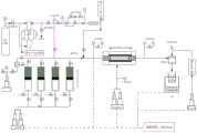
图2是本发明实施例提供的超高温高压多功能岩心驱替实验装置示意图。FIG. 2 is a schematic diagram of an ultra-high temperature and high pressure multifunctional core flooding experimental device provided in an embodiment of the present invention.
具体实施方式Detailed ways
为了使本发明的目的、技术方案及优点更加清楚明白,以下结合实施例,对本发明进行进一步详细说明。应当理解,此处所描述的具体实施例仅仅用以解释本发明,并不用于限定本发明。In order to make the objectives, technical solutions and advantages of the present invention clearer, the present invention will be further described in detail below with reference to the embodiments. It should be understood that the specific embodiments described herein are only used to explain the present invention, but not to limit the present invention.
针对现有技术存在的问题,本发明提供了一种海上深层高温超压气藏开发方法,下面结合附图对本发明作详细的描述。Aiming at the problems existing in the prior art, the present invention provides a method for developing deep offshore high temperature and overpressure gas reservoirs. The present invention will be described in detail below with reference to the accompanying drawings.
如图1所示,本发明实施例提供的海上深层高温超压气藏开发方法包括以下步骤:As shown in FIG. 1 , the method for developing an offshore deep high temperature and overpressure gas reservoir provided by an embodiment of the present invention includes the following steps:
S101:通过设置不同的初始含水饱和度、不同的CO2含量,分别对岩心设置不同的驱替压差,根据岩心出口端稳定后的气体流量确定各个岩心的渗流能力,对比分析初始含水饱和度差异、气组分中CO2含量差异对气体单相渗流能力和渗流规律的影响,确定靶区气藏的产气能力与影响因素;S101: By setting different initial water saturation and different CO2 content, different displacement pressure differences are set for the core respectively, and the seepage capacity of each core is determined according to the stable gas flow at the outlet end of the core, and the initial water saturation is compared and analyzed. The effects of differences and differences in CO2 content in gas components on gas single-phase seepage capacity and seepage law, to determine the gas production capacity and influencing factors of gas reservoirs in the target area;
S102:通过衰竭开发渗流实验模拟无边底水且含水饱和度较低储层作为参照标准,分别进行边底水储层见水机理实验和高含水储层见水机理实验,通过分析实验过程中的压力、产气量、产水量、水气比和采出程度等生产参数的动态变化规律,确定不同类型水源在不同生产条件下对气藏开发的影响,判断靶区气藏不同见水气井受何种水源的影响;S102: Use the depletion development seepage experiment to simulate the reservoir without edge and bottom water and with low water saturation as the reference standard, and conduct the water breakthrough mechanism experiment of edge and bottom water reservoirs and the water breakthrough mechanism experiment of high water-cut reservoirs respectively. The dynamic change law of production parameters such as pressure, gas production, water production, water-gas ratio and recovery degree, to determine the impact of different types of water sources on gas reservoir development under different production conditions, and to determine the impact of gas wells with different water breakthroughs in target gas reservoirs the impact of water sources;
S103:对天然岩心进行不同程度的水驱实验,模拟气井带水生产的不同阶段,并在每次水驱实验结束后分别进行矿物含量、孔隙结构特征及渗透率的测量,通过分析实验结果确定气藏见水后储层特征参数的变化规律;S103: Carry out different degrees of water flooding experiments on natural cores to simulate different stages of water-carrying production in gas wells. After each water flooding experiment, the mineral content, pore structure characteristics and permeability are measured respectively, and the results are determined by analyzing the experimental results. The changing law of reservoir characteristic parameters after water breakthrough in gas reservoirs;
S104:基于S101至S103确定的影响因素以及参数变化规律,确定气藏的开发策略以及有效开发关键参数的界限,并生成开发方案,进行海上深层高温超压气藏开发。S104: Based on the influencing factors and parameter variation rules determined in S101 to S103, determine the development strategy of the gas reservoir and the limits of key parameters for effective development, and generate a development plan for the development of deep offshore high temperature and overpressure gas reservoirs.
本发明实施例提供的步骤S101包括:Step S101 provided by the embodiment of the present invention includes:
(1)进行不同含水条件下渗流实验;(1) Carry out seepage experiments under different water content conditions;
(1.1)将准备好的岩心进行清洗、烘干8h称干重,测量岩心包括长度、直径、孔隙度和渗透率的基础物性参数;(1.1) Wash and dry the prepared core for 8 hours, weigh it dry, and measure the basic physical parameters of the core including length, diameter, porosity and permeability;
(1.2)将干岩心放入超高温高压多功能岩心驱替实验装置中进行密封,利用加热带对岩心夹持器进行加热,待加热到190℃后稳定8h;(1.2) Put the dry core into the ultra-high temperature and high pressure multifunctional core-flooding experimental device for sealing, use the heating belt to heat the core holder, and stabilize it for 8 hours after heating to 190 °C;
(1.3)用围压泵对岩心加围压至5MPa,开启驱替泵驱替气中间容器,同时同步增加岩心系统的围压和流压;当中间容器内气体用完时,对中间容器补充气体,并利用增压系统对中间容器进行加压,加压至流压后再次接入实验装置;(1.3) Use the confining pressure pump to increase the confining pressure of the core to 5MPa, open the displacement pump to displace the gas intermediate container, and simultaneously increase the confining pressure and flow pressure of the core system; when the gas in the intermediate container is used up, replenish the intermediate container gas, and use the pressurization system to pressurize the intermediate container, and then connect to the experimental device again after pressurizing to the flow pressure;
(1.4)待围压增加至95MPa时,流压增加至90MPa,保持上游和下游压力达到稳定,通过回压泵和回压阀分别设置不同的回压,模拟不同的驱替压差进行驱替实验,待出口端气流稳定后测量不同驱替压差下的气体流量,绘制气体流量-实验压差曲线图;(1.4) When the confining pressure is increased to 95MPa, the flow pressure is increased to 90MPa, and the upstream and downstream pressures are kept stable. Different backpressures are set respectively through the backpressure pump and the backpressure valve to simulate different displacement pressure differences for displacement. In the experiment, after the gas flow at the outlet is stabilized, measure the gas flow under different displacement pressure differences, and draw a gas flow-experimental pressure difference curve;
(1.5)根据靶区气藏地层水成分分析资料配置及相关矿化度的标准盐水,将盐水加入中间容器中加压至90MPa后,连入实验装置;(1.5) According to the formation water composition analysis data of the gas reservoir in the target area, configure the standard brine with relevant salinity, add the brine into the intermediate container and pressurize it to 90MPa, and then connect it to the experimental device;
(1.6)利用双柱塞驱替泵的两个泵分别控制气中间容器和水中间容器,根据岩心渗透率,设置不同的驱替流量,采用稳态法将气、水按照设置的比例即30%、40%、50%、60%和70%注入岩样,当流动达到稳定后测量进出、口压差和气体流量,绘制气体流量-实验压差曲线图;(1.6) The two pumps of the double plunger displacement pump are used to control the gas intermediate container and the water intermediate container respectively. According to the permeability of the core, different displacement flow rates are set. %, 40%, 50%, 60% and 70% are injected into the rock samples, and when the flow reaches stability, the inlet and outlet pressure difference and gas flow rate are measured, and the gas flow rate-experimental pressure difference curve is drawn;
(2)进行不同CO2含量下渗流实验;(2) Carry out seepage experiments under different CO2 contents;
(2.1)将准备好的岩心进行清洗、烘干8h称干重,测量岩心包括长度、直径、孔隙度和渗透率的基础物性参数,;(2.1) Wash and dry the prepared core for 8 hours and weigh it dry, and measure the basic physical parameters of the core including length, diameter, porosity and permeability;
(2.2)将干岩心放入实验装置中密封,利用加热带对岩心夹持器进行加热,待加热到190℃后稳定8h;先用围压泵对岩心加围压至5MPa,开启驱替泵驱替装有水的中间容器,同时同步增加岩心系统的围压和流压;(2.2) Put the dry core into the experimental device and seal it, use the heating belt to heat the core holder, and stabilize it for 8 hours after heating to 190 °C; first, use the confining pressure pump to increase the confining pressure to 5MPa, and then turn on the displacement pump Displace the intermediate container with water, and simultaneously increase the confining pressure and flow pressure of the core system;
(2.3)当中间容器内盐水用完时,对中间容器补充盐水,利用增压系统对中间容器进行加压,加压至流压后再次接入实验装置;(2.3) When the brine in the intermediate container is used up, add brine to the intermediate container, use the pressurization system to pressurize the intermediate container, and connect it to the experimental device again after pressurizing to the flow pressure;
(2.4)当围压增加至95MPa时,流压增加至90MPa,保持上游和下游压力达到稳定,采用气驱水的方式建立高温超压条件下的束缚水饱和度,以出口端不再产水为止,驱替过程中正方向对岩心进行驱替;(2.4) When the confining pressure is increased to 95MPa, the flow pressure is increased to 90MPa, and the upstream and downstream pressures are kept stable, and the irreducible water saturation under high temperature and overpressure conditions is established by means of gas-displacing water, and no water is produced at the outlet end. So far, the core is displaced in the positive direction during the displacement process;
(2.5)保持上游压力不变,通过回压泵和回压阀分别设置不同的回压,模拟不同的驱替压差进行驱替实验,待出口端气流稳定后测量不同驱替压差下的气体流量,绘制气体流量-实验压差曲线图;(2.5) Keep the upstream pressure unchanged, set different back pressures through the back pressure pump and the back pressure valve respectively, simulate different displacement pressure differences to carry out displacement experiments, and measure the pressure under different displacement pressure differences after the airflow at the outlet is stabilized. Gas flow, draw gas flow-experimental differential pressure curve;
(2.6)把N2和CO2按照实验设计中的比例即14%、28%、42%、56%和70%加入中间容器中,加压至90MPa后连入实验装置;(2.6) Add N2 and CO2 into the intermediate container according to the proportions in the experimental design, namely 14%, 28%, 42%, 56% and 70%, pressurize to 90MPa and then connect to the experimental device;
(2.7)进行驱替前要先关闭上、下游端阀门,令岩心内束缚水与CO2充分接触后再进行不同驱替压差下的驱替实验,绘制气体流量-实验压差曲线图。(2.7) Before the displacement, the upstream and downstream valves should be closed to make the irreducible water in the core fully contact withCO2 , and then the displacement experiments under different displacement pressure differences should be carried out, and the gas flow-experimental pressure difference curves should be drawn.
本发明实施例提供的步骤S102包括:Step S102 provided by the embodiment of the present invention includes:
1)进行衰竭开发渗流实验;1) Carry out the depletion development seepage experiment;
2)进行边底水储层见水机理实验2) Carry out the water breakthrough mechanism experiment of edge and bottom water reservoirs
3)进行高含水储层见水机理实验3) Carry out water breakthrough mechanism experiments in high water-cut reservoirs
4)确定临界可动水饱和度;4) Determine the critical movable water saturation;
5)基于步骤1)至步骤4)获取压力、产气量、产水量、水气比和采出程度生产参数的动态变化规律;分析压差对衰竭开采动态规律的影响;分析压差和水体溶解CO2对见水及生产特征的影响;分析压差和初始含水条件对见水及生产特征的影响;预测靶区气藏的临界可动水饱和度;确定靶区气藏不同见水气井的见水机理。5) Based on step 1) to step 4), obtain the dynamic change law of production parameters of pressure, gas production, water production, water-gas ratio and recovery degree; analyze the influence of pressure difference on the dynamic law of depletion production; analyze pressure difference and water body dissolution The effect of CO2 on water breakthrough and production characteristics; analyze the influence of pressure difference and initial water cut conditions on water breakthrough and production characteristics; predict the critical movable water saturation of gas reservoirs in the target area; See Water Mechanism.
步骤1)中,本发明实施例提供的进行衰竭开发渗流实验包括:In step 1), the depletion development seepage experiment provided in the embodiment of the present invention includes:
1.1)将准备好的岩心进行清洗、烘干8h称干重,测量岩心的长度、直径、孔隙度和渗透率相关基础物性参数,并计算拼接长岩心的总体物性;1.1) Wash and dry the prepared core for 8 hours and weigh it dry, measure the basic physical property parameters related to the length, diameter, porosity and permeability of the core, and calculate the overall physical properties of the spliced long core;
1.2)将饱和束缚水的长岩心放入全模拟实验装置密封,利用加热带对岩心夹持器进行加热,待加热到190℃后稳定8h;1.2) Put the long core saturated with irreducible water into the full simulation experimental device and seal it, use the heating belt to heat the core holder, and stabilize it for 8 hours after heating to 190 °C;
1.3)用围压泵对岩心加围压至5MPa,开启驱替泵驱替气中间容器,同时且同步增加岩心系统的围压和流压;当中间容器内气体用完时,对中间容器补充气体,并利用增压系统对中间容器进行加压,加压至流压后再次接入实验装置;1.3) Use the confining pressure pump to increase the confining pressure of the core to 5MPa, open the displacement pump to displace the gas intermediate container, and simultaneously increase the confining pressure and flow pressure of the core system; when the gas in the intermediate container is used up, replenish the intermediate container gas, and use the pressurization system to pressurize the intermediate container, and then connect to the experimental device again after pressurizing to the flow pressure;
1.5)当围压增加至95MPa时,流压增加至90MPa,待上游和下游压力达到稳定时,岩心系统达到初始地层温压系统;关闭上游进气口阀门,打开下游出气口阀门,通过回压泵和回压阀分别设置不同的回压,模拟不同的衰竭压差进行衰竭开发实验,并实时记录上、下游压力和产气量变化数据。1.5) When the confining pressure is increased to 95MPa, the flow pressure is increased to 90MPa. When the upstream and downstream pressures are stabilized, the core system reaches the initial formation temperature and pressure system; close the upstream inlet valve, open the downstream outlet valve, and pass the back pressure. The pump and the back pressure valve are respectively set with different back pressures to simulate different depletion pressure differences for depletion development experiments, and real-time recording of upstream and downstream pressure and gas production change data.
步骤2)中,本发明实施例提供的进行边底水储层见水机理实验包括:In step 2), the experiment of water breakthrough mechanism of edge and bottom water reservoirs provided by the embodiment of the present invention includes:
2.1)将准备好的岩心进行清洗、烘干8h称干重,然后测量岩心的长度、直径、孔隙度和渗透率,并计算拼接长岩心的总体物性;2.1) Wash and dry the prepared core for 8 hours and weigh it dry, then measure the length, diameter, porosity and permeability of the core, and calculate the overall physical properties of the spliced long core;
2.2)将饱和束缚水的长岩心放入全模拟实验装置中密封,利用加热带对岩心夹持器进行加热,待加热到190℃后稳定8h;将配置好的盐水注入高压中间容器中,再将配置的CO2含量35%和70%的气样过量注入高压中间容器中;2.2) Put the long core saturated with irreducible water into the full simulation experimental device and seal it, use the heating belt to heat the core holder, and stabilize it for 8 hours after heating to 190 °C; inject the prepared brine into the high-pressure intermediate container, and then Excessive injection of the configured gas samples withCO content of 35% and 70% into the high-pressure intermediate vessel;
2.3)为中间容器包裹电加热套,升温至190℃,并将中间容器连接到增压泵,使用恒压模式加压至90MPa,维持压力静置24h,使水与CO2充分接触;2.3) Wrap the electric heating jacket for the intermediate container, heat it up to 190°C, connect the intermediate container to the booster pump, use the constant pressure mode to pressurize to 90MPa, maintain the pressure for 24h, and make the water andCO2 fully contact;
2.4)待体系稳定后,打开顶部阀门,排空中间容器内未溶的多余气体,待有地层水流出时关闭阀门,再用增压泵将中间容器的压力加压至90MPa,接入实验装置中作为模拟边底水体;2.4) After the system is stable, open the top valve to empty the undissolved excess gas in the intermediate container, close the valve when the formation water flows out, and then pressurize the pressure of the intermediate container to 90MPa with a booster pump, and connect to the experimental device as a simulated edge and bottom water body;
2.5)用围压泵对岩心加围压至5MPa,然后开启驱替泵驱替气中间容器,同时同步增加岩心系统的围压和流压,当中间容器内气体用完时,对中间容器补充气体,并利用增压系统对中间容器进行加压,加压至流压后再次接入实验装置;2.5) Use the confining pressure pump to increase the confining pressure of the core to 5MPa, then open the displacement pump to displace the gas intermediate container, and simultaneously increase the confining pressure and flow pressure of the core system. When the gas in the intermediate container is used up, replenish the intermediate container gas, and use the pressurization system to pressurize the intermediate container, and then connect to the experimental device again after pressurizing to the flow pressure;
2.6)当围压增加至95MPa时,流压增加至90MPa,待上游和下游压力达到稳定时,关闭上游进气口阀门,打开上游进水口阀门和下游出液口阀门,通过回压泵和回压阀分别设置不同的回压,模拟不同的衰竭压差进行边底水条件下的衰竭开发实验,实时记录上、下游压力和产气量、产水量变化数据。2.6) When the confining pressure increases to 95MPa, the flow pressure increases to 90MPa. When the upstream and downstream pressures are stable, close the upstream air inlet valve, open the upstream water inlet valve and the downstream liquid outlet valve, and pass the back pressure pump and return valve. The pressure valves are respectively set with different back pressures to simulate different depletion pressure differences to carry out depletion development experiments under the condition of edge and bottom water, and record the upstream and downstream pressure and gas production and water production changes in real time.
步骤3)中,本发明实施例提供的进行高含水储层见水机理实验包括:In step 3), the water breakthrough mechanism experiment provided by the embodiment of the present invention includes:
3.1)将准备好的岩心进行清洗、烘干8h称干重,测量岩心的长度、直径、孔隙度和渗透率,并计算拼接长岩心的总体物性;3.1) Wash and dry the prepared core for 8 hours, weigh it dry, measure the length, diameter, porosity and permeability of the core, and calculate the overall physical properties of the spliced long core;
3.2)将未饱和水的长岩心放入实验装置密封,利用加热带对岩心夹持器进行加热,待加热到190℃后稳定8h;3.2) Put the long core with unsaturated water into the experimental device and seal it, use the heating belt to heat the core holder, and stabilize it for 8 hours after heating to 190 °C;
3.3)用围压泵对岩心加围压至5MPa,开启驱替泵驱替装有水的中间容器,同时且同步增加岩心系统的围压和流压;当中间容器内盐水用完时,对中间容器补充盐水,并利用增压系统对中间容器进行加压,加压至流压后再次接入实验装置;3.3) Use the confining pressure pump to increase the confining pressure of the core to 5MPa, open the displacement pump to displace the intermediate container with water, and simultaneously increase the confining pressure and flow pressure of the core system; when the brine in the intermediate container is used up, The intermediate container is supplemented with brine, and the intermediate container is pressurized by the pressurization system, and then connected to the experimental device again after being pressurized to the flow pressure;
3.4)待围压增加至95MPa时,流压增加至90MPa,待上游和下游压力达到稳定时,利用双柱塞驱替泵的两个泵分别控制气中间容器和水中间容器,按照设计的气水比例即35%和70%,设置相应的驱替流量进行驱替,待出口端气水比例达到设计的比例时停止;3.4) When the confining pressure is increased to 95MPa, the flow pressure is increased to 90MPa. When the upstream and downstream pressures are stabilized, the two pumps of the double plunger displacement pump are used to control the gas intermediate container and the water intermediate container respectively. The water ratio is 35% and 70%, set the corresponding displacement flow for displacement, and stop when the gas-water ratio at the outlet reaches the designed ratio;
3.5)关闭上游进气口阀门,打开下游出气口阀门,通过回压泵和回压阀分别设置不同的回压,模拟不同的衰竭压差进行衰竭开发实验,实时记录上、下游压力和产气量、产水量变化数据。3.5) Close the upstream air inlet valve, open the downstream air outlet valve, set different back pressures through the back pressure pump and the back pressure valve, simulate different depletion pressure differences for depletion development experiments, and record the upstream and downstream pressure and gas production in real time , Water production change data.
步骤4)中,本发明实施例提供的确定临界可动水饱和度包括:In step 4), determining the critical movable water saturation provided by the embodiment of the present invention includes:
4.1)获取不同驱替实验下的核磁共振T2谱图,结合进行核磁共振测试的岩心的基础物性,绘制不同物性储层可动水识别图版;4.1) Obtain the NMR T2 spectra under different displacement experiments, and draw the movable water identification plate of the reservoir with different physical properties in combination with the basic physical properties of the core tested by NMR;
4.2)结合靶区储层的物性参数范围,确定储层临界含水饱和度范围;4.2) Combined with the range of physical property parameters of the reservoir in the target area, determine the critical water saturation range of the reservoir;
4.3)结合单井测井解释成果确定每个小层的原始含水饱和度和物性,判断储层是否含有可动水。4.3) Determine the original water saturation and physical properties of each sublayer based on the results of single-well logging interpretation, and determine whether the reservoir contains movable water.
本发明实施例提供的步骤S103包括:Step S103 provided by the embodiment of the present invention includes:
(一)确定见水后微观储层关键参数变化;(1) Determining the changes of key parameters of microscopic reservoirs after water breakthrough;
首先,将准备好的岩心进行清洗、烘干8h称干重;在岩心上切取约50g的样本,研磨至小于40μm的粒径后称重;采用悬浮液等方法分离出粒径小于10μm的黏土矿物,再采用称量法得到黏土矿物的总量;First, the prepared cores were washed and dried for 8 hours and weighed dry; about 50 g of samples were cut from the cores, ground to a particle size of less than 40 μm and then weighed; the clay with a particle size of less than 10 μm was separated by suspension and other methods minerals, and then use the weighing method to obtain the total amount of clay minerals;
其次,采用粉末XRD的K值法测量各非黏土矿物的含量;记录黏土矿物总量和各非黏土矿物的含量,计算黏土矿物和常见非黏土矿物的相对含量;采用离心法提取粒径小于2μm的黏土矿物,黏土样品涂片试样,依次进行自然XRD测定、EG饱和片XRD测定和高温片XRD测定,确定非常见各黏土矿物的相对含量;Secondly, the K value method of powder XRD was used to measure the content of each non-clay mineral; the total amount of clay minerals and the content of each non-clay mineral were recorded, and the relative content of clay minerals and common non-clay minerals was calculated; centrifugation was used to extract the particle size less than 2 μm The clay minerals and clay samples were smeared and subjected to natural XRD measurement, EG saturated slice XRD measurement and high temperature slice XRD measurement in turn to determine the relative content of each unusual clay mineral;
再者,在岩心上切取一块样本,切割成10mm×10mm×5mm,把具有代表性、平整的新鲜端面作为分析面;将样本在室温下自然干燥,期间用洗耳球吹掉样本表面碎屑及灰尘,保持试样新鲜端面清洁;样本用真空镀膜仪在端面上镀一层薄金层后,放入干燥器待分析;In addition, cut a sample from the core, cut it into 10mm×10mm×5mm, and use the representative and flat fresh end face as the analysis surface; dry the sample naturally at room temperature, and blow off the surface debris of the sample with an ear-washing ball. and dust, keep the fresh end face of the sample clean; after the sample is coated with a thin gold layer on the end face with a vacuum coater, put it in a desiccator for analysis;
然后,扫面电镜开机后稳定30min以上,仪器稳定性应达到JJG 550的标准后再进行扫描电镜观察;待岩心初始条件下的两项测试结束后,将岩心抽真空,饱和地层水,采用气驱法建立束缚水,以出口端不出水为止;按照实验流程图连接实验装置,把含束缚水的岩心放入全模拟实验流程密封,加围压至5MPa,下游端连通大气;Then, after the scanning electron microscope is turned on for more than 30 minutes, the stability of the instrument should reach the standard of JJG 550, and then the scanning electron microscope observation is carried out; after the two tests under the initial conditions of the core are completed, the core is evacuated to saturate the formation water, and the gas The flooding method establishes irreducible water, until the outlet end does not produce water; connect the experimental device according to the experimental flow chart, put the core containing irreducible water into the full simulation experiment process and seal, increase the confining pressure to 5MPa, and the downstream end is connected to the atmosphere;
最后,打开上游端阀门,利用驱替泵控制水中间容器,采用恒流量的驱替方式进行水驱实验;通过驱替泵计量注入水量,当注入量达到30PV时停止实验,取出岩心进行X射线衍射和扫描电镜测试,重复上述步骤;Finally, open the upstream valve, use the displacement pump to control the water intermediate container, and use the constant flow displacement method to carry out the water flooding experiment; measure the injected water volume by the displacement pump, stop the experiment when the injection volume reaches 30PV, and take out the core for X-ray Diffraction and scanning electron microscopy tests, repeat the above steps;
(二)确定见水后宏观储层关键参数变化(2) Determine the change of key parameters of macroscopic reservoir after water breakthrough
(a)将事先准备好的岩心进行清洗、烘干8h称干重,测量岩心的长度、直径、孔隙度和渗透率;(a) Washing and drying the prepared cores for 8 hours, weighing them dry, and measuring the length, diameter, porosity and permeability of the cores;
(b)将岩心抽真空,饱和地层水,采用气驱法建立束缚水,以出口端不出水为止;(b) Evacuate the core to saturate the formation water, and use the gas flooding method to establish irreducible water until the outlet end does not produce water;
(c)将岩心放入实验装置并加温压至初始地层温压条件;(c) put the core into the experimental device and heat and press it to the initial formation temperature and pressure condition;
(d)打开上游端阀门,利用驱替泵控制水中间容器,采用恒流量的驱替方式进行水驱实验;(d) Open the valve at the upstream end, use the displacement pump to control the water intermediate container, and carry out the water flooding experiment by using the displacement method of constant flow;
(e)通过驱替泵计量注入水量,每当注入量达到5、15、30PV时停止实验,取出岩心进行渗透率的测量,绘制水驱前后渗透率变化曲线。(e) Measure the injected water volume by the displacement pump, stop the experiment when the injection volume reaches 5, 15, and 30 PV, take out the core to measure the permeability, and draw the permeability change curve before and after water flooding.
下面结合具体实施例对本发明的技术效果作进一步描述。The technical effects of the present invention will be further described below in conjunction with specific embodiments.
实施例1:Example 1:
乐东10区位于莺歌海盆地莺东斜坡带南段近凹处,水深87.0m~90.5m,属于构造+岩性气藏,受岩性控制,平面和纵向上分为多个气水系统,各个系统具有不同的压力系统。乐东10区原始地层压力系数高(压力系数2.174~2.306),压力84.1MPa~92.5MPa,正常地温度系统(地温梯度3.97℃/100m),地层温度为190℃左右。储层主要为黄流组、梅山组,属于低孔、低渗~特低渗储层,局部发育中渗储层。天然气纯烃含量26%~86%,属于干气气藏。乐东10区的多口探井在测试过程中出现产水的现象,测试水气比达到2.1~138.0m3/104m3,出水机理复杂,后续开发评价和相关研究难度大。The Ledong 10 area is located near the depression in the southern section of the Yingdong slope belt in the Yinggehai Basin, with a water depth of 87.0m-90.5m. It belongs to a structural + lithologic gas reservoir, controlled by lithology, and is divided into multiple gas-water systems in plane and longitudinal direction. , each system has a different pressure system. The original formation pressure coefficient of Ledong 10 area is high (pressure coefficient 2.174~2.306), pressure is 84.1MPa~92.5MPa, normal temperature system (geothermal gradient 3.97℃/100m), formation temperature is about 190℃. The reservoirs are mainly Huangliu Formation and Meishan Formation, which belong to low porosity, low permeability to ultra-low permeability reservoirs, and medium permeability reservoirs are locally developed. The pure hydrocarbon content of natural gas is 26% to 86%, which belongs to dry gas reservoir. During the testing process, several exploratory wells in Ledong 10 produced water. The water-gas ratio reached 2.1-138.0m3/104m3. The water-producing mechanism was complicated, and subsequent development evaluation and related research were difficult.
目前我国海上海上深层高温超压气藏(地层温度大于180℃,地层压力系数大于2.1,储层平均渗透率1.1mD)评价无经验可借鉴,乐东10区在开发评价研究过程中面临诸多瓶颈:(1)海上深层高温超压气藏渗流机理,包括不同含水饱和度及不同CO2含量下的渗流特征;(2)海上深层高温超压气藏测试过程中出现产水现象,见水机理及产水特征不明确,见水后对产能的影响;(3)海上深层高温超压气藏生产见水后对储层特征参数的影响;(4)针对该类气藏高温超压、低渗、产水等特点,对该类气藏如何制定可行的开发策略,有效开发关键参数的界限如何确定,并形成可行性研究开发方案。因此,需要通过本发明的研究解决上述瓶颈问题。At present, there is no experience to learn from the evaluation of deep high temperature and overpressure gas reservoirs in China's offshore and offshore areas (the formation temperature is greater than 180 °C, the formation pressure coefficient is greater than 2.1, and the average reservoir permeability is 1.1 mD). The Ledong 10 area faces many bottlenecks in the development evaluation and research process: (1) Seepage mechanism of deep offshore high temperature and overpressure gas reservoirs, including seepage characteristics under different water saturation and different CO2 content; (2) Water production phenomenon occurred during testing of deep offshore high temperature and overpressure gas reservoirs, water breakthrough mechanism and water production The characteristics are not clear, the impact on productivity after water breakthrough; (3) The impact on reservoir characteristic parameters after water breakthrough in deep offshore high-temperature overpressure gas reservoirs; (4) For such gas reservoirs with high temperature and overpressure, low permeability, and water and other characteristics, how to formulate feasible development strategies for such gas reservoirs, how to determine the boundaries of key parameters for effective development, and form a feasibility study and development plan. Therefore, it is necessary to solve the above-mentioned bottleneck problem through the research of the present invention.
2、课题的实验设置方案2. The experimental setup plan of the subject
2.1海上深层高温超压气藏渗流规律实验2.1 Experiment of seepage law in deep offshore high temperature and overpressure gas reservoirs
2.1.1实验原理2.1.1 Experimental principle
实验基于达西定律,通过设置不同的初始含水饱和度、不同的CO2含量,分别对岩心设置不同的驱替压差,根据岩心出口端稳定后的气体流量来确定各个岩心的渗流能力,对比分析初始含水饱和度差异、气组分中CO2含量差异对气体单相渗流能力和渗流规律的影响,进而研究靶区气藏的产气能力与影响因素。The experiment is based on Darcy's law. By setting different initial water saturation and different CO2 content, different displacement pressure differences are set for the core respectively, and the seepage capacity of each core is determined according to the stable gas flow at the outlet end of the core. The effects of the difference in initial water saturation and CO2 content in the gas composition on the gas single-phase seepage capacity and seepage law were analyzed, and then the gas production capacity and influencing factors of the gas reservoir in the target area were studied.
2.2.2实验条件2.2.2 Experimental conditions
(1)根据LD10-1区块储层物性的分布规律,选取黄流组层段渗透率范围在0.3-3.0mD的天然岩心;(1) According to the distribution law of reservoir physical properties in block LD10-1, select natural cores with permeability in the range of 0.3-3.0mD in the Huangliu Formation;
(2)实验过程完全模拟储层的高温超压(温度190℃、压力95MPa)条件;(2) The experimental process completely simulates the high temperature and overpressure conditions of the reservoir (temperature 190°C, pressure 95MPa);
(3)实验过程中采用99.9%的高纯氮气模拟天然气,根据甲方提供的《水全分析检测报告》,配置符合目标储层矿化度的标准盐水(矿化度:12800mg/L)来模拟地层水;(3) During the experiment, 99.9% high-purity nitrogen was used to simulate natural gas. According to the "Water Analysis and Testing Report" provided by Party A, standard brine (salinity: 12800mg/L) that meets the target reservoir salinity was prepared to simulate formation water;
(4)根据LD10-1-1井的测井数据,储层初始含水饱和度在31.1%~68.7%,因此实验过程设置0、30%、40%、50%、60%和70%共6种初始含水饱和度;(4) According to the logging data of Well LD10-1-1, the initial water saturation of the reservoir is between 31.1% and 68.7%, so the experimental process is set to 0, 30%, 40%, 50%, 60%, and 70%, a total of 6 kind of initial water saturation;
(5)根据LD10-1区块的测试数据,气组分中CO2含量在6.18%-69.10%,因此实验过程配置0、14%、28%、42%、56%和70%共6种CO2含量的模拟气体。(5) According to the test data of the LD10-1 block, the CO2 content in the gas composition is 6.18%-69.10%, so the experimental process is configured with 6 kinds of 0, 14%, 28%, 42%, 56% and 70%. A simulated gas withCO2 content.
2.2.3实验装置和流程图2.2.3 Experimental setup and flow chart
实验采用自主研发的超高温高压多功能岩心驱替实验装置,该实验装置的配置和实验流程如表3和图2所示。该套实验设备可应用于本项目的渗流规律实验、见水机理实验和见水后特征参数变化实验,后续实验方案中不再赘述。The experiment adopts the self-developed ultra-high temperature and high pressure multi-functional core flooding experimental device. The configuration and experimental process of the experimental device are shown in Table 3 and Figure 2. This set of experimental equipment can be applied to the seepage law experiment, the water breakthrough mechanism experiment and the characteristic parameter change experiment after water breakthrough, and will not be repeated in the subsequent experimental scheme.
表3超高温高压多功能岩心驱替实验装置配置Table 3 Configuration of ultra-high temperature and high pressure multifunctional core flooding experimental equipment

2.2.4实验步骤——不同含水条件下渗流实验2.2.4 Experimental steps - seepage experiments under different water-bearing conditions
(1)将事先准备好的岩心进行清洗、烘干8h称干重,然后测量岩心的基础物性参数,包括长度、直径、孔隙度和渗透率;(1) Wash and dry the prepared core for 8 hours and weigh it dry, and then measure the basic physical parameters of the core, including length, diameter, porosity and permeability;
(2)按照实验流程图连接实验装置,把干岩心放入全模拟实验流程密封,利用加热带对岩心夹持器进行加热,待加热到190℃后稳定8h,保证岩心内部温度达到要求;(2) Connect the experimental device according to the experimental flow chart, put the dry core into the full simulation experimental process and seal it, use the heating belt to heat the core holder, and stabilize it for 8 hours after heating to 190 °C to ensure that the internal temperature of the core meets the requirements;
(3)先用围压泵对岩心加围压至5MPa,然后开启驱替泵驱替气中间容器,同时且同步增加岩心系统的围压和流压,防止应力敏感效应对实验结果的影响;(3) First use the confining pressure pump to increase the confining pressure of the core to 5MPa, then open the displacement pump to displace the gas intermediate container, and simultaneously increase the confining pressure and flow pressure of the core system to prevent the influence of the stress-sensitive effect on the experimental results;
(4)每当中间容器内气体用完时,对中间容器补充气体,并利用增压系统对中间容器进行加压,加压至流压后再次接入实验装置;(4) Whenever the gas in the intermediate container is used up, the intermediate container is supplemented with gas, and the intermediate container is pressurized by the pressurization system, and the experimental device is connected again after being pressurized to the flow pressure;
(5)待围压增加至95MPa时,流压增加至90MPa,待上游和下游压力达到稳定时,此刻岩心系统已经达到初始地层温压系统;(5) When the confining pressure is increased to 95MPa, the flow pressure is increased to 90MPa, and when the upstream and downstream pressures are stabilized, the core system has reached the initial formation temperature and pressure system at this moment;
(6)保持上游压力不变,通过回压泵和回压阀分别设置不同的回压,模拟不同的驱替压差(0.1-10MPa)进行驱替实验,待出口端气流稳定后测量不同驱替压差下的气体流量,绘制气体流量-实验压差曲线图;(6) Keep the upstream pressure unchanged, set different back pressures through the back pressure pump and the back pressure valve, simulate different displacement pressure differences (0.1-10MPa) for displacement experiments, and measure the different displacements after the airflow at the outlet is stable. Instead of the gas flow under the pressure difference, draw a gas flow-experimental pressure difference curve;
(7)根据靶区气藏地层水成分分析资料配置等矿化度的标准盐水,并将盐水加入中间容器中加压至90MPa后,连入实验装置;(7) Prepare standard brine with equal salinity according to the formation water composition analysis data of the gas reservoir in the target area, add the brine into the intermediate container and pressurize it to 90MPa, and then connect it to the experimental device;
(8)利用双柱塞驱替泵的两个泵分别控制气中间容器和水中间容器,根据岩心渗透率,设置不同的驱替流量(根据步骤6中的测试结果进行设置),采用稳态法将气、水按照设置的比例(30%、40%、50%、60%和70%)注入岩样,等流动达到稳定后测量进出、口压差和气体流量,绘制气体流量-实验压差曲线图。(8) Use the two pumps of the double plunger displacement pump to control the gas intermediate container and the water intermediate container respectively, set different displacement flow rates according to the core permeability (set according to the test results in step 6), and use steady state The method injects gas and water into the rock sample according to the set proportions (30%, 40%, 50%, 60% and 70%), waits for the flow to stabilize, and measures the inlet and outlet pressure difference and gas flow, and draws the gas flow-experimental pressure. difference graph.
2.2.5实验步骤——不同CO2含量下渗流实验2.2.5 Experimental steps - seepage experiments under different CO2 contents
(1)将事先准备好的岩心进行清洗、烘干8h称干重,然后测量岩心的基础物性参数,包括长度、直径、孔隙度和渗透率;(1) Wash and dry the prepared core for 8 hours and weigh it dry, and then measure the basic physical parameters of the core, including length, diameter, porosity and permeability;
(2)按照实验流程图连接实验装置,把干岩心放入全模拟实验流程密封,利用加热带对岩心夹持器进行加热,待加热到190℃后稳定8h,保证岩心内部温度达到要求;(2) Connect the experimental device according to the experimental flow chart, put the dry core into the full simulation experimental process and seal it, use the heating belt to heat the core holder, and stabilize it for 8 hours after heating to 190 °C to ensure that the internal temperature of the core meets the requirements;
(3)先用围压泵对岩心加围压至5MPa,然后开启驱替泵驱替装有水的中间容器,同时且同步增加岩心系统的围压和流压,防止应力敏感效应对实验结果的影响;(3) First use the confining pressure pump to increase the confining pressure of the core to 5MPa, then turn on the displacement pump to displace the intermediate container with water, and simultaneously increase the confining pressure and flow pressure of the core system to prevent the stress-sensitive effect from affecting the experimental results. Impact;
(4)每当中间容器内盐水用完时,对中间容器补充盐水,并利用增压系统对中间容器进行加压,加压至流压后再次接入实验装置;(4) Whenever the brine in the intermediate container is used up, the intermediate container is supplemented with brine, and the intermediate container is pressurized by the pressurization system, and the experimental device is connected again after being pressurized to the flow pressure;
(5)待围压增加至95MPa时,流压增加至90MPa,待上游和下游压力达到稳定时,此刻岩心系统已经达到初始地层温压系统,且100%饱和地层水;(5) When the confining pressure is increased to 95MPa, the flow pressure is increased to 90MPa, and when the upstream and downstream pressures are stabilized, the core system has reached the initial formation temperature and pressure system at this moment, and the formation water is 100% saturated;
(6)采用气驱水的方式建立高温超压条件下的束缚水饱和度,以出口端不再产水为止,驱替过程中需要正方向对岩心进行驱替,以使束缚水均匀分布;(6) The irreducible water saturation under the condition of high temperature and overpressure is established by means of gas-displacing water, until the outlet end no longer produces water, and the core needs to be displaced in the positive direction during the displacement process to make the irreducible water evenly distributed;
(7)保持上游压力不变,通过回压泵和回压阀分别设置不同的回压,模拟不同的驱替压差(0.1-10MPa)进行驱替实验,待出口端气流稳定后测量不同驱替压差下的气体流量,绘制气体流量-实验压差曲线图;(7) Keep the upstream pressure unchanged, set different back pressures through the back pressure pump and the back pressure valve respectively, simulate different displacement pressure differences (0.1-10MPa) for displacement experiments, and measure the different displacements after the gas flow at the outlet is stable. Instead of the gas flow under the pressure difference, draw a gas flow-experimental pressure difference curve;
(8)把N2和CO2按照实验设计中的比例(14%、28%、42%、56%和70%)加入中间容器中,加压至90MPa后连入实验装置;(8) Add N2 and CO2 into the intermediate container according to the proportions in the experimental design (14%, 28%, 42%, 56% and 70%), pressurize to 90MPa and then connect to the experimental device;
(9)每次进行驱替前要先关闭上、下游端阀门,使岩心内束缚水与CO2充分接触后再进行不同驱替压差(0.1-10MPa)下的驱替实验,绘制气体流量-实验压差曲线图。(9) Before each displacement, the upstream and downstream valves should be closed to make the irreducible water in the core fully contact with CO2 , and then the displacement experiments under different displacement pressure differences (0.1-10MPa) should be carried out, and the gas flow rate should be drawn. - Graph of experimental differential pressure.
2.2.6实验明细2.2.6 Experiment Details

2.2.7实验记录表2.2.7 Experiment record sheet


2.2.8预期成果2.2.8 Expected results
(1)获得高温超压条件下单相气体渗流特征曲线;(1) Obtain the characteristic curve of single-phase gas seepage under the condition of high temperature and overpressure;
(2)分析不同含水饱和度、不同CO2含量对气体渗流能力的影响;(2) Analyze the effect of different water saturation and CO2 content on the gas seepage capacity;
(3)预测不同含水条件、不同CO2含量条件下的储层的产气能力;(3) Predict the gas production capacity of the reservoir under different water-cut conditions and different CO2 content conditions;
(4)实验结果可为产能模拟法确定有效储层物性下限提供数据支持。(4) The experimental results can provide data support for determining the lower limit of effective reservoir physical properties by the productivity simulation method.
2.2海上深层高温超压气藏见水机理实验2.2 Experiment on the mechanism of water breakthrough in deep offshore high temperature and overpressure gas reservoirs
2.2.1实验原理2.2.1 Experimental principle
实验以国家行业标准(GB/T 28912-2012岩石中两相流体相对渗透率测定方法)为基础,对实验设备和实验方法进行改进,设备上搭建高温超压多功能驱替实验装置,引入增压泵、电加热套和耐高温高压材料等新仪器;方法上通过衰竭开发渗流实验模拟无边底水且含水饱和度较低储层作为参照标准,再分别进行边底水储层见水机理实验和高含水储层见水机理实验,通过分析实验过程中的压力、产气量和采出程度的动态变化规律,研究不同类型水源对气藏开发的影响,进而判断靶区气藏不同见水气井受何种水源的影响。The experiment is based on the national industry standard (GB/T 28912-2012 Method for Determination of Relative Permeability of Two-Phase Fluids in Rocks), and the experimental equipment and experimental methods are improved. New instruments such as pressure pumps, electric heating jackets, and high temperature and high pressure resistant materials; methodically, the depletion and development seepage experiments are used to simulate the reservoirs with boundless bottom water and low water saturation as the reference standard, and then the water breakthrough mechanism experiments of the edge and bottom water reservoirs are carried out respectively. And high water-cut reservoir water breakthrough mechanism experiment, by analyzing the dynamic change law of pressure, gas production and recovery degree during the experiment, to study the impact of different types of water sources on gas reservoir development, and then to judge the different water breakthrough gas wells in target gas reservoirs affected by the water source.
2.2.2实验条件2.2.2 Experimental conditions
(1)根据LD10-1区块储层物性的分布规律,选取黄流组层段相同渗透率范围(0.3-3.0mD)的岩心3块,拼接成长岩心,降低单一柱塞岩心的边界效应;(1) According to the distribution law of the reservoir physical properties in the LD10-1 block, three cores with the same permeability range (0.3-3.0mD) in the Huangliu Formation were selected and spliced to grow cores to reduce the boundary effect of a single plunger core;
(2)实验过程完全模拟储层的高温超压(温度190℃、压力95MPa)条件;(2) The experimental process completely simulates the high temperature and overpressure conditions of the reservoir (temperature 190°C, pressure 95MPa);
(3)实验过程中采用99.9%的高纯氮气模拟天然气,根据甲方提供的《水全分析检测报告》,配置符合目标储层矿化度的标准盐水(矿化度:12800mg/L)来模拟地层水;(3) During the experiment, 99.9% high-purity nitrogen was used to simulate natural gas. According to the "Water Analysis and Testing Report" provided by Party A, standard brine (salinity: 12800mg/L) that meets the target reservoir salinity was prepared to simulate formation water;
(4)根据LD10-1-1井的测井数据,储层初始含水饱和度在31.1%~68.7%,因此实验过程设置含水饱和度35%和70%分别代表较低含水和较高含水层;(4) According to the logging data of Well LD10-1-1, the initial water saturation of the reservoir is in the range of 31.1% to 68.7%, so the experimental process set the water saturation to 35% and 70% to represent the lower and higher water-cut layers, respectively ;
(5)根据LD10-1区块的测试数据,气组分中CO2含量在6.18%-69.10%,因此实验过程分别将CO2含量35%和70%的模拟气体注入水中间容器中,充分静置使CO2和盐水充分接触,然后将水排出中间容器,以模拟较低含CO2和较高含CO2边底水体。(5) According to the test data of the LD10-1 block, theCO2 content in the gas component is 6.18%-69.10%, so the simulated gas with aCO2 content of 35% and 70% was injected into the water intermediate container during the experiment, and it was fully Set aside to allow sufficient contact of theCO2 and brine, and then drain the water out of the intermediate vessel to simulate lowerCO2 and higherCO2 side-bottom water bodies.
(6)根据LD10-1区块的测试数据,3井4层次的压差分别为12.2MPa、32.6MPa、62.7MPa和62.9MPa,因此设置实验压差5、10、15和30MPa分别代表不同的生产压差(15、30、45和60MPa)。(6) According to the test data of the LD10-1 block, the pressure differences of the 3 wells and the 4 layers are 12.2MPa, 32.6MPa, 62.7MPa and 62.9MPa respectively. Therefore, the experimental pressure differences of 5, 10, 15 and 30MPa represent different Production differential pressure (15, 30, 45 and 60 MPa).
(7)根据水的三相相态图,在190℃时水从液体汽化为气体时所需要的压力在1.5MPa左右,而岩心中压力始终高于1.5MPa,因此实验中不需要考虑水的汽化现象;而在实验出口端水的计量系统里面设置有冷凝装置,可将汽化的水冷凝为液体进行计量。(7) According to the three-phase state diagram of water, the pressure required for water to vaporize from liquid to gas at 190°C is about 1.5MPa, while the core pressure is always higher than 1.5MPa, so there is no need to consider water in the experiment. There is a condensation device in the metering system of the water at the outlet of the experiment, which can condense the vaporized water into liquid for metering.
2.2.3实验步骤——衰竭开发渗流实验2.2.3 Experimental steps - depletion development seepage experiment
(1)将事先准备好的岩心进行清洗、烘干8h称干重,然后测量岩心的基础物性参数,包括长度、直径、孔隙度和渗透率,并计算拼接长岩心的总体物性;(1) Wash and dry the prepared core for 8 hours and weigh it dry, then measure the basic physical parameters of the core, including length, diameter, porosity and permeability, and calculate the overall physical properties of the spliced long core;
(2)按照实验流程图连接实验装置,把饱和束缚水的长岩心放入全模拟实验流程密封,利用加热带对岩心夹持器进行加热,待加热到190℃后稳定8h,保证岩心内部温度达到要求;(2) Connect the experimental device according to the experimental flow chart, put the long core saturated with irreducible water into the full simulation experimental process and seal, use the heating belt to heat the core holder, and stabilize it for 8 hours after heating to 190 °C to ensure the internal temperature of the core Meet the requirements;
(3)先用围压泵对岩心加围压至5MPa,然后开启驱替泵驱替气中间容器,同时且同步增加岩心系统的围压和流压,防止应力敏感效应对实验结果的影响;(3) First use the confining pressure pump to increase the confining pressure of the core to 5MPa, then open the displacement pump to displace the gas intermediate container, and simultaneously increase the confining pressure and flow pressure of the core system to prevent the influence of the stress-sensitive effect on the experimental results;
(4)每当中间容器内气体用完时,对中间容器补充气体,并利用增压系统对中间容器进行加压,加压至流压后再次接入实验装置;(4) Whenever the gas in the intermediate container is used up, the intermediate container is supplemented with gas, and the intermediate container is pressurized by the pressurization system, and the experimental device is connected again after being pressurized to the flow pressure;
(5)待围压增加至95MPa时,流压增加至90MPa,待上游和下游压力达到稳定时,此刻岩心系统已经达到初始地层温压系统;(5) When the confining pressure is increased to 95MPa, the flow pressure is increased to 90MPa, and when the upstream and downstream pressures are stabilized, the core system has reached the initial formation temperature and pressure system at this moment;
(6)关闭上游进气口阀门,打开下游出气口阀门,通过回压泵和回压阀分别设置不同的回压,模拟不同的衰竭压差(5、10、15和30MPa)进行衰竭开发实验,实验过程中实时记录上、下游压力和产气量变化数据。(6) Close the upstream air inlet valve, open the downstream air outlet valve, set different back pressures through the back pressure pump and the back pressure valve, and simulate different depletion pressure differences (5, 10, 15 and 30MPa) for depletion development experiments , real-time recording of upstream and downstream pressure and gas production change data during the experiment.
2.2.4实验步骤——边底水储层见水机理实验2.2.4 Experimental steps - water breakthrough mechanism experiment of edge and bottom water reservoirs
(1)将事先准备好的岩心进行清洗、烘干8h称干重,然后测量岩心的基础物性参数,包括长度、直径、孔隙度和渗透率,并计算拼接长岩心的总体物性;(1) Wash and dry the prepared core for 8 hours and weigh it dry, then measure the basic physical parameters of the core, including length, diameter, porosity and permeability, and calculate the overall physical properties of the spliced long core;
(2)按照实验流程图连接实验装置,把饱和束缚水的长岩心放入全模拟实验流程密封,利用加热带对岩心夹持器进行加热,待加热到190℃后稳定8h,保证岩心内部温度达到要求;(2) Connect the experimental device according to the experimental flow chart, put the long core saturated with irreducible water into the full simulation experimental process and seal, use the heating belt to heat the core holder, and stabilize it for 8 hours after heating to 190 °C to ensure the internal temperature of the core Meet the requirements;
(3)将配置好的盐水注入高压中间容器中,再将配置的CO2含量35%和70%的气样过量注入高压中间容器中;(3) Inject the prepared brine into the high-pressure intermediate container, and then inject the configured gas samples with aCO content of 35% and 70% into the high-pressure intermediate container excessively;
(4)为中间容器包裹电加热套,升温至190℃,并将中间容器连接到增压泵,使用恒压模式加压至90MPa,维持压力静置24h,使水与CO2充分接触;(4) Wrap the electric heating jacket for the intermediate container, heat up to 190°C, connect the intermediate container to the booster pump, use the constant pressure mode to pressurize to 90MPa, maintain the pressure for 24h, and make the water andCO2 fully contact;
(5)待体系稳定后,此时地层水位于中间容器的底部。打开顶部阀门,排空中间容器内未溶的多余气体,待有地层水流出时关闭阀门,再用增压泵将中间容器的压力加压至90MPa,接入实验装置中作为模拟边底水体;(5) After the system is stabilized, the formation water is at the bottom of the intermediate container. Open the top valve to empty the undissolved excess gas in the intermediate container, close the valve when formation water flows out, and then pressurize the pressure of the intermediate container to 90MPa with a booster pump, and connect it to the experimental device as a simulated edge and bottom water body;
(6)先用围压泵对岩心加围压至5MPa,然后开启驱替泵驱替气中间容器,同时且同步增加岩心系统的围压和流压,防止应力敏感效应对实验结果的影响;(6) First, use the confining pressure pump to increase the confining pressure of the core to 5MPa, then open the displacement pump to displace the gas intermediate container, and simultaneously increase the confining pressure and flow pressure of the core system to prevent the influence of the stress-sensitive effect on the experimental results;
(7)每当中间容器内气体用完时,对中间容器补充气体,并利用增压系统对中间容器进行加压,加压至流压后再次接入实验装置;(7) Whenever the gas in the intermediate container is used up, the intermediate container is supplemented with gas, and the intermediate container is pressurized by the pressurization system, and the experimental device is connected again after being pressurized to the flow pressure;
(8)待围压增加至95MPa时,流压增加至90MPa,待上游和下游压力达到稳定时,此刻岩心系统已经达到初始地层温压系统;(8) When the confining pressure is increased to 95MPa, the flow pressure is increased to 90MPa, and when the upstream and downstream pressures are stabilized, the core system has reached the initial formation temperature and pressure system at this moment;
(9)关闭上游进气口阀门,打开上游进水口阀门和下游出液口阀门,通过回压泵和回压阀分别设置不同的回压,模拟不同的衰竭压差(5、10、15和30MPa)进行边底水条件下的衰竭开发实验,实验过程中实时记录上、下游压力和产气量、产水量变化数据。(9) Close the upstream air inlet valve, open the upstream water inlet valve and the downstream liquid outlet valve, and set different back pressures through the back pressure pump and back pressure valve to simulate different depletion pressure differences (5, 10, 15 and 30MPa) to carry out the depletion development experiment under the condition of edge and bottom water. During the experiment, the upstream and downstream pressure and the change data of gas production and water production were recorded in real time.
2.2.5实验步骤——高含水储层见水机理实验2.2.5 Experimental steps - water breakthrough mechanism experiment in high water-cut reservoirs
(1)将事先准备好的岩心进行清洗、烘干8h称干重,然后测量岩心的基础物性参数,包括长度、直径、孔隙度和渗透率,并计算拼接长岩心的总体物性;(1) Wash and dry the prepared core for 8 hours and weigh it dry, then measure the basic physical parameters of the core, including length, diameter, porosity and permeability, and calculate the overall physical properties of the spliced long core;
(2)按照实验流程图连接实验装置,把未饱和水的长岩心放入全模拟实验流程密封,利用加热带对岩心夹持器进行加热,待加热到190℃后稳定8h,保证岩心内部温度达到要求;(2) Connect the experimental device according to the experimental flow chart, put the long core with unsaturated water into the full simulation experimental process to seal, use the heating belt to heat the core holder, and stabilize it for 8 hours after heating to 190 °C to ensure the internal temperature of the core. Meet the requirements;
(3)先用围压泵对岩心加围压至5MPa,然后开启驱替泵驱替装有水的中间容器,同时且同步增加岩心系统的围压和流压,防止应力敏感效应对实验结果的影响;(3) First use the confining pressure pump to increase the confining pressure of the core to 5MPa, then turn on the displacement pump to displace the intermediate container with water, and simultaneously increase the confining pressure and flow pressure of the core system to prevent the stress-sensitive effect from affecting the experimental results. Impact;
(5)每当中间容器内盐水用完时,对中间容器补充盐水,并利用增压系统对中间容器进行加压,加压至流压后再次接入实验装置;(5) Whenever the brine in the intermediate container is used up, the intermediate container is supplemented with brine, and the intermediate container is pressurized by the pressurization system, and the experimental device is connected again after being pressurized to the flow pressure;
(6)待围压增加至95MPa时,流压增加至90MPa,待上游和下游压力达到稳定时,此刻岩心系统已经达到初始地层温压系统,且100%饱和地层水;(6) When the confining pressure is increased to 95MPa, the flow pressure is increased to 90MPa, and when the upstream and downstream pressures are stabilized, the core system has reached the initial formation temperature and pressure system at this moment, and the formation water is 100% saturated;
(7)利用双柱塞驱替泵的两个泵分别控制气中间容器和水中间容器,按照设计的气水比例(35%和70%),设置相应的驱替流量进行驱替,待出口端气水比例达到设计的比例时停止,此刻岩心系统已经达到不同的初始含水条件;(7) Use the two pumps of the double plunger displacement pump to control the gas intermediate container and the water intermediate container respectively. According to the designed gas-water ratio (35% and 70%), set the corresponding displacement flow for displacement, and wait for the outlet. Stop when the gas-water ratio at the end reaches the designed ratio, and the core system has reached different initial water-bearing conditions at this moment;
(8)关闭上游进气口阀门,打开下游出气口阀门,通过回压泵和回压阀分别设置不同的回压,模拟不同的衰竭压差(5、10、15和30MPa)进行衰竭开发实验,实验过程中实时记录上、下游压力和产气量、产水量变化数据。(8) Close the upstream air inlet valve, open the downstream air outlet valve, set different back pressures through the back pressure pump and the back pressure valve respectively, and simulate different depletion pressure differences (5, 10, 15 and 30MPa) for depletion development experiments During the experiment, the upstream and downstream pressure, gas production and water production change data were recorded in real time.
2.2.6实验步骤——临界可动水饱和度研究2.2.6 Experimental steps - study of critical movable water saturation
(1)获取不同驱替实验下的核磁共振T2谱图,由甲方提供(西南石油大学外协项目)(1) Obtain NMR T2 spectra under different displacement experiments, provided by Party A (Southwest Petroleum University Outsourcing Project)
(2)结合进行核磁共振测试的岩心的基础物性,绘制不同物性储层可动水识别图版;(2) Based on the basic physical properties of the cores tested by NMR, draw the movable water identification plate of the reservoir with different physical properties;
(3)结合靶区储层的物性参数范围,确定储层临界含水饱和度范围;(3) Determine the critical water saturation range of the reservoir in combination with the physical property parameter range of the reservoir in the target area;
(4)结合单井测井解释成果确定每个小层的原始含水饱和度和物性,判断储层是否含有可动水。(4) Determine the original water saturation and physical properties of each sublayer based on the results of single-well logging interpretation, and determine whether the reservoir contains movable water.
2.2.7实验明细2.2.7 Experiment Details


2.2.8实验记录表2.2.8 Experiment record sheet


2.2.9预期成果2.2.9 Expected results
(1)获取压力、产量和采收率在衰竭开采过程中的动态变化规律;(1) Obtain the dynamic change law of pressure, production and recovery during depletion mining;
(2)分析压差对衰竭开采动态规律的影响;(2) Analyze the influence of differential pressure on the dynamic law of depletion production;
(3)分析压差和水体溶解CO2对见水及生产特征的影响;(3) Analyze the influence of differential pressure and dissolved CO2 in water on water breakthrough and production characteristics;
(4)分析压差和初始含水条件对见水及生产特征的影响;(4) Analyze the influence of differential pressure and initial water content on water breakthrough and production characteristics;
(5)预测靶区气藏的临界可动水饱和度;(5) Predict the critical movable water saturation of the gas reservoir in the target area;
(6)揭示靶区气藏不同见水气井的见水机理。(6) Reveal the water breakthrough mechanism of different water breakthrough gas wells in target gas reservoirs.
2.3海上深层高温超压气藏见水后储层关键参数变化2.3 Changes of key reservoir parameters after water breakthrough in deep offshore high temperature and overpressure gas reservoirs
2.3.1实验原理2.3.1 Experimental principle
实验以石油与天然气行业标准(SY/T 5163-2010沉积岩中黏土矿物和常见非黏土矿物X衍射分析方法、SY/T 6103-2004岩石孔隙结构特征的测定图像分析法和GB/T 17361-2013微束分析沉积岩中自生粘土矿物鉴定扫描电子显微镜及能谱仪方法)为基础,对天然岩心进行不同程度的水驱实验,模拟气井带水生产的不同阶段。每次水驱实验结束后分别进行矿物含量、孔隙结构特征及渗透率的测量,通过分析实验结果从微观和宏观两个层面研究气藏见水后储层特征参数的变化规律,判断储层是否可以长期带水生产。The experiment is based on the petroleum and natural gas industry standard (SY/T 5163-2010 X-ray diffraction analysis method of clay minerals and common non-clay minerals in sedimentary rocks, SY/T 6103-2004 Determination of rock pore structure characteristics and image analysis method and GB/T 17361-2013 Based on microbeam analysis and identification of authigenic clay minerals in sedimentary rocks, scanning electron microscopy and energy dispersive spectrometer methods), different degrees of water flooding experiments were carried out on natural cores to simulate different stages of water production in gas wells. After each water flooding experiment, the mineral content, pore structure characteristics and permeability were measured respectively. By analyzing the experimental results, the change law of the reservoir characteristic parameters after water breakthrough was studied from the microscopic and macroscopic levels to judge whether the reservoir is not. It can be produced with water for a long time.
2.3.2实验条件2.3.2 Experimental conditions
(1)根据LD10-1区块储层物性的分布规律,选取黄流组层段渗透率范围在0.3-3.0mD的天然岩心;(1) According to the distribution law of reservoir physical properties in block LD10-1, select natural cores with permeability in the range of 0.3-3.0mD in the Huangliu Formation;
(2)测量宏观参数的水驱实验在高温超压条件下进行,测量微观参数的X射线衍射和电镜扫描在室内温压条件下进行,分别测量水驱前后水驱后的微观参数特征;(2) The water flooding experiment for measuring macroscopic parameters was carried out under high temperature and overpressure conditions, and the X-ray diffraction and electron microscopy scanning for measuring microscopic parameters were carried out under indoor temperature and pressure conditions, and the characteristics of microscopic parameters before and after water flooding were measured respectively;
(3)实验过程中采用99.9%的高纯氮气模拟天然气,根据甲方提供的《水全分析检测报告》,配置符合目标储层矿化度的标准盐水(矿化度:12800mg/L)来模拟地层水;(3) During the experiment, 99.9% high-purity nitrogen was used to simulate natural gas. According to the "Water Analysis and Testing Report" provided by Party A, standard brine (salinity: 12800mg/L) that meets the target reservoir salinity was prepared to simulate formation water;
(4)实验中设计5、15和30PV共3个水体倍数进行恒压差(10和20MPa)水驱实验,分别模拟短期、中期和长期水侵过程。(4) In the experiment, three water body multiples of 5, 15 and 30 PV were designed to conduct water flooding experiments with constant pressure difference (10 and 20 MPa) to simulate the short-term, medium-term and long-term water influx processes, respectively.
2.3.3实验步骤——见水后微观储层关键参数变化2.3.3 Experimental steps—changes in key parameters of microscopic reservoirs after water breakthrough
(1)将事先准备好的岩心进行清洗、烘干8h称干重;(1) Wash and dry the prepared cores for 8h and weigh them dry;
(2)在岩心上切取约50g的样本,研磨至小于40μm的粒径后称重;(2) A sample of about 50g was cut from the core, ground to a particle size of less than 40μm and weighed;
(3)采用悬浮液等方法分离出粒径小于10μm的黏土矿物,再采用称量法得到黏土矿物的总量;(3) Separating clay minerals with particle size less than 10 μm by methods such as suspension, and then using weighing method to obtain the total amount of clay minerals;
(4)采用粉末XRD“K值法”测量各非黏土矿物的含量;(4) The content of each non-clay mineral was measured by powder XRD "K value method";
(5)记录黏土矿物总量和各非黏土矿物的含量,计算黏土矿物和常见非黏土矿物的相对含量;(5) Record the total amount of clay minerals and the content of each non-clay mineral, and calculate the relative content of clay minerals and common non-clay minerals;
(6)然后采用离心法提取粒径小于2μm的黏土矿物,黏土样品涂片试样,依次进行自然XRD测定、EG饱和片XRD测定和高温片XRD测定,确定非常见各黏土矿物的相对含量;(6) Then adopt centrifugal method to extract clay minerals with particle size less than 2 μm, and smear samples of clay samples, and perform natural XRD measurement, EG saturated slice XRD measurement and high temperature slice XRD measurement in turn to determine the relative content of each unusual clay mineral;
(7)再在岩心上切取一块样本,切割成10mm×10mm×5mm,把具有代表性、平整的新鲜端面作为分析面;(7) Cut a sample from the core, cut it into 10mm×10mm×5mm, and use the representative and flat fresh end face as the analysis surface;
(8)将样本在室温下自然干燥,期间用洗耳球吹掉样本表面碎屑及灰尘,保持试样新鲜端面清洁;(8) Dry the sample naturally at room temperature, blow off the debris and dust on the surface of the sample with an ear-washing ball, and keep the fresh end face of the sample clean;
(9)样本用真空镀膜仪在端面上镀一层薄金层后,放入干燥器待分析;(9) After the sample is coated with a thin gold layer on the end face with a vacuum coater, it is put into a desiccator for analysis;
(10)扫面电镜开机后要稳定30min以上,仪器稳定性应达到JJG 550的标准后再进行扫描电镜观察;(10) After the scanning electron microscope is turned on, it should be stable for more than 30 minutes, and the stability of the instrument should reach the standard of JJG 550 before the scanning electron microscope observation;
(11)待岩心初始条件下的两项测试结束后,将岩心抽真空,饱和地层水,采用气驱法建立束缚水,以出口端不出水为止;(11) After the two tests under the initial conditions of the core are completed, the core is evacuated to saturate the formation water, and the gas flooding method is used to establish the irreducible water, until the outlet end does not produce water;
(12)按照实验流程图连接实验装置,把含束缚水的岩心放入全模拟实验流程密封,加围压至5MPa,下游端连通大气;(12) Connect the experimental device according to the experimental flow chart, put the core containing irreducible water into the full simulation experimental process and seal, increase the confining pressure to 5MPa, and the downstream end is connected to the atmosphere;
(13)打开上游端阀门,利用驱替泵控制水中间容器,采用恒流量的驱替方式进行水驱实验;(13) Open the valve at the upstream end, use the displacement pump to control the water intermediate container, and carry out the water flooding experiment by using the displacement method of constant flow;
(14)通过驱替泵计量注入水量,当注入量达到30PV时停止实验,取出岩心进行X射线衍射和扫描电镜测试,重复上述步骤(1)~(10)。(14) Measure the injected water volume by the displacement pump, stop the experiment when the injection volume reaches 30PV, take out the core for X-ray diffraction and scanning electron microscopy tests, and repeat the above steps (1) to (10).
2.3.4实验步骤——见水后宏观储层关键参数变化2.3.4 Experimental steps - changes in key parameters of macroscopic reservoirs after water breakthrough
(1)将事先准备好的岩心进行清洗、烘干8h称干重,然后测量岩心的基础物性参数,包括长度、直径、孔隙度和渗透率;(1) Wash and dry the prepared core for 8 hours and weigh it dry, and then measure the basic physical parameters of the core, including length, diameter, porosity and permeability;
(2)将岩心抽真空,饱和地层水,采用气驱法建立束缚水,以出口端不出水为止;(2) The core is evacuated to saturate the formation water, and the gas flooding method is used to establish the irreducible water, until the outlet end does not produce water;
(3)按照实验流程图连接实验装置,放入岩心并加温压至初始地层温压条件;(3) Connect the experimental device according to the experimental flow chart, put in the core and heat and press it to the initial formation temperature and pressure conditions;
(4)打开上游端阀门,利用驱替泵控制水中间容器,采用恒流量的驱替方式进行水驱实验;(4) Open the upstream valve, use the displacement pump to control the water intermediate container, and use the constant flow displacement method to carry out the water flooding experiment;
(5)通过驱替泵计量注入水量,每当注入量达到5、15、30PV时停止实验,取出岩心进行渗透率的测量,绘制水驱前后渗透率变化曲线。(5) Measure the injected water volume by the displacement pump, stop the experiment when the injection volume reaches 5, 15, and 30 PV, take out the core to measure the permeability, and draw the permeability change curve before and after water flooding.
2.3.5实验明细2.3.5 Experiment Details

2.3.6实验记录表2.3.6 Experiment record sheet

2.3.7预期成果2.3.7 Expected results
(1)揭示不同水侵程度下储层黏土矿物和孔隙结构的变化特征;(1) Reveal the variation characteristics of reservoir clay minerals and pore structure under different water invasion degrees;
(2)揭示不同水侵程度下的储层渗透率变化规律;(2) Reveal the variation law of reservoir permeability under different water invasion degrees;
(3)从宏观和微观两个层面分析气井见水后储层关键参数变化及对生产的影响。(3) Analyze the changes of key reservoir parameters and their impact on production after water breakthrough in gas wells from both macro and micro levels.
3、实验研究进度安排3. Schedule of experimental research
3.1实验周期3.1 Experiment period
高温超压实验周期长,实验准备(加压、稳定、泄压)和数据处理需要更长的时间,在保证100%成功率的前提下需要188天的工作时长。高温超压实验成功率较低,以往项目实验成功率在70%左右。具体实验周期如下表所示。The high temperature and overpressure experiment has a long cycle, and the experiment preparation (pressurization, stabilization, pressure relief) and data processing take longer, and it takes 188 days to work under the premise of ensuring a 100% success rate. The success rate of high temperature and overpressure experiments is low, and the success rate of previous projects is about 70%. The specific experimental period is shown in the table below.
表4实验周期Table 4 Experimental period

3.2实验进度3.2 Experiment progress
综合考虑实验周期和实验成功率,实验研究部分预期在2020年9月底完成;在保证完成计划实验数量的前提下,增加实验数量,力求超额完成项目要求。Taking into account the experimental period and the experimental success rate, the experimental research part is expected to be completed by the end of September 2020; on the premise of ensuring the completion of the planned number of experiments, the number of experiments will be increased, and efforts will be made to exceed the project requirements.
表5实验进度安排Table 5 Experimental schedule


3.3岩心需求3.3 Core requirements
由于高温超压实验失败率较高,岩心容易损坏,因此需要准备备用岩心,岩心损坏后及时更换,以免影响实验进度,总共需要16块岩心;其他课题已使用完毕的岩心在保障完整性和渗透率要求的前提下也可使用。Due to the high failure rate of high temperature and overpressure experiments, the core is easily damaged, so it is necessary to prepare spare cores and replace them in time after damage to avoid affecting the progress of the experiment. A total of 16 cores are required; the cores that have been used for other topics are used to ensure integrity and permeability. It can also be used under the premise of rate requirements.
表6岩心需求安排Table 6 Core Demand Arrangement


以上所述,仅为本发明的具体实施方式,但本发明的保护范围并不局限于此,任何熟悉本技术领域的技术人员在本发明揭露的技术范围内,凡在本发明的精神和原则之内所作的任何修改、等同替换和改进等,都应涵盖在本发明的保护范围之内。The above are only specific embodiments of the present invention, but the protection scope of the present invention is not limited to this. Any person skilled in the art is within the technical scope disclosed by the present invention, and all within the spirit and principle of the present invention Any modifications, equivalent replacements and improvements made within the scope of the present invention should be included within the protection scope of the present invention.
Claims (8)
Translated fromChinesePriority Applications (1)
| Application Number | Priority Date | Filing Date | Title |
|---|---|---|---|
| CN202010903572.6ACN112081560B (en) | 2020-09-01 | 2020-09-01 | A method for developing deep offshore high temperature and overpressure gas reservoirs |
Applications Claiming Priority (1)
| Application Number | Priority Date | Filing Date | Title |
|---|---|---|---|
| CN202010903572.6ACN112081560B (en) | 2020-09-01 | 2020-09-01 | A method for developing deep offshore high temperature and overpressure gas reservoirs |
Publications (2)
| Publication Number | Publication Date |
|---|---|
| CN112081560Atrue CN112081560A (en) | 2020-12-15 |
| CN112081560B CN112081560B (en) | 2022-10-28 |
Family
ID=73732711
Family Applications (1)
| Application Number | Title | Priority Date | Filing Date |
|---|---|---|---|
| CN202010903572.6AExpired - Fee RelatedCN112081560B (en) | 2020-09-01 | 2020-09-01 | A method for developing deep offshore high temperature and overpressure gas reservoirs |
Country Status (1)
| Country | Link |
|---|---|
| CN (1) | CN112081560B (en) |
Cited By (7)
| Publication number | Priority date | Publication date | Assignee | Title |
|---|---|---|---|---|
| CN113109546A (en)* | 2021-04-20 | 2021-07-13 | 西南石油大学 | Experimental device and method for predicting drying salt deposition range of reservoir of underground gas storage |
| CN114000865A (en)* | 2021-09-14 | 2022-02-01 | 中海油能源发展股份有限公司 | Full-automatic vacuumizing saturation system for dense rock and using method thereof |
| CN114136861A (en)* | 2021-11-29 | 2022-03-04 | 成都理工大学 | Gas storage near-wellbore region drying salting-out effect experiment system and evaluation method |
| CN116044389A (en)* | 2023-01-29 | 2023-05-02 | 西南石油大学 | Determination method for reasonable production pressure difference of early failure exploitation of tight shale oil reservoir |
| CN116625906A (en)* | 2023-07-20 | 2023-08-22 | 中国科学院地质与地球物理研究所 | Dual-channel rock core top plug, pressure simulation device and nuclear magnetic resonance online displacement system |
| CN118151259A (en)* | 2024-03-08 | 2024-06-07 | 中国地质大学(北京) | Helium gas reservoir simulating method and device |
| CN119167599A (en)* | 2024-08-15 | 2024-12-20 | 中国矿业大学 | A method for determining the injection ratio of a mixture of enhanced recovery and carbon fixation |
Citations (9)
| Publication number | Priority date | Publication date | Assignee | Title |
|---|---|---|---|---|
| CN102913206A (en)* | 2012-11-01 | 2013-02-06 | 中国海洋石油总公司 | Method for building bushing perforation fracturing-type artificial natural gas migration passage between gas reservoirs |
| CN105547961A (en)* | 2016-01-05 | 2016-05-04 | 西南石油大学 | Method for determining retrograde condensation oil saturability in depletion development sandstone condensate gas reservoir reservoir |
| CN106124377A (en)* | 2016-06-16 | 2016-11-16 | 中海石油(中国)有限公司上海分公司 | The experimental test procedures of gas reservoir reverse osmosis water suction lock damage evaluation under high-temperature and high-pressure conditions |
| CN106596371A (en)* | 2016-12-12 | 2017-04-26 | 西南石油大学 | Retrograde condensation damage experimental evaluation method for depletion type development near-wellbore zone of saturated condensate gas reservoir |
| CN109376893A (en)* | 2018-08-13 | 2019-02-22 | 中国石油天然气股份有限公司 | Method and device for predicting gas injection miscible flooding productivity of abnormal high-pressure dual-medium oil reservoir |
| RU2680843C1 (en)* | 2018-03-15 | 2019-02-28 | Федеральное государственное автономное образовательное учреждение высшего образования "Северный (Арктический) федеральный университет имени М.В. Ломоносова" | Permeability coefficient under changing thermobaric conditions on the core samples determining method |
| CN110646332A (en)* | 2019-10-22 | 2020-01-03 | 西南石油大学 | Determination method of movable water saturation in gas-water interbedded gas reservoirs under high temperature and high pressure conditions |
| CN110793901A (en)* | 2019-12-13 | 2020-02-14 | 西南石油大学 | High-temperature high-pressure gas reservoir permeability flow rate sensitivity test method considering bound water |
| CN210289769U (en)* | 2019-06-10 | 2020-04-10 | 中国石油天然气股份有限公司 | Simulation development device for gas reservoir |
- 2020
- 2020-09-01CNCN202010903572.6Apatent/CN112081560B/ennot_activeExpired - Fee Related
Patent Citations (9)
| Publication number | Priority date | Publication date | Assignee | Title |
|---|---|---|---|---|
| CN102913206A (en)* | 2012-11-01 | 2013-02-06 | 中国海洋石油总公司 | Method for building bushing perforation fracturing-type artificial natural gas migration passage between gas reservoirs |
| CN105547961A (en)* | 2016-01-05 | 2016-05-04 | 西南石油大学 | Method for determining retrograde condensation oil saturability in depletion development sandstone condensate gas reservoir reservoir |
| CN106124377A (en)* | 2016-06-16 | 2016-11-16 | 中海石油(中国)有限公司上海分公司 | The experimental test procedures of gas reservoir reverse osmosis water suction lock damage evaluation under high-temperature and high-pressure conditions |
| CN106596371A (en)* | 2016-12-12 | 2017-04-26 | 西南石油大学 | Retrograde condensation damage experimental evaluation method for depletion type development near-wellbore zone of saturated condensate gas reservoir |
| RU2680843C1 (en)* | 2018-03-15 | 2019-02-28 | Федеральное государственное автономное образовательное учреждение высшего образования "Северный (Арктический) федеральный университет имени М.В. Ломоносова" | Permeability coefficient under changing thermobaric conditions on the core samples determining method |
| CN109376893A (en)* | 2018-08-13 | 2019-02-22 | 中国石油天然气股份有限公司 | Method and device for predicting gas injection miscible flooding productivity of abnormal high-pressure dual-medium oil reservoir |
| CN210289769U (en)* | 2019-06-10 | 2020-04-10 | 中国石油天然气股份有限公司 | Simulation development device for gas reservoir |
| CN110646332A (en)* | 2019-10-22 | 2020-01-03 | 西南石油大学 | Determination method of movable water saturation in gas-water interbedded gas reservoirs under high temperature and high pressure conditions |
| CN110793901A (en)* | 2019-12-13 | 2020-02-14 | 西南石油大学 | High-temperature high-pressure gas reservoir permeability flow rate sensitivity test method considering bound water |
Non-Patent Citations (2)
| Title |
|---|
| 成涛: "海上异常高温高压气藏产能评价方法", 《石油钻采工艺》, vol. 38, no. 6, 23 June 2016 (2016-06-23), pages 1340 - 1347* |
| 马勇新: "莺歌海盆地高温高压气藏水溶气释放对气水界面的影响", 《地球科学》, vol. 42, no. 8, 15 August 2017 (2017-08-15), pages 832 - 836* |
Cited By (12)
| Publication number | Priority date | Publication date | Assignee | Title |
|---|---|---|---|---|
| CN113109546A (en)* | 2021-04-20 | 2021-07-13 | 西南石油大学 | Experimental device and method for predicting drying salt deposition range of reservoir of underground gas storage |
| CN114000865A (en)* | 2021-09-14 | 2022-02-01 | 中海油能源发展股份有限公司 | Full-automatic vacuumizing saturation system for dense rock and using method thereof |
| CN114000865B (en)* | 2021-09-14 | 2023-09-01 | 中海油能源发展股份有限公司 | Full-automatic vacuum-pumping saturation system for tight rock and application method of full-automatic vacuum-pumping saturation system |
| CN114136861A (en)* | 2021-11-29 | 2022-03-04 | 成都理工大学 | Gas storage near-wellbore region drying salting-out effect experiment system and evaluation method |
| CN114136861B (en)* | 2021-11-29 | 2023-08-29 | 成都理工大学 | Experimental system and evaluation method for drying salting-out effect of near-wellbore zone of gas storage |
| CN116044389A (en)* | 2023-01-29 | 2023-05-02 | 西南石油大学 | Determination method for reasonable production pressure difference of early failure exploitation of tight shale oil reservoir |
| CN116044389B (en)* | 2023-01-29 | 2024-04-30 | 西南石油大学 | A method for determining reasonable production pressure difference in early depletion recovery of tight shale reservoirs |
| CN116625906A (en)* | 2023-07-20 | 2023-08-22 | 中国科学院地质与地球物理研究所 | Dual-channel rock core top plug, pressure simulation device and nuclear magnetic resonance online displacement system |
| CN116625906B (en)* | 2023-07-20 | 2023-10-20 | 中国科学院地质与地球物理研究所 | Dual-channel core top plug, pressure simulation device and nuclear magnetic resonance online displacement system |
| CN118151259A (en)* | 2024-03-08 | 2024-06-07 | 中国地质大学(北京) | Helium gas reservoir simulating method and device |
| CN118151259B (en)* | 2024-03-08 | 2024-09-27 | 中国地质大学(北京) | Helium reservoir simulation method and device |
| CN119167599A (en)* | 2024-08-15 | 2024-12-20 | 中国矿业大学 | A method for determining the injection ratio of a mixture of enhanced recovery and carbon fixation |
Also Published As
| Publication number | Publication date |
|---|---|
| CN112081560B (en) | 2022-10-28 |
Similar Documents
| Publication | Publication Date | Title |
|---|---|---|
| CN112081560B (en) | A method for developing deep offshore high temperature and overpressure gas reservoirs | |
| CN113109546B (en) | Experimental device and method for predicting drying salt deposition range of reservoir of underground gas storage | |
| CN108362614B (en) | Device and method for measuring diffusion coefficient of shale oil carbon dioxide huff and puff | |
| CN107741390A (en) | A Physical Simulation Method for Reproducing the Propagation Law of Micro-fractures Induced by Water Injection under Formation Conditions | |
| CN106884635A (en) | Low, the extra-low permeability oil reservoirs CO of one kind2Drive the assay method of minimum miscibility pressure | |
| CN110595953B (en) | Experimental test device and method for shale mixing wettability | |
| CN112112622A (en) | Method for optimizing soaking time after shale gas well volume fracturing | |
| CN102323394A (en) | Experimental apparatus and method for researching response characteristic of natural gas hydrate stratum to drilling fluid intrusion | |
| CN106837269A (en) | Low, the extra-low permeability oil reservoirs CO of one kind2Drive nearly miscible pressure area determination method | |
| CN114460120A (en) | Simulation experiment device and method for dense oil imbibition replacement based on nuclear magnetic resonance | |
| CN107907464B (en) | A device and method for measuring properties of permeable stone cement slurry for fracturing | |
| Zhang et al. | Experimental study of coal flow characteristics under mining disturbance in China | |
| Wang et al. | Pre-Darcy flow behavior of CO2 Huff-n-Puff development in Fuyu tight formation: Experiment and numerical evaluation | |
| Li et al. | The mechanism of inward and outward expansion of multiscale dynamic permeability of coalbed methane at different temperatures | |
| He et al. | Effect of seepage flow on gas loss during the removal of shale core immersed in a drilling fluid | |
| CN117491406A (en) | Compact oil reservoir CO 2 Experimental test method for crude oil injection capacity | |
| CN117825430A (en) | Method for evaluating fluid usage rules of natural gas reservoirs under different production systems | |
| CN115266257B (en) | Experimental test method for shale water phase imbibition and hydration capability | |
| CN116359076A (en) | Wettability testing device and method under oil reservoir condition | |
| Sheng et al. | Study of fracturing fluid imbibition impact on gas-water two phase flow in shale fracture-matrix system | |
| CN211785237U (en) | A combined water injection huff and puff experimental device for nuclear magnetic resonance | |
| CN209198274U (en) | A kind of shale forces the experiment test device of imbibition ability | |
| Guo et al. | Experimental study of the effect of CO2 on rock seepage characteristics | |
| CN116026740A (en) | Volcanic overburden permeability calculation method based on inter-grain Kong Bai percentage | |
| CN118979721B (en) | A method for measuring water lock release pressure of water drive gas reservoir |
Legal Events
| Date | Code | Title | Description |
|---|---|---|---|
| PB01 | Publication | ||
| PB01 | Publication | ||
| SE01 | Entry into force of request for substantive examination | ||
| SE01 | Entry into force of request for substantive examination | ||
| GR01 | Patent grant | ||
| GR01 | Patent grant | ||
| CF01 | Termination of patent right due to non-payment of annual fee | ||
| CF01 | Termination of patent right due to non-payment of annual fee | Granted publication date:20221028 |