CN112074623A - Evaporation source, method for operating an evaporation source and deposition system - Google Patents
Evaporation source, method for operating an evaporation source and deposition systemDownload PDFInfo
- Publication number
- CN112074623A CN112074623ACN201880093155.0ACN201880093155ACN112074623ACN 112074623 ACN112074623 ACN 112074623ACN 201880093155 ACN201880093155 ACN 201880093155ACN 112074623 ACN112074623 ACN 112074623A
- Authority
- CN
- China
- Prior art keywords
- crucible
- cooling
- evaporation source
- assembly
- arrangement
- Prior art date
- Legal status (The legal status is an assumption and is not a legal conclusion. Google has not performed a legal analysis and makes no representation as to the accuracy of the status listed.)
- Pending
Links
Images


Classifications
- C—CHEMISTRY; METALLURGY
- C23—COATING METALLIC MATERIAL; COATING MATERIAL WITH METALLIC MATERIAL; CHEMICAL SURFACE TREATMENT; DIFFUSION TREATMENT OF METALLIC MATERIAL; COATING BY VACUUM EVAPORATION, BY SPUTTERING, BY ION IMPLANTATION OR BY CHEMICAL VAPOUR DEPOSITION, IN GENERAL; INHIBITING CORROSION OF METALLIC MATERIAL OR INCRUSTATION IN GENERAL
- C23C—COATING METALLIC MATERIAL; COATING MATERIAL WITH METALLIC MATERIAL; SURFACE TREATMENT OF METALLIC MATERIAL BY DIFFUSION INTO THE SURFACE, BY CHEMICAL CONVERSION OR SUBSTITUTION; COATING BY VACUUM EVAPORATION, BY SPUTTERING, BY ION IMPLANTATION OR BY CHEMICAL VAPOUR DEPOSITION, IN GENERAL
- C23C14/00—Coating by vacuum evaporation, by sputtering or by ion implantation of the coating forming material
- C23C14/22—Coating by vacuum evaporation, by sputtering or by ion implantation of the coating forming material characterised by the process of coating
- C23C14/24—Vacuum evaporation
- C23C14/243—Crucibles for source material
- C—CHEMISTRY; METALLURGY
- C23—COATING METALLIC MATERIAL; COATING MATERIAL WITH METALLIC MATERIAL; CHEMICAL SURFACE TREATMENT; DIFFUSION TREATMENT OF METALLIC MATERIAL; COATING BY VACUUM EVAPORATION, BY SPUTTERING, BY ION IMPLANTATION OR BY CHEMICAL VAPOUR DEPOSITION, IN GENERAL; INHIBITING CORROSION OF METALLIC MATERIAL OR INCRUSTATION IN GENERAL
- C23C—COATING METALLIC MATERIAL; COATING MATERIAL WITH METALLIC MATERIAL; SURFACE TREATMENT OF METALLIC MATERIAL BY DIFFUSION INTO THE SURFACE, BY CHEMICAL CONVERSION OR SUBSTITUTION; COATING BY VACUUM EVAPORATION, BY SPUTTERING, BY ION IMPLANTATION OR BY CHEMICAL VAPOUR DEPOSITION, IN GENERAL
- C23C14/00—Coating by vacuum evaporation, by sputtering or by ion implantation of the coating forming material
- C23C14/06—Coating by vacuum evaporation, by sputtering or by ion implantation of the coating forming material characterised by the coating material
- C23C14/12—Organic material
- C—CHEMISTRY; METALLURGY
- C23—COATING METALLIC MATERIAL; COATING MATERIAL WITH METALLIC MATERIAL; CHEMICAL SURFACE TREATMENT; DIFFUSION TREATMENT OF METALLIC MATERIAL; COATING BY VACUUM EVAPORATION, BY SPUTTERING, BY ION IMPLANTATION OR BY CHEMICAL VAPOUR DEPOSITION, IN GENERAL; INHIBITING CORROSION OF METALLIC MATERIAL OR INCRUSTATION IN GENERAL
- C23C—COATING METALLIC MATERIAL; COATING MATERIAL WITH METALLIC MATERIAL; SURFACE TREATMENT OF METALLIC MATERIAL BY DIFFUSION INTO THE SURFACE, BY CHEMICAL CONVERSION OR SUBSTITUTION; COATING BY VACUUM EVAPORATION, BY SPUTTERING, BY ION IMPLANTATION OR BY CHEMICAL VAPOUR DEPOSITION, IN GENERAL
- C23C14/00—Coating by vacuum evaporation, by sputtering or by ion implantation of the coating forming material
- C23C14/22—Coating by vacuum evaporation, by sputtering or by ion implantation of the coating forming material characterised by the process of coating
- C23C14/56—Apparatus specially adapted for continuous coating; Arrangements for maintaining the vacuum, e.g. vacuum locks
- C23C14/562—Apparatus specially adapted for continuous coating; Arrangements for maintaining the vacuum, e.g. vacuum locks for coating elongated substrates
Landscapes
- Chemical & Material Sciences (AREA)
- Chemical Kinetics & Catalysis (AREA)
- Engineering & Computer Science (AREA)
- Materials Engineering (AREA)
- Mechanical Engineering (AREA)
- Metallurgy (AREA)
- Organic Chemistry (AREA)
- Physical Vapour Deposition (AREA)
Abstract
Description
Translated fromChinese技术领域technical field
本公开内容大体涉及蒸发源、源材料的沉积、以及用于沉积材料的系统、设备和方法,所述材料例如是有机材料。具体地,本公开内容涉及用于有机材料的蒸发的蒸发源,例如在用于制造装置的沉积系统中使用,特别是其中包括有机材料的装置。The present disclosure generally relates to evaporation sources, deposition of source materials, and systems, apparatus, and methods for depositing materials, such as organic materials. In particular, the present disclosure relates to evaporation sources for the evaporation of organic materials, such as for use in deposition systems for fabricating devices, particularly devices including organic materials therein.
背景技术Background technique
有机蒸发器是有机发光二极管(OLED)的生产工具。有机发光二极管是发光二极管的特别类型,此发光二极管的发光层包括特定有机化合物的薄膜。有机发光二极管是用于电视屏幕、计算机监视器、移动电话、其他手持装置等的制造,例如用于显示信息。有机发光二极管亦可被用于一般空间照明。由于有机发光二极管像素直接地发射光且并未包括背光,因此有机发光二极管显示器的颜色、亮度和视角范围可大于传统液晶显示器的颜色、亮度和视角范围。因此,有机发光二极管显示器的能量消耗明显小于传统液晶显示器的能量消耗。此外,有机发光二极管可被制造在柔性基板上的事实,导致进一步的应用。Organic vaporizers are production tools for organic light-emitting diodes (OLEDs). Organic light-emitting diodes are a special type of light-emitting diodes whose light-emitting layers include thin films of specific organic compounds. Organic light emitting diodes are used in the manufacture of television screens, computer monitors, mobile phones, other handheld devices, etc., eg for displaying information. Organic light emitting diodes can also be used for general space lighting. Since the organic light emitting diode pixels directly emit light and do not include a backlight, the color, brightness and viewing angle range of the organic light emitting diode display can be larger than that of a conventional liquid crystal display. Therefore, the power consumption of the organic light emitting diode display is significantly smaller than that of the conventional liquid crystal display. Furthermore, the fact that organic light-emitting diodes can be fabricated on flexible substrates leads to further applications.
有机材料可通过使用蒸发源的蒸发进行沉积。举例而言,蒸发源可包括坩埚和分配组件。待蒸发的材料填充于坩埚中。通过加热坩埚,材料被蒸发。蒸发材料可被导引于具有一个或多个开口或喷嘴的分配组件中。举例而言,可提供多个喷嘴,这些喷嘴被配置用于将蒸发材料导向至基板。分配组件可被加热,以避免蒸发材料在分配组件中凝结。The organic material can be deposited by evaporation using an evaporation source. For example, the evaporation source may include a crucible and a distribution assembly. The material to be evaporated is filled in the crucible. By heating the crucible, the material is evaporated. The evaporative material may be directed into a dispensing assembly having one or more openings or nozzles. For example, a plurality of nozzles may be provided that are configured to direct the evaporated material to the substrate. The dispensing assembly may be heated to avoid condensation of evaporative material in the dispensing assembly.
所述材料,诸如有机材料,在高温下蒸发。蒸发源的部件(component)被加热至高于蒸发温度的温度。为了沉积系统的维护或保养,蒸发源的温度下降至例如是室温。鉴于处理系统的购置成本(cost of ownership,CoO),产量(throughput)有益地越高越好。因此,需要减少包括维护或保养的时间在内的停工时间(downtime)。The materials, such as organic materials, evaporate at high temperatures. Components of the evaporation source are heated to a temperature above the evaporation temperature. For maintenance or upkeep of the deposition system, the temperature of the evaporation source is lowered to, for example, room temperature. Given the cost of ownership (CoO) of the processing system, the higher the throughput is beneficially the better. Therefore, there is a need to reduce downtime including time for maintenance or maintenance.
因此,鉴于以上所述,持续需要一种用于冷却沉积源的改善的设备、方法和系统,利用所述设备、方法和系统能够减少生产的停工时间。Accordingly, in view of the foregoing, there is a continuing need for an improved apparatus, method and system for cooling a deposition source with which production downtime can be reduced.
发明内容SUMMARY OF THE INVENTION
鉴于以上所述,根据一方面,提供一种用于在真空腔室中蒸发沉积材料的蒸发源。蒸发源包括:坩埚组件,所述坩埚组件具有坩埚;加热单元,所述加热单元配置为加热坩埚;屏蔽布置,所述屏蔽布置用于减少坩埚向真空腔室中的热辐射(heat radiation);和第一冷却部置,所述第一冷却部置位于坩埚与屏蔽布置之间。In view of the above, according to one aspect, an evaporation source for evaporating deposition materials in a vacuum chamber is provided. The evaporation source includes: a crucible assembly having a crucible; a heating unit configured to heat the crucible; a shielding arrangement for reducing heat radiation from the crucible into the vacuum chamber; and a first cooling section positioned between the crucible and the shielding arrangement.
此外,根据一方面,提供一种用于蒸发沉积材料的系统。所述系统包括:真空腔室;根据本文所描述的实施方式的蒸发源;和分配组件,所述分配组件用于对蒸发沉积材料进行沉积。Furthermore, according to one aspect, a system for evaporating deposition materials is provided. The system includes: a vacuum chamber; an evaporation source according to embodiments described herein; and a distribution assembly for depositing an evaporative deposition material.
此外,根据一方面,提供一种操作蒸发源的方法。所述方法包括:加热坩埚以蒸发材料;以及关闭蒸发源。关闭蒸发源包括:关闭加热以及主动冷却坩埚。Furthermore, according to one aspect, a method of operating an evaporation source is provided. The method includes: heating the crucible to evaporate the material; and turning off the evaporation source. Turning off the evaporation source includes turning off the heating and actively cooling the crucible.
本公开内容的另外的方面、优点和特征根据从属权利要求、说明书和附图是显而易见的。Further aspects, advantages and features of the present disclosure are apparent from the dependent claims, the description and the drawings.
附图说明Description of drawings
可参照实施方式来详细地理解本公开内容的上述特征,以及以上简要概述的有关本公开内容的更具体的描述。附图涉及本公开内容的实施方式,并且描述如下:The above-described features of the disclosure can be understood in detail with reference to the embodiments, as well as the more specific description of the disclosure briefly summarized above. The accompanying drawings relate to embodiments of the present disclosure and are described as follows:
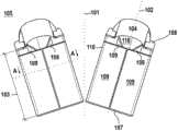
图1A示出了根据本文所描述的实施方式的坩埚组件的截面图;1A shows a cross-sectional view of a crucible assembly according to embodiments described herein;
图1B示出了根据本文所描述的实施方式的坩埚组件的截面图;Figure IB shows a cross-sectional view of a crucible assembly according to embodiments described herein;
图2示出了根据本文所描述的实施方式的坩埚的示意图;Figure 2 shows a schematic diagram of a crucible according to embodiments described herein;
图3A示出了根据本文所描述的实施方式的坩埚组件的示意性水平截面图;3A shows a schematic horizontal cross-sectional view of a crucible assembly according to embodiments described herein;
图3B示出了根据本文所描述的实施方式的第一冷却布置的示意性侧视图;Figure 3B shows a schematic side view of a first cooling arrangement according to embodiments described herein;
图4示出了根据本文所描述的实施方式的坩埚组件的布置的示意性俯视图;Figure 4 shows a schematic top view of an arrangement of crucible assemblies according to embodiments described herein;
图5示出了根据本文所描述的实施方式的沉积源的示意性透视图;Figure 5 shows a schematic perspective view of a deposition source according to embodiments described herein;
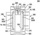
图6示出了根据本文所描述的另一实施方式的沉积源的示意性水平截面图;6 shows a schematic horizontal cross-sectional view of a deposition source according to another embodiment described herein;
图7示出了根据本文所描述的实施方式的用于在基板上沉积层的沉积系统的示意图;和7 shows a schematic diagram of a deposition system for depositing layers on a substrate in accordance with embodiments described herein; and
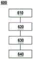
图8示出了根据本文所描述的实施方式的用于操作蒸发源的方法的流程图。8 shows a flowchart of a method for operating an evaporation source according to embodiments described herein.
具体实施方式Detailed ways
可详细参照本公开内容的各种实施方式,实施方式的一个或多个例子在附图中示出。在附图的以下描述中,相同的参考符号意指相同的部件。仅描述关于各个实施方式的差异。每一个例子通过作为本公开内容的解释而提供,并非用以限定本公开内容。此外,示出或描述为一个实施方式的一部分的特征可用于其他实施方式或与任何其他实施方式结合,以产生另一实施方式。说明书旨在包括此类修改和变化。Reference may be made in detail to various embodiments of the present disclosure, one or more examples of which are illustrated in the accompanying drawings. In the following description of the drawings, the same reference signs refer to the same parts. Only the differences with respect to the respective embodiments are described. Each example is provided as an explanation of the present disclosure and is not intended to limit the present disclosure. Furthermore, features illustrated or described as part of one embodiment can be used on or combined with any other embodiment to yield another embodiment. The description is intended to include such modifications and variations.
本公开内容的实施方式允许由于蒸发源的维护而导致的停工时间减少至少3倍(factor),具体是5倍或更多倍。目前已惊讶地发现,从数百摄氏度的温度至适用于维护的温度(例如室温)的蒸发源的冷却,受到坩埚温度与分配组件温度的温度差异的影响。相应地,共同蒸发源的冷却可能耗费6小时或更长时间,诸如10小时或更长时间。Embodiments of the present disclosure allow for a reduction in downtime due to maintenance of the evaporation source by a factor of at least 3, in particular a factor of 5 or more. It has now surprisingly been found that the cooling of the evaporation source from temperatures in the hundreds of degrees Celsius to temperatures suitable for maintenance (eg room temperature) is affected by the temperature difference between the crucible temperature and the distribution assembly temperature. Accordingly, cooling of the co-evaporation source may take 6 hours or more, such as 10 hours or more.
本公开内容的实施方式允许在2小时或更短的时间内,例如约1小时内进行蒸发源的冷却。因此,能够提供维护时间的显著减少。根据本公开内容的实施方式,提供一种冷却布置,例如额外的冷却布置。Embodiments of the present disclosure allow for cooling of the evaporative source in 2 hours or less, eg, about 1 hour. Thus, a significant reduction in maintenance time can be provided. According to embodiments of the present disclosure, a cooling arrangement, eg an additional cooling arrangement, is provided.
已知冷却元件(例如水冷式屏蔽件)是用于蒸发源之中,以减少热辐射至环绕蒸发源的区域。配置为减少蒸发源的热辐射的水冷式屏蔽件在减少系统的停工时间方面并非有效率的。因此,可与本文所描述的其他实施方式结合的本公开内容的实施方式提供配置用于主动冷却坩埚的冷却布置。本公开内容的实施方式促使对坩埚区域的冷却,例如通过对坩埚的内屏蔽件的气体冷却。Cooling elements, such as water-cooled shields, are known to be used in evaporation sources to reduce heat radiation to the area surrounding the evaporation source. Water-cooled shields configured to reduce thermal radiation from evaporation sources are not efficient in reducing system downtime. Accordingly, embodiments of the present disclosure, which may be combined with other embodiments described herein, provide cooling arrangements configured for actively cooling a crucible. Embodiments of the present disclosure facilitate cooling of the crucible region, such as by gas cooling of the inner shield of the crucible.
图1A示出了根据本公开内容的实施方式的坩埚组件100。坩埚组件100包括坩埚105的内壁110。提供加热单元120。加热单元120被配置为加热坩埚,用于进行待沉积材料的蒸发。根据一些实施方式,加热单元120可接触坩埚的壁。附加地或是可替代地,加热单元120可接触加热屏蔽件135。根据可与本文所描述的其他实施方式结合的一些实施方式,提供屏蔽布置140。屏蔽布置140包括一个或多个屏蔽件,例如两个或更多个屏蔽件。屏蔽布置被配置为减少坩埚的热辐射,例如至环绕坩埚的区域。根据一些实施方式,屏蔽布置140可包括多个屏蔽片。FIG. 1A shows a
根据本文所描述的实施方式,坩埚组件100包括位于坩埚105与屏蔽布置140之间的第一冷却布置130。举例而言,第一冷却布置130至少部分地环绕加热单元120。有利地,冷却(例如坩埚冷却)可被加强和/或增加。According to embodiments described herein, the
第一冷却布置130可附接至加热屏蔽件135或加热单元120。举例而言,第一冷却布置130可附接至加热单元120的背侧和/或加热屏蔽件135。第一冷却布置130可被配置为散逸来自加热单元和/或坩埚的热。因此,加热单元和/或坩埚可被主动冷却。The
加热单元的“背侧”可被理解为面对坩埚的对侧。因此,加热单元的背侧可被理解为背对坩埚内壁的侧面、或理解为面对坩埚环境的侧面。因此,加热单元的前侧面对坩埚,例如坩埚的内壁。加热单元的前侧可被主动加热。The "back side" of the heating unit can be understood as the opposite side facing the crucible. Thus, the back side of the heating unit can be understood as the side facing away from the inner wall of the crucible, or as the side facing the environment of the crucible. Therefore, the front side of the heating unit faces the crucible, eg the inner wall of the crucible. The front side of the heating unit can be actively heated.
根据可与本文所描述的其他实施方式结合的一实施方式,坩埚组件进一步包括第二冷却布置150。第二冷却布置可至少部分地环绕屏蔽布置140。具体地,第二冷却布置可环绕屏蔽布置以减少坩埚的热辐射至坩埚区域中,例如至真空腔室中。相邻于环绕坩埚的区域或位于环绕坩埚的区域中的元件的热负载被减少。According to an embodiment, which may be combined with other embodiments described herein, the crucible assembly further comprises a
根据一实施方式,坩埚组件被配置为提供至少0.1℃/s的冷却速率。因此,系统被配置为允许加速冷却。According to an embodiment, the crucible assembly is configured to provide a cooling rate of at least 0.1 °C/s. Therefore, the system is configured to allow accelerated cooling.
在本文所描述的实施方式中,加热单元120可以例如是一个或多个加热器。加热单元可至少沿着坩埚105的内壁110的一部分延伸。或者,加热单元可沿着坩埚105的超过一个内壁110延伸。In the embodiments described herein, the
根据本文的一些实施方式,坩埚组件可进一步包括屏蔽布置140。屏蔽布置140可被配置为将由加热单元120提供的热能反射回到坩埚105的内空间。根据本文的实施方式,屏蔽布置可支持蒸发坩埚105的内部容积内的有机材料的有效加热,和/或减少环绕坩埚的区域的热负载。According to some embodiments herein, the crucible assembly may further include a
屏蔽布置140可包括一个或多个屏蔽件。举例而言,屏蔽布置可包括两个屏蔽件。根据另一示例,屏蔽布置140可包括三个或更多个屏蔽件。屏蔽布置和/或屏蔽布置的屏蔽件可由反射热能的材料制成。举例而言,所述材料反射辐射。The shielding
根据本文所描述的实施方式,加热单元120可附接至、耦接至和/或集成在加热屏蔽件中,例如于加热屏蔽件的一侧。此外,第一冷却布置可附接至、耦接至和/或集成在加热屏蔽件中。举例而言,第一冷却布置可被提供在与加热单元的侧面相对的加热屏蔽的一侧。因此,在操作期间(亦即蒸发期间),加热屏蔽件被配置为接收来自加热单元120的热,用于将热分布于加热屏蔽件上,以及用于加热坩埚。为了进行维护,在主动冷却期间,加热屏蔽件用来吸收加热屏蔽件区域的热,用来散热至冷却介质。加热屏蔽件可用作散热器,以进行坩埚的主动冷却。According to embodiments described herein, the
图1B示出了坩埚组件100的另一实施方式。因此,加热单元120凸出至坩埚105的内部容积中。因此,可实现恒定的热分布。加热单元120可从坩埚的底侧引入。FIG. 1B shows another embodiment of a
根据可与本文所描述的其他实施方式结合的一些实施方式,坩埚组件的加热单元可布置在坩埚的内部容积内。举例而言,加热单元120可包括一个或多个中央加热元件。图1B示出了中央加热元件。中央加热元件和第二中央加热元件可分别包括导体以提供电力至中央加热元件。根据可与本文所描述的其他实施方式结合的实施方式,可提供超过一个中央加热元件。举例而言,可提供两个或更多个中央加热元件。According to some embodiments, which may be combined with other embodiments described herein, the heating unit of the crucible assembly may be arranged within the interior volume of the crucible. For example,
图2示出了根据本文所描述的另一实施方式的坩埚105。坩埚是分成两部分进行说明,此两部分相对于对称平面101是镜像对称。坩埚105可包括一个或多个传热元件109,传热元件109从壁凸出至坩埚105的内部容积104中。具体地,一个或多个传热元件可从侧壁凸出至坩埚的内部容积中。Figure 2 shows a
图2所示的坩埚105可包括底壁107和顶壁108,底壁107和顶壁108通过侧壁110彼此连接。坩埚105的内部容积116可分别被底壁107、顶壁108和侧壁110或侧壁的个别部分所围绕。坩埚105可包括开口104,开口104允许蒸发源材料从坩埚离开并进入分配组件。具体地,坩埚的开口可连接至分配组件,此分配组件将蒸发源材料导引至基板。The
坩埚105与分配组件可通过外形配合的连接件彼此连接。根据本文所描述的实施方式,在坩埚与分配组件之间的连接件可附加地或是可替代地包括凸缘单元。坩埚105与分配组件可提供为分离的单元,此分离的单元可以是分离的并且在凸缘单元处连接或组装,例如用于蒸发源的操作。The
在本公开内容中,“沉积源和/或蒸发源”可被理解为配置用于提供待沉积在基板上的材料源的装置或组件。具体地,沉积源200可被理解为具有坩埚组件100和分配组件220(例如参见图5)的装置或组件,坩埚组件100配置为蒸发待沉积的材料,分配组件220配置用于将蒸发材料提供至基板10。因此,沉积源也可被称作本文的蒸发源。表述“分配组件配置用于将蒸发材料提供至基板”可被理解为,分配组件被配置用于在沉积方向上导引蒸发的或气态的源材料,如图6所例示的离开一个或多个出口225的蒸发材料的羽流。因此,气态的源材料(例如用于沉积有机发光二极管装置的薄膜的材料)是在分配组件内被导引且通过一个或多个出口225离开分配组件。In the present disclosure, "deposition source and/or evaporation source" may be understood as a device or assembly configured to provide a source of material to be deposited on a substrate. In particular,
在本公开内容中,“坩埚”可被理解为具有储存器的装置,用于通过加热坩埚以进行材料的蒸发。因此,“坩埚”可被理解为源材料储存器,其可被加热以通过源材料的蒸发和升华的至少一者来将此源材料蒸发为气体。典型地,坩埚包括加热器,以将坩埚中的源材料蒸发为气态的源材料。举例而言,待蒸发的初始材料可以是粉末形式。储存器可具有内部容积以接收待蒸发的源材料,例如有机材料。举例而言,坩埚的体积可以是在100cm3与3000cm3之间,具体地是700cm3与1700cm3之间,更具体地是1200cm3。具体地,坩埚可包括加热单元,所述加热单元配置用于加热提供在坩埚的内部容积中的源材料,加热至源材料会蒸发的温度。举例而言,坩埚可以是用于蒸发有机材料的坩埚,例如具有约100℃至约600℃的蒸发温度的有机材料。In this disclosure, a "crucible" may be understood as a device having a reservoir for the evaporation of material by heating the crucible. Thus, a "crucible" can be understood as a source material reservoir that can be heated to vaporize the source material into a gas by at least one of evaporation and sublimation of the source material. Typically, the crucible includes a heater to vaporize the source material in the crucible to a gaseous source material. For example, the starting material to be evaporated may be in powder form. The reservoir may have an interior volume to receive source material, eg, organic material, to be evaporated. For example, the volume of the crucible may be between 100 cm3 and 3000 cm3 , specifically between 700 cm3 and 1700 cm3 , more specifically 1200 cm3 . In particular, the crucible may comprise a heating unit configured to heat the source material provided in the interior volume of the crucible to a temperature at which the source material will evaporate. For example, the crucible may be a crucible for evaporating organic materials, such as organic materials having an evaporation temperature of about 100°C to about 600°C.
根据本文的实施方式,图2所示的坩埚105可包括布置在坩埚100的内部容积116内的一个或多个传热元件109。传热元件109被配置为提供坩埚的内部容积的间接加热。在本文所描述的实施方式中,来自一个或多个传热元件109的热可以直接提供至坩埚105的内部容积116内的源材料,此源材料可以是粉末、液体和/或颗粒状的形式。在本文所描述的实施方式中,传热元件可被配置为被动地接收热,且可以不需要直接连接至例如是加热单元和/或电源。举例而言,图2所示的坩埚可以是图1A所示的坩埚组件的一部分。According to embodiments herein, the
根据本文的实施方式,传热元件109可以例如是接收来自壁和/或来自坩埚外部的热。在有机发光二极管沉积工艺期间,来自壁和/或来自坩埚外部的热是通过传热元件109分布在坩埚的内部容积内,以确保更均匀的加热以及源材料的后续蒸发。根据本文所描述的一些实施方式,传热元件被布置在坩埚的内部容积内,以使坩埚的内部容积内的任何特定位置所测量的温度,相较于预定温度和/或相较于坩埚的内部容积内的另一特定位置的温度,最大温差是10℃或更小,例如是5℃或更小,诸如0.5℃至3℃。再者,附加地或是可替代地,此最大温差可以是4%或更小,例如2%或更小,诸如0.2%至1.1%。在图2所示的实施方式中,传热元件109从壁凸出至坩埚105的内部容积116中。传热元件可以是杯状,以容纳液体。根据本文的实施方式,此液体可以是源材料。According to embodiments herein, the
根据本文的一些实施方式,一个或多个传热元件可由包括具有高热传导性的金属或合金的材料制成。根据所使用的源材料的蒸发温度,一个或多个传热元件的材料应至少在高达源材料的蒸发温度下是稳定且惰性的,此蒸发温度可以例如是在150℃与650℃或更高温度之间的任何温度。According to some embodiments herein, one or more of the heat transfer elements may be fabricated from materials including metals or alloys with high thermal conductivity. Depending on the evaporation temperature of the source material used, the material of the heat transfer element or elements should be stable and inert at least up to the evaporation temperature of the source material, which may for example be between 150°C and 650°C or higher any temperature in between.
根据本文的实施方式,任何一个或多个传热元件109可在平行于坩埚105的中心轴102的纵向方向上延伸至坩埚105的内部容积116的总长度103的约0%至约100%的任何地点。举例而言,任何一个或多个传热元件可延伸至坩埚的内部容积的总长度的至少约90%。According to embodiments herein, any one or more
图3A示出了根据本文所描述的实施方式的坩埚组件的示意性水平截面图。根据可与本文所描述的任何其他实施方式结合的一些实施方式,坩埚组件100包括屏蔽布置140。3A shows a schematic horizontal cross-sectional view of a crucible assembly in accordance with embodiments described herein. According to some embodiments, which may be combined with any of the other embodiments described herein, the
如图3A所例示的,屏蔽布置140可包括屏蔽板堆叠。举例而言,屏蔽板堆叠可包括两个或更多个屏蔽板。具体地,屏蔽布置可包括两个或更多个被动辐射屏蔽件。具体地,两个或更多个屏蔽板可被配置用于将由加热单元120所提供的热能反射回到坩埚110的内壁。举例而言,屏蔽板可具有0.1mm至3mm的厚度。此外,屏蔽板的材料可选自由铁质材料或非铁质材料构成的组中的至少一材料,例如是选自由不锈钢、铜(Cu)、铝(A1)、铜合金、铝合金、黄铜、铁、钛(Ti)、陶瓷和其他合适材料构成的组中的至少一材料。As illustrated in Figure 3A, the shielding
根据可与本文所描述的任何其他实施方式结合的一些实施方式,可以一间距S来堆叠两个或更多个屏蔽板,0.1mm≤S≤1.0mm,例如在邻近的屏蔽板之间的间距可以是0.3mm。According to some embodiments, which may be combined with any of the other embodiments described herein, two or more shielding plates may be stacked with a spacing S, 0.1 mm≤S≤1.0 mm, such as the spacing between adjacent shielding plates Can be 0.3mm.
举例而言,屏蔽布置140可通过使用第二冷却布置150被冷却,第二冷却布置150可接触屏蔽布置。第二冷却布置可包括冷却沟道152。冷却沟道可在实质上垂直平面上和/或在实质上水平平面上定向。For example, the shielding
冷却流体可流经冷却沟道。冷却流体可以例如是水。提供从坩埚组件至冷却流体的热传递。具体地,由屏蔽布置所散发的热被冷却流体吸收。辐射至坩埚组件的外部区域的坩埚组件的热可通过热传导和/或热辐射散逸。A cooling fluid may flow through the cooling channels. The cooling fluid can be, for example, water. Provides heat transfer from the crucible assembly to the cooling fluid. Specifically, the heat dissipated by the shielding arrangement is absorbed by the cooling fluid. The heat of the crucible assembly radiated to the outer regions of the crucible assembly may be dissipated by thermal conduction and/or thermal radiation.
举例而言,第二冷却布置150可以是水冷式冷却布置。流体可以是包括水、压缩空气、压缩的干燥空气、氦、氢、氮、或任何其他适合的冷却组分或它们的组合的组中的一者。具体地,冷却流体可以是压缩的干燥空气。For example, the
因此,当通过使用第二冷却布置150来冷却屏蔽布置140时,由于屏蔽布置将坩埚与第二冷却布置隔离,因此使用第二冷却布置的坩锅的冷却是无效率的。Therefore, when the
根据本文所描述的实施方式,提供第一冷却布置130。第一冷却布置提供在屏蔽布置140与坩埚之间。第一冷却布置130可包括冷却沟道134,冷却沟道134与关于第二冷却布置所描述的冷却沟道类似。第一冷却布置的冷却沟道可在实质上水平平面上和/或实质上垂直平面上布置。According to the embodiments described herein, a
本文所使用的“实质上水平”可被理解为水平定向,可从相对于垂直定向的90和/或270度角偏离±15度,具体地是±10度,更具体地是±5度。本文所使用的“实质上垂直”可被理解为垂直定向,可从相对于水平定向的0和/或180度角偏离±15度,具体地是±10度,更具体地是±5度。As used herein, "substantially horizontal" may be understood as a horizontal orientation that may deviate ±15 degrees, specifically ±10 degrees, more specifically ±5 degrees, from an angle of 90 and/or 270 degrees relative to a vertical orientation. As used herein, "substantially vertical" may be understood as a vertical orientation, which may be ±15 degrees, specifically ±10 degrees, more specifically ±5 degrees, from an angle of 0 and/or 180 degrees relative to a horizontal orientation.
第一冷却布置130可附接至加热单元120和/或加热屏蔽件。举例而言,第一冷却布置是直接接触于加热单元和/或加热屏蔽件。加热屏蔽件可被视为加热单元的一部分。第一冷却布置可以是直接接触于加热单元120的加热屏蔽件135。举例而言,第一冷却布置可附接至加热屏蔽件135。The
有利地,第一冷却布置130提供冷却至加热单元和/或附加的(attached)加热屏蔽件。因此,可以提供坩埚的冷却。具体地,可以提供坩埚内壁的冷却。更具体地,通过建立坩埚与第一冷却布置之间的热传导和/或辐射来促进从坩埚到第一冷却布置的热传递。有利地,热可通过冷却沟道被有效地散逸。Advantageously, the
关于图1B的实施方式,延伸至坩埚内部容积中的加热单元可被冷却。因此,坩埚亦可从内部被冷却。举例而言,延伸至坩埚内部容积中的加热元件可被第一冷却布置冷却。因此,来自坩埚内部容积的热传递可被增强。举例而言,促进了从坩埚内部容积经由冷却的加热单元向第一冷却布置的散热。With regard to the embodiment of Figure IB, the heating unit extending into the interior volume of the crucible may be cooled. Therefore, the crucible can also be cooled from the inside. For example, heating elements extending into the interior volume of the crucible may be cooled by the first cooling arrangement. Thus, heat transfer from the inner volume of the crucible can be enhanced. For example, heat dissipation from the crucible interior volume via the cooled heating unit to the first cooling arrangement is facilitated.
根据本文所描述的实施方式,第一冷却布置可使用流体来进行冷却。流体可以是包括水、压缩空气、压缩的干燥空气、氦、氢、氮、或任何其他合适的冷却组分或它们的组合的组中的一者。具体地,冷却流体可以是压缩的干燥空气。因此,可进一步增强坩埚组件内的增加的散热。According to embodiments described herein, the first cooling arrangement may use a fluid for cooling. The fluid may be one of the group comprising water, compressed air, compressed dry air, helium, hydrogen, nitrogen, or any other suitable cooling component or combination thereof. Specifically, the cooling fluid may be compressed dry air. Thus, increased heat dissipation within the crucible assembly can be further enhanced.
根据关于图3B的实施方式,示出了具有第一冷却布置130的坩埚105。第一冷却布置可被布置在加热单元120或加热单元的加热屏蔽件处。第一冷却布置可包括一个或多个冷却沟道134。举例而言,关于图3B,第一冷却布置可包括两个或更多个冷却沟道134,具体地是三个或更多个冷却沟道134。冷却沟道134可连接至一个或多个冷却管132。冷却管132可被配置用于排放第一冷却布置130的冷却流体。According to the embodiment with respect to Fig. 3B, the
举例而言,排放的冷却流体可通过热交换元件(未示出)。因此,冷却流体带走坩埚组件的热。排放的流体的冷却并不限于使用热交换元件。For example, the discharged cooling fluid may pass through a heat exchange element (not shown). Thus, the cooling fluid removes heat from the crucible assembly. Cooling of the discharged fluid is not limited to the use of heat exchange elements.
各个冷却沟道134可以具有不同的尺寸。冷却沟道134的尺寸可受各种参数的影响,例如坩埚的尺寸和/或流经冷却沟道134的冷却流体的量。举例而言,冷却沟道可包括约200cm的长度和约0.7cm的内径,例如用于将气体用作冷却流体。第一冷却布置的冷却沟道可由包括铜(Cu)、钛、不锈钢、铝、钼(Mo)、钽(Ta)的组中的材料制成。The
因此,本公开内容所描述的实施方式有利地提供将蒸发源从操作温度冷却至约100℃的温度的的减少的冷却时间。本公开内容的实施方式具有生产的停工时间可被减少的优点。具体地,相较于传统的坩埚组件,本文所描述的实施方式有助于提供1小时或更短的冷却时间来进行从500℃至600℃的操作温度下降至约100℃的温度的冷却。与之相反,使用传统的冷却方法,从500℃至600℃的操作温度下降至约100℃的温度的冷却时间可以大约是8小时或更长时间。因此,相较于传统已知的方法,本文所描述的本公开内容的实施方式提供显著减少的冷却时间。Accordingly, the embodiments described in this disclosure advantageously provide reduced cooling time for cooling the evaporation source from an operating temperature to a temperature of about 100°C. Embodiments of the present disclosure have the advantage that production downtime may be reduced. Specifically, the embodiments described herein help provide a cooling time of 1 hour or less for cooling from operating temperatures of 500°C to 600°C down to temperatures of about 100°C compared to conventional crucible assemblies. In contrast, using conventional cooling methods, the cooling time from an operating temperature of 500°C to 600°C to a temperature of about 100°C can be about 8 hours or more. Accordingly, the embodiments of the present disclosure described herein provide significantly reduced cooling times as compared to conventionally known methods.
图4示出了根据可与其他实施方式结合的本文所描述的实施方式的坩埚组件100的布置。举例而言,图4示出了包括至少三个坩埚组件100的蒸发组件400的一部分。根据本文的一些实施方式,蒸发组件400可包括任何根据本文所描述的实施方式的多个坩埚。举例而言,蒸发组件可包括二、三、四或更多个坩埚,这些坩埚可连接到至少一个或多个分配组件。举例而言,三个对准的坩埚组件可以连接至图6所示的分配组件。根据可与本文所描述的其他实施方式结合的实施方式,坩埚的截面可具有如图4所例示的三角形,或者可具有另一形状,诸如圆形、椭圆形或另一多边形。FIG. 4 illustrates an arrangement of
蒸发组件可包括共同外部冷却布置151。共同外部冷却布置可沿着相应的蒸发组件的两个或更多个坩埚组件100延伸。因此,蒸发组件的有效结合冷却是可能的。共同外部冷却布置可取代蒸发组件400的单一坩埚组件的第二冷却布置。或者,共同外部冷却布置可以是蒸发组件400和/或坩埚组件100的额外的冷却源。The evaporative assembly may include a common
图5示出了根据本文所描述的实施方式的沉积源200。沉积源200包括坩埚组件100,具体地是蒸发坩埚。蒸发坩埚被配置为蒸发待沉积于基板上的材料。此外,沉积源200包括分配组件220,分配组件220可以是细长管。分配组件可包括一个或多个出口225。举例而言,一个或多个出口225可以是喷嘴。典型地,喷嘴被配置用于将蒸发材料的羽流导向至基板10。分配组件220可以是流体连通于坩埚组件100。举例而言,沉积源200可包括阀,所述阀配置为控制蒸发材料从坩埚组件100流动至分配组件220。举例而言,阀可以是关闭的,以停止蒸发材料从坩埚流动至分配组件。FIG. 5 shows a
如图5所例示的,分配组件220可被设计为三角形。在两个或更多个分配组件彼此相邻布置的情况下,三角形分配组件可以是有利的,如参照图4和/或图6更详细地示例性描述的。具体地,三角形分配组件220能够使邻近的分配组件(例如,分配组件)的出口尽可能地接近彼此。如此允许达到来自不同分配组件的不同材料的改善的混合物,例如对于二、三或甚至更多种不同材料的共蒸发的情况。As illustrated in Figure 5, the dispensing
如图5所例示的,分配组件220可包括壁,例如侧壁221和背侧壁222,使得在分配组件的内部提供内部中空空间。此外,可提供加热单元223以加热分配组件。加热单元可被安装或附接至分配组件的壁。加热单元223可与针对坩埚组件所描述的加热单元120类似。As illustrated in Figure 5, the dispensing
因此,分配组件220可被加热至由蒸发坩埚所提供的有机材料的蒸气不会在分配组件220的壁的内部凝结的温度。此外,如图5所例示的,沉积源200可包括屏蔽装置224,具体地是成型屏蔽装置,以定界提供至基板的蒸发材料的分配锥。具体地,屏蔽装置可被配置为减少朝向沉积区的热辐射。此外,屏蔽装置可通过第三冷却布置227冷却。举例而言,第三冷却元件227可被安装至屏蔽装置224的背侧,且可包括用于冷却流体的一个或多个冷却沟道或导管。Thus, the
在本公开内容中,“分配组件”可被理解为配置用于从分配组件向基板提供蒸发材料的组件,具体地是从分配组件向基板提供蒸发材料的羽流。举例而言,分配组件可包括可以是细长管的分配组件。举例而言,本文所描述的分配组件可提供具有多个开口和/或喷嘴的线源,这些开口和/或喷嘴沿着分配组件的长度布置成至少一条线。举例而言,分配组件可以由钛制成。In the present disclosure, a "distribution assembly" may be understood as an assembly configured to provide evaporative material from the distribution assembly to the substrate, in particular a plume of evaporative material from the distribution assembly to the substrate. For example, the dispensing assembly may include a dispensing assembly that may be an elongated tube. For example, the dispensing assemblies described herein may provide a line source having a plurality of openings and/or nozzles arranged in at least one line along the length of the dispensing assembly. For example, the dispensing assembly may be made of titanium.
因此,分配组件可以是线性分配喷头,例如具有设置在其中的多个开口(或细长狭缝)。此外,分配组件可典型地具有内空间、中空空间或管,其中蒸发材料可被提供或导引,例如从蒸发坩埚至基板。根据可与本文所描述的任何其他实施方式结合的实施方式,分配组件的长度可至少对应于待沉积基板的高度。具体地,分配组件的长度可以比待沉积基板的高度长至少10%或甚至20%。举例而言,分配组件的长度可以是1.3m或更长,例如2.5m或更长。因此,可提供在基板上端和/或基板下端的均匀沉积。根据另一配置,分配组件可包括一个或多个点源,这些点源可沿着垂直轴布置。Thus, the dispensing assembly may be a linear dispensing spray head, eg, having a plurality of openings (or elongated slits) disposed therein. Furthermore, the distribution assembly may typically have an inner space, hollow space or tube in which the evaporation material may be provided or directed, eg from the evaporation crucible to the substrate. According to an embodiment, which may be combined with any of the other embodiments described herein, the length of the dispensing assembly may correspond at least to the height of the substrate to be deposited. In particular, the length of the distribution assembly may be at least 10% or even 20% longer than the height of the substrate to be deposited. For example, the length of the dispensing assembly may be 1.3 m or more, such as 2.5 m or more. Thus, uniform deposition at the upper end of the substrate and/or at the lower end of the substrate can be provided. According to another configuration, the dispensing assembly may include one or more point sources, which may be arranged along a vertical axis.
因此,本文所描述的“分配组件”可被配置为提供实质上垂直延伸的线源。在本公开内容中,术语“实质上垂直”被具体理解为,在提及基板定向时,允许10°或更小的垂直方向的偏差。可以提供此偏差,因为具有从垂直定向的一些偏差的基板支撑件可能导致更稳定的基板位置。此外,在有机材料的沉积期间,基板定向被视为实质上垂直,这被认为不同于水平基板定向。因此,可通过在对应于一个基板尺寸的一个方向上延伸的线源、以及沿着对应于其他基板尺寸的其他方向的平移运动来涂布基板的表面。Accordingly, the "distribution assemblies" described herein may be configured to provide a substantially vertically extending line source. In the present disclosure, the term "substantially vertical" is specifically understood to allow a deviation of 10° or less from vertical when referring to substrate orientation. This deviation can be provided because a substrate support with some deviation from vertical orientation may result in a more stable substrate position. Furthermore, during deposition of the organic material, the substrate orientation is considered to be substantially vertical, which is considered to be different from the horizontal substrate orientation. Thus, the surface of a substrate may be coated by a line source extending in one direction corresponding to one substrate dimension, and translational motion in other directions corresponding to other substrate dimensions.
分配组件亦可包括加热单元,促进从坩埚导引至基板的蒸发材料的精确的温度控制。一个或多个热屏蔽件亦可被提供在分配组件附近。一个或多个热屏蔽件可减少来自蒸发组件的能源损耗,可减少涂布/制造工艺期间的总能量消耗。The distribution assembly may also include a heating unit to facilitate precise temperature control of the evaporated material directed from the crucible to the substrate. One or more thermal shields may also be provided adjacent to the distribution assembly. One or more thermal shields can reduce energy losses from the evaporation assembly, which can reduce overall energy consumption during the coating/manufacturing process.
根据可与本文所描述的其他实施方式结合的实施方式,沉积源200可包括用于测量温度的温度传感器226。附加地或是可替代地,温度传感器可被布置和配置为用于测量分配组件和/或坩埚组件的温度。According to embodiments, which may be combined with other embodiments described herein,
温度传感器226与控制器229连接。控制器229可被配置为确定以及显示蒸发源的温度。具体地,温度可在蒸发源的不同区域处进行测量。甚至更具体地,温度可在分配组件和坩埚组件处进行测量。The
控制器229更进一步允许第一冷却布置、第二冷却布置和/或第三冷却布置的调节。举例而言,可以调节一个或多个冷却布置的温度。每个冷却布置可单独地调节。举例而言,分配源的第三冷却布置可被调节为,不同于坩埚组件的第一冷却布置和第二冷却布置的温度。The
根据可与本文的其他实施方式结合的实施方式,从坩埚组件与分配组件比较而言,蒸发源的温度可以不同。举例而言,分配组件的温度高于坩埚组件的温度。因此,当分配组件和坩埚组件皆被冷却时,防止了蒸发材料的凝结。因此,坩埚的主动冷却防止了分布管的加热,特别是在降温时间周期期间,例如在准备维护期间。According to embodiments that may be combined with other embodiments herein, the temperature of the evaporation source may be different from the crucible assembly compared to the distribution assembly. For example, the temperature of the distribution assembly is higher than the temperature of the crucible assembly. Thus, condensation of the evaporative material is prevented when both the distribution assembly and the crucible assembly are cooled. Thus, active cooling of the crucible prevents heating of the distribution pipe, especially during cool down time periods, such as during preparation for maintenance.
根据本文所描述的实施方式,可能发生蒸发源的停止,例如由于真空腔室的维护等。当蒸发源被停止(可通过关闭加热单元实现),坩埚的内部容积的温度可维持在高水平。举例而言,加热的材料辐射了可能无法直接被散逸的热能。因此,刚刚关闭加热单元之后,材料仍然可被蒸发。蒸发材料仍然可上升至分配组件。根据实施方式,通过调节分配组件和坩埚组件的温度,可防止蒸发材料的凝结。According to the embodiments described herein, stoppage of the evaporation source may occur, for example due to maintenance of the vacuum chamber or the like. When the evaporation source is stopped (which can be achieved by turning off the heating unit), the temperature of the inner volume of the crucible can be maintained at a high level. For example, heated material radiates thermal energy that may not be dissipated directly. Therefore, the material can still be evaporated just after the heating unit is switched off. Evaporated material can still rise to the dispensing assembly. According to an embodiment, by adjusting the temperature of the distribution assembly and the crucible assembly, condensation of the evaporation material can be prevented.
根据实施方式,分配组件和坩埚组件的温度调节可取决于彼此来提供。根据实施方式,可通过控制器来调节温度。此外,温度的调节可包括至少部分的蒸发源(例如是分配组件和/或坩埚组件)的加热和/或冷却。According to embodiments, temperature regulation of the distribution assembly and the crucible assembly may be provided in dependence on each other. According to an embodiment, the temperature may be adjusted by a controller. Additionally, the adjustment of the temperature may include heating and/or cooling of at least a portion of the evaporation source (eg, the distribution assembly and/or the crucible assembly).
举例而言,若蒸发源的温度被冷却至100℃,分配组件的温度可在冷却期间维持高于坩埚组件的温度。举例而言,分配组件的温度可维持高于冷却期间的坩埚组件的温度+10℃或更高,具体地是+30℃、50℃或更高,例如是约+20℃。可以通过流经冷却沟道和/或冷却管的冷却流体的温度,和/或通过调整相关加热器的功率水平,来提供温度差。For example, if the temperature of the evaporation source is cooled to 100°C, the temperature of the distribution assembly can be maintained above the temperature of the crucible assembly during cooling. For example, the temperature of the distribution assembly may be maintained +10°C or higher above the temperature of the crucible assembly during cooling, in particular +30°C, 50°C or higher, eg about +20°C. The temperature difference may be provided by the temperature of the cooling fluid flowing through the cooling channels and/or cooling tubes, and/or by adjusting the power level of the associated heater.
图6示出了根据本文所描述的另一实施方式的沉积源的示意性水平截面图。具体地,图6示出了包括第一分配组件220A、第二分配组件220B和第三分配组件220℃的沉积源200的截面俯视图。因此,通过提供三个对应的蒸发坩埚,材料沉积布置可被提供为蒸发源阵列,例如其中多于一种材料可在相同时间被蒸发。Figure 6 shows a schematic horizontal cross-sectional view of a deposition source according to another embodiment described herein. Specifically, FIG. 6 shows a cross-sectional top view of a
具体地,如图6所例示的,根据可与本文所描述的任何其他实施方式结合的实施方式,第一分配组件220A、第二分配组件220B和第三分配组件220C可被配置为具有垂直于分配组件的长度的实质上三角形截面的分配组件。具有三个分配组件的沉积源亦可称作三源。Specifically, as illustrated in FIG. 6, according to an embodiment that may be combined with any of the other embodiments described herein, the
例示性地参照图6,三源可提供有冷却屏蔽件228。冷却屏蔽件228可包括侧壁228A,侧壁228A被布置成使U形冷却屏蔽件被提供以减少朝向沉积区(亦即基板)的热辐射。举例而言,冷却屏蔽件可被提供为具有用于冷却流体(诸如水)的导管的金属板,此导管附接至金属板或提供于金属板中。附加地或是可替代地,可提供热电式冷却装置或其他冷却装置,以对冷却屏蔽件进行冷却。Referring illustratively to FIG. 6 , the three sources may be provided with cooling shields 228 . The
在图6中,为了说明的目的,离开分配组件的出口225的蒸发源材料以箭头所标示。由于实质上三角形的分配组件,源自于三个分配组件的蒸发锥彼此接近,使来自不同分配组件的源材料的混合可得以改善。具体地,分配组件的截面形状允许邻近的分配组件的出口或喷嘴彼此接近。In Figure 6, the evaporation source material exiting the
如图6进一步所示出的,具体地是成型屏蔽装置的屏蔽装置224可被提供为例如附接至冷却屏蔽件228或作为冷却屏蔽件的一部分。通过提供成型屏蔽件,可以控制通过出口离开分配组件或管的蒸气的方向,亦即可以减小蒸气排放的角度。根据一些实施方式,通过出口或喷嘴提供的至少一部分的蒸发材料被成型屏蔽件阻挡。因此,可以控制排放角度的宽度。As further shown in FIG. 6 , a
例示性地参照图7,描述根据本公开内容的用于蒸发沉积材料的沉积系统300。根据可与本文描述的任何其他实施方式结合的实施方式,沉积系统包括沉积腔室370,具体地是真空沉积腔室。在如图7所示的沉积系统300的实施方式中,沉积系统300包括真空沉积腔室中的根据本文所描述的任何实施方式的沉积源200(或蒸发源)和用于对蒸发的沉积材料进行沉积的分配组件。此外,沉积源可包括如本文的实施方式中所描述的坩埚组件100和分配组件220。分配组件220可进一步包括加热单元。Referring illustratively to FIG. 7, a
根据可与本文描述的任何其他实施方式结合的一些实施方式,沉积腔室是“真空沉积腔室”。在本公开内容中,“真空沉积腔室”可被理解为配置用于真空沉积的腔室。本文所使用的术语“真空”在技术真空的意义上可被理解为具有小于例如是10毫巴(mbar)的真空压力。典型地,如本文所描述的真空腔室中的压力可以是在约10-5毫巴与约10-8毫巴之间,更典型地在约10-5毫巴与约10-7毫巴之间,甚至更典型地在约10-6毫巴与约10-7毫巴之间。根据一些实施方式,真空腔室中的压力可被视为真空腔室内的蒸发材料的分压或总压(当只有蒸发材料是作为待沉积在真空腔室中的组分而存在时,分压与总压可以大约相同)。在一些实施方式中,真空腔室的总压可以是从约10-4毫巴至约10-7毫巴,尤其是在除蒸发材料之外的第二组分存在于真空腔室中的情况下(诸如气体或类似物)。According to some embodiments, which may be combined with any of the other embodiments described herein, the deposition chamber is a "vacuum deposition chamber". In the present disclosure, a "vacuum deposition chamber" may be understood as a chamber configured for vacuum deposition. The term "vacuum" as used herein may be understood in the sense of a technical vacuum as having a vacuum pressure of less than, for example, 10 millibars (mbar). Typically, the pressure in a vacuum chamber as described herein may be between about10-5 mbar and about10-8 mbar, more typically between about10-5 mbar and about10-7 mbar between, even more typically, between about10-6 mbar and about10-7 mbar. According to some embodiments, the pressure in the vacuum chamber can be considered as the partial pressure or the total pressure of the evaporation material in the vacuum chamber (the partial pressure when only the evaporation material is present as a component to be deposited in the vacuum chamber can be about the same as the total pressure). In some embodiments, the total pressure of the vacuum chamber may be from about10-4 mbar to about10-7 mbar, especially where a second component other than the evaporation material is present in the vacuum chamber down (such as gas or the like).
此外,如图7所例示的,沉积源200可被提供在轨道或线性导件(1inear guide)364上。线性导件364可被配置用于沉积源200的平移运动。此外,可以提供用于提供沉积源200的平移运动的驱动器。具体地,用于材料沉积布置源的非接触传送的传送设备可被提供在真空沉积腔室中。Furthermore, as illustrated in FIG. 7 , the
根据本文所描述的实施方式,沉积腔室的区域可被保护,免于过热(overheating)。举例而言,基板支撑件360、基板和/或掩模363可被保护,免受可能从蒸发源所散发的热能的影响。According to embodiments described herein, areas of the deposition chamber can be protected from overheating. For example,
如图7所例示的,沉积腔室370可具有闸阀365,真空沉积腔室可通过闸阀365连接至相邻的路由模块或相邻的服务模块。典型地,路由模块被配置为传送基板至另一真空沉积系统以进行进一步处理,服务模块被配置用于沉积源的维护。具体地,闸阀允许至相邻的真空腔室的真空密封,例如相邻的路由模块或相邻的服务模块的真空腔室,闸阀可以开启和关闭以移动基板和/或掩模进入或离开真空沉积系统。As illustrated in FIG. 7,
例示性地参照图7,根据可与本文所描述的任何其他实施方式结合的实施方式,两个基板,例如第一基板10A和第二基板10B,可被支撑在沉积腔室370内的相应传送轨道上。此外,可以提供用于在其上提供掩模363的两个轨道。具体地,用于基板载体和/或掩模载体的传送的轨道可提供有用于载体的非接触传送的另一传送设备。Referring illustratively to FIG. 7 , according to an embodiment, which may be combined with any of the other embodiments described herein, two substrates, eg, a first substrate 10A and a second substrate 10B, may be supported in respective transfers within the
典型地,基板的涂布可包括通过相应的掩模来掩蔽基板,例如通过边缘排除掩模或通过阴影掩模。根据典型的实施方式,掩模,例如对应于第一基板10A的第一掩模363A和对应于第二基板10B的第二掩模363B,被提供在掩模框架362中,以将相应的掩模保持在预定位置中,如图7所例示的。Typically, coating of the substrate may involve masking the substrate by means of a corresponding mask, eg by an edge exclusion mask or by a shadow mask. According to typical embodiments, masks, such as a first mask 363A corresponding to the first substrate 10A and a
如图7所示,线性导件364提供沉积源200的平移运动的方向。在沉积源200的两侧上,可提供掩模363,例如用于掩蔽第一基板10A的第一掩模363A以及用于掩蔽第二基板10B的第二掩模363B。各个掩模可实质上平行于沉积源200的平移运动的方向延伸。此外,在沉积源的相对侧的基板亦可实质上平行于平移运动的方向延伸。As shown in FIG. 7 ,
例示性地参照图7,可以提供配置用于沿着线性导件364的沉积源200的平移运动的源支撑件361。典型地,源支撑件361支撑坩埚组件100以及提供在坩埚组件上的分配组件220,如图7所示意性示出的。因此,产生于蒸发坩埚中的蒸气可向上移动并离开分配组件的一个或多个出口。因此,如本文所描述的,分配组件被配置用于从分配组件220至基板10提供蒸发材料,具体地是蒸发的有机材料的羽流。Referring illustratively to FIG. 7 , a
关于图8以及根据本文所描述的实施方式,描述用于操作沉积源的方法600。With respect to FIG. 8 and in accordance with embodiments described herein, a
根据可与本文描述的任何其他实施方式结合的一些实施方式,操作蒸发源的方法包括,加热坩埚以蒸发材料(方块610)以及关闭蒸发源(方块620)。举例而言,关闭蒸发源包括,关闭加热(方块630)。此外,关闭蒸发源可包括主动冷却坩埚(方块640)。According to some embodiments, which may be combined with any of the other embodiments described herein, the method of operating an evaporation source includes heating a crucible to evaporate material (block 610 ) and turning off the evaporation source (block 620 ). For example, turning off the evaporation source includes turning off the heating (block 630). Additionally, turning off the evaporation source may include actively cooling the crucible (block 640).
根据本公开内容的实施方式,关闭蒸发源可包括关闭加热单元120和/或加热单元223。可断开到坩埚的热供应。根据可与本文描述的任何其他实施方式结合的另一实施方式,关闭蒸发源可包括主动冷却坩埚。主动冷却坩埚可包括开启第一冷却布置130。冷却流体可通过冷却沟道。冷却流体可接着提供冷却。举例而言,加热单元可被冷却。此外,坩埚和/或坩埚的内壁可被冷却。此外,蒸发材料可被冷却。According to an embodiment of the present disclosure, turning off the evaporation source may include turning off the
根据本文所描述的实施方式,蒸发源可包括分配组件,此蒸发源可以例如是通过方法600来操作。分配组件可包括加热单元223。分配组件的温度可通过加热单元来调节。According to embodiments described herein, an evaporation source may include a dispensing assembly, which may be operated by
根据一些实施方式,方法600进一步包括:调节坩埚的温度,以使分配组件的温度高于坩埚的温度。分配组件可包括关于其他实施方式所描述的加热单元。此外,坩埚组件和/或分配组件可包括冷却布置。举例而言,坩埚组件可包括第一冷却布置和第二冷却布置,分配组件可包括根据本文的实施方式所描述的第三冷却布置。第一冷却布置和/或第二冷却布置可提供用于坩埚组件。此外,第三冷却布置可提供用于分配组件。According to some embodiments,
根据本文所描述的实施方式,通过同步关闭坩埚的加热单元120以及关闭分配组件的加热单元223,可以提供调节坩埚温度。附加地或是可替代地,开启第一冷却布置、第二冷却布置和/或第三冷却布置与关闭加热可以是同步的。换言之,主动冷却坩埚与关闭加热可以是同步的。此外,开启第一冷却布置与第三冷却布置可以是同步的,使开启第三冷却布置晚于第一冷却布置。According to embodiments described herein, regulation of the crucible temperature may be provided by simultaneously turning off the
鉴于本文所描述的实施方式,可以理解的是,本公开内容提供用于沉积源的改善的冷却方法、用于冷却沉积源的改善的腔室以及改善的沉积系统,从而能够实现减少沉积源的冷却时间,获得更高的生产率。In view of the embodiments described herein, it can be appreciated that the present disclosure provides improved cooling methods for deposition sources, improved chambers for cooling deposition sources, and improved deposition systems, thereby enabling reductions in deposition sources Cooling time for higher productivity.
虽然前述内容针对各个实施方式,但在不背离本发明的基本范围的情况下,可设计出其他和进一步的实施方式,并且本发明的范围由随附的权利要求书确定。While the foregoing has been directed to various embodiments, other and further embodiments can be devised without departing from the essential scope of the invention, which is to be determined by the appended claims.
特别地,该书面描述使用实施例来披露本公开内容,包括最佳模式,并且还使本领域的任何技术人员能够实践所描述的主题,包括制造和使用任何装置或系统、和执行任何结合的方法。虽然前述内容已披露了各种具体实施方式,但上述实施方式互不排斥的特征可彼此结合。本发明的保护范围是由权利要求所限定的,如果权利要求具有与权利要求的文字语言无差异的结构元件,或权利要求包括与权利要求的文字语言无实质差异的等效结构元件,则其他例子也在权利要求的范围内。In particular, this written description uses examples to disclose the present disclosure, including the best mode, and also to enable any person skilled in the art to practice the described subject matter, including making and using any devices or systems and performing any incorporated method. While the foregoing has disclosed various specific embodiments, mutually non-exclusive features of the above-described embodiments may be combined with one another. The protection scope of the present invention is defined by the claims. If the claims have structural elements that do not differ from the literal language of the claims, or the claims include equivalent structural elements that have insubstantial differences from the literal languages of the claims, then other Examples are also within the scope of the claims.
Claims (15)
Applications Claiming Priority (1)
| Application Number | Priority Date | Filing Date | Title |
|---|---|---|---|
| PCT/EP2018/063352WO2019223853A1 (en) | 2018-05-22 | 2018-05-22 | Evaporation source, method for operating an evaporation source and deposition system |
Publications (1)
| Publication Number | Publication Date |
|---|---|
| CN112074623Atrue CN112074623A (en) | 2020-12-11 |
Family
ID=62222690
Family Applications (1)
| Application Number | Title | Priority Date | Filing Date |
|---|---|---|---|
| CN201880093155.0APendingCN112074623A (en) | 2018-05-22 | 2018-05-22 | Evaporation source, method for operating an evaporation source and deposition system |
Country Status (3)
| Country | Link |
|---|---|
| CN (1) | CN112074623A (en) |
| TW (1) | TW202012662A (en) |
| WO (1) | WO2019223853A1 (en) |
Cited By (1)
| Publication number | Priority date | Publication date | Assignee | Title |
|---|---|---|---|---|
| CN113373412A (en)* | 2021-06-16 | 2021-09-10 | Tcl华星光电技术有限公司 | Evaporation source and evaporation equipment |
Families Citing this family (5)
| Publication number | Priority date | Publication date | Assignee | Title |
|---|---|---|---|---|
| CN113122810A (en)* | 2019-12-31 | 2021-07-16 | 上海升翕光电科技有限公司 | Evaporation source |
| CN113122807A (en)* | 2019-12-31 | 2021-07-16 | 上海升翕光电科技有限公司 | Cooling device of evaporation source and evaporation source |
| TWI839613B (en)* | 2020-06-04 | 2024-04-21 | 美商應用材料股份有限公司 | Temperature-controlled shield for an evaporation source, material deposition apparatus and method for depositing a material onto a substrate |
| US20220090256A1 (en) | 2020-09-18 | 2022-03-24 | Applied Materials, Inc. | Evaporation apparatus, vapor deposition apparatus, and evaporation method |
| CN117966103B (en)* | 2024-02-04 | 2024-06-18 | 浙江晟霖益嘉科技有限公司 | Evaporation vacuum equipment production line |
Citations (6)
| Publication number | Priority date | Publication date | Assignee | Title |
|---|---|---|---|---|
| US5008897A (en)* | 1990-03-23 | 1991-04-16 | The Boc Group, Inc. | Water cooled crucible |
| US5031229A (en)* | 1989-09-13 | 1991-07-09 | Chow Loren A | Deposition heaters |
| US20130160712A1 (en)* | 2010-09-01 | 2013-06-27 | Sharp Kabushiki Kaisha | Evaporation cell and vacuum deposition system the same |
| WO2013097842A2 (en)* | 2011-12-30 | 2013-07-04 | Dr. Eberl Mbe-Komponenten Gmbh | Device for evaporating a substance for evaporation |
| WO2017033051A1 (en)* | 2015-08-21 | 2017-03-02 | Flisom Ag | Evaporation source |
| US20180105924A1 (en)* | 2016-03-21 | 2018-04-19 | Shenzhen China Star Optoelectronics Technology Co., Ltd. | Vapor Deposition Crucible |
- 2018
- 2018-05-22CNCN201880093155.0Apatent/CN112074623A/enactivePending
- 2018-05-22WOPCT/EP2018/063352patent/WO2019223853A1/ennot_activeCeased
- 2019
- 2019-05-20TWTW108117313Apatent/TW202012662A/enunknown
Patent Citations (6)
| Publication number | Priority date | Publication date | Assignee | Title |
|---|---|---|---|---|
| US5031229A (en)* | 1989-09-13 | 1991-07-09 | Chow Loren A | Deposition heaters |
| US5008897A (en)* | 1990-03-23 | 1991-04-16 | The Boc Group, Inc. | Water cooled crucible |
| US20130160712A1 (en)* | 2010-09-01 | 2013-06-27 | Sharp Kabushiki Kaisha | Evaporation cell and vacuum deposition system the same |
| WO2013097842A2 (en)* | 2011-12-30 | 2013-07-04 | Dr. Eberl Mbe-Komponenten Gmbh | Device for evaporating a substance for evaporation |
| WO2017033051A1 (en)* | 2015-08-21 | 2017-03-02 | Flisom Ag | Evaporation source |
| US20180105924A1 (en)* | 2016-03-21 | 2018-04-19 | Shenzhen China Star Optoelectronics Technology Co., Ltd. | Vapor Deposition Crucible |
Cited By (2)
| Publication number | Priority date | Publication date | Assignee | Title |
|---|---|---|---|---|
| CN113373412A (en)* | 2021-06-16 | 2021-09-10 | Tcl华星光电技术有限公司 | Evaporation source and evaporation equipment |
| CN113373412B (en)* | 2021-06-16 | 2023-10-13 | Tcl华星光电技术有限公司 | Evaporation source and evaporation equipment |
Also Published As
| Publication number | Publication date |
|---|---|
| WO2019223853A1 (en) | 2019-11-28 |
| TW202012662A (en) | 2020-04-01 |
Similar Documents
| Publication | Publication Date | Title |
|---|---|---|
| CN112074623A (en) | Evaporation source, method for operating an evaporation source and deposition system | |
| KR101930522B1 (en) | A method of operating a deposition apparatus, a method of depositing a vaporized source material on a substrate, | |
| KR101877908B1 (en) | An evaporation source for an organic material, a device having an evaporation source for an organic material, and a method for depositing an organic material | |
| TWI638899B (en) | An evaporation source for depositing an evaporated source material, a shielding device therefor, and a method for depositing an evaporated source material | |
| EP3245313B1 (en) | Evaporation source. | |
| CN107078215B (en) | Material source configuration and material distribution configuration for vacuum deposition | |
| CN107502858A (en) | Vacuum deposition chamber | |
| KR102030683B1 (en) | Material Deposition Arrangements, Vacuum Deposition Systems, and Methods Thereof | |
| WO2016082874A1 (en) | Crucible assembly for evaporation purposes | |
| CN107208252A (en) | Material source arrangement and nozzles for vacuum deposition | |
| CN110691861A (en) | Evaporation source for depositing evaporation material, vacuum deposition system and method for depositing evaporation material | |
| US11795541B2 (en) | Method of cooling a deposition source, chamber for cooling a deposition source and deposition system | |
| JP6533601B2 (en) | Evaporation source |
Legal Events
| Date | Code | Title | Description |
|---|---|---|---|
| PB01 | Publication | ||
| PB01 | Publication | ||
| SE01 | Entry into force of request for substantive examination | ||
| SE01 | Entry into force of request for substantive examination | ||
| WD01 | Invention patent application deemed withdrawn after publication | Application publication date:20201211 | |
| WD01 | Invention patent application deemed withdrawn after publication |