CN112074222A - Driving force transmission mechanism of endoscope - Google Patents
Driving force transmission mechanism of endoscopeDownload PDFInfo
- Publication number
- CN112074222A CN112074222ACN201980029051.8ACN201980029051ACN112074222ACN 112074222 ACN112074222 ACN 112074222ACN 201980029051 ACN201980029051 ACN 201980029051ACN 112074222 ACN112074222 ACN 112074222A
- Authority
- CN
- China
- Prior art keywords
- rotation
- plane
- output member
- driving force
- shaft
- Prior art date
- Legal status (The legal status is an assumption and is not a legal conclusion. Google has not performed a legal analysis and makes no representation as to the accuracy of the status listed.)
- Granted
Links
Images


Classifications
- A—HUMAN NECESSITIES
- A61—MEDICAL OR VETERINARY SCIENCE; HYGIENE
- A61B—DIAGNOSIS; SURGERY; IDENTIFICATION
- A61B1/00—Instruments for performing medical examinations of the interior of cavities or tubes of the body by visual or photographical inspection, e.g. endoscopes; Illuminating arrangements therefor
- A61B1/005—Flexible endoscopes
- A61B1/0051—Flexible endoscopes with controlled bending of insertion part
- A61B1/0057—Constructional details of force transmission elements, e.g. control wires
- A—HUMAN NECESSITIES
- A61—MEDICAL OR VETERINARY SCIENCE; HYGIENE
- A61B—DIAGNOSIS; SURGERY; IDENTIFICATION
- A61B1/00—Instruments for performing medical examinations of the interior of cavities or tubes of the body by visual or photographical inspection, e.g. endoscopes; Illuminating arrangements therefor
- A61B1/00147—Holding or positioning arrangements
- A61B1/00148—Holding or positioning arrangements using anchoring means
- A—HUMAN NECESSITIES
- A61—MEDICAL OR VETERINARY SCIENCE; HYGIENE
- A61B—DIAGNOSIS; SURGERY; IDENTIFICATION
- A61B1/00—Instruments for performing medical examinations of the interior of cavities or tubes of the body by visual or photographical inspection, e.g. endoscopes; Illuminating arrangements therefor
- A61B1/00147—Holding or positioning arrangements
- A61B1/0016—Holding or positioning arrangements using motor drive units
- A—HUMAN NECESSITIES
- A61—MEDICAL OR VETERINARY SCIENCE; HYGIENE
- A61B—DIAGNOSIS; SURGERY; IDENTIFICATION
- A61B1/00—Instruments for performing medical examinations of the interior of cavities or tubes of the body by visual or photographical inspection, e.g. endoscopes; Illuminating arrangements therefor
- A61B1/005—Flexible endoscopes
- A61B1/0051—Flexible endoscopes with controlled bending of insertion part
- A61B1/0055—Constructional details of insertion parts, e.g. vertebral elements
Landscapes
- Health & Medical Sciences (AREA)
- Life Sciences & Earth Sciences (AREA)
- Surgery (AREA)
- Biomedical Technology (AREA)
- Medical Informatics (AREA)
- Optics & Photonics (AREA)
- Pathology (AREA)
- Radiology & Medical Imaging (AREA)
- Biophysics (AREA)
- Engineering & Computer Science (AREA)
- Physics & Mathematics (AREA)
- Heart & Thoracic Surgery (AREA)
- Nuclear Medicine, Radiotherapy & Molecular Imaging (AREA)
- Molecular Biology (AREA)
- Animal Behavior & Ethology (AREA)
- General Health & Medical Sciences (AREA)
- Public Health (AREA)
- Veterinary Medicine (AREA)
- Endoscopes (AREA)
- Instruments For Viewing The Inside Of Hollow Bodies (AREA)
- Transmission Devices (AREA)
Abstract
Translated fromChinese
Description
Translated fromChinese技术领域technical field
本发明涉及通过输出部件将驱动源的转动传递给转动传递部件的内窥镜的驱动力传递机构。The present invention relates to a driving force transmission mechanism of an endoscope that transmits the rotation of a drive source to a rotation transmission member through an output member.
背景技术Background technique
近年来,内窥镜在医疗领域中被广泛利用。在医疗领域中使用的内窥镜通过将形成为沿轴向呈长条状延伸的插入部插入到成为对象物的体腔内,能够观察体腔内的被检部位。In recent years, endoscopes have been widely used in the medical field. An endoscope used in the medical field can observe a subject site in a body cavity by inserting an insertion portion formed to extend in an elongated shape in the axial direction into a body cavity to be an object.
另外,公知有如下的动力螺旋(PowerSpiral)内窥镜:为了提高内窥镜所具有的观察光学系统对体腔内的被检部位的观察性、处置性,在插入部的轴向前端侧的外周设置有作为外部器具的螺旋状构造体。In addition, there is known a Power Spiral endoscope in which, in order to improve the observation performance and treatment performance of the inspection part in the body cavity by the observation optical system included in the endoscope, the insertion part is placed on the outer periphery of the axial front end side of the insertion part. A helical structure as an external device is provided.
另外,螺旋状构造体在外周面上沿轴向具有螺旋状的突起,并且绕与轴向平行或大致平行的转动轴转动自如地构成。In addition, the helical structure has a helical protrusion in the axial direction on the outer peripheral surface, and is configured to be freely rotatable about a rotation axis parallel or substantially parallel to the axial direction.
在动力螺旋内窥镜中,突起在转动的同时与体腔的内壁接触,由此使插入部产生推进力,或者将位于与设置在插入部的前端的观察光学系统分离的位置的体腔内的被检部位拉到观察光学系统的接近位置。In the powered helical endoscope, the protrusions are rotated while contacting the inner wall of the body cavity, thereby generating a propulsive force on the insertion portion, or by disposing the inside of the body cavity at a position separated from the observation optical system provided at the distal end of the insertion portion. The inspection site is pulled to the close position of the observation optical system.
由此,能够提高观察光学系统的观察性和内窥镜的处置性。Thereby, the visibility of the observation optical system and the manageability of the endoscope can be improved.
在此,在日本专利第6072390号公报中公开了使螺旋状构造体绕转动轴转动的动力螺旋内窥镜的结构。Here, Japanese Patent No. 6072390 discloses a configuration of a powered helical endoscope that rotates a helical structure around a rotation axis.
在日本专利第6072390号公报的动力螺旋内窥镜中,将设置在插入部的基端部分内或操作部内等的作为驱动源的电动马达的转动,经由齿轮传递到设置在插入部内的柔性的转矩轴。然后,通过设置在转矩轴的前端的被驱动部件即齿轮,将电动马达的转动传递到螺旋状结构体。In the power helical endoscope of Japanese Patent No. 6072390, the rotation of an electric motor as a driving source provided in the proximal end portion of the insertion portion or in the operation portion, etc., is transmitted to a flexible motor provided in the insertion portion via gears. Torque shaft. Then, the rotation of the electric motor is transmitted to the helical structure through a gear that is a driven member provided at the front end of the torque shaft.
另外,在日本专利第6072390号公报所公开的动力螺旋内窥镜中,在齿轮上连接有与该齿轮一起转动自如的输出部件,在相对于输出部件沿轴向形成的贯通孔中贯穿有与转矩轴的基端连续设置的转动传递部件。In addition, in the power helical endoscope disclosed in Japanese Patent No. 6072390, an output member that is rotatable together with the gear is connected to a gear, and a through hole formed in the axial direction with respect to the output member penetrates A rotation transmission member provided continuously at the base end of the torque shaft.
由此,具有如下结构:电动马达的转动通过齿轮、输出部件、转动传递部件、转矩轴、齿轮传递到螺旋状结构体。Thereby, there is a structure in which the rotation of the electric motor is transmitted to the helical structure through the gear, the output member, the rotation transmission member, the torque shaft, and the gear.
在日本国专利第6072390号公报所公开的动力螺旋内窥镜中,由于转矩轴如上所述设置在插入部内,所以由柔性部件构成,以避免妨碍插入部的挠性。In the power helical endoscope disclosed in Japanese Patent No. 6072390, since the torque shaft is provided in the insertion portion as described above, it is constituted by a flexible member so as not to hinder the flexibility of the insertion portion.
具体而言,转矩轴由多层构成,将输出部件的转动不仅沿转动方向中的一个方向传递,也沿另一个方向传递给齿轮,因此具有将各柔性的右旋线圈和左旋线圈交替层叠的结构。Specifically, the torque shaft is composed of multiple layers, and the rotation of the output member is transmitted not only in one direction of the rotation direction, but also in the other direction to the gear. Therefore, each flexible right-hand coil and left-hand coil are alternately stacked. Structure.
此外,在转矩轴的前端固定有齿轮,该齿轮的轴向位置被固定。In addition, a gear is fixed to the front end of the torque shaft, and the axial position of the gear is fixed.
因此,在为了拉近被检测部位而使螺旋状构造体沿一个方向旋转的情况下,转矩轴与转动传递部件一起沿插入部的轴向收缩。Therefore, when the helical structure is rotated in one direction in order to get closer to the detection site, the torque shaft contracts in the axial direction of the insertion portion together with the rotation transmission member.
另外,转矩轴具有如下特性:在使其沿与一个方向相反的另一个方向旋转的情况下,在插入部的轴向上与转动传递部件一起伸长,在轴向上全长变化。In addition, when the torque shaft is rotated in the other direction opposite to the one direction, the torque shaft extends together with the rotation transmission member in the axial direction of the insertion portion, and the entire length in the axial direction changes.
因此,当转矩轴过度收缩时,存在如下问题:转动传递部件在沿一个方向旋转时从输出部件的贯通孔脱落,无法将沿一个方向的旋转力传递给转矩轴。Therefore, when the torque shaft contracts excessively, there is a problem that the rotation transmission member falls out of the through hole of the output member when it rotates in one direction, and cannot transmit the rotational force in one direction to the torque shaft.
鉴于这样的问题,为了防止转动传递部件从贯通孔脱落,考虑将转动传递部件在轴向上预先形成为不会从贯通孔脱出的长度的结构。In view of such a problem, in order to prevent the rotation transmission member from falling out of the through hole, a configuration in which the rotation transmission member is preliminarily formed in the axial direction so as not to fall out from the through hole is considered.
但是,在该情况下,存在这样的问题:内窥镜的设置有转动传递部件的部位在轴向上变长转动传递部件变长的量。However, in this case, there is a problem that the portion of the endoscope where the rotation transmission member is provided becomes elongated in the axial direction by an amount by which the rotation transmission member becomes longer.
并且,虽然也可以考虑在转动传递部件上设置E环等防脱部件的结构,但是在内窥镜内,在转动传递部件设置在靠里的位置的情况下,存在由于防脱而导致组装时或修理时的作业性降低的问题。In addition, a structure in which a disengagement prevention member such as an E-ring is provided on the rotation transmission member is also conceivable. However, in the endoscope, when the rotation transmission member is provided in the back position, there is a possibility that the assembly may be caused by the disengagement prevention. Or the problem of reduced workability at the time of repair.
本发明是鉴于所述问题而完成的,其目的在于提供一种内窥镜的驱动力传递机构,该内窥镜的驱动力传递机构具有如下结构:能够操作性良好地进行组装和修理,并且能够利用防止大型化的简单结构可靠地防止转动时转动传递部件从输出部件的贯通孔脱落。The present invention has been made in view of the above-mentioned problems, and an object thereof is to provide a driving force transmission mechanism for an endoscope having a structure capable of being assembled and repaired with good operability, and It is possible to reliably prevent the rotation transmission member from falling out of the through hole of the output member during rotation with a simple structure that prevents an increase in size.
发明内容SUMMARY OF THE INVENTION
用于解决课题的手段Means for solving problems
本发明的一个方式的内窥镜的驱动力传递机构具有:插入部,其形成为沿轴向呈长条状延伸,插入到对象物内;操作部,其与所述插入部的所述轴向的基端侧连续设置;驱动源,其配置在所述插入部的所述轴向的基端部分或所述操作部内;输出部件,其被所述驱动源绕与所述插入部的所述轴向平行或大致平行的转动轴进行转动驱动,并且沿着所述转动轴具有贯通孔;转动传递部件,其从所述输出部件的该贯通孔的所述轴向的前端侧贯穿插入于所述贯通孔,通过所述输出部件的转动被传递绕所述转动轴的转动驱动力;内侧平面,其设置在所述输出部件中的所述贯通孔的内表面,形成为与所述转动轴平行地延伸;第1平面,其被设置为在所述转动传递部件的外周面与所述转动轴平行地延伸到所述轴向的基端,在所述转动传递部件贯穿插入于所述输出部件的贯通孔时,该第1平面的一部分与所述输出部件的所述内侧平面对置;第2平面,其设置在所述转动传递部件的所述外周面,以从比所述转动传递部件的所述轴向的所述基端靠所述轴向的前端侧的位置向所述轴向的前端侧延伸设定间隔的方式,与所述转动轴平行且相对于所述第1平面倾斜地形成,在所述输出部件转动时,该第2平面的至少一部分与所述内侧平面接触而承受所述输出部件的转动力;以及第3平面,其形成为连接所述转动传递部件中的所述第2平面的所述轴向的基端和所述第1平面,在所述第2平面的至少一部分与所述内侧平面接触时,该第3平面与所述输出部件的所述轴向的基端对置或抵接。A driving force transmission mechanism for an endoscope according to one aspect of the present invention includes an insertion portion formed to extend in an axial direction in an elongated shape and inserted into an object, and an operation portion connected to the shaft of the insertion portion. A driving source arranged in the axial proximal end portion of the insertion part or in the operation part; an output member which is wound around the insertion part by the driving source. The axially parallel or substantially parallel rotating shaft is driven to rotate, and has a through hole along the rotating shaft, and a rotation transmission member is inserted into the output member from the axial end side of the through hole. The through hole is transmitted with a rotational driving force around the rotating shaft by the rotation of the output member; an inner surface, which is provided on the inner surface of the through hole in the output member, is formed so as to be compatible with the rotating shaft. The shaft extends in parallel; a first flat surface is provided on the outer peripheral surface of the rotation transmission member to extend parallel to the rotation shaft to a proximal end in the axial direction, and the rotation transmission member is inserted through the rotation transmission member. In the case of the through hole of the output member, a part of the first plane faces the inner plane of the output member; and the second plane is provided on the outer peripheral surface of the rotation transmission member, so as to prevent the rotation from the rotation The position of the base end in the axial direction of the transmission member on the distal end side in the axial direction extends to the distal end side in the axial direction by a predetermined interval, which is parallel to the rotation axis and relative to the first a plane formed obliquely, and at least a part of the second plane is in contact with the inner plane to receive the rotational force of the output member when the output member rotates; and a third plane formed to connect the rotation transmission member When at least a part of the second plane is in contact with the inner plane at the base end in the axial direction of the second plane and the first plane, the third plane is in contact with all parts of the output member. The base ends in the axial direction are opposed to or in contact with each other.
并且,本发明的另一方式的内窥镜的驱动力传递机构具有:输出部件,其被所述驱动源绕转动轴进行转动驱动,并且沿着所述转动轴具有贯通孔;转动传递部件,其从所述转动轴的一侧贯穿插入于所述输出部件的所述贯通孔,通过所述输出部件的转动被向与所述输出部件相同的方向传递绕所述转动轴的转动驱动力;内侧平面,其设置在所述输出部件中的所述贯通孔的内表面,形成为与所述转动轴平行地延伸;第1平面,其被设置为在所述转动传递部件的外周面与所述转动轴平行地延伸到所述转动轴的延伸方向中的另一端,在所述转动传递部件贯穿插入于所述输出部件的所述贯通孔时,该第1平面的一部分与所述输出部件的所述内侧平面对置;第2平面,其设置在所述转动传递部件的所述外周面,以从比所述转动传递部件的所述另一端靠所述延伸方向的一端的位置向所述一端侧延伸设定间隔的方式,与所述转动轴平行且相对于所述第1平面倾斜地形成,在所述输出部件转动时,该第2平面的至少一部分与所述内侧平面接触而承受所述输出部件的转动力;以及第3平面,其形成为连接所述转动传递部件中的所述第2平面在所述转动轴中的所述另一端侧的端面和所述第1平面,在所述第2平面的至少一部分与所述内侧平面接触时,该第3平面与所述输出部件的所述延伸方向上的所述另一端侧的端部对置或抵接。In addition, a driving force transmission mechanism for an endoscope according to another aspect of the present invention includes an output member that is rotationally driven by the drive source around a rotation axis and has a through hole along the rotation axis, and a rotation transmission member, It is inserted through the through hole of the output member from one side of the rotation shaft, and a rotational driving force around the rotation shaft is transmitted in the same direction as the output member through the rotation of the output member; an inner plane provided on the inner surface of the through hole in the output member and formed to extend parallel to the rotation axis; and a first plane provided on the outer peripheral surface of the rotation transmission member to be in contact with the rotation The rotation shaft extends parallel to the other end in the extending direction of the rotation shaft, and when the rotation transmission member is inserted into the through hole of the output member, a part of the first flat surface is connected to the output member. The inner planes of the rotation transmission members are opposite to each other; the second plane is provided on the outer peripheral surface of the rotation transmission member so as to extend from a position closer to one end of the rotation transmission member in the extension direction than the other end of the rotation transmission member. The one end side extending at a set interval is formed parallel to the rotation axis and inclined with respect to the first plane, and when the output member is rotated, at least a part of the second plane is in contact with the inner plane to receiving the rotational force of the output member; and a third flat surface formed to connect an end surface of the second flat surface of the rotation transmission member on the other end side of the rotational shaft and the first flat surface and, when at least a part of the second flat surface is in contact with the inner flat surface, the third flat surface faces or abuts an end portion on the other end side of the output member in the extending direction.
附图说明Description of drawings
图1是示出具备具有本实施方式的驱动力传递机构的内窥镜的内窥镜系统的结构的概略的图。FIG. 1 is a diagram showing a schematic configuration of an endoscope system including an endoscope having a driving force transmission mechanism according to the present embodiment.
图2是在图1的内窥镜中,由图1中的II线包围的部位的放大立体图。FIG. 2 is an enlarged perspective view of a portion surrounded by line II in FIG. 1 in the endoscope of FIG. 1 .
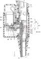
图3是沿着图2中的III-III线的内窥镜的局部剖视图。FIG. 3 is a partial cross-sectional view of the endoscope taken along line III-III in FIG. 2 .
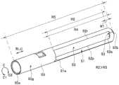
图4是图3的转动传递部件的放大立体图。FIG. 4 is an enlarged perspective view of the rotation transmission member of FIG. 3 .
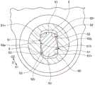
图5是以沿图3中的V-V线的输出部件及转动传递部件为主要部分的局部剖视图。FIG. 5 is a partial cross-sectional view of an output member and a rotation transmission member taken along line V-V in FIG. 3 as a main part.
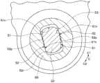
图6是示出图5的输出部件向一个方向旋转,贯通孔的内侧平面与转动传递部件的一部分接触的状态的局部剖视图。6 is a partial cross-sectional view showing a state in which the output member of FIG. 5 is rotated in one direction and the inner plane of the through hole is in contact with a part of the rotation transmission member.
图7是将在转动传递部件的外周面还设置有第4平面的变形例与贯通孔一起示出的局部剖视图。7 is a partial cross-sectional view showing a modification in which a fourth flat surface is further provided on the outer peripheral surface of the rotation transmission member, together with a through hole.
图8是将形成于图7的转动部件的外周面的第2平面及第4平面分别由1个构成的变形例与贯通孔一起示出的局部剖视图。8 is a partial cross-sectional view showing a modification in which each of the second plane and the fourth plane formed on the outer peripheral surface of the rotating member of FIG. 7 is composed of one through hole.
图9是将在转动传递部件的外周面形成有D切口部的变形例与贯通孔一起示出的局部剖视图。9 is a partial cross-sectional view showing a modification in which a D-notch portion is formed on the outer peripheral surface of the rotation transmission member, together with a through hole.
具体实施方式Detailed ways
下面,参照附图对本发明的实施方式进行说明。另外,在以下说明所使用的各图中,设各结构要素为附图上能够识别的程度的大小,所以,比例尺按照每个结构要素而不同。即,本发明并限于这些图中记载的结构要素的数量,结构要素的形状,结构要素的大小的比率,以及各结构要素的相对位置关系。Hereinafter, embodiments of the present invention will be described with reference to the accompanying drawings. In addition, in each drawing used for the following description, since each component is set to the size of the degree which can be recognized on the drawing, the scale is different for each component. That is, the present invention is not limited to the number of the constituent elements, the shape of the constituent elements, the ratio of the size of the constituent elements, and the relative positional relationship of the constituent elements described in these figures.
图1是示出具备具有本实施方式的驱动力传递机构的内窥镜的内窥镜系统的结构的概略的图,图2是在图1的内窥镜中由图1中的II线包围的部位的放大立体图,图3是沿着图2中的III-III线的内窥镜的局部剖视图。FIG. 1 is a diagram showing a schematic configuration of an endoscope system including an endoscope having a driving force transmission mechanism according to the present embodiment, and FIG. 2 is surrounded by line II in FIG. 1 in the endoscope of FIG. 1 . 3 is an enlarged perspective view of the part of FIG. 3 , and FIG. 3 is a partial cross-sectional view of the endoscope along the line III-III in FIG. 2 .
如图1所示,内窥镜系统200的主要部分构成为具有内窥镜1和与该内窥镜1连接的控制系统14。As shown in FIG. 1 , the main part of the
内窥镜1的主要部分构成为具有:插入部2,其形成为沿轴向J呈长条状延伸,并且插入到对象物内;操作部3,其与该插入部2的轴向J的作为另一侧的基端侧J2(以下简称为基端侧J2)连续地设置;通用软线4,其从该操作部3延伸,连接器5,其可相对于设置于该通用软线4的延伸端的控制系统14自由装卸。The main part of the endoscope 1 is configured to include an
另外,在插入部2、操作部3、通用软线4、连接器5内贯穿插入有由光导12、未图示的摄像单元、摄像缆线构成的观察光学系统13。In addition, an observation
进而,在操作部3、通用软线4、连接器5内贯穿插入有马达电源缆线11。Furthermore, a motor
插入部2构成为具有:前端部2a,其设置在轴向J的前端(以下简称为前端);弯曲部2b,其与该前端部2a的轴向J的基端(以下简称为基端)连续设置,并且向多个方向弯曲自如;以及挠性管部2c,其与该弯曲部2b的基端连续设置,具有挠性。The
操作部3的主要部分构成为具有把持部3a和防折件3b。The main part of the
在把持部3a上设置有在向多个方向弯曲操作弯曲部2b时由操作者操作的弯曲操作旋钮3c和内窥镜1的未图示的各种操作开关等。The
防折件3b与把持部3a的前端连接设置,并且与挠性管部2c的基端2c连接,防止挠性管部2c的弯折。The bending
控制系统14的主要部分构成为具有光源14a、处理器14b、监视器14c、控制器14d和输入开关14e。The main part of the
光源14a经由光导管12向对象物内供给照明光。The
另外,处理器14b进行图像处理,使得由观察光学系统13的未图示的摄像单元拍摄的对象物内的图像显示在监视器14c上。In addition, the
进而,控制器14d除了对内窥镜系统200整体进行驱动控制之外,还经由马达电源缆线11对与该马达电源缆线11电连接的后述的电动马达80进行驱动控制。Furthermore, the
另外,输入开关14e由键盘、脚踏开关等构成,由操作者向控制器14d输入电动马达80的驱动指示。The
在此,在插入部2和操作部3内设置有驱动力传递机构100。驱动力传递机构100的主要部分构成为具备作为驱动源的电动马达80、至少一个齿轮70、将该齿轮70及电动马达80保持在内部的壳体90、输出部件60、转动传递部件50、转矩轴40、作为被驱动部件的齿轮30、作为外部设备的螺旋状结构体20。Here, a driving
在本实施方式中,电动马达80设置在与操作部3的防折件3b连接的壳体90内。另外,壳体90也可以与挠性管部2c的基端侧部分连接。In the present embodiment, the
马达电源缆线11与电动马达80电连接。电动马达80通过从输入开关14e向控制器14d进行输入,使输出轴81及设置在该输出轴81上的齿轮82(均参照图3)在绕后述的转动轴的方向C上转动。The
另外,电动马达80在壳体90内设置成输出轴81和齿轮82指向作为轴向J的一侧的前端侧J1(以下简称为前端侧J1)。In addition, the
另外,如图3所示,齿轮70与齿轮82啮合。齿轮70介于齿轮82与输出部件60之间。In addition, as shown in FIG. 3 , the
另外,在图3中举例示出齿轮70由多个构成的情况,但也可以由一个构成。In addition, in FIG. 3, although the case where the
另外,齿轮70的转动轴H与输出轴81或输出部件60的转动轴的延伸方向R平行或大致平行地配置。In addition, the rotation axis H of the
另外,转动轴的延伸方向R也与输出轴81平行或大致平行地配置。另外,转动轴的延伸方向R与轴向J平行或大致平行。In addition, the extending direction R of the rotating shaft is also arranged in parallel or substantially parallel to the
输出部件60的形成于外周面的未图示的齿轮与齿轮70啮合。由此,输出部件60从电动马达80经由输出轴81、齿轮82、齿轮70传递转动力,从而被电动马达80在绕转动轴的延伸方向R的方向C上进行转动驱动。A not-shown gear formed on the outer peripheral surface of the
另外,如图2、图3所示,输出部件60沿着转动轴的延伸方向R以R3的长度形成,并且沿着转动轴的延伸方向R从前端60a到基端60b在内部形成有具有R3的长度的贯通孔61。In addition, as shown in FIGS. 2 and 3 , the
转动传递部件50沿轴向J具有比贯通孔61长的R5的长度(R5>R3)。The
另外,转动传递部件50沿转动轴的延伸方向R从前端侧J1可滑动地贯穿插入于贯通孔61,由此,通过输出部件60的转动,从输出部件60传递绕转动轴的方向C的与输出部件60相同的转动方向的转动驱动力。In addition, the
如图1、图3所示,转矩轴40与转动传递部件50同轴状地连结在作为转动传递部件50的一端的前端50a上,并与转动传递部件50在绕转动轴的方向C上向相同方向转动。As shown in FIGS. 1 and 3 , the
另外,虽然未图示,但是转矩轴40由多层构成,为了将输出部件60的转动不仅沿一个方向C1还沿向另一个方向C2向齿轮30传递,转矩轴40具有各柔性的右旋线圈和左旋线圈交替层叠的公知的结构。In addition, although not shown, the
另外,转矩轴40以向插入部2的前端方向稍微压入而挠曲的状态组装。通过转矩轴40的挠曲,即使在插入部2极端弯曲的情况下或插入部2整体形成为环状的情况下,也能够防止转矩轴40的基端部被向插入部2侧拉入,始终维持转动传递部件50与输出部件60的连结。In addition, the
齿轮30连接到转矩轴40的末端40a,并且在绕转动轴的方向C上向与转矩轴40相同的方向转动。即,转矩轴40驱动齿轮30。另外,齿轮30在轴向J上的位置被固定。The
螺旋状结构体20例如设置在挠性管部2c的前端外周,通过齿轮30在绕转动轴的方向C上向与齿轮30相同的方向转动。另外,设置有螺旋状结构体20的挠性管部2c的位置不限于图1所示的位置。进而,螺旋状结构体20也可以设置在前端部2a的外周。The
另外,如图1所示,螺旋状构造体20在外周面沿着轴向J具有螺旋状的突起21。Moreover, as shown in FIG. 1, the
螺旋状结构体20中,突起21一边转动一边与作为对象物的体腔的内壁接触,由此使插入部2产生推进力,将位于从前端部2a离开的位置的体腔内的被检部位拉到前端部2a的接近位置。由此,提高观察光学系统13的观察性和内窥镜1的处置性。In the
另外,转矩轴40具有全长在轴向J上以如下方式变化的特性:为了拉近被检部位,例如在使螺旋状构造体20向一个方向C1旋转的情况下,全长在轴向J上与转动传递部件50一起收缩,在使螺旋状构造体20向另一个方向C2旋转的情况下,全长在轴向J上与转动传递部件50一起伸长。In addition, the
接着,用图4~图6示出输出部件60的贯通孔61及转动传递部件50的详细结构。Next, the detailed structures of the through-
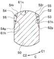
图4是图3的转动传递部件的放大立体图,图5是沿图3中的V-V线的以输出部件及转动传递部件为主要部分的局部剖视图,图6是示出图5的输出部件向一个方向旋转且贯通孔的内侧平面与转动传递部件的一部分接触的状态的局部剖视图。4 is an enlarged perspective view of the rotation transmission member of FIG. 3 , FIG. 5 is a partial cross-sectional view taken along the line V-V in FIG. 3 with the output member and the rotation transmission member as main parts, and FIG. 6 is a view showing the output member of FIG. A partial cross-sectional view of a state in which the direction is rotated and the inner plane of the through hole is in contact with a part of the rotation transmission member.
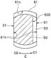
如图5、图6所示,形成于输出部件60的贯通孔61具有一对内侧平面61h,该一对内侧平面61h在内表面61n上相对于转动轴的延伸方向R平行地延伸且形成为直线状。As shown in FIGS. 5 and 6 , the through
即,贯通孔61的截面形状形成为具有一对对置的直线状的内侧平面61h的大致椭圆形状。That is, the cross-sectional shape of the through-
另外,如图4~图6所示,转动传递部件50在外周面50g上以如下方式形成有对置的一对第1平面51,一对第1平面51分别与转动轴的延伸方向R平行地从转动传递部件50的轴向J的一半部分延伸到基端50b,具有R4的长度。In addition, as shown in FIGS. 4 to 6 , on the outer
第1平面51在转动传递部件50贯穿插入于贯通孔61时,一部分与内侧平面61h对置,在将转动传递部件50贯穿插入于贯通孔61时作为引导件发挥功能。The first
并且,第1平面51还具有如下功能:在输出部件60向另一方向C2旋转的情况下,通过与内侧平面61h接触,将向另一方向C2的旋转驱动力传递到转动传递部件50。The first
另外,在外周面50g上,在轴向J上,以从比基端50b向前端侧J1靠近R1的位置向前端侧J1延伸设定间隔R2的方式,形成有对置的一对第2平面52。On the outer
另外,设定间隔R2形成为比贯通孔61的轴向J的长度R3稍长(R2>R3)。In addition, the set interval R2 is formed to be slightly longer than the length R3 of the through
第2平面52形成为相对于转动轴的延伸方向R平行且相对于第1平面51倾斜角度θ,以使沿轴向J的一端部52r位于比另一端部52p更靠转动传递部件50的转动轴的延伸方向R的中心侧。The second
并且,在转动传递部件50以第1平面51与内侧平面61h对置的方式贯穿插入于贯通孔61的状态下,第2平面52在输出部件60向一个方向C1旋转时,至少一部分,具体而言是一端部52r沿着轴向J与内侧平面61h接触,由此承受输出部件60的旋转力。In addition, when the
另外,当然也可以是内侧平面61h与第2平面52整体接触的结构。由此,转动传递部件50与输出部件60一起向一个方向C1旋转。In addition, it is needless to say that the inner
进而,在转动传递部件50中,以连接第2平面52的作为基端侧J2的端面的基端52b与第1平面51的方式,形成有一对第3平面53。另外,以连接第1平面51的前端侧的端面和转动传递部件50的外周面的方式设置有承受面51a。Furthermore, in the
如上所述,在将转矩轴40压入插入部而进行组装时,该转矩轴40的基端部要被从插入部压回,但通过使该承受面51a与输出部件60的插入部侧的端面抵接,能够维持转矩轴40被压入插入部的状态。As described above, when the
第3平面53在内侧平面61h与第2平面52的一端部52r接触时,如图3所示,与输出部件60的基端60b对置或抵接。When the inner
由此,当转动传递部件50向一个方向C1旋转时,如上所述,第3平面53防止转动传递部件50随着转矩轴40在轴向J上的收缩而从贯通孔61向前端侧J1脱落。即,第3平面53起到防止转动传递部件50从贯通孔61脱落的作用。Accordingly, when the
另外,在输出部件60向另一方向C2旋转的情况下,如上所述,转矩轴40沿轴向J伸长,但设置于转矩轴40的前端40a的齿轮30的轴向J的位置被固定。由此,转动传递部件50不会从贯通孔61向基端侧J2脱落,因此不需要所述那样的使用了第3平面53的防脱。In addition, when the
另外,驱动力传递机构100的其他结构与以往相同。In addition, the other structure of the driving
这样,在本实施方式中示出了贯穿插入于输出部件60的贯通孔61的转动传递部件50在外周面50g上形成有在将转动传递部件50贯穿插入于贯通孔61时作为引导件发挥作用的第1平面51。As described above, in the present embodiment, the
并且,示出了在转动传递部件50向一个方向C1旋转时,在外周面50g的至少一部分形成有贯通孔61的内侧平面61h所接触的第2平面52。In addition, when the
并且,示出了在外周面50g上形成有第3平面53,该第3平面53在转动传递部件50向一个方向C1旋转时,作为防止转动传递部件50随着转矩轴40在前端侧J1的收缩而从贯通孔61向前端侧J1脱落的防脱部件发挥作用。In addition, it is shown that a third
由此,仅通过将转动传递部件50以第1平面51为引导部以第1平面51与内侧平面61h对置的方式贯穿插入于贯通孔61,在输出部件60通过电动马达80的驱动而向一个方向C1旋转时,内侧平面61h与第2平面52的至少一部分接触。由此,能够使转动传递部件50、转矩轴40、齿轮30、螺旋状结构体20向一个方向C1旋转。In this way, only by inserting the
并且,在输出部件60与第2平面52的至少一部分接触的状态下,即使在与转动传递部件50一起向一个方向C1旋转的状态下,由于第3平面53与输出部件60的基端60b接触自如,因此能够防止转动传递部件50相对于贯通孔61向前端侧J1脱落。In addition, in the state where the
因此,由于第3平面53作为转动传递部件50的防脱部件发挥功能,因此无需像以往那样将转动传递部件50形成为在轴向J上较长,或者另行使用防脱部件。由此,能够防止内窥镜1的大型化,不仅不会降低组装时或修理时的作业性,而且能够削减制造,修理成本。Therefore, since the third
如上所述,能够提供一种内窥镜的驱动力传递机构100,该内窥镜的驱动力传递机构100具有如下结构:能够操作性良好地进行组装和修理,并且能够利用防止大型化的简单结构可靠地防止转动时转动传递部件50从输出部件60的贯通孔61脱落。As described above, it is possible to provide the endoscope driving
另外,以下使用图7、图8示出变形例。图7是将在转动传递部件的外周面还设置有第4平面的变形例与贯通孔一起示出的局部剖视图,图8是将形成于图7的转动部件的外周面的第2平面及第4平面分别由一个构成的变形例与贯通孔一起示出的局部剖视图。In addition, a modification is shown below using FIG. 7, FIG. 8. FIG. 7 is a partial cross-sectional view showing a modification in which a fourth plane is further provided on the outer peripheral surface of the rotation transmission member, together with through holes, and FIG. 8 is a second plane and a second plane to be formed on the outer peripheral surface of the rotation member in FIG. 7 . 4 is a partial cross-sectional view showing a modification example in which each of the planes is constituted by one, together with a through hole.
如上所述,在本实施方式中,在输出部件60、转动传递部件50、转矩轴40向另一方向C2旋转的情况下,转矩轴40向基端侧J2伸长,因此转动传递部件50不会从贯通孔61脱落。As described above, in the present embodiment, when the
但是,根据转矩轴40的结构,在向另一方向C2旋转的情况下,有时转矩轴40会向前端侧J1伸长,除此之外,有时在向一个方向C1旋转的情况下也会希望防止转动传递部件50从贯通孔61向基端侧J2脱落。However, depending on the structure of the
因此,在这些情况下,如图7所示,除了所述的一对第2平面52之外,只要在外周面50g上相对于第1平面51在与第2平面52相反的方向上形成一对第4平面54即可,该一对第4平面54以沿着轴向J的一端部54r比另一端部54p更位于转动传递部件50的转动轴的延伸方向R中心侧的方式倾斜。Therefore, in these cases, as shown in FIG. 7 , in addition to the pair of second
另外,如图8所示,第2平面52及第4平面54也可以分别仅由1个形成。In addition, as shown in FIG. 8 , each of the second
在该情况下,当输出部件60向另一方向C2旋转时,内侧平面61h与第4平面54的至少一部分接触将向另一方向C2的旋转力经由第4平面54传递给转动传递部件50。In this case, when the
并且,在防止转动传递部件50向基端侧J2脱落的情况下,在轴向J上与第3平面53对置并且形成为连接第1平面51和第4平面54的第5平面55作为防脱部件发挥功能。In addition, when the
另外,在通过转动传递部件50向一个方向C1的旋转,转矩轴40向前端侧J1伸长的情况下,与所述的本实施方式相同,第3平面53作为转动传递部件50的防脱部件发挥作用。In addition, when the
因此,在这种结构中,无论转动传递部件50的旋转方向如何,都能够得到与所述的本实施方式相同的效果。Therefore, in such a configuration, regardless of the rotation direction of the
另外,以下使用图9示出其他变形例。图9是将在转动传递部件的外周面形成有D切口部的变形例与贯通孔一起示出的局部剖视图。In addition, other modification examples are shown below using FIG. 9 . 9 is a partial cross-sectional view showing a modification in which a D-notch portion is formed on the outer peripheral surface of the rotation transmission member, together with a through hole.
如图9所示,在转动传递部件50的外周面50g上,除了第1平面51、第3平面53之外,也可以代替第2平面52、第4平面54而形成D切口部50D。As shown in FIG. 9 , in the outer
根据这种结构,无论在一个方向C1上还是在另一个方向C2上,内侧平面61h都与D切口部50D接触。According to this configuration, the inner
由此,通过第3平面53防止转动传递部件50从贯通孔61脱落,并且仅通过一个D切口部50D就能够将输出部件60向方向R1、R2的旋转可靠地传递给转动传递部件50,因此能够得到与所述的本实施方式或变形例相同的效果。Thereby, the
本申请以2018年5月16日在日本申请的特愿2018-094720号为优先权要求的基础进行申请,所述内容引用于本申请说明书,权利要求书,附图中。The present application is filed on the basis of the priority claim of Japanese Patent Application No. 2018-094720 filed in Japan on May 16, 2018, the contents of which are cited in the specification, claims, and drawings of the present application.
Claims (15)
Applications Claiming Priority (3)
| Application Number | Priority Date | Filing Date | Title |
|---|---|---|---|
| JP2018-094720 | 2018-05-16 | ||
| JP2018094720 | 2018-05-16 | ||
| PCT/JP2019/007102WO2019220735A1 (en) | 2018-05-16 | 2019-02-25 | Driving-force transmission mechanism of endoscope |
Publications (2)
| Publication Number | Publication Date |
|---|---|
| CN112074222Atrue CN112074222A (en) | 2020-12-11 |
| CN112074222B CN112074222B (en) | 2024-04-02 |
Family
ID=68540021
Family Applications (1)
| Application Number | Title | Priority Date | Filing Date |
|---|---|---|---|
| CN201980029051.8AActiveCN112074222B (en) | 2018-05-16 | 2019-02-25 | Driving force transmission mechanism of endoscope and endoscope |
Country Status (4)
| Country | Link |
|---|---|
| US (1) | US11931005B2 (en) |
| JP (1) | JP6796228B2 (en) |
| CN (1) | CN112074222B (en) |
| WO (1) | WO2019220735A1 (en) |
Citations (10)
| Publication number | Priority date | Publication date | Assignee | Title |
|---|---|---|---|---|
| JPH09300414A (en)* | 1996-05-17 | 1997-11-25 | Japan Steel Works Ltd:The | Screw connecting device of injection molding machine and assembling method thereof |
| JPH10159836A (en)* | 1996-11-29 | 1998-06-16 | Nec Corp | Bearing structure |
| JP2000210249A (en)* | 1999-01-22 | 2000-08-02 | Fuji Photo Optical Co Ltd | Endoscope with objective lens moving mechanism |
| JP2001208951A (en)* | 2000-01-24 | 2001-08-03 | Fuji Photo Optical Co Ltd | Endoscope with objective lens moving mechanism |
| CN103402416A (en)* | 2011-04-08 | 2013-11-20 | 奥林巴斯医疗株式会社 | endoscope |
| CN103826526A (en)* | 2012-03-21 | 2014-05-28 | 奥林巴斯医疗株式会社 | Endoscope and helical rotating part fitted on the insertion part of the endoscope |
| CN104349707A (en)* | 2012-08-31 | 2015-02-11 | 奥林巴斯医疗株式会社 | Insertion body, insertion device, rotation unit, and rotational force transmission unit |
| WO2015019675A1 (en)* | 2013-08-06 | 2015-02-12 | オリンパスメディカルシステムズ株式会社 | Insertion device |
| CN107072499A (en)* | 2015-07-15 | 2017-08-18 | 奥林巴斯株式会社 | The driving force transfer mechanism of Medical Devices |
| CN107530135A (en)* | 2015-04-17 | 2018-01-02 | 奥林巴斯株式会社 | Medical manipulator |
- 2019
- 2019-02-25CNCN201980029051.8Apatent/CN112074222B/enactiveActive
- 2019-02-25WOPCT/JP2019/007102patent/WO2019220735A1/ennot_activeCeased
- 2019-02-25JPJP2020518995Apatent/JP6796228B2/enactiveActive
- 2020
- 2020-11-10USUS17/093,906patent/US11931005B2/enactiveActive
Patent Citations (10)
| Publication number | Priority date | Publication date | Assignee | Title |
|---|---|---|---|---|
| JPH09300414A (en)* | 1996-05-17 | 1997-11-25 | Japan Steel Works Ltd:The | Screw connecting device of injection molding machine and assembling method thereof |
| JPH10159836A (en)* | 1996-11-29 | 1998-06-16 | Nec Corp | Bearing structure |
| JP2000210249A (en)* | 1999-01-22 | 2000-08-02 | Fuji Photo Optical Co Ltd | Endoscope with objective lens moving mechanism |
| JP2001208951A (en)* | 2000-01-24 | 2001-08-03 | Fuji Photo Optical Co Ltd | Endoscope with objective lens moving mechanism |
| CN103402416A (en)* | 2011-04-08 | 2013-11-20 | 奥林巴斯医疗株式会社 | endoscope |
| CN103826526A (en)* | 2012-03-21 | 2014-05-28 | 奥林巴斯医疗株式会社 | Endoscope and helical rotating part fitted on the insertion part of the endoscope |
| CN104349707A (en)* | 2012-08-31 | 2015-02-11 | 奥林巴斯医疗株式会社 | Insertion body, insertion device, rotation unit, and rotational force transmission unit |
| WO2015019675A1 (en)* | 2013-08-06 | 2015-02-12 | オリンパスメディカルシステムズ株式会社 | Insertion device |
| CN107530135A (en)* | 2015-04-17 | 2018-01-02 | 奥林巴斯株式会社 | Medical manipulator |
| CN107072499A (en)* | 2015-07-15 | 2017-08-18 | 奥林巴斯株式会社 | The driving force transfer mechanism of Medical Devices |
Also Published As
| Publication number | Publication date |
|---|---|
| US11931005B2 (en) | 2024-03-19 |
| JP6796228B2 (en) | 2020-12-02 |
| CN112074222B (en) | 2024-04-02 |
| US20210100430A1 (en) | 2021-04-08 |
| WO2019220735A1 (en) | 2019-11-21 |
| JPWO2019220735A1 (en) | 2021-01-07 |
Similar Documents
| Publication | Publication Date | Title |
|---|---|---|
| US9636001B2 (en) | Introduction device | |
| EP2229868A1 (en) | Endoscope | |
| JP5802856B2 (en) | Insertion device | |
| CN100496376C (en) | endoscope | |
| US10863887B2 (en) | Insertion device having universal cord with extending transmission member | |
| CN103917148A (en) | Endoscope system | |
| US20150148607A1 (en) | Driving force transmitting unit, insertion instrument, rotary unit, insertion body assembly, and insertion device | |
| US20160353975A1 (en) | Bending operation mechanism for endoscope | |
| EP2954832A1 (en) | Insertion device | |
| JP6072390B1 (en) | Drive force transmission mechanism for medical devices | |
| US20140066713A1 (en) | Insertion device, rotating tubular member, and driving unit | |
| US20110288371A1 (en) | Endoscope device | |
| CN109414152B (en) | Insert device | |
| CN112074222A (en) | Driving force transmission mechanism of endoscope | |
| JPH05309066A (en) | Endoscope device | |
| US10105038B2 (en) | Insertion apparatus | |
| US10299659B2 (en) | Insertion instrument and insertion device | |
| CN109310273B (en) | Insertion device | |
| CN105979849B (en) | Insert device | |
| US20180042456A1 (en) | Attachment unit | |
| JP2021191315A (en) | Insertion device | |
| US20170196434A1 (en) | Insertion instrument and insertion device | |
| JP2020000336A (en) | Insertion apparatus |
Legal Events
| Date | Code | Title | Description |
|---|---|---|---|
| PB01 | Publication | ||
| PB01 | Publication | ||
| SE01 | Entry into force of request for substantive examination | ||
| SE01 | Entry into force of request for substantive examination | ||
| GR01 | Patent grant | ||
| GR01 | Patent grant |