CN112072759A - Modular power pack - Google Patents
Modular power packDownload PDFInfo
- Publication number
- CN112072759A CN112072759ACN202011040412.XACN202011040412ACN112072759ACN 112072759 ACN112072759 ACN 112072759ACN 202011040412 ACN202011040412 ACN 202011040412ACN 112072759 ACN112072759 ACN 112072759A
- Authority
- CN
- China
- Prior art keywords
- module
- power supply
- box
- control module
- power
- Prior art date
- Legal status (The legal status is an assumption and is not a legal conclusion. Google has not performed a legal analysis and makes no representation as to the accuracy of the status listed.)
- Pending
Links
- 238000004891communicationMethods0.000claimsabstractdescription12
- 238000004804windingMethods0.000claimsdescription11
- 238000006243chemical reactionMethods0.000claimsdescription8
- 230000000007visual effectEffects0.000claimsdescription7
- 230000035515penetrationEffects0.000claimsdescription3
- 230000001960triggered effectEffects0.000claimsdescription2
- 230000006870functionEffects0.000abstractdescription33
- 238000010586diagramMethods0.000description7
- 238000000034methodMethods0.000description7
- 230000005611electricityEffects0.000description4
- 230000008569processEffects0.000description3
- 230000000712assemblyEffects0.000description2
- 238000000429assemblyMethods0.000description2
- 230000005540biological transmissionEffects0.000description2
- 238000001514detection methodMethods0.000description2
- 230000006698inductionEffects0.000description2
- 238000009434installationMethods0.000description2
- 238000012986modificationMethods0.000description2
- 230000004048modificationEffects0.000description2
- 238000012545processingMethods0.000description2
- 230000009467reductionEffects0.000description2
- 230000009471actionEffects0.000description1
- 230000003044adaptive effectEffects0.000description1
- 230000003321amplificationEffects0.000description1
- 230000009286beneficial effectEffects0.000description1
- 239000003990capacitorSubstances0.000description1
- 230000008094contradictory effectEffects0.000description1
- 230000007812deficiencyEffects0.000description1
- 238000011161developmentMethods0.000description1
- 238000012423maintenanceMethods0.000description1
- 238000003199nucleic acid amplification methodMethods0.000description1
- 230000003287optical effectEffects0.000description1
- 230000000717retained effectEffects0.000description1
- 230000005236sound signalEffects0.000description1
Images


Classifications
- H—ELECTRICITY
- H02—GENERATION; CONVERSION OR DISTRIBUTION OF ELECTRIC POWER
- H02J—CIRCUIT ARRANGEMENTS OR SYSTEMS FOR SUPPLYING OR DISTRIBUTING ELECTRIC POWER; SYSTEMS FOR STORING ELECTRIC ENERGY
- H02J7/00—Circuit arrangements for charging or depolarising batteries or for supplying loads from batteries
- H02J7/0042—Circuit arrangements for charging or depolarising batteries or for supplying loads from batteries characterised by the mechanical construction
- H—ELECTRICITY
- H02—GENERATION; CONVERSION OR DISTRIBUTION OF ELECTRIC POWER
- H02J—CIRCUIT ARRANGEMENTS OR SYSTEMS FOR SUPPLYING OR DISTRIBUTING ELECTRIC POWER; SYSTEMS FOR STORING ELECTRIC ENERGY
- H02J7/00—Circuit arrangements for charging or depolarising batteries or for supplying loads from batteries
- H02J7/0029—Circuit arrangements for charging or depolarising batteries or for supplying loads from batteries with safety or protection devices or circuits
- H02J7/00304—Overcurrent protection
- H—ELECTRICITY
- H02—GENERATION; CONVERSION OR DISTRIBUTION OF ELECTRIC POWER
- H02J—CIRCUIT ARRANGEMENTS OR SYSTEMS FOR SUPPLYING OR DISTRIBUTING ELECTRIC POWER; SYSTEMS FOR STORING ELECTRIC ENERGY
- H02J7/00—Circuit arrangements for charging or depolarising batteries or for supplying loads from batteries
- H02J7/0029—Circuit arrangements for charging or depolarising batteries or for supplying loads from batteries with safety or protection devices or circuits
- H02J7/00308—Overvoltage protection
- H—ELECTRICITY
- H02—GENERATION; CONVERSION OR DISTRIBUTION OF ELECTRIC POWER
- H02J—CIRCUIT ARRANGEMENTS OR SYSTEMS FOR SUPPLYING OR DISTRIBUTING ELECTRIC POWER; SYSTEMS FOR STORING ELECTRIC ENERGY
- H02J7/00—Circuit arrangements for charging or depolarising batteries or for supplying loads from batteries
- H02J7/0029—Circuit arrangements for charging or depolarising batteries or for supplying loads from batteries with safety or protection devices or circuits
- H02J7/00309—Overheat or overtemperature protection
- H—ELECTRICITY
- H02—GENERATION; CONVERSION OR DISTRIBUTION OF ELECTRIC POWER
- H02J—CIRCUIT ARRANGEMENTS OR SYSTEMS FOR SUPPLYING OR DISTRIBUTING ELECTRIC POWER; SYSTEMS FOR STORING ELECTRIC ENERGY
- H02J7/00—Circuit arrangements for charging or depolarising batteries or for supplying loads from batteries
- H02J7/0047—Circuit arrangements for charging or depolarising batteries or for supplying loads from batteries with monitoring or indicating devices or circuits
Landscapes
- Engineering & Computer Science (AREA)
- Power Engineering (AREA)
- Charge And Discharge Circuits For Batteries Or The Like (AREA)
Abstract
Translated fromChinese
Description
Translated fromChinese技术领域technical field
本发明涉及电源盒的技术领域,更具体地,涉及一种模块式电源盒。The present invention relates to the technical field of power supply boxes, and more particularly, to a modular power supply box.
背景技术Background technique
随着数码产品的飞速发展以及数码产品功耗的大幅提高,电子产品充电的次数越来越频繁。然而,市面上的充电线和电源适配器兼容性有所欠缺,充电线也不能很好地被收纳。电子产品更新换代的速度很快,为了适应新的协议,往往需要整体更换充电线和电源适配器,操作复杂,且更换成本高昂。With the rapid development of digital products and the substantial increase in power consumption of digital products, electronic products are charged more and more frequently. However, the compatibility of charging cables and power adapters on the market is lacking, and the charging cables cannot be stored well. The replacement of electronic products is very fast. In order to adapt to the new protocol, it is often necessary to replace the charging cable and power adapter as a whole. The operation is complicated and the replacement cost is high.
中国专利CN205335937U公开了一种便携式电子产品自适应电源盒,包括盒体、盒盖和控制单元,盒体的侧面设有插孔,插孔的侧壁上设有弹性扣,盒体内设有控制电路板和电源模块,电源模块的外侧连接有接线端子,控制电路板另一侧连接有多个输出端口,控制电路板还设有用于检测充电模式的充电模式检测芯片。上述方案针对不同国家的电源插头可以通过插孔进行更换,增加了电源盒对于不同国家电源插头的适用性,然而,上述方案的电源盒仅起到电源的作用,功能单一,无法满足智能家居及家居物联网的要求。Chinese patent CN205335937U discloses an adaptive power supply box for portable electronic products, which includes a box body, a box cover and a control unit. The side of the box body is provided with a socket, the side wall of the socket is provided with an elastic buckle, and the box is provided with a control unit. The circuit board and the power module are connected with terminals on the outside of the power module, and a plurality of output ports are connected on the other side of the control circuit board. The control circuit board is also provided with a charging mode detection chip for detecting the charging mode. The power plugs of the above solutions can be replaced by sockets for different countries, which increases the applicability of the power box to the power plugs of different countries. Requirements for Home IoT.
发明内容SUMMARY OF THE INVENTION
本发明的目的在于克服现有技术中的不足,提供一种模块式电源盒,电源适配器和充电线可更换,充电线自动收纳,整齐美观,且可满足变动的需求。The purpose of the present invention is to overcome the deficiencies in the prior art, and provide a modular power supply box, the power adapter and the charging cable can be replaced, the charging cable is automatically stored, neat and beautiful, and can meet the changing needs.
为解决上述技术问题,本发明采用的技术方案是:In order to solve the above-mentioned technical problems, the technical scheme adopted in the present invention is:
提供一种模块式电源盒,包括盒体及盖体,所述盒体与盖体可拆卸连接且所述盒体与所述盖体之间形成有腔体;所述盒体可拆卸连接有电源模块和若干功能模块,电源模块和若干功能模块均设于腔体内,若干功能模块与电源模块之间通信,多个电源模块之间可联动通信。A modular power supply box is provided, comprising a box body and a cover body, the box body and the cover body are detachably connected, and a cavity is formed between the box body and the cover body; the box body is detachably connected with a cavity. A power supply module and several functional modules, the power supply module and several functional modules are all arranged in the cavity, several functional modules communicate with the power supply module, and multiple power supply modules can communicate in linkage.
本发明的模块式电源盒,电源模块和功能模块均安装于腔体内,外表美观;由于电源模块和功能模块均可快速更换,可适应于不同种类设备的充电需要及可赋予电源盒以电源功能之外的各种功能,操作简便,更换成本低;各个功能模块可与电源模块通信,各个电源模块之间通信,可实现物联网的功能。In the modular power supply box of the present invention, the power supply module and the functional module are installed in the cavity, and the appearance is beautiful; since the power supply module and the functional module can be quickly replaced, it can be adapted to the charging needs of different types of equipment and can be given the power supply function to the power supply box. Various functions other than that are easy to operate and low cost to replace; each functional module can communicate with the power module, and the communication between each power module can realize the function of the Internet of Things.
进一步地,所述盖体的一端与盒体的一端卡接,盖体的另一端与盒体的另一端卡接。Further, one end of the cover body is clamped with one end of the box body, and the other end of the cover body is clamped with the other end of the box body.
进一步地,所述电源模块、功能模块均通过卡扣组件与盒体内壁连接。Further, the power module and the function module are connected to the inner wall of the box through a snap-fit assembly.
进一步地,所述卡扣组件包括设于电源模块、功能模块侧部的卡部以及设于盒体内壁的扣部,所述卡部与扣部均为弹性结构且所述卡部与扣部弹性卡接。Further, the clip assembly includes a clip part arranged on the side of the power module and the function module, and a clip part arranged on the inner wall of the box, the clip part and the clip part are both elastic structures, and the clip part and the clip part are both elastic structures. Elastic snap.
进一步地,所述功能模块包括受电模块,所述受电模块内盘绕有与电源模块电连接的充电线,所述盖体开设有容充电线穿过的穿出口。Further, the functional module includes a power receiving module, and a charging wire electrically connected to the power supply module is coiled in the power receiving module, and the cover body is provided with a penetration port through which the charging wire can pass.
进一步地,所述受电模块包括第一壳体、第二壳体、绕线盘及充电线,所述第一壳体与第二壳体中心处连接有转轴,所述绕线盘与转轴转动连接所述充电线盘绕于绕线盘外周,所述第一壳体和/或第二壳体设有容充电线穿出出线口。Further, the power receiving module includes a first casing, a second casing, a winding disk and a charging cable, a rotating shaft is connected to the center of the first casing and the second casing, and the winding disk is connected to the rotating shaft. The charging wire is rotatably connected and coiled around the outer circumference of the winding reel, and the first casing and/or the second casing are provided with an outlet for accommodating the charging wire.
进一步地,所述绕线盘包括设有弹簧槽的卷簧盒、与卷簧盒连接的盒盖及内置于弹簧槽内的卷簧,所述卷簧的一自由端与转轴连接,卷簧的另一自由端与卷簧盒连接;所述绕线盘连接有用于固定充电线伸出长度的制动组件。Further, the winding reel includes a coil spring case provided with a spring groove, a cover connected with the coil spring case, and a coil spring built in the spring groove, a free end of the coil spring is connected to the rotating shaft, and the coil spring is The other free end of the spool is connected with the coil spring box; the spool is connected with a braking assembly for fixing the protruding length of the charging cable.
进一步地,所述盒盖的一侧面设有若干圈第一凹槽,所述第二壳体内壁设有若干圈第二凹槽,所述第一凹槽和第二凹槽围绕成环形导电槽,所述第二壳体侧部设有与环形导电槽电连接的接触器件。Further, one side of the box cover is provided with several circles of first grooves, and the inner wall of the second shell is provided with several circles of second grooves, and the first grooves and the second grooves are surrounded in a ring-shaped conductive form. The side part of the second casing is provided with a contact device which is electrically connected with the annular conductive groove.
进一步地,所述电源模块包括AC-DC转换电路、电源管理模块及主控模块,所述AC-DC转换电路与电源管理模块信号连接,所述电源管理模块连接于主控模块,所述主控模块还与网络模块通信,通过网络模块可实时更新主控模块内置的通信协议及数据。Further, the power module includes an AC-DC conversion circuit, a power management module and a main control module, the AC-DC conversion circuit is signally connected to the power management module, the power management module is connected to the main control module, and the main control module is connected to the main control module. The control module also communicates with the network module, and the built-in communication protocol and data of the main control module can be updated in real time through the network module.
进一步地,所述功能模块包括连接于主控模块的可视化控制模块和保护模块,所述可视化控制模块包括显示模块、触摸控制模块、按键模块及光线感应模块,所述保护模块在输出电压电流超出设定电压电流值或温度超出设定温度值时触发保护功能;所述主控模块还连接有射频模块、红外模块、语音控制模块、二三插控制模块、温湿度传感模块、灯控调光模块、人体感应模块及物联网卡电话卡模块。Further, the functional module includes a visual control module and a protection module connected to the main control module, the visual control module includes a display module, a touch control module, a key module and a light sensing module, and the protection module is used when the output voltage and current exceed The protection function is triggered when the set voltage and current value or the temperature exceeds the set temperature value; the main control module is also connected with a radio frequency module, an infrared module, a voice control module, a two-three plug-in control module, a temperature and humidity sensing module, and a light control module. Optical module, human body induction module and Internet of things card phone card module.
与现有技术相比,本发明的有益效果是:Compared with the prior art, the beneficial effects of the present invention are:
本发明电源模块和功能模块均安装于腔体内,外表美观;由于电源模块和功能模块均可快速更换,可适应于不同种类设备的充电需要及可赋予电源盒以电源功能之外的各种功能,操作简便,更换成本低;The power supply module and the functional module of the present invention are both installed in the cavity and have a beautiful appearance; since the power supply module and the functional module can be quickly replaced, they can be adapted to the charging needs of different types of equipment and can be given to the power supply box with various functions other than the power supply function. , easy to operate and low replacement cost;
本发明的模块式电源盒内可自由安装各种功能模块,且各个电源盒内配置的电源模块之间可相互通信、相互联动,实现物联网的功能。Various functional modules can be freely installed in the modular power supply box of the present invention, and the power supply modules arranged in each power supply box can communicate with each other and be linked with each other to realize the function of the Internet of Things.
附图说明Description of drawings
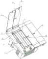
图1为本发明的模块式电源盒的结构示意图;1 is a schematic structural diagram of a modular power supply box of the present invention;
图2为受电模块的结构示意图;FIG. 2 is a schematic structural diagram of a power receiving module;
图3为受电模块的爆炸示意图;图4为本发明的模块式电源盒的电气原理图;FIG. 3 is an exploded schematic diagram of a power receiving module; FIG. 4 is an electrical schematic diagram of the modular power supply box of the present invention;
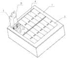
图5为模块式电源盒作为独立产品时的结构示意图;Figure 5 is a schematic structural diagram of the modular power supply box as an independent product;
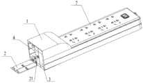
图6为模块式电源盒与插线板组合时的结构示意图;FIG. 6 is a schematic structural diagram when the modular power supply box is combined with the plug-in board;
附图中:1-盒体;2-盖体;21-穿出口;3-电源模块;31-AC-DC转换电路;32-电源管理模块;33-主控模块;4-功能模块;41-网络模块;43-可视化控制模块;431-显示模块;432-触摸控制模块;433-按键模块;434-光线感应模块;44-保护模块;45-通断换向模块;46-射频模块;47-红外模块;48-语音控制模块;49-二三插控制模块;410-温湿度传感模块;411-灯控调光模块;412-人体感应模块;413-物联网卡电话卡模块;5-卡扣组件;51-卡部;52-扣部;6-受电模块;61-第一壳体;62-第二壳体;621-弹针;63-绕线盘;631-卷簧盒;632-盒盖;64-转轴;65-出线口;66-排线收纳空间;67-排线出口;68-制动组件;681-第一凹道;682-第二凹道;683-第一卡顿位;684-第二卡顿位;685-滚珠;69-插槽;7-插线板。In the drawings: 1-box body; 2-cover body; 21-through outlet; 3-power module; 31-AC-DC conversion circuit; 32-power management module; 33-main control module; 4-function module; 41 -Network module; 43-Visual control module; 431-Display module; 432-Touch control module; 433-Button module; 434-Light sensor module; 44-Protection module; 47-infrared module; 48-voice control module; 49-two or three plug-in control module; 410-temperature and humidity sensor module; 411-light control dimming module; 412-human body sensor module; 413-Internet of things card phone card module; - Buckle assembly; 51- Buckle part; 52- Buckle part; 6- Power receiving module; 61- First shell; 62- Second shell; 621- Spring needle; Box; 632-box cover; 64-rotating shaft; 65-cable outlet; 66-cable storage space; 67-cable outlet; 68-brake assembly; 681-first groove; 682-second groove; 683 -The first stuck position; 684- the second stuck position; 685-ball; 69-slot; 7-plug board.
具体实施方式Detailed ways
下面结合具体实施方式对本发明作进一步的说明。其中,附图仅用于示例性说明,表示的仅是示意图,而非实物图,不能理解为对本专利的限制;为了更好地说明本发明的实施例,附图某些部件会有省略、放大或缩小,并不代表实际产品的尺寸;对本领域技术人员来说,附图中某些公知结构及其说明可能省略是可以理解的。The present invention will be further described below in conjunction with specific embodiments. Among them, the accompanying drawings are only used for exemplary description, and they are only schematic diagrams, not physical drawings, and should not be construed as restrictions on this patent; in order to better illustrate the embodiments of the present invention, some parts of the accompanying drawings will be omitted, The enlargement or reduction does not represent the size of the actual product; it is understandable to those skilled in the art that some well-known structures and their descriptions in the accompanying drawings may be omitted.
本发明实施例的附图中相同或相似的标号对应相同或相似的部件;在本发明的描述中,需要理解的是,若有术语“上”、“下”、“左”、“右”等指示的方位或位置关系为基于附图所示的方位或位置关系,仅是为了便于描述本发明和简化描述,而不是指示或暗示所指的装置或元件必须具有特定的方位、以特定的方位构造和操作,因此附图中描述位置关系的用语仅用于示例性说明,不能理解为对本专利的限制,对于本领域的普通技术人员而言,可以根据具体情况理解上述术语的具体含义。The same or similar numbers in the drawings of the embodiments of the present invention correspond to the same or similar components; in the description of the present invention, it should be understood that if there are terms “upper”, “lower”, “left” and “right” The orientation or positional relationship indicated by etc. is based on the orientation or positional relationship shown in the accompanying drawings, and is only for the convenience of describing the present invention and simplifying the description, rather than indicating or implying that the indicated device or element must have a specific orientation, with a specific orientation. Orientation structure and operation, so the terms describing the positional relationship in the accompanying drawings are only used for exemplary illustration, and should not be construed as a limitation on the present patent. Those of ordinary skill in the art can understand the specific meanings of the above terms according to specific situations.
实施例Example
如图1至图6所示为本发明的模块式电源盒的实施例,包括盒体1及盖体2,盒体1与盖体2可拆卸连接且盒体1与盖体2之间形成有腔体;盒体1可拆卸连接有电源模块3和若干功能模块4,电源模块3和若干功能模块4均设于腔体内,若干功能模块4与电源模块3之间通信,多个电源模块3之间可联动通信。Figures 1 to 6 show an embodiment of a modular power supply box of the present invention, comprising a
本实施例的模块式电源盒,在应用时可安装于开关底盒、插座或其他带电部件上,当安装于开关底盒时,可将盒体1和盖体2的外形结构设置为与开关底盒的外形匹配,以保证电源盒在开关底盒安装后的美观性。本实施例的电源模块3和盒体1之间可通过弹片或弹针连接以从开关底盒取电。本实施例中的电源盒安装于开关底盒时,可保留现有开关面板的功能,在腔体内还可根据使用需求安装功能模块4,如此,在不占用额外安装空间的前提下,丰富开关的功能,使其不仅可用作开关、还具有充电器、功能模块4联网灯及物联网联动的硬件设施等功能。The modular power supply box of this embodiment can be installed on the switch bottom box, socket or other live parts during application. When it is mounted on the switch bottom box, the external structure of the
在其中一个实施例中,盖体2的一端与盒体1的一端卡接,盖体2的另一端与盒体1的另一端卡接。在需要安装或更换腔体内功能模块4时,可打开盖体2,操作简便,合上盖体2后外表美观。当然,需要说明的是,本实施例中盒体1与盖体2的连接方式并不限于上述卡接的连接方式,其他能够实现合盖操作和开盖操作的可拆卸连接结构也可适用于本发明;盖体2可设置为一整块,也可设置多块,多块盖体2可分别与盒体1活动连接,当开启一块盖体2时,可装卸或维护电源模块3或一组功能模块4,从而尽可能避免对装卸维护工作对其他模块的影响。In one embodiment, one end of the
在其中一个实施例中,电源模块3、功能模块4均通过卡扣组件5与盒体1内壁连接,如图1所示。需要说明的是,本实施例中采用卡扣组件5是为了便捷连接操作而做出的优选,并不做为本发明的限制性规定,其他能够实现电源模块3、功能模块4与盒体1快速装卸的可拆卸连接结构也可适用于本发明。In one of the embodiments, the
在其中一个实施例中,卡扣组件5包括设于电源模块3、功能模块4侧部的卡部51以及设于盒体1内壁的扣部52,卡部51与扣部52均为弹性结构且卡部51与扣部52弹性卡接,如图1所示。卡部51和扣部52弹性卡接,卡部51和扣部52具有自锁和自动弹出的功能,操作简便、固定牢靠。另外,本实施例电源模块3、功能模块4侧部的卡部51可设置多组,多组卡部51均匀排布于电源模块3、功能模块4的侧壁,而盒体1内壁扣部52的位置固定,如此便可以通过不同卡部51与扣部52卡接调整电源模块3或功能模块4的高度。本实施例中也可在电源模块3、功能模块4侧部设置多组均匀布置的插槽69通过插槽与扣部52配合实现电源模块3或功能模块4的高度调整。In one embodiment, the
在其中一个实施例中,功能模块4包括受电模块6,受电模块6内盘绕有与电源模块3电连接的充电线,盖体2开设有容充电线穿过的穿出口21,如图2所示。其中,充电线的输入端与电源模块3电连接从电源模块3取电,充电线的中部盘绕设置,利于整齐收纳,充电线的输出端从穿出口21穿过。当设置多组盖体2时,穿出口21可设置于其中一组盖体2上,也可设置于相邻两组盖体2之间。需要说明的是,本实施例中充电线的功能不限于充电,还可用于数据传输。在其中一个实施例中,受电模块6包括第一壳体61、第二壳体62、绕线盘63及充电线,第一壳体61与第二壳体62中心处连接有转轴64,绕线盘63与转轴64转动连接;充电线盘绕于绕线盘63外周,第一壳体61和/或第二壳体62设有容充电线穿出出线口65,如图3所示。绕线盘63可绕转轴64旋转带动充电线的收放,便于充电线的整齐收纳,有效克服现有充电线布置凌乱的问题。另外,本实施例中充电线的充电接头可根据数码产品接口的不同设置为相应结构的接头,当然,充电接头也可采用与多种数码产品适配的组合接头;本实施例中出线口65可开设在第一壳体61、第二壳体62或同时开在第一壳体61、第二壳体62上。为了便于排线的布置,本实施例可在第一壳体61或第二壳体62内设置排线收纳空间66,并在排线收纳空间66旁侧设置排线出口67。In one of the embodiments, the
在其中一个实施例中,绕线盘63包括设有弹簧槽的卷簧盒631、与卷簧盒631连接的盒盖632及内置于弹簧槽内的卷簧,卷簧的一自由端与转轴64连接,卷簧的另一自由端与卷簧盒631连接,如图3所示。其中,卷簧可采用市售涡卷弹簧,涡卷弹簧位于内部的端头与转动轴固定连接,涡卷弹簧位于外侧的端头与弹簧槽的内壁连接,如此,在卷簧的作用下,不仅可稳定出线,而且利于充电线快速回位收纳。In one embodiment, the winding
在其中一个实施例中,绕线盘63连接有用于固定充电线伸出长度的制动组件68,以提高该电源盒的使用便利性。本实施例提供一组制动组件68,但需要说明的是,本发明的制动组件68不限于以下列举的结构,其他如制动按钮和顶紧弹簧的组合形式(制动按钮以及顶紧弹簧设置于外壳上的,顶紧弹簧顶压制动按钮,制动按钮顶压充电线,推动制动按钮,其可松开充电线)也可适用于本实用新型。在本实施例中,制动组件68包括滚珠685及设于卷簧盒631靠近第一壳体61一侧面的第一凹道681、第二凹道682、第一卡顿位683和第二卡顿位684,且第二凹道682设于第一凹道681内侧,第一卡顿位683位于第一凹道681头部和第二凹道682尾部的交接处,第一卡顿位683连通于第一凹道681和第二凹道682之间,第二卡顿位684位于第二凹道682头部和第二凹位尾部的交接处,第二卡顿位684连通于第一凹道681和第二凹道682之间。In one embodiment, the
本实施例实施时,充电线被拉出时,滚珠685沿着第一凹道681滚动,当拉出一定长度后,滚珠685进入第一卡顿位683,此时充电线长度被固定,可进行正常充电工作;若继续拉动充电线,第一凹道681的低位比第一卡顿位683的位置低,滚珠685进入第二凹道682内;继续拉充电线,滚珠685进入第二卡顿位684,此时充电线长度被固定,可进行正常充电工作;继续拉动充电线,滚珠685进入第二凹槽,拉动速度慢下来后,滚珠685滚入第一卡顿位683;当向回收充电线时,继续向外拉动一小段,滚珠685退回到第一凹道681内并放手,滚珠685在第一凹道681内循环,直至充电线收纳完成。In the implementation of this embodiment, when the charging cable is pulled out, the
在其中一个实施例中,盒盖632的一侧面设有若干圈第一凹槽,第二壳体62内壁设有若干圈第二凹槽,第一凹槽和第二凹槽围绕成环形导电槽,第二壳体62侧部设有与环形导电槽电连接的弹针621。环形导电槽内可布置排线,在第二壳体62上还可开设排线出口67便于排线布置。In one embodiment, one side of the
在其中一个实施例中,电源模块3包括AC-DC转换电路31、电源管理模块32及主控模块33,AC-DC转换电路31与电源管理模块32信号连接,电源管理模块32连接于主控模块33,主控模块33还与网络模块41通信,通过网络模块41可实时更新主控模块33内置的通信协议及数据,如图4所示。本实施例中,电源模块3与AC电源电连接,引入AC电压到AC-DC转换电路31,AC-DC电路通过整流、滤波降压后,输出基本电压到电源管理模块32,电源管理模块32启动后,给主控模块33供电,主控模块33和电源管理模块32通信,为功能模块4、网络模块41供电并进行通信。其中:网络模块41可为有线网络模块41、无线网络模块41或两种网络模块41的共存组合,网络模块41和主控模块33通信,主控模块33还与多个功能模块4进行通信,判断每个功能模块4所需要的供电电流电压;主控模块33通过识别各个功能模块4内的不同协议,对各个功能模块4进行不同的数据通信,调节电源管理模块32为各个功能模块4提供其所需的电压电流;相应地,各个功能模块4可向主控模块33发出连接局域网或互联网的请求;各个电源模块3可通过有线或无线的方式组成局域网,在未连接互联网的状态下也可以进行局域网之间的数据传输控制和联动功能,实现物联网的功能;电源模块3可通过无线网络或有线网络对各个功能模块4主控芯片的固件进行实时的数据更新升级。另外,本实施例还可赋予电源模块3以交流输出功能。In one embodiment, the
在其中一个实施例中,主控模块33还连接有可视化控制模块43,可视化控制模块43包括显示模块431、触摸控制模块432、按键模块433及光线感应模块434。其中:显示模块431用于显示各种由用户设置的数据,如网络信息、天气、时间、图像及各个功能模块4的可设置信息、各个电源模块3的状态信息、功能模块4的种类、各个功能模块4的状态信息、各个功能模块4采集的数据信息;触摸控制模块432和按键模块433用于对显示模块431显示出的各种信息进行控制操作;光线感应模块434通过对环境光强度的感应对显示模块431的亮度进行调节,避免和环境光线不匹配的情况;主控模块33和电源模块3通信时,处理电源模块3发出的各种数据,可传输给显示模块431进行显示。In one embodiment, the main control module 33 is further connected with a visual control module 43 , and the visual control module 43 includes a display module 431 , a touch control module 432 , a key module 433 and a light sensing module 434 . Wherein: the display module 431 is used to display various data set by the user, such as network information, weather, time, image and configurable information of each
在其中一个实施例中,主控模块33还连接有保护模块44,保护模块44在输出电压电流超出设定电压电流值或温度超出设定温度值时触发保护功能。主控模块33存储有各种充电协议,并且可通过充电模块反馈的电压电流,测算出需要充电设备的充电电压电流,传输给电源管理模块32,由电源管理模块32做出分析处理给出相应的电压电流;其中,充电模块反馈的电压电流可通过电压电流检测模块获得。本实施例的保护模块44可根据事先设置好的电压电流参数,对输出电压电流一旦超过设置的电压电流值,则触发保护功能;另外,本实施例的保护模块44还具有极限保护功能,当电压电流超过最大电压、最大电流时,自动启动保护功能。In one embodiment, the main control module 33 is further connected with a protection module 44, and the protection module 44 triggers a protection function when the output voltage and current exceeds the set voltage and current value or the temperature exceeds the set temperature value. The main control module 33 stores various charging protocols, and can calculate the charging voltage and current of the device that needs to be charged through the voltage and current fed back by the charging module, and transmit it to the
在其中一个实施例中,模块式电源盒还包括通断换向模块45,用以实现通断换向操作;通断换向模块45的操作可以通过触摸控制模块432和按键模块433实现,也可以通过移动端对电源模块3发送控制信号实现。In one embodiment, the modular power supply box further includes an on-off reversing module 45 to realize the on-off reversing operation; the operation of the on-off reversing module 45 can be realized by the touch control module 432 and the button module 433, or It can be realized by sending a control signal to the
在其中一个实施例中,模块式电源盒还包括射频模块46,射频模块46包括主控芯片、各个频段的控制芯片以及所匹配的天线,射频模块46和电源模块3通信,通信方式可采用蓝牙通信或Zigbee通信,不同通信方式可通过在射频模块46内置不同的通信协议实现。射频模块46和电源模块3进行通信,可通过电源模块3进行射频协议的更新,并能通过电源模块3将其学习到的射频信号对其他功能模块4进行分享,同时,电源模块3也能对射频模块46进行协议的更新和写入。In one embodiment, the modular power supply box further includes a radio frequency module 46. The radio frequency module 46 includes a main control chip, a control chip of each frequency band, and a matched antenna. The radio frequency module 46 communicates with the
在其中一个实施例中,模块式电源盒还包括红外模块47,红外模块47包括红外发射模块和红外接收模块,用于发射和接收学习红外遥控信号。红外接收模块接收遥控器发射的红外信号或接收电源模块3写入的红外信号,对红外信号进行解码后传输给主控模块33进行存储学习并通过电源模块3发送给其他功能模块4;红外发射模块用于发射信号,发射信号可通过在红外发射模块设置按钮实现、也可通过电源模块3发射控制信号给红外发射模块实现,而当采用后者方式时,电源模块3可进行联动操作,可利用PC、手机等移动端对红外发射做出联动控制。本实施例中,由于红外信号发射需要较高和较短的峰值电流,为了能够提供较大瞬时较大的电压电流,本实施例在红外发射模块和红外接收模块内置有大容量电容器。In one embodiment, the modular power supply box further includes an infrared module 47, and the infrared module 47 includes an infrared transmitting module and an infrared receiving module for transmitting and receiving learning infrared remote control signals. The infrared receiving module receives the infrared signal emitted by the remote control or receives the infrared signal written by the
在其中一个实施例中,模块式电源盒还包括语音控制模块48,语音控制模块48包括扬声器、麦克风、主控芯片及滤波放大电路,其中,麦克风接收环境的声音信号并进行放大处理和降噪处理,对环境声音进行降噪、对人声进行放大,主控芯片对处理后的声音与内存的声音特征或通过电源模块3与服务器网络中存储数据进行对比,当匹配一致时唤醒设备、进入命令接收阶段。In one embodiment, the modular power box further includes a voice control module 48, and the voice control module 48 includes a speaker, a microphone, a main control chip, and a filter amplifying circuit, wherein the microphone receives ambient sound signals and performs amplification processing and noise reduction. The main control chip compares the processed sound with the sound characteristics of the memory or the data stored in the server network through the
在其中一个实施例中,模块式电源盒还包括二三插控制模块49,用于进行电量统计、由电源模块3接收控制信号进行通断控制,或将二三插控制模块49主控芯片处理过的电流电压、通断状态信息传送给电源模块3并由电源模块3传输给其他功能模块4进行联动控制。In one embodiment, the modular power supply box further includes a two-three-plug control module 49 for performing electricity statistics, receiving control signals from the
在其中一个实施例中,模块式电源盒还包括温湿度传感模块410,温湿度传感模块410监测温度信息和湿度信息并进行处理后传输给电源模块3,再由电源模块3将数据传输给其他功能模块4。In one embodiment, the modular power supply box further includes a temperature and humidity sensing module 410. The temperature and humidity sensing module 410 monitors the temperature information and the humidity information, processes and transmits the data to the
在其中一个实施例中,模块式电源盒还包括灯控调光模块411,通过PMW电路的PMW频率大小实现。灯控调光模块411可通过在灯控调光模块411设置按键或触摸键实现,也可通过电源模块3进行控制。In one of the embodiments, the modular power box further includes a light control and dimming module 411, which is implemented by the PMW frequency of the PMW circuit. The light control and dimming module 411 can be realized by arranging buttons or touch keys on the light control and dimming module 411 , and can also be controlled by the
在其中一个实施例中,模块式电源盒还包括人体感应模块412,当检测到人体时向电源模块3传输信号,由电源模块3控制相应的功能模块4做出相应的响应。In one embodiment, the modular power supply box further includes a human body sensing module 412, which transmits a signal to the
在其中一个实施例中,模块式电源盒还包括物联网卡电话卡模块413,用于在没有宽带网络连接或宽带网络中断的情况下,对接入局域网的设备进行互联网通信。物联网卡电话卡模块413将数据传输给电源模块3,由电源模块3对数据进行分发。In one of the embodiments, the modular power box further includes an IoT card calling card module 413 for performing Internet communication with devices connected to the local area network in the absence of broadband network connection or interruption of the broadband network. The IoT card phone card module 413 transmits the data to the
上述实施例中的可视化控制模块43、保护模块44、射频模块46、红外模块47、语音控制模块48、二三插控制模块49、温湿度传感模块410、灯控调光模块411、人体感应模块412及物联网卡电话卡模块413均属于前述的功能模块4,在具体应用时,上述各个功能模块4的外形均制备为与电源模块3、受电模块6外形相似的结构,可根据使用需要自由组合及快速卡接安装于盒体1的腔体内。上述各个功能模块4均可与该电源盒的电源模块3通信,当存在多个电源盒时,多个电源盒配置的电源模块3之间可互联组成局域网,相互联动通信,实现物联网的功能。其中,多个电源盒所配置的功能模块4可相同也可不同,当然功能模块4的种类也不限于上述列举的种类,应用时可根据应用场景的需要进行适应性调整。In the above embodiment, the visual control module 43, the protection module 44, the radio frequency module 46, the infrared module 47, the voice control module 48, the two-three-plug control module 49, the temperature and humidity sensing module 410, the light control and dimming module 411, the human body sensor The module 412 and the Internet of Things card and telephone card module 413 belong to the aforementioned
在其中一个实施例中,上述实施例的模块式电源盒用于墙壁开关。本实施例实施时,将盒体1安装于开关底盒,将盒体1和盖体2的外形结构设置为与开关底盒的外形匹配,外观与墙壁开关相似,以保证电源盒在开关底盒安装后的美观性。其中,电源模块3和盒体1之间可通过弹片或弹针621连接以从开关底盒取电。In one of the embodiments, the modular power box of the above embodiment is used for a wall switch. In the implementation of this embodiment, the
在另外一个实施例中,上述实施例中的模块式电源盒作为一独立的可移动的产品,可以按需安装在相应的位置,如图5所示。相对以上实施例,本实施例可将电源模块3设置为可充电储电的无线电源模块3,电源模块3的取电不依赖于外部电源,可随意移动,其不仅具备上述实施例中模块式电源盒的各种功能,还可用作移动电源、移动充电宝、无线遥控器等用途;或将电源模块3连接一充电模块,利用充电模块从外部电源向电源模块3接入电源,使用者可按需将模块式电源盒安装至需要安装的位置。In another embodiment, as an independent movable product, the modular power supply box in the above embodiment can be installed at a corresponding position as required, as shown in FIG. 5 . Compared with the above embodiment, in this embodiment, the
在另外一个实施例中,上述实施例中的模块式电源盒,可集成到插线板7上,为了外表美观,可将模块式电源盒集成在插线板7头部,如图6所示。本实施例中,电源盒的电源模块3可通过插线板的电源线从外接电源取电,也可将充电模块和电源模块3组合得到无线电源模块3。In another embodiment, the modular power supply box in the above-mentioned embodiment can be integrated into the
当然,需要说明的是,上述几种模块式电源盒的应用场景并不作为本发明的限制性规定,按照应用需求、相应地改变电源盒的外形、将上述实施例中的模块式电源盒安装在不同物体上的方式均应落入本发明的保护范围。Of course, it should be noted that the application scenarios of the above-mentioned several modular power boxes are not limited provisions of the present invention. According to the application requirements, the shape of the power box is correspondingly changed, and the modular power box in the above embodiment is installed. The manners on different objects should fall within the protection scope of the present invention.
在上述具体实施方式的具体内容中,各技术特征可以进行任意不矛盾的组合,为使描述简洁,未对上述各个技术特征所有可能的组合都进行描述,然而,只要这些技术特征的组合不存在矛盾,都应当认为是本说明书记载的范围。In the specific content of the above-mentioned specific embodiment, the technical features can be combined in any non-contradictory combination. For the sake of brevity, all possible combinations of the above-mentioned technical features are not described. However, as long as the combination of these technical features does not exist Inconsistencies should be considered within the scope of this specification.
显然,本发明的上述实施例仅仅是为清楚地说明本发明所作的举例,而并非是对本发明的实施方式的限定。对于所属领域的普通技术人员来说,在上述说明的基础上还可以做出其它不同形式的变化或变动。这里无需也无法对所有的实施方式予以穷举。凡在本发明的精神和原则之内所作的任何修改、等同替换和改进等,均应包含在本发明权利要求的保护范围之内。Obviously, the above-mentioned embodiments of the present invention are only examples for clearly illustrating the present invention, and are not intended to limit the embodiments of the present invention. For those of ordinary skill in the art, changes or modifications in other different forms can also be made on the basis of the above description. There is no need and cannot be exhaustive of all implementations here. Any modifications, equivalent replacements and improvements made within the spirit and principle of the present invention shall be included within the protection scope of the claims of the present invention.
Claims (10)
Translated fromChinesePriority Applications (1)
| Application Number | Priority Date | Filing Date | Title |
|---|---|---|---|
| CN202011040412.XACN112072759A (en) | 2020-09-28 | 2020-09-28 | Modular power pack |
Applications Claiming Priority (1)
| Application Number | Priority Date | Filing Date | Title |
|---|---|---|---|
| CN202011040412.XACN112072759A (en) | 2020-09-28 | 2020-09-28 | Modular power pack |
Publications (1)
| Publication Number | Publication Date |
|---|---|
| CN112072759Atrue CN112072759A (en) | 2020-12-11 |
Family
ID=73684439
Family Applications (1)
| Application Number | Title | Priority Date | Filing Date |
|---|---|---|---|
| CN202011040412.XAPendingCN112072759A (en) | 2020-09-28 | 2020-09-28 | Modular power pack |
Country Status (1)
| Country | Link |
|---|---|
| CN (1) | CN112072759A (en) |
Cited By (1)
| Publication number | Priority date | Publication date | Assignee | Title |
|---|---|---|---|---|
| CN113966036A (en)* | 2021-08-13 | 2022-01-21 | 埃米尔智能技术(上海)有限公司 | Integral type down lamp with power storehouse |
Citations (6)
| Publication number | Priority date | Publication date | Assignee | Title |
|---|---|---|---|---|
| JP2003272716A (en)* | 2002-03-14 | 2003-09-26 | Sony Corp | Battery device and electronic equipment using this |
| CN1551398A (en)* | 2003-05-07 | 2004-12-01 | ������������ʽ���� | Battery and functional expending box |
| CA2531295A1 (en)* | 2004-12-22 | 2006-06-22 | Odyne Corporation | Battery management and equalization system for batteries using power line carrier communications |
| KR20160018038A (en)* | 2014-08-07 | 2016-02-17 | 한승관 | Charger |
| CN205335937U (en)* | 2016-02-01 | 2016-06-22 | 深圳市明昕技术有限公司 | Portable electronic products self -adaptation box that charges |
| CN212323798U (en)* | 2020-09-28 | 2021-01-08 | 荣高平 | Modular power pack |
- 2020
- 2020-09-28CNCN202011040412.XApatent/CN112072759A/enactivePending
Patent Citations (6)
| Publication number | Priority date | Publication date | Assignee | Title |
|---|---|---|---|---|
| JP2003272716A (en)* | 2002-03-14 | 2003-09-26 | Sony Corp | Battery device and electronic equipment using this |
| CN1551398A (en)* | 2003-05-07 | 2004-12-01 | ������������ʽ���� | Battery and functional expending box |
| CA2531295A1 (en)* | 2004-12-22 | 2006-06-22 | Odyne Corporation | Battery management and equalization system for batteries using power line carrier communications |
| KR20160018038A (en)* | 2014-08-07 | 2016-02-17 | 한승관 | Charger |
| CN205335937U (en)* | 2016-02-01 | 2016-06-22 | 深圳市明昕技术有限公司 | Portable electronic products self -adaptation box that charges |
| CN212323798U (en)* | 2020-09-28 | 2021-01-08 | 荣高平 | Modular power pack |
Cited By (2)
| Publication number | Priority date | Publication date | Assignee | Title |
|---|---|---|---|---|
| CN113966036A (en)* | 2021-08-13 | 2022-01-21 | 埃米尔智能技术(上海)有限公司 | Integral type down lamp with power storehouse |
| CN113966036B (en)* | 2021-08-13 | 2024-10-11 | 埃米尔智能技术(上海)有限公司 | Integrated down lamp with power supply bin |
Similar Documents
| Publication | Publication Date | Title |
|---|---|---|
| CN202565178U (en) | Power supply adapter device | |
| CN108696783A (en) | With the wired of the earphone for facilitating charging with it is wireless between the method and apparatus that easily switch | |
| US11777246B2 (en) | Electrical pop out device | |
| CN219246122U (en) | Intelligent door with POE power supply and intelligent access control system | |
| CN112072759A (en) | Modular power pack | |
| CN212323798U (en) | Modular power pack | |
| CN208172539U (en) | Intelligent control switch, mobile power source and wire rod based on speech recognition | |
| CN208079076U (en) | A kind of both-end Bluetooth adapter | |
| CN109546477A (en) | Intelligent socket for house system | |
| CN210629539U (en) | Signal adapter | |
| CN207969042U (en) | Scene coordinated signals Intelligent wall switch | |
| CN212542869U (en) | USB extensible intelligent voice socket | |
| CN110247244B (en) | Embedded Module Electric Box | |
| CN215221208U (en) | Data line and data line control system | |
| CN101521340B (en) | Dual Power Outlet Group Device with Remote Power Control | |
| CN205208463U (en) | A floor lamp and its support for floor electrical equipment | |
| CN115692052A (en) | Wall switch panel with network routing function | |
| CN211315967U (en) | Intelligence house LED lamp with speech control function | |
| CN107370911A (en) | A kind of directing duplex communication system and communication sub-unit with Tally indicator light | |
| CN219106675U (en) | Intelligent socket with voice function | |
| CN113840199A (en) | Earphone set | |
| CN214101871U (en) | A kind of LED control system and LED remote control | |
| CN220935306U (en) | Neck hanging earphone | |
| CN110086033A (en) | A kind of portable electronic product polylinker charging intelligent robot | |
| CN110602144A (en) | Signal adapter and control method of terminal device |
Legal Events
| Date | Code | Title | Description |
|---|---|---|---|
| PB01 | Publication | ||
| PB01 | Publication | ||
| SE01 | Entry into force of request for substantive examination | ||
| SE01 | Entry into force of request for substantive examination |